

Page 1

10” Wireless LCD Television
FLM-1000WL
20060828
Page 2
p
panying
Important Safety
Instructions
CAUTION: TO REDUCE THE RISK OF ELECTRIC SHOCK, DO NOT
REMOVE COVER (OR BACK). NO USE-SERVICEABLE P ARTS INSIDE.
REFER SERVICING TO QUALIFIED SERVICE PERSONNEL.
POWER SUPPLY:
Connect the supplied adapter to the side of the DVD player in the slot marked “Power
In”. Plug the two-prong end of the power cord to an AC100-240V outlet. If you have
difficulty inserting the plug, turn it over and reinsert it, if the unit will not be used for a long
time, disconnect the plug from the outlet.
NOTE:
Before plugging the power cord into an AC outlet, make sure that all the connections
have been made.
The lightning flash with arrowhead symbol, within an equilateral triangle, is
intended to alert the user to the presence of uninsulated “dangerous
voltage” within the product’s enclosure that may be of sufficient magnitude
to constitute a risk of electric to
The exclamation point within an equilateral triangle is intended to alert the
user to the presence of important operating and maintenance (servicing)
instructions in the literature accom
ersons.
the appliance.
- -
1
Page 3

CAUTION: These servicing instructions are for use by qualified service personnel only.
To reduce the risk of electric shock, do not perform any servicing other than that
contained in the operating instructions unless you are qualified to do so.
Refer to service manual for servicing instructions.
1) Read these instructions.
2) Keep these instructions.
3) Heed all warnings.
4) Follow all instructions.
5) Do not use near water.
6) Clean only with dry cloth.
7) Do not block any ventilation openings. Maintain well ventilated conditions around
the product, do not put product on bed, sofa or anything that blocks ventilation.
Install in accordance with the manufacturer’s instructions.
8) Do not install near any heat objects such as radiators, heat registers, stoves, or
other apparatus (including amplifiers) that produce heat.
9) Do not defeat the safety purpose of the polarized or grounding-type plug. A
polarized plug has two blades with one wider than the other. A grounding type plug
has two blades and a third grounding prong. The wide blade or the third prong is
provided for your safety. If the provided plug does not fit into your outlet, consult an
electrician for replacement of the obsolete outlet.
10) Protect the power cord from being walked on or pinched particularly at plugs,
convenience receptacles, and the point where they exit from the apparatus.
11) Only use attachments/accessories specified by the manufacturer.
12) Use only with the cart, stand, tripod, bracket, or table specified by the
manufacturer, or sold with the apparatus. When a cart is used, use
caution when moving the cart/apparatus combination to avoid injury
from tip-over.
13) Unplug this apparatus during lightning storms or when unused for long periods of
time.
14) Refer all servicing to qualified service personnel. Servicing is required when the
apparatus has been damaged in any way, such as power-supply cord or plug is
damaged, liquid has been spilled or objects have fallen into the apparatus, the
apparatus has been exposed to rain or moisture, does not operate normally, or has
been dropped.
15) Apparatus shall not be exposed to dripping or splashing and no objects filled with
liquids, such as vases, shall be placed on the apparatus.
- -
2
Important Safety
Instructions
Page 4

Note: Do not touch the color TFT LCD screen by hand directly.
Important Safety
Instructions
Notice
Based on the IEEE 802.11 st andard, that specifies the use of the 5GHz (802.11a) bands
of the radio spectrum having multi WiFi channel, the unit allows users to select the best
quality transmission mode to avoid interference and/or weaker signals.
- -
3
Page 5

This product is designed for easy portability and handling, with a stylish
appearance, with its wireless signal base station. It incorporates a wireless
TV/AV receiver.
Features
Multiple Mode
AV mode
WiFi A V mode.
In WiFi AV input status:
W-AV1 mode
W-AV2 mode
W-SV (S-VIDEO) mode
TV mode
High Quality Features
WiFi Channel Feature
Has a multi WiFi channels in order to avoid interruption.
Bitrate Feature
Adopt image compression bitrate to adjust image quality and transmission distance.
- -
4
Auto Searching and Connecting Function
The receiver of the unit can automatically search and connect the signal from of the base
unit.
High Resolution
Has an MPEG2 decoding format to achieve horizontal resolution more than 500 lines.
LCD (Liquid Crystal Display)
Designed with 10.2 inch color TFT LCD screen for superior image quality.
Stereo amplifier
Built-in 2x1.5w speakers output high quality sound.
NOTE: It is normal for a TFT screen to experience some light or dark spots appearing on
the LCD screen.
Page 6
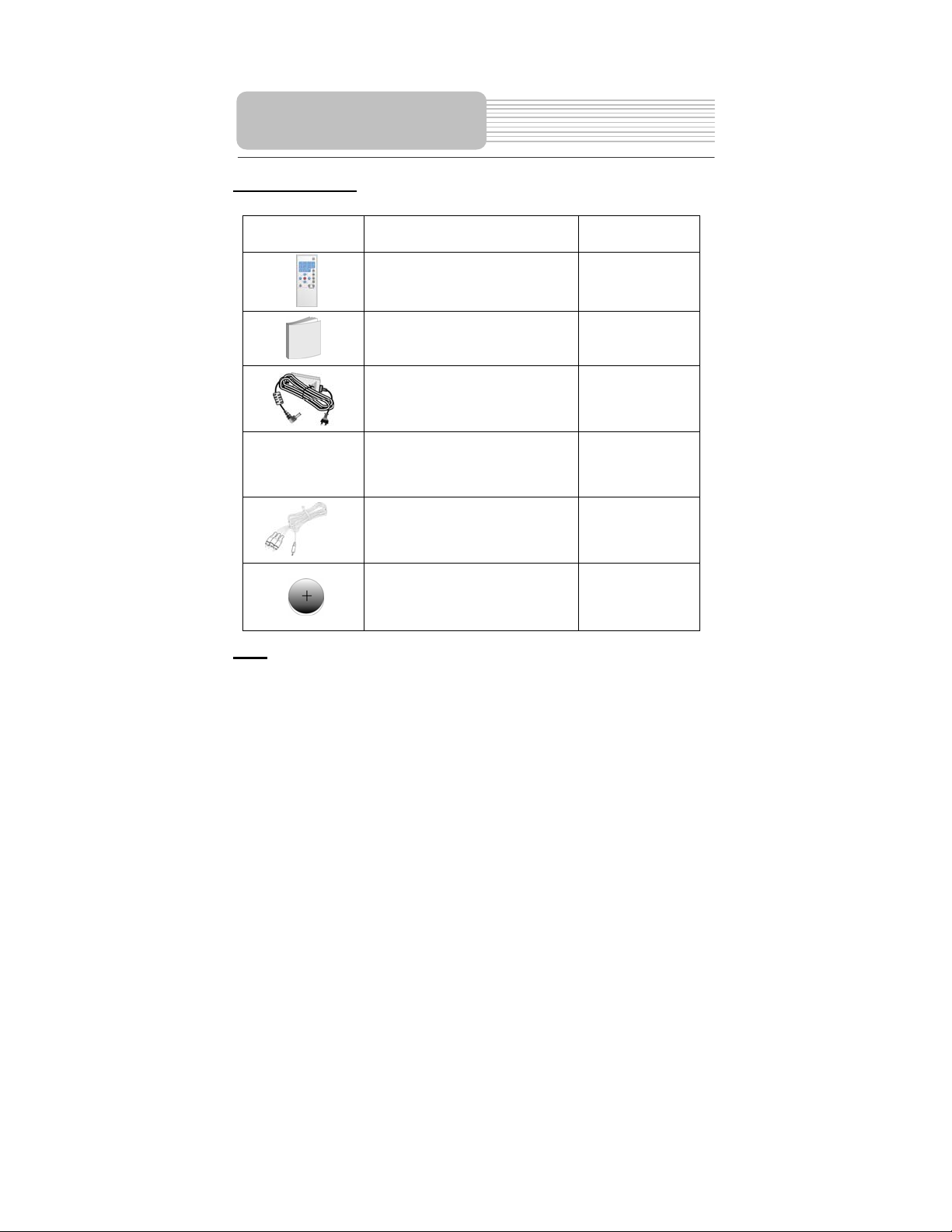
Accessories
Accessories List
ITEM
NAME
Remote Control Unit
QTY
1
NOTE
Accessories and their parts numbers are subject to modification without prior notice due
to improvements.
Owner’s Manual
Power Adapter
Audio/Video Cable
Audio/Video Cable
Battery for Remote Control
1
2
1
1
1
5
Page 7

Important Safety Instructions
Features
Accessories
View of the Receiver
View of the Signal
Signal System Connection
Receiver System Connection
Remote Control
Using the Wireless System
Troubleshooting
Specifications
Contents
…………………………………………….1
………………………………………….….4
………………………………………….….5
………………………………………..…...7
……………………………………………..9
…………………………………….…...…10
…………………………………………....12
…………………………………………....14
…………………………………………....16
…………………………………..………..23
…………………………………………….24
6
Page 8

View of the Receiver
Front View
1. WiFi/AV button
Switches between input and output status of the receiver of the unit.
2. MODE button
Adjust the brightness, contrast and color by pressing VOL/ VOLbutton on the
front panel to make the adjustment.
3. VOL/button
Adjusts the speaker volume, or to be used change the panel mode of the brightness,
contrast and/or color.
4. MENU button
Enter the wireless function menu.
5. INPUT/ ENT button
Shows the signal input selection among W-AV1, W-AV2, W-SV, or TV., or to confirm
the adjustment of wireless function menu selection.
6. CH/ button
Select TV channels or adjust a related wireless function combined with INPUT/ENT
button.
7
Page 9

View of the Receiver
7. Rechargeable battery pack
Charge the receiver’s battery pack via the DC IN Jack. .
8. Headphone Jack
Connect to the headphone.
9. AV IN/OUT Jack
Press the WIFI/AV button on the remote control or the receiver to switch between the
input or as the output status, of the jack.
10. DC IN Jack
Connect to AC power Adapter.
11. TFT LCD
10.2” color TFT LCD panel.
12. Speakers
13. Infrared receiver
Receives the signal from the remote control.
14. Charging Contacts
Charges the Rechargeable battery pack of this unit. NOT APPLICABLE FOR THIS
PRODUCT. SHOULD THIS SECTION BE REMOVED?
15. Battery charging indicator
Light turns red when the battery is in charging; Light turns green when the battery is
fully charged.
16. Power supply indicator
When the power switch button is pushed to on, the light turns saffron; then the light
turns green; when the unit is being used, the light turns red.
17. POWER Switch
Turn power on or off.
Note: Introduction of Wireless system working parts refers to Page 16—Page 19.
8
Page 10

View of the Signal
Front View
Back View
1. Power button
Press the button to turn power on or off.
2. Power supply light indicator
When power is on, the light is green.
3. Wireless light indicator
In the Operation status, the light is red.
4. Antenna
5. DC 9.5V IN
DC 9.5V adapter input jack.
6. S-Video input Jack
7. AV1/AV2
L/R audio and video input jack.
8. OUT
CATV signal output jack.
9. IN
CATV signal input jack.
9
Page 11

Antenna installation of the signal
Install the signal antennas as the following picture illustrates:
Signal System Connection
Pedestal installation of th e signal
Install the signal pedestal as the following picture illustrates using the two thumb screws:
10
Page 12

Signal System Connection
Connecting to Power Adapter /External AV Source/S-video Signal
source/ TV Signal source
NOTE: Do not connect the po wer cord until all other connections have been made.
Power is supplied through the provided appropriative power adapter, one end is
connected to the DC 9.5 V IN jack on the rear panel of the unit, the other end to th e
AC100~240V wall outlet.
Connect the signal to external signal source: W-AV1, W-AV2, W-SV, or TV.
Keep it away from a water source etc.
11
Page 13

Connecting to External AV Input
The unit supports AV signal function from nother equipment. Please use the audio/video
cable (included) to connect the unit to the external AV signal such as a DVD, VCR etc.
Press the WIFI/AV button on the remote control or the receiver to enter AV input status.
Receiver System
Connection
Connecting to TV
The unit supports AV signal output function to connect to another device. Connect as
shown below,
12
Page 14

Receiver System
Connection
Connecting to Headphones
Connect the headphones to the headphone jack on the unit.
When the headphones are connected, the speakers will automatically turn off. Please
adjust the volume before using headphones as this may cause hearing loss if they are too
loud.
Charging the battery by connecting to the Power Adapter
You need to use the appropriate power adapter to charge the battery in the TV receiver.
The power is supplied through the power adapter, one end is connected to the DC 9.5 V
IN jack on the rear panel of the unit, the other end to the AC100~240V wall outlet.
13
Page 15

Remote Control
Remote Control Drawing
1. [0-9]
Under TV mode, press to select TV channel.
2. [-/--/+100 ]
Under TV mode, press this button to show
channels above 100.
3. [CH+/ CH- ]
Press to select TV channels forward or
backward.
4. [VOL+/VOL- ]
Adjust the speaker volume, or change the
panel mode (brightness, contrast and color).
5. [ENT]
Press to confirm function selection.
6. [DISP]
In the TV mode, press to display the WiFi
channel number.
7. [MUTE]
Turn the speaker output on/of f .
8. [LAST]
Return to the TV channel last viewed.
9. [INPUT]
Displays the signal input: W-AV1, W-AV2,
W-SV, TV.
10. [WIFI/AV]
Switches between input and output status of
the receiver of the unit.
11. [M ODE]
Adjust the brightness, contrast and color using
the VOL/ VOL (buttons on the front panel.
12. [WIFI MENU]
Press to enter WiFi function setup.
14
Page 16

g
Remote Control
Preparation of Remote Control
Insert the batteries while observing the
+
-
1. Refer to the drawing; take out the
empty battery receptacle.
2. A separating film was applied to
the battery for shipment. Remove
this film.
3. Insert the battery into the
receptacle and insert it into the
remote.
4. Under normal usage the battery
will last for six months.
5. Take out battery when the remote
is not in use for a long time.
Using of Remote control
Point the remote control unit from no
more than about 5m from the remote
control sensor and within about 60
rees of the front of the unit.
de
The operating distance may vary
depending to the surrounding
brightness.
Notes:
Do not point bright lights directly at
the remote control sensor.
Do not place objects between the
remote control unit and the remote
control sensor.
Do not use this remote control unit
while simultaneously operating the
remote control unit of any other
equipment.
15
This drawing
is wrong!
Page 17

Connect a CATV or AV input signal to the base station of the unit. .
Connect the power adapter. The power supply indicator of the signal turns green.
Push power switch button of the receiver of the unit to on.
lights saffron, next, the light turns green, it then enters the working status, the light turns
red. When this happens, it will connect automatically.
Press ENT button to rescan the signal (Check whether the power switch button has
been pushed to “on” and the connection line has been connected correctly), the screen
will display:
Three screens should appear:
1. No signal is found:
Press ENT to rescan signal.
Connecting……
Signal not found
Press ENT to rescan
Searching For Signals X%
No Signal Found
Press ENT to Rescan
Using the Wireless
System
The power supply indicator
- 16 -
Page 18

Using the Wireless
System
2. Only one signal is found:
The system will be connected automatically.
3. Two or more signals are found:
Press CH+/CH- to select one of them and press the “ENT” key to confirm.
When there is no AV signal , for the input status of W-AV1, W-AV2 or W-SV, the screen
should display:
OR
OR
1 Signal Found
Search for signal
Connecting……
2 Signals Found
WiFi-WTV-XXX
WiFi-WTV-YYY
Search for signal
Press CH+/CH- to select
Press ENT to confirm
No input W-AV1
No input W-AV2
No input W-SV
- 17 -
Page 19

When the distance betw een sign al and th e re ceiver i s ov er the w ireless range , the sc reen w ill
display below:
When there is interference and signal reduction occurs,
Lost Signal
Weak Wireless Signal
Using the Wireless
System
the screen will display below:
- 18 -
Page 20

Using the Wireless
System
The base station of the unit possesses multi audio and video input jacks (TV, W-AV1,
W-A V2, W-SV), and it can be connected to an external signal.
can be accomplished by using the panel button on the unit or the remote control.
Changing the signal input
Switching Audio and Video Signal
• Panel button mode:
Press the “INPUT/ENT” button to switch among TV, W-AV1, W-AV2, W-SV.
• Remote control mode:
Press the "INPUT" button to switch among TV, W-AV1, W-AV2, W-SV.
Switching WiFi channel
You can switch the wireless channel easily. The wireless channels include the channel
numbers: 36, 40, 44, 153, 157, 161.
• Panel button mode:
In the AV or TV status, press the Menu button, The screen will display [WiFi
Channel XXX] , press the CH/ button to search a wireless channel forward
or backward. The screen will display [WiFi Channel YYY], press the
INPUT/ENT button to confirm. The screen will display [Channel Change to
YYY]. The Wireless channel has been changed.
• Remote control mode:
In the AV or TV status, press the WiFi MENU button. The screen will display
[WiFi Channel XXX], press the CH+, or CH- button to search a wireless channel
forward or backward. The screen will display [WiFi Channel YYY], press the
ENT button to confirm. The screen will display [Channel Change to YYY]. The
Wireless channel has been changed. (XXX-----current wireless channel,
YYY------changed to wireless channel).
Notes: When wireless channel is switched to [WiFi Channel AUTO], press the
INPUT/ENT button on the panel or ENT button on the remote control to scan the
wireless channels automatically. When an abnormal signal phenomenon appears, the
user can avoid the signal interruption by switching through the wireless channels.
- 19 -
Page 21

Using the Wireless
System
TV System Switching Operation
You can change the TV SYSTEM of the current TV channel.
• Panel button mode:
In the TV status, press the Menu button continuously, the screen will display
[Mono], press the CH/ button to select [Stereo] or [SAP], the TV System
switching is accomplished.
Remote control mode:
In the TV status, press the WIFI menu button, the screen will display [Mono], press
the CH+, or CH- button to select [Stereo] or [SAP], the TV System switching is
accomplished.
Channel Auto Scan Operation
During the first operation or when the TV has been moved to another area, you need to
perform the channel auto scanning. It will take several minutes to complete scanning.
After the scanning, the TV channels will be memorized and the first TV channel which
has TV signal will be displayed.
• Panel button mode:
In the TV status, press the Menu button continuously. The screen will display
[Channel Auto Scan NTSC STD], press the CH/ button to select one of the
following:[Channel Auto Scan NTSC IRC], [Channel Auto Scan NTSC HRC],
[Channel Auto Scan NTSC AIR], [Channel Scan Preset NTSC STD], [Channel
Scan Preset NTSC IRC], [Channel Scan Preset NTSC HRC] or [Channel Scan
Preset NTSC AIR]. Press the INPUT/ENT button to start the automatic tuner
scanning.
• Remote control mode:
In the TV status, press the WIFI menu button, The screen will display [Channel
Auto Scan NTSC STD], press the CH+, or CH- button to select one of the following:
[Channel Auto Scan NTSC IRC] , [Channel Auto Scan NTSC HRC], [Channel Auto
Scan NTSC AIR] , [Channel Scan Preset NTSC STD], [Channel Scan Preset
NTSC IRC], [Channel Scan Preset NTSC HRC] or [Channel Scan Preset NTSC
AIR]., Press the ENT button to start the automatic channel scanning.
The default is [Channel Auto Scan NTSC STD]. It is strongly suggested that user
select one of the following: [Channel Scan Preset NTSC STD], [Channel Scan Preset
NTSC IRC], [Channel Scan Preset NTSC HRC] or [Channel Scan Preset NTSC AIR].
During first operation or when the TV has been moved to another area, so as to enter
TV Type of the local location. Under the status, you don’t need to scan channel, the
channel range is within 2-125 under the status of [Channel Scan Preset NTSC STD],
[Channel Scan Preset NTSC IRC], [Channel Scan Preset NTSC HRC], channel range is
within 2-69 under the status of [Channel Scan Preset NTSC AIR].
- 20 -
Page 22

Using the Wireless
System
Channel FineTune Operation
You can adjust the current channel by using the TV FINETUNE feature to adjust the
TV’s image and audio quality to finally get the best viewing.
• Panel button mode:
In the TV status, press the Menu button continuously. The screen will display
[Fine Tune Channel], press the CH button continuously until the screen displays
[Fine Tune Channel >>>], press the CH button continuously. The screen will
display [Fine Tune Channel <<<].
• Remote control mode:
In the TV status, press the WIFI menu button. The screen will display [Fine Tune
Channel], press the CH+ continuously. The screen will display[Fine Tune
Channel >>>], press the CH- continuously, the screen will display [Fine Tune
Channel <<< ].
BITRATE Operation
Bitrate setup is helpful for image quality and transmission distance. High bitrate: image
is more clearly suitable for near distance viewing. Low bitrate: the wireless transmission
distance is further, suitable for far distance viewing. Please set the bitrate to low, if the
quality of image transmission is bad.
• Panel button mode:
In the TV status, press the Menu button continuously. Tthe screen will display
[MPEG Bitrate High], press the CH/ button, the screen will display [MPEG
Bitrate High], [MPEG Bitrate Mid], [MPEG Bitrate Low]. Press the INPUT/ENT
button to confirm.
• Remote control mode:
In TV status, press the WIFI menu button. The screen will display [MPEG Bitrate
High], press the CH+ or CH- button, the screen will display [MPEG Bitrate High],
[MPEG Bitrate Mid], [MPEG Bitrate Low]. Press ENT button to confirm.
Scan for signal
You can rescan the signal through the following operation:
• Panel button mode:
In the TV status, press the Menu button continuously, the screen will display [Scan
For Signals OFF], press the CH/ button to select [Scan For Signals ON], press
the INPUT/ENT button to start the signal scanning.
• Remote control mode:
In the TV status, press the WIFI menu button continuously, the screen will display
[Scan For Signals OFF] item, then press the CH+, or CH- button to select [Scan
For Signals ON] item, press the ENT button to start the signal scanning.
- 21 -
Page 23

The screen will display the hint column below:
Searching For Signals X%
Using the Wireless
System
The following operation refers to the page 16.
Notes: The operation will take some time.
Display Screen Setup
• Panel button mode:
In the AV or TV status, press the MODE button continuously to select brightness,
contrast, or hue, then press the VOLor VOL button to adjust the brightness,
contrast, or hue.
• Remote control mode:
In the AV or TV status, press the MODE button continuously to select brightness,
contrast, or hue, then press the VOL+ or VOL- button to adjust the brightness,
contrast, or hue.
Output/Input Switching Operation
• Panel button mode:
Press the WIFI/AV button on the panel to enter the AV input or AV output status.
• Remote control mode:
Press the WIFI/AV button on the remote control to enter the AV input or AV output
status.
- 22 -
Page 24

Troubleshooting
Symptom What To Check
LCD has does not display a
picture.
There is no image, or there
is a mosaic or unstable
image .
Speakers have no sound.
The remote control does not
work.
The receiver of the unit do es
not work in wireless mode.
The connection time in the
wireless status is beyond
one minute.
Signal inference occurs
Signal reduction occurs
• Make sure the power has been switched on and the
unit is connected correctly to the power adapter.
Check the signal input.
• Check the external audio and video signal input has
been connected, and the input is correct, and
receiving a signal within range.
• Check whether the volume is adjusted to the
minimum level, whether the headphone jack has
been connected to the headphone, whether the
receiver of the unit is in the pause status.
• Make sure there aren’t any obstruction s betw een the
remote control and the receiver of the unit.
• Make sure you are pointing the remote control at the
remote control sensor of the receiver of the unit.
• Make sure batteries are inserted correctly (check
polarity).
• Replace weak batteries.
• Make sure that the signal has been connected
correctly. .
• Make sure that the power switch of signal has been
pushed to on.
• Make sure that the distance between sign al and the
receiver is within 20 meters.
• Turn the power of thereceiver off.
• Make sure the signal is connected correctly.
• Push the power switch of the receiver to on.
Anyone of the following products may interference with
LF-61001 wireless transmission. Since there are more
products in the market that are using a wireless
technique. Check whether the instances below exist:
• Other wireless equipment, such as wireless Home
Router(2.4 GHz, 5GHz).
• Cordless Phone(2.4 GHz, 5.8GHz).
• Micro wave Ovens (2.4 GHz).
• Industrial or Medical Equipment (2.4 GHz, 5GHz
bands).
When the signal of the receiver is located below the a
floow or large object, these may cause a weaker
wireless signal. Check whether the instances below
exit:
• Large home appliance such as washer, dryer,
refrigerators etc.
• Wall/Door/Floor constructed with metal etc.
- 23 -
Page 25

TFT-LCD screen size 10.2 inches
TV Type NTSC
Wireless Standards IEEE802.11a
Wireless Channel Number 6
Communication Range
Modulation
Indoors: Approx 20m (Relying on environment )
OFDM
Specifications
UHF Low Frequency
UHF High Frequency
UHF Frequency
Power AC100240V50/60Hz
Signal Power Consumption 12W
Receiver Power Consumption 16W
Signal Dimensions 234mm x175mm x60mm
Receiver Dimensions 320mm x196mm x51mm
Receiver Weight approx 2.9kg
DESIGN AND SPECIFICATIONS ARE SUBJECT TO CHANGE WITHOUT NOTICE
55.25MHz151.25 MHz
157.25MHz451.25MHz
457.25MHz799.25MHz
"Polaroid" and “Polaroid and Pixel” are trademarks of Polaroid Corporation, Waltham, MA, USA.
For service, support and warranty information, visit www.polaroid.com.
- 24 -
 Loading...