

Page 1
CAMOPLAST MOUNTING KIT,
XP 850/550
P/N 2879457
Application
SPORTSMAN XP850/550 MY14 AND NEWER
Before you begin, read these instructions and check to be sure all parts and tools are accounted for. Please retain
these installation instructions for future reference and parts ordering information.
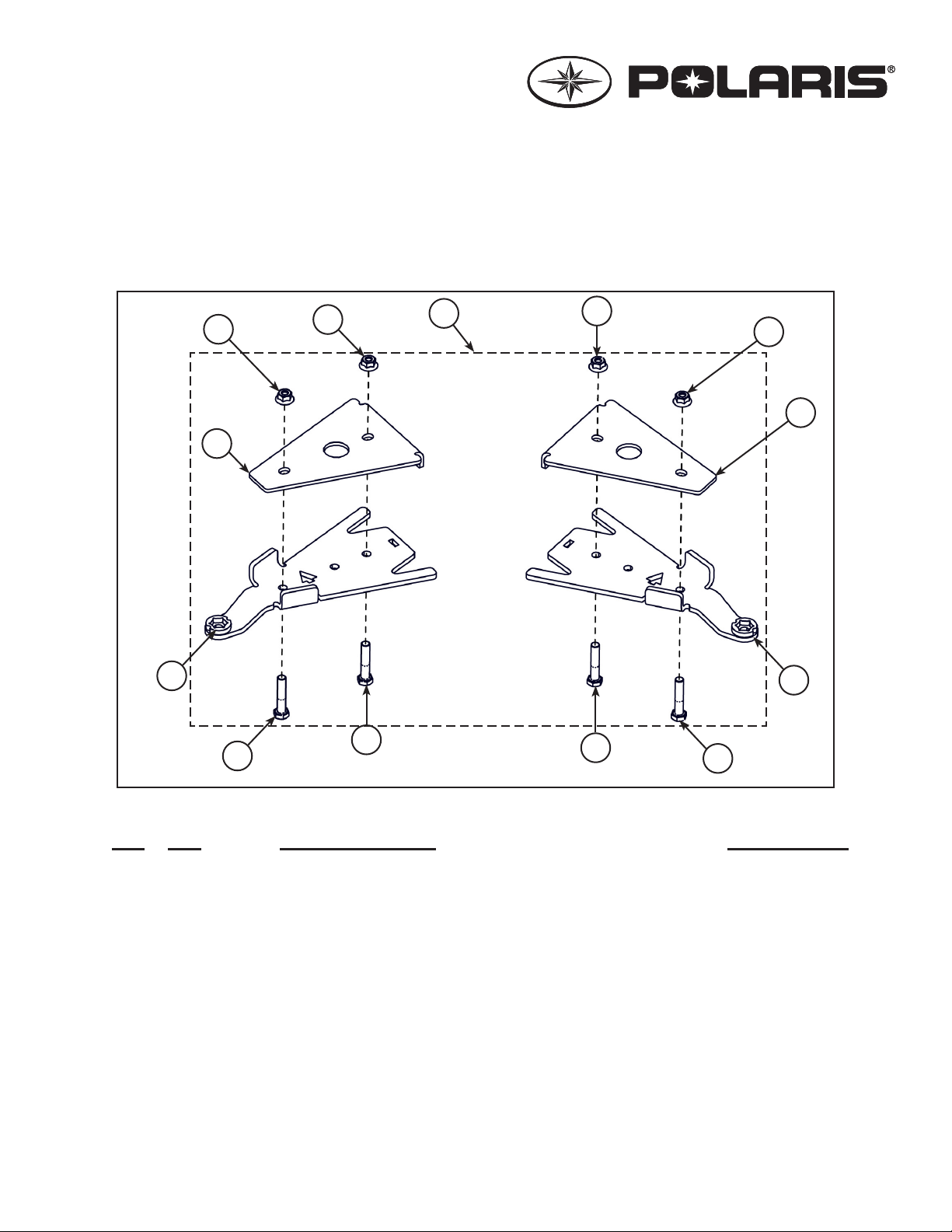
FRONT ANCHOR BRACKET:
2
Figure 1
6
4
5
6
5
1
6
6
4
3
5
5
Kit Contents:
Ref Qty Part Description Part Number
1 1 Front Bracket Kit 2205406
2 1 Front Left Anchor Bracket 3 1 Front Right Anchor Bracket 4 2 Front Bracket Cover 5 4 Hex Bolt-HCS, M10-1.5X55, 8.8, ZP, DIN931 6 4 Nylon Nut-FNN, M10-1.5, 8, ZP, DIN6926 -
-1-
Page 2
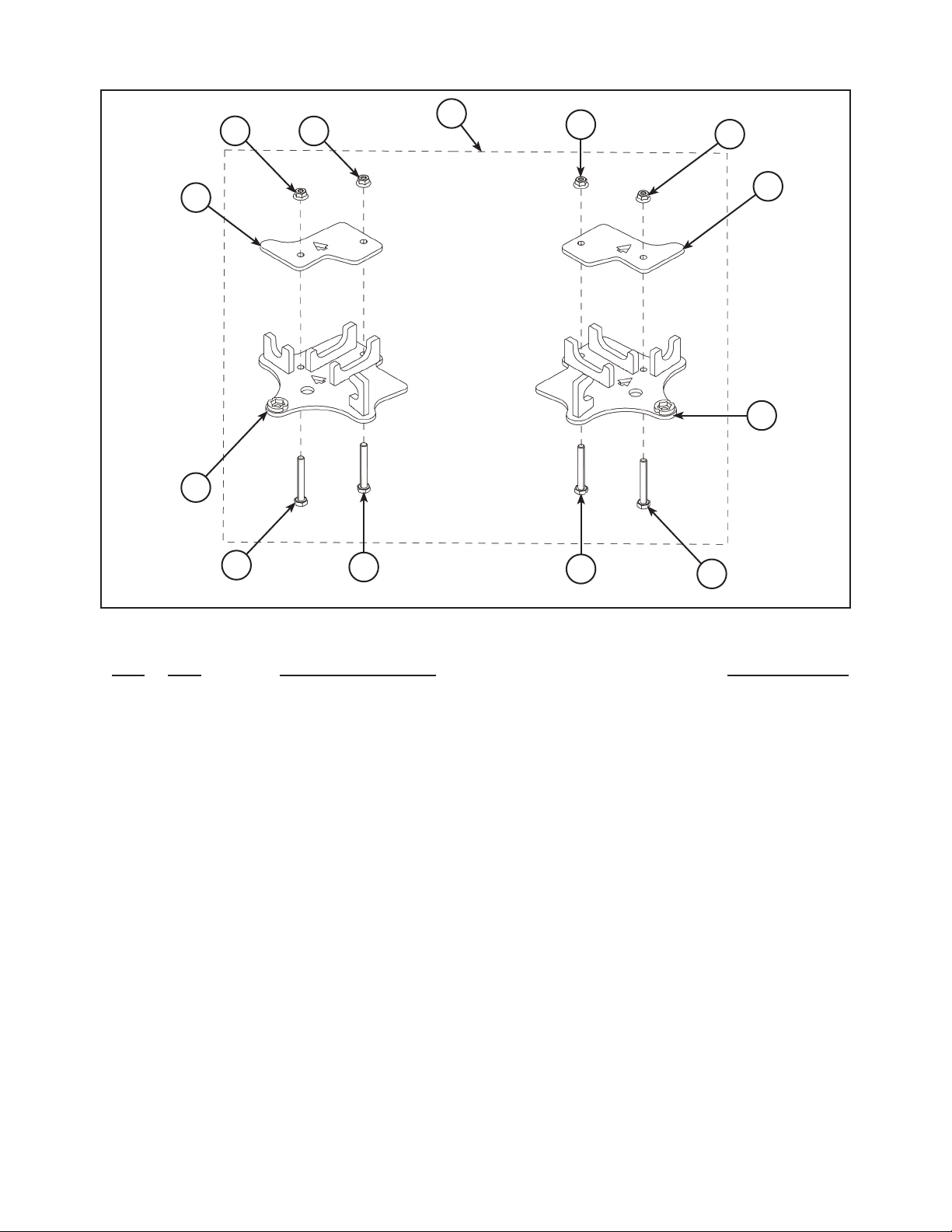
REAR ANCHOR BRACKET:
10
8
12
12
7
12
12
10
9
Figure 2
Kit Contents:
Ref Qty Part Description Part Number
7 1 Rear Bracket Kit 2205407
8 1 Rear Left Anchor Bracket 9 1 Rear Right Anchor Bracket 10 2 Rear Bracket Cover 11 4 Hex Bolt-HCS, M10-1.5X75, 8.8, ZP, DIN931 12 4 Washer-FNN, M10-1.5, 8, ZP, DIN6926 -
11
11
11
11
-2-
Page 3
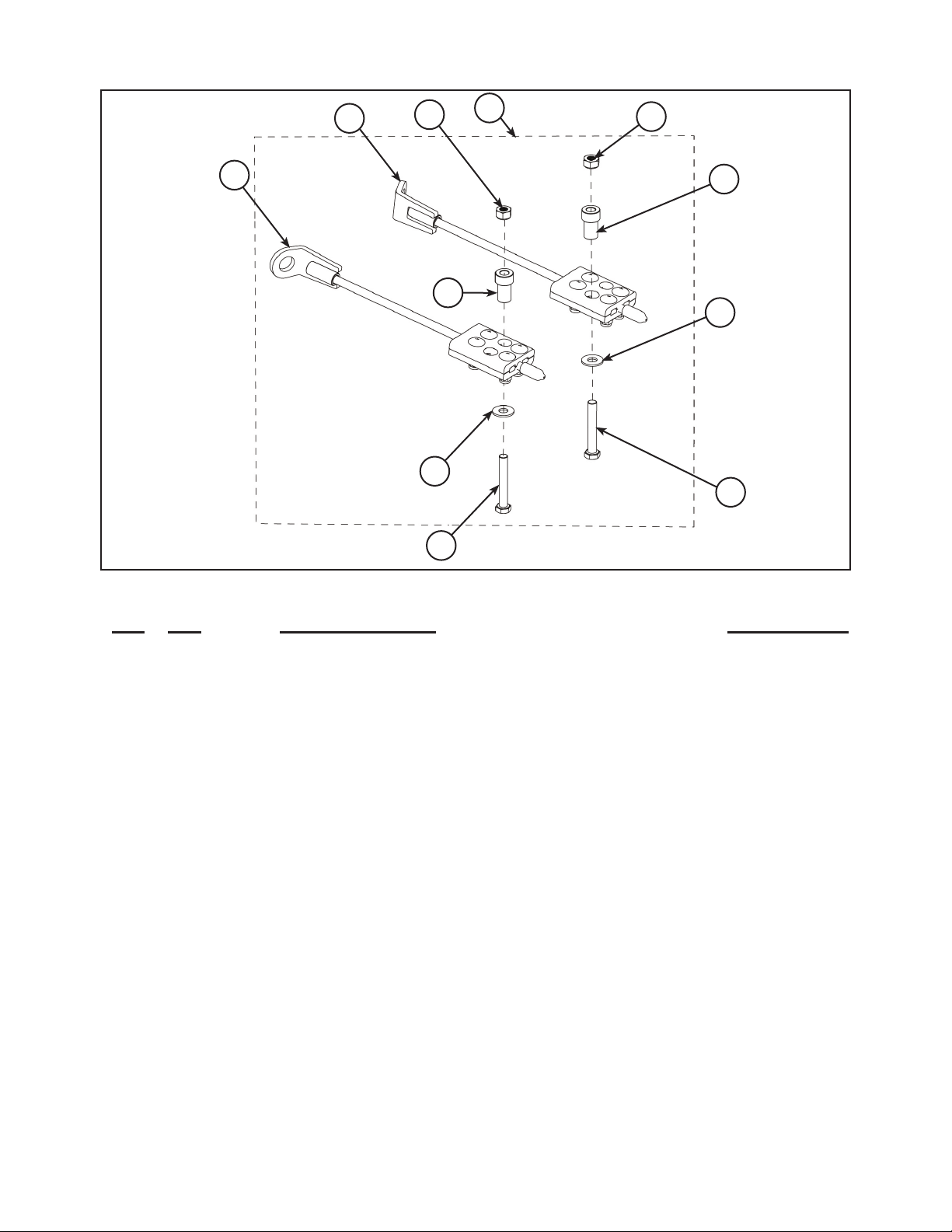
STEERING LIMITER ASSEMBLY:
Figure 3
14
14
18
17
16
15
13
18
16
17
15
Kit Contents:
Ref Qty Part Description Part Number
13 1 Steering Limiter Cable Assembly 2205456
14 2 Steering Limiter Cable 15 2 Hex Bolt-HCS, M10-1.5X60, 8.8, ZP, DIN931 16 2 Step Spacer 17 2 Washer-W, 7/16X1.0X0.072, 8, ZP, USS 18 2 Nylon Nut-NN, M10-1.5, ZP, 8, DIN982 -
-3-
Page 4
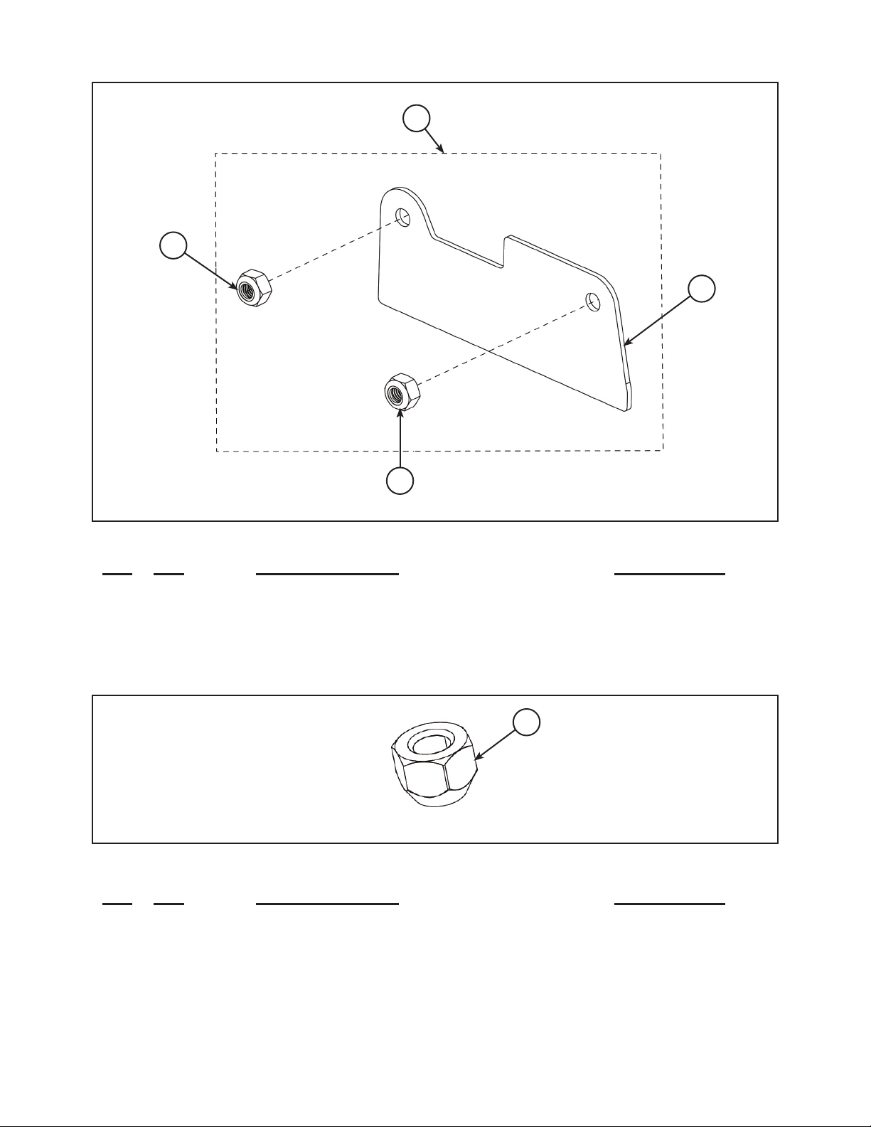
SUSPENSION STIFFENER:
21
19
20
Figure 4
Kit Contents:
Ref Qty Part Description Part Number
19 1 Stiffener Kit 2205471
20 1 Suspension Stiffener 21 2 Nylon Nut-NN, M10-1.5, 8, ZP, DIN982 -
WHEEL LUG NUT:
Figure 5
Kit Contents:
Ref Qty Part Description Part Number
22 16 Wheel Lug Nut-LN, M10-1.25X15, 8, ZP 2205455
1 Instructions 9924981
21
22
-4-
Page 5
Tools Required:
Lift Table or Floor Jack Torque Wrench 2 Jack Stands
Ratchet Metric Socket Set Metric Wrench Set
APPROXIMATE ASSEMBLY TIME: 60 minutes
IMPORTANT: Please read carefully each part of this document as well as the User Manual prior to
assembling, installing and using the track systems.
INSTALLATION INSTRUCTIONS:
CAUTION: Before beginning the installation, make sure you received all the components
included in the parts lists of the preceding pages.
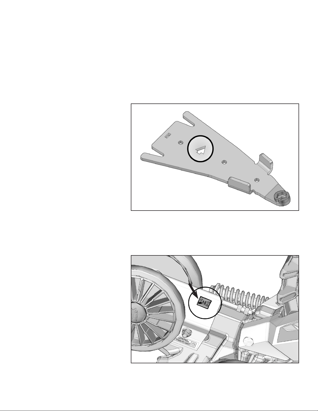
1. For installation purposes, directional
arrows have been cut out of the main
components in the anchor bracket
kits. These arrows indicate the front of
the vehicle relative to the component.
Figure 6.
Figure 6
PREPARATION:
WARNING: Never place body parts under the vehicle unless it is securely placed on
appropriate stands. Severe injuries could occur if the vehicle collapses or moves. Do not use
a lifting device as a secure stand.
1. Position the vehicle on a at and level
surface (or on a suitable lifting device),
shift the transmission to neutral and
turn off engine.
2. Identify and position each unit of
the track system near the position
indicated on the sticker. Figure 7.
Figure 7
-5-
Page 6

REAR TRACK SYSTEMS:
1. Using a lifting device, raise the rear of
the ATV and install appropriate stands.
Ensure that the vehicle is immobilized
and safe to work on.
2. Remove rear wheels. Make sure that
wheel studs and wheel hubs are free
of dirt. Figure 8.
3. If applicable, remove the CV joint
protectors from the A-arm.
4. Remove bolt, washers and spacer
bushings from the rear stabilizing rod
end. Figure 9.
Insert the bolt in the anchor bracket.
Figure 9a.
Figure 8
Bolt
NOTE: It is not possible to insert this
bolt once the bracket is attached to
the suspension arm.
Stabilizing Rod
Spacer Bushing
Washer
Figure 9
Anchor
Bracket
Figure 9a
Bolt
-6-
Page 7

5. Position anchor bracket under the
lower suspension arm; C-shaped
openings on bracket must t
suspension arm tubing. Figure 10 and
Figure 10a.
NOTE: Arrow cutout in anchor bracket
must face front of vehicle.
Anchor Bracket
Figure 10
Figure 10a
-7-
Page 8

6. Position the anchor bracket cover over
lower suspension arm. Insert
M10x75 mm bolts through bottom part
and use nuts provided to assemble
the two parts. Figure 11.
Torque the assembly to 37 ft. lbs.
(50 Nm). Figure 11a.
NOTE: Arrow cutout in anchor bracket
must face front of vehicle.
Nut
Nut
Anchor
Bracket
Cover
7. Secure the undercarriage to the rear
hub using the nuts provided in this
mount kit. Figure 12.
Figure 11
Figure 11a
Bolt
Bolt
NOTE: If needed, take rubber
protector off of hub.
NOTE: Ensure that the cotter pin of
the axle nut does not interfere with the
undercarriage hub.
NOTE: Torque lug nuts to 60 ft. lbs.
(81 Nm) at this time.
Nut
Figure 12
-8-
Page 9

8. Attach the stabilizing rod to the anchor
bracket, using the spacer bushings,
the at washer and nut. Torque to
52 ft. lbs. (70 Nm). Figure 13.
NOTE: Ensure that parts are
assembled in the correct order.
9. Inspect the rear track systems and
ensure that all mounting bolts were
correctly tightened during installation.
Lower the ATV to the ground and
install the front track systems on the
ATV.
Anchor
Bracket
Spacer
Bushing
Nut
REAR SUSPENSION STIFFENER:
1. Remove the ange nylon nuts from
the mounting bolts securing the rear
suspension lower arms near the front
of the differential. Figure 14.
Figure 13
Figure 14
Stabilizing Rod
Flat Washer
Figure 14a
-9-
Page 10

2. Insert the suspension stiffener plate
on the lower a–arms mounting bolts.
Secure the stiffener plate using the
nylon nuts provided. Torque the nuts
to 37 ft. lbs. (50 Nm). Figure 15 and
Figure 15a.
Suspension
Stiffener Plate
Nylon Nuts
Figure 15
FRONT TRACK SYSTEMS:
1. Using a lifting device, raise the front of
the ATV and install appropriate stands.
Ensure that the vehicle is immobilized
and safe to work on.
2. Remove front wheels. Make sure that
wheel studs and wheel hubs are free
of dirt. Figure 16.
Figure 15a
Figure 16
-10-
Page 11

3. If applicable, remove CV joint
protectors from the A-arms.
4. Remove the bolt, washer and
bushings from the front stabilizing rod
end. Figure 17.
Insert the bolt in the front anchor
bracket. Figure 17a.
NOTE: It is not possible to insert this
bolt once the bracket is attached to
the suspension arm.
Bolt
Stabilizing Rod
Spacer Bushing
Washer
Figure 17
Front Anchor
Bracket Ends
Figure 17a
-11-
Page 12

5. Position the bottom part of the
anchor bracket underneath the lower
suspension arm. Position the top part
over the suspension arm so the tab
slips in the slot in the bottom part.
Insert the M10x50 mm bolts through
the bottom and secure the two parts
together with the nuts provided.
Tighten assembly to 37 ft. lbs.
(50 Nm) of torque. Figure 18 and
Figure 18a.
Figure 18
Anchor Bracket
(Top Part)
Anchor Bracket
(Bottom Part)
Nut
6. Secure the undercarriage to the front
hub using the nuts provided in this
mount kit. Figure 19.
NOTE: If needed, take rubber
protector off of hub.
NOTE: Ensure that the cotter pin of
the axle nut does not interfere with the
undercarriage hub.
NOTE: Torque lug nuts to 60 ft. lbs.
(81 Nm) at this time.
Bolt
Figure 18a
Nut
Figure 19
-12-
Page 13

7. Insert step spacers in the steering
limiter assemblies. to get a left and
a right steering limiter assembly. For
correct identication Figure 20.
NOTE: The nuts should be placed
on the bottom side of the clamp
assembly.
8. On each FRONT track system,
position the bended extremity of
steering limiter on stabilizing rod
between hex grip and rubber damper
washer. Figure 21.
Front
Up
Left
Right
Spacers
Figure 20
Bended Extremity
9. Attach the stabilizing rod to the
anchor bracket, using the two spacer
bushings, at washer and nut. Torque
to 52 ft. lbs. (70 Nm). Figure 22.
NOTE: Ensure that parts are
assembled in the correct order.
Figure 21
Spacer
Bushing
Figure 22
Rubber Damper Washer
Stabilizing Rod
Anchor Bracket
Stabilizing Rod
Flat Washer
Nut
-13-
Page 14

10. Position aluminium blocks of steering
limiter assembly at center hole of
bottom part of front anchor bracket.
Use bolt, washer and nut to secure
the assembly in the center of the
anchor bracket. Tighten nut through
central opening of top part to
37 ft. lbs. (50 Nm). Figure 23.
Nut
NOTE: Bolt must be inserted through
the bottom of the assembly.
NOTE: Step spacer must be installed
in aluminium block hole that faces
front of vehicle.
Washer
Bolt
Figure 23
Use this hole to assemble
Front
Figure 23a
STEERING LIMITER ADJUSTMENT:
CAUTION: The track systems’ angle of attack must absolutely be set before beginning
steering limiter adjustment. Refer to the User Manual for angle of attack settings.
11. Make sure the cable can slide in the
clamping blocks. Turn the vehicle’s
steering to its maximum point of
travel on the left hand side. Maintain
pressure on the bars and mark the
cable at a distance of 19 mm [3/4 in]
from the edge of the clamping blocks.
Repeat steps to adjust right side.
Figure 24.
Mark
Figure 24
19 mm [3/4”]
-14-
Page 15
12. Align the mark on the cable and the
edge of the clamping blocks. In a
criss-cross sequence, tighten to
18 ft. lbs. (25 Nm) the four hex nuts.
Figure 25.
NOTE: Tighten nuts in “X” pattern to
optimize the grip of the blocks on the
cable.
Mark
Figure 25
COMPLETION:
1. Verify the suspension settings. If the shock absorbers are adjustable, they should be adjusted to the rmest
level in order to allow for maximum clearance between the system and the fender of the vehicle.
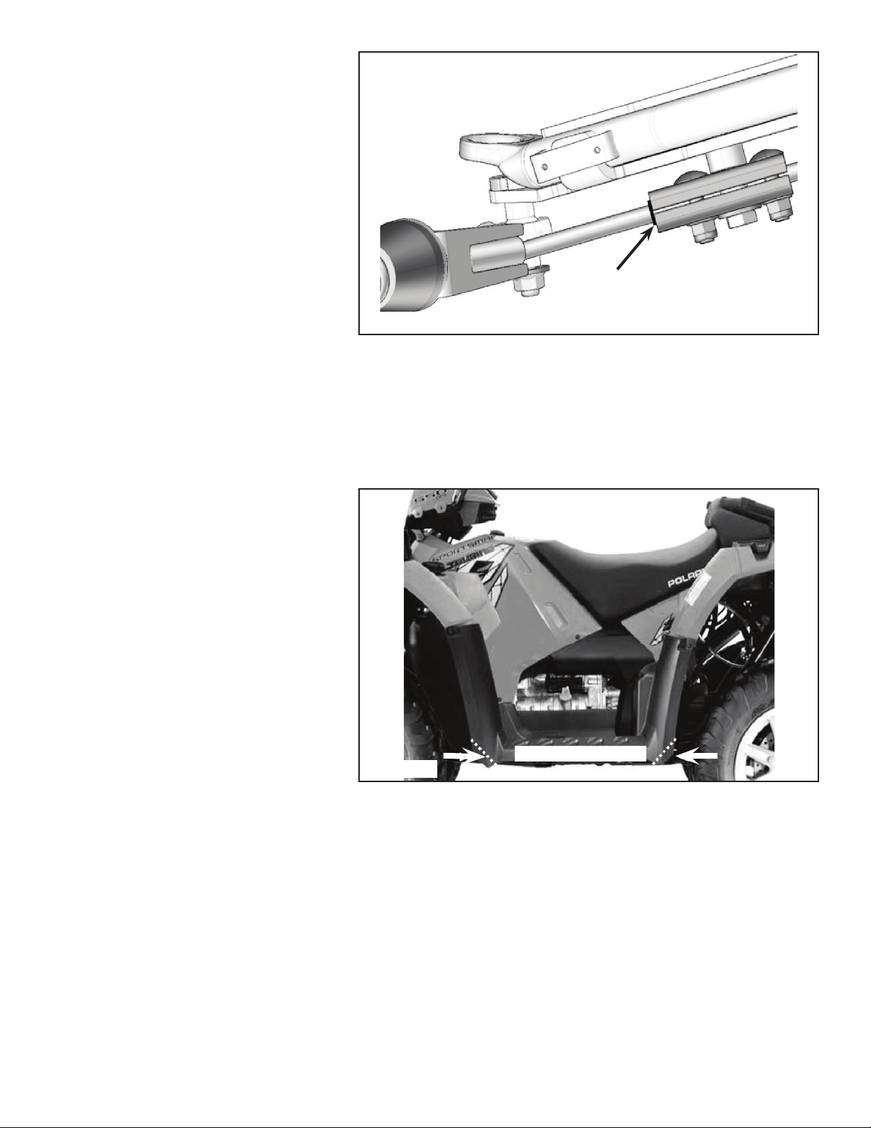
2. Verify for possible contact between the undercarriage and the lower fender. If there is contact, the fender
should be modied (cut) to avoid damage to the vehicle’s components and premature wear on rubber track.
3. For model years 2010 and later:
To prevent any contact between the
undercarriage and the mud guards,
the corners of the mud guards should
be trimmed back. This will help avoid
damage to the ATV and premature
wear on the rubber track. Figure 26
and use template illustrated in
Figure 27.
4. Lower the ATV to the ground.
Figure 26
TRIM
-15-
Page 16

Figure 27
Front
Rear
Figure 27a
ADJUSTMENTS:
CAUTION: The track systems are designed to provide the best performance in terms of
traction and oatability. Adjustments such alignment, track tension, and angle of attack are
necessary and mandatory for optimal performance of the systems. For more information
on these adjustments, refer to the ADJUSTMENT RECOMMENDATIONS or USER MANUAL
provided with the installation kit specic to the vehicle.
P/N 9924981 Rev 01 12/13
-16-
 Loading...