

Page 1

C1500 ORP or pH Controller
120V/240V
O WNER’S MANUAL
Page 2

IMPORTANT SAFETY INFORMATION
When installing and using this electrical equipment, basic safety
precautions should always be followed including the following:
READ AND FOLLOW ALL INSTALLATION INSTRUCTIONS.
Installation of this equipment should be performed by a licensed
electrician and conform to all National Electric Code (NEC),
state and local codes. Installations in Canada must comply to
CEC requirements.
WARNING:To reduce the risk of electrical shock:
• Turn off or disconnect the power source before installing,
opening the door, or adjusting the internal workings of
the controller.
• Install all electrical equipment at least 10 feet (3 m) from
inside wall of pool or spa.
• Connect this device only to a grounding-type receptacle
protected by a ground-fault circuit interrupter (GFCI).
• Do not use an extension cord, connect the controller
directly into the outlet. Do not bury the cord.
WARNING:To reduce risk of injury, do not permit children to use
this product unless they are closely supervised at all times.
For proper operation, it is imperative that the system has proper
flow past the sensors when the pool filtration system is running.
When automating a body of water, size the feeders so desired
levels can be attained in short operating cycles. If feeders are
unable to keep up with demand within a short time frame,
automation becomes ineffective.
Always test and adjust sanitizer and pH to acceptable levels
before activating a new system. Automated chemical controllers
are designed to maintain water chemistry, not balance the pool.
While the system is feeding, inaccurate sanitizer/pH levels may
be displayed because the system is still circulating the chemical.
ve precautions for electrostatic
Obser
.
vices
sensitiv
VE THESE INSTRUCTIONS.
SA
e de
Page 3

Table of Contents
Specifications
Introduction . . . . . . . . . . . . . . . . . . . . . . . . . . . . . . . . . . . . . . . . .2
Components . . . . . . . . . . . . . . . . . . . . . . . . . . . . . . . . . . . .2
Optional FlowCell/Flow Switch . . . . . . . . . . . . . . . . . . . . . .3
Installation . . . . . . . . . . . . . . . . . . . . . . . . . . . . . . . . . . . . . . . . . .4
Feed Systems . . . . . . . . . . . . . . . . . . . . . . . . . . . . . . . . . . .4
Controller . . . . . . . . . . . . . . . . . . . . . . . . . . . . . . . . . . . . . . .5
Sensor . . . . . . . . . . . . . . . . . . . . . . . . . . . . . . . . . . . . . . . .6
Electrical Connections . . . . . . . . . . . . . . . . . . . . . . . . . . . . .7
Operation . . . . . . . . . . . . . . . . . . . . . . . . . . . . . . . . . . . . . . . . . .8
System Startup . . . . . . . . . . . . . . . . . . . . . . . . . . . . . . . . . .8
Controller Displays . . . . . . . . . . . . . . . . . . . . . . . . . . . . . . . 8
System Operation . . . . . . . . . . . . . . . . . . . . . . . . . . . . . . .12
Maintenance . . . . . . . . . . . . . . . . . . . . . . . . . . . . . . . . . . . . . . .14
Cleaning the Sensor Tips . . . . . . . . . . . . . . . . . . . . . . . . .14
Checking the ORP Sensor . . . . . . . . . . . . . . . . . . . . . . . .14
Checking the pH Sensor . . . . . . . . . . . . . . . . . . . . . . . . . .15
Winterizing . . . . . . . . . . . . . . . . . . . . . . . . . . . . . . . . . . . . .15
Warranty . . . . . . . . . . . . . . . . . . . . . . . . . . . . . . . . . . . . . . . . . .16
Appendix . . . . . . . . . . . . . . . . . . . . . . . . . . . . . . . . . . . . . . . . . .18
Page 4

Specifications
pH Control Range: 7.0 to 8.0
ORP Control Range: 200 to 900
Input Power: • 120 VAC 50/60 Hz, GFCI source required
• 240 VAC 50/60 Hz capable
• 8A fuse for 120V, 4A fuse for 240V
Controller Power: Less than .5 amp internally fused
Output Power: • 120 VAC 50/60 Hz
• 240 VAC 50/60 Hz capable
• 8A fuse for 120V, 4A fuse for 240V
Display: LCD, 2-line character display
Operating Temp: 40 - 120° F
Sensors: • pH: glass combination with 10' cable
• ORP: platinum combination with 10' cable
Inputs: ORP & pH sensors; BNC connectors
Flow detection
Outputs: • ORP/pH Feeder - High Voltage
120 VAC 50/60 Hz (with 120V input)
240 VAC 50/60 Hz (with 240V input)
8A fuse for 120, 4A fuse for 240 on-board
• ORP/pH Feeder – Low Voltage, 24V
Page 5
Introduction
O
R
P
p
H
2
3
ENTER
1
Chemical Automation System
Congratulations on the purchase of your new ORP/pH controller
and thank you for choosing Polaris. The Polaris Watermatic
C1500 Controller automatically monitors and maintains either
the sanitizer level or the pH balance in swimming pools, spas, or
any circulating water system that requires water chemistry
management. Designed for easy installation and simple
operation, it can be used with liquid feed pumps, granular
feeders, tablet erosion feeders, and ozone generators. It is not
warranted or recommended for use with chlorine gas systems.
During the filtration cycle, the controller maintains sanitizer
levels or pH balance by constantly measuring the OxidationReduction-Potential (ORP) and pH balance of the water. If the
sanitizer level (ORP) or pH falls below a predetermined set
point, the controller activates the chemical feeder.
Settings and measurements are displayed on an easy-to-read
LCD text screen and adjustments are made via a touch key pad.
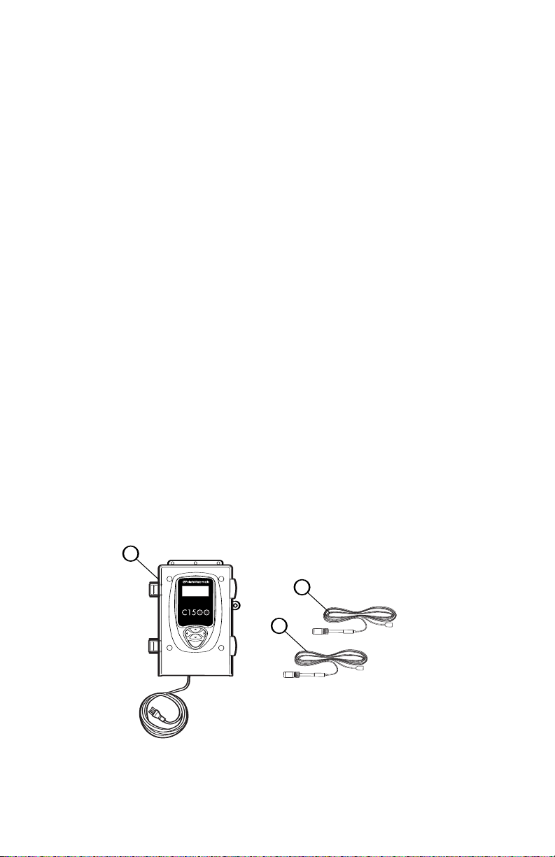
Watermatic C1500 Components
1. C1500 ORP/pH Controller
2. ORP Sensor
3. pH Sensor
2
Page 6
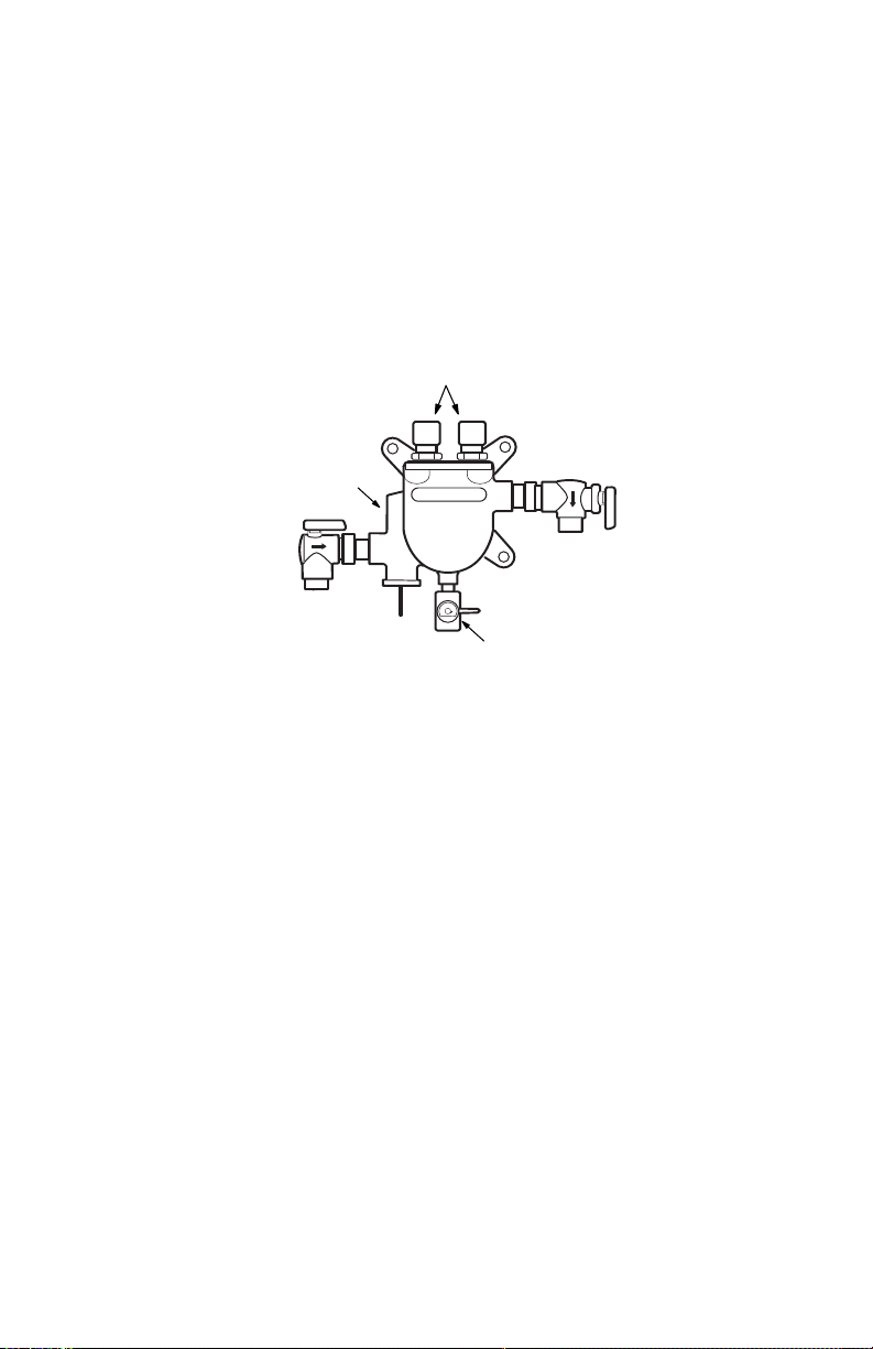
Optional Flow Cell/Flow Switch Assembly
Sample
Port
Compression Fittings
for Sensors
Flow Switch/
Flow Indicator
The flow cell houses the sensors and provides a sample port
for manual testing. It also contains an integrated flow switch/flow
indicator that prevents the feeder from feeding if there is
insufficient flow. If flow is insufficient, a warning message will
appear on the screen.
Contact an authorized Polaris dealer to order, part #9-700.
3
Page 7
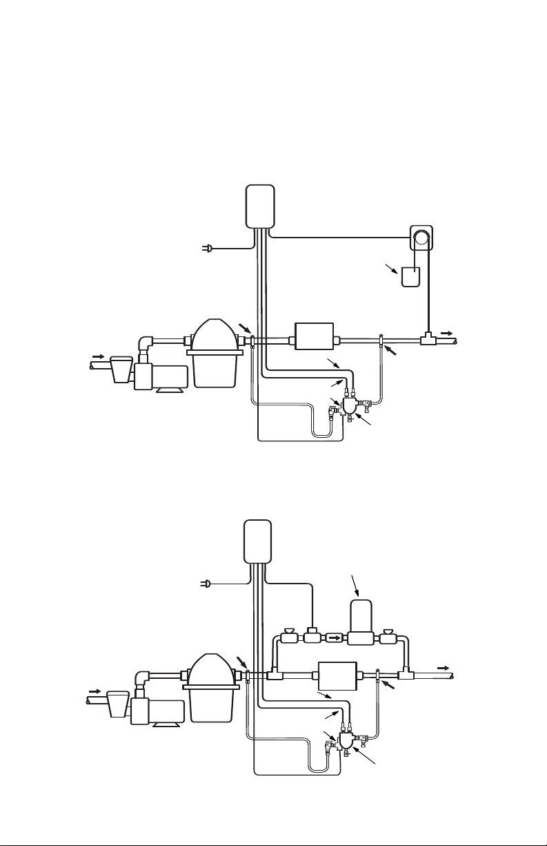
Installation
Feed Pump
B
A
From
Pool
Optional
Flow Cell
pH Sensor
ORP Sensor
Filter
Heater
Pump
120/240 VAC
GFCI Receptacle
To
Pool
Chemical
Tank
Controller
Flow Switch
B
A
From
Pool
Optional
Flow Cell
pH Sensor
ORP Sensor
Filter
Heater
Pump
To
Pool
Controller
Check
Valve
24V Solenoid
Valve
Flow Switch
Erosion
Feeder
120/240 VAC
GFCI Source
Install the chemical pump and erosion feed systems as shown.
If the model differs from these systems, refer to the installation
manual provided with it for the appropriate installation methods.
Liquid Feeder
If using an acid feed system, the insertion point must be down
stream of all equipment.
Erosion Feeder
4
Page 8
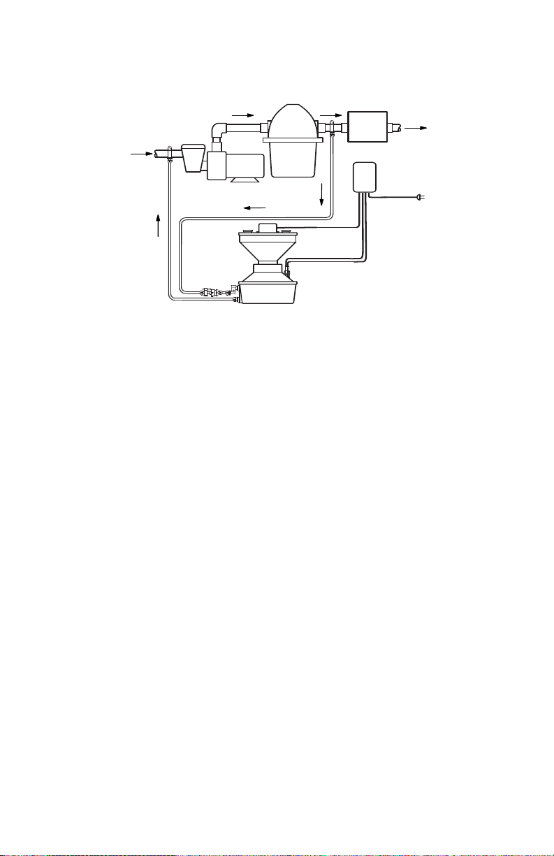
ORP
pH
Pump
Hopper
Tank
Heater
Controller
Filter
To
Pool
From
Pool
WATERMATIC
G1000
Heater
120/240 VAC
G
FCI Source
Granular Feeder
Do not install granular feeders below the pool water level.
Controller Installation
Before installing the controller, do a site assessment to consider
where and how you will mount the unit. The controller should be
mounted on a wall or other flat surface within eight feet of the
feeder, at least ten feet away from the edge of the water and
within six feet of the GFCI power source. Use mounting screws
or anchors to mount the controller.
5
Page 9

Sensor Installation
Controller
Compression
Fitting
Sensor Tip
ENTER
Chemical Automation System
ORP
OR
P
OR
P
Sensors
with
O-rings
Controller
Compression
Fitting
PVC Tee
Sensor Tip
ORP
ENTER
C
hemical Automation System
Unpack the sensors and remove the protective bottle and
o-rings. Set aside the o-rings. Save the bottles for winterizing
or reshipping.
Flow Cell
Remove the compression fitting
nut from the flow cell and slide it up
onto the sensor. Slide o-ring from
the bottle onto the sensor. Insert
the sensor into the compression
fitting on the flow cell assembly.
The sensor tip should extend below
the water line in the flow cell.
Granular Feeder
Insert the sensors with the o-rings
into the holes on the feeder tank.
The sensor tips should be covered
with at least 1" of water.
In-line
Install 1/2" female threaded PVC
tee into the return line. Screw the
compression fitting into the tee.
Slide an o-ring onto the sensor.
Insert sensor with o-ring into the
fitting. Sensor tip should be below
the water line in the pipe.
Hand-tighten the nuts of the compression fittings, do not use
a wrench. Route sensor cables to the controller, coiling extra
cable externally, not in the controller box.
6
Page 10

Electrical Connections
Grommets
Wire Clamp
For SMALL
Diameter
Cables:
Bend grommet
to open slot
For LARGE
Diameter
Cables:
Tear out grommet center
Controller
Housing
Sensors
BNC Connections
Flow
Switch
Wire
Clamp
Grommet
120/240V Output
to Feeder
24V Output
to Feeder
To complete electrical connects:
1. Ensure power is disconnected. Open the controller door.
2. Remove the wire clamp.
3. Strip wire leads (maximum of 3/8") from ORP and pH
feeders. To facilitate wire hook-up, remove output terminal
block from circuit board. Attach feeder AC output leads to
terminal block. Note the orientation of the leads (ground, line
and neutral). Reinstall terminal block.
4. If using a Flow Cell, remove the jumper on the Flow terminal
block and attach leads from the Flow Switch to the terminal.
5. Attach the pH and ORP sensor BNC connectors to the board.
6. Route connections through housing grommets using the
appropriate grommet for the wire size.
7. Reinstall wire clamp and close the door.
7
Page 11
Operation
ENTER
Key Pad
Current ORP
Chemical Automation System
ORP 600 OK
pH 7.8
Current pH
Status
System Startup
Do not add chemicals to the feeder until completing the following
startup operations.
1. Use a DPD test kit and fresh phenol red solution to test the
water’s sanitizer level and pH, then manually adjust the
water to acceptable levels.
2. With the controller power off, turn on the filter pump to check
for leaks and proper flow.
3. Plug controller power cord into GFCI receptacle. The LCD
display screen should illuminate.
3. Review controller displays and set the controller functions.
Adjust the defaults, if necessary, to match the application.
Controller Displays
ORP and pH measurements and settings are displayed on the
controller’s LCD screen. Adjustments to settings are made with
the key pad. Use the left and right arrow keys to move through
the screens and the up or down keys to adjust the settings.
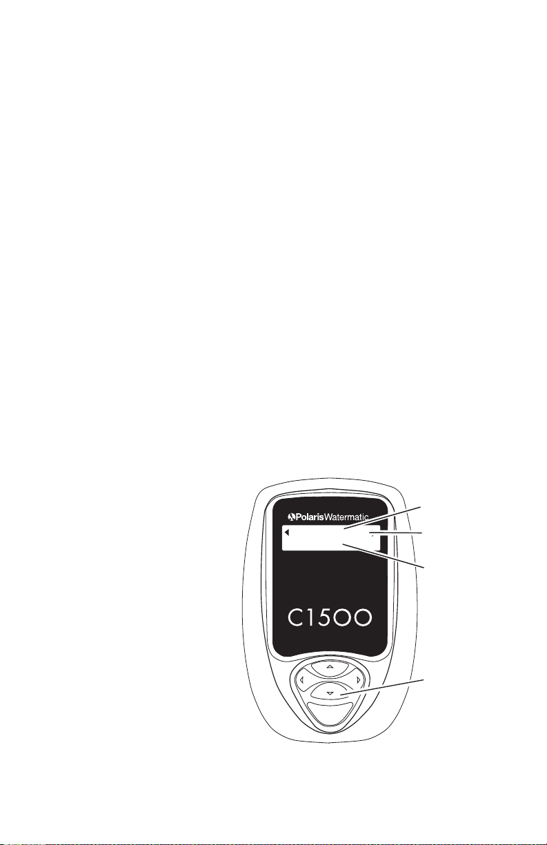
Main Screen
The Main screen shows
the current ORP and pH
readings, and a status
message.
The status messages
are: “Feeding” when
chemical is being
dispensed, “OK” when
sensor readings match
the desired levels, no
display or blank during
a feed delay cycle or
an alert notice.
8
Page 12

Feed ORP or pH
Feed ORP or pH
ORP
Feeder Type
Granular
Feed Time
5 sec
Feed Delay
10 min
Configures the controller as
either an ORP feeder or a
pH feeder. Only one may
be selected.
Feeder Type
Specifies the type of feeder
being used. Depending on the
feeder selected, Feed Time and
Feed Delay settings will change
to the feeder specific defaults
outlined in the Appendix.
Types of feeders available:
• Granular
• Liquid (Use for Ozone generators)
• Erosion HP (line voltage) solenoid
• Erosion LP (24V) solenoid
Acid/Base
Displayed only if ”Feed pH” is chosen. Designates whether the
controller maintains the pH below the set point (acid) or above
the set point (base).
Feed Time
Designates the amount of time
the feeder is activated.The
preset defaults for specific
feeder types (see Appendix)
can be adjusted as necessary.
Feed Delay
Designates a minimum time
between feeding. This option is
ed if “Continuous”
not displa
feed is selected. All feeders
def
be adjusted from 1-99 min
y
ault to 10 minutes but can
utes
.
9
Page 13

Overfeed
Overfeed
99 min
Manual Feed
Press Enter
ORP 600 Feeding
pH 7.8
Audible Alarm
On
Displays only when Feed Time
is set to "Continuous." Sets a
maximum feed time to prevent
overfeeding caused by an
empty chemical tank or tubing
leak. Defaults to 99 minutes, but
is selectable from 1-99 minutes.
Manual Feed
Activates either the ORP or
pH feeder to facilitate testing
of connections and feed cycles.
To manually feed, press the
<Enter> key.
When manually feeding, the
Main screen will display a
“feeding” status message.
Audible Alarm
Toggles the controller’s
internal audible alarm
on or off.
The alarm sounds and an
alert message is displayed
on the screen for the following
circumstances:
High Alert - When ORP is above 900 or pH is above 8.0 for ten
consecutive minutes.
Low Alert - When ORP is below 200 or pH below 7.0 for ten
consecutive minutes.
When the alert condition is corrected, the controller will wait ten
minutes then automatically clear the alert. After a two-minute
delay, it will activate the feeder as needed.
witch is installed and there is insufficient flow
w cell/flo
If a flo
er the sensors
v
o
w s
, a
No Flowaler
t will be signaled on the screen.
10
Page 14

ORP or PH Setpoint
ORP Setpoint
600
PH Calibration
7.5 Press Enter
PH Setpoint
7.5
Designates the desired level of sanitizer (ORP) or pH depending
on feeding system.
Feed ORP
Set ORP to any value between
200 and 800, in increments of
10. The default is 600.
Feed pH
Set pH to any value between
7.0 and 8.2, in increments of
0.1 pH. The default is 7.5.
The controller displays direct ORP readings and the control is
based on this reading, not parts per million (ppm). While ORP
indicates the effectiveness of the sanitizer, it does not directly
correlate to a ppm reading. Use a DPD test kit to measure the
free chlorine. If you need more or less sanitizer, adjust the set
point up or down accordingly.
Note: The ORP reading is not linear. An adjustment from 700
to 750 could increase the sanitizer level by several ppm. The
World Health Organization suggests maintaining an ORP at
or above 650.
Calibration
Allows user to adjust the pH
sensor reading to match the
actual pH of the water.
To calibrate the pH, check
the pH of the water at the
probe location using a high-quality manual test kit with fresh
phenol red solution. If the pH reading on screen is different
than the actual, use the up/down curser to select the proper pH.
Press <Enter> to save the entry. Using the left/right arrow key,
return to the Main screen and verify that pH displays accurately.
11
Page 15

System Operation
When system setup is complete:
1. Fill feeder with chemical.
2. Turn on the pool circulation system. A 2-minute delay at
startup allows air to be purged from the feeders and the
sensors to stabilize.
3. Manually feed one cycle to ensure proper operation. ORP
or pH feed messages (“Feeding,” “OK,” blank or an alert) will
display under Status.
4. Allow the system to operate for a few days. With the filtration
system running, retest the levels and adjust the set points
if necessary.
To place the controller in
control, sensing, etc. but power is still on) press and hold the
<Enter> key for five seconds. Press any key to reactivate.
To service the controller, unplug the controller to disconnect
the power.
Standby Mode (disables feeder
12
Page 16

13
Page 17

Maintenance
Cleaning the Sensor Tips
Clean the sensor tips once a month to ensure accurate
readings. When dirty, the sensors can read a lower than actual
sanitizer/pH level and can cause too much sanitizer/pH to
be dispensed.
Note: A sensor tip coated with calcium scale will not look dirty.
To clean the sensor tip.
1. Turn off the controller. Turn off the filtration system or close
the valves to isolate the sensor.
2. Remove the sensor from the compression fitting.
3. Swirl the tip for five seconds in muriatic acid (diluted 5 to 1)
or white vinegar and rinse it in water. Do not touch, wipe or
brush the end of the sensor. For commercial pools and
spas, every third cleaning, swirl the sensor tip in a solution
of liquid soap and water. Rinse with water.
4. Reinstall the sensor and turn on the controller.
5. Allow the controller to operate for a few minutes to get an
accurate reading. Adjust the setting if necessary.
Checking the ORP Sensor
The ORP sensor should be checked every six months or
anytime the feeder oversanitizes the water.
1. Clean the sensor tip.
2. Put the sensor in a clean glass of tap water.This should give
a reading of between 200 and 400. Adding a pinch of
Dichlor or Trichlor should cause the ORP level to jump
to between 750 and 800. If Dichlor or Trichlor are not
available and a sanitizer with a high pH such as calcium
hypochlorite or liquid chlorine (sodium hypochlorite) is used,
the ORP level may only rise to between 650 and 750.
3. If the sensor does not respond as indicated, the sensor
should be replaced.
14
Page 18

Checking the pH Sensor
The pH sensor should be checked every six months or anytime
the pH goes out of range.
1. Clean the sensor.
2. Place the sensor in a clean glass of tap water. Add a small
amount of acid to the glass. The pH reading should drop.
Place the sensor in any solution with a pH above 7.5.The
pH reading should rise.
3. If the sensor does not respond as indicated, the sensor
should be replaced.
Winterizing
If the system is subject to extended shutdowns or is located in
colder climates, it is important to winterize the system.
1. Turn off the main power to the controller.
2. Gently remove the sensors and store them in a protective
cap or bottle filled with a liquid solution of one teaspoon salt
and three teaspoons water. Mix the solution thoroughly and
make sure the solution completely covers the tip of the
sensors. Store the sensors in a warm place. Do not expose
sensors to freezing temperatures.
3. If installed, drain the water from the flow cell/flow switch.
15
Page 19

Warranty
Polaris Watermatic C1500 ORP or pH Controller
This limited warranty is extended to the original consumer
purchaser of this Polaris Watermatic Controller manufactured by
Polaris Pool Systems, Inc. ("Polaris"), 2620 Commerce Way,
Vista, CA 92081-8438, USA.
Polaris warrants the Watermatic Controller, including all parts
and components thereof, to be free of defects in material and
workmanship. For questions regarding your Polaris Watermatic
Controller, please call or write us. Be sure to provide the serial
number of your unit.
The warranty commences on the date of installation of the
controller and shall remain in effect for a period of one (1) year
from the date of purchase as established by proof of purchase or
two (2) years from the date of manufacture of the controller as
established by the serial number, whichever is earlier.
This limited warranty does not apply if the failure is caused or
contributed by any of the following: improper handling, improper
storage, abuse, unsuitable application of the unit, lack of
reasonable and necessary maintenance, winter freezing or
repairs made or attempted by other than Polaris or one of its
Authorized Service Centers. Polaris will repair or replace, at its
option, a unit, part or component proved to be defective within
the warranty period and under the conditions of the warranty.
Unless local repair is authorized, the consumer must deliver or
ship the unit or the warranted parts or components, freight
prepaid to the nearest Polaris Authorized Service Center or
return it freight prepaid (after proper authorization) to the plant of
manufacture. Authorization to return a unit to the plant of
manufacture must be obtained from the Polaris Customer
Service Department. For your convenience, please check with
your dealer for the local procedure before exercising this
If further directions or instructions should be required,
.
anty
arr
w
contact the Customer Service Department at 1-800-VACSWEEP (USA and Canada only) or 760-599-9600. Be sure to
insure y
our shipments against loss or damage during transit.
16
Page 20

Polaris is not responsible for the cost of removal of the unit,
damages occurring during removal or due to removal, any other
expenses incurred in shipping the unit or parts to or from the
factory or its Authorized Service Centers, or the installation of
the repaired or replacement unit. The consumer must bear these
expenses. This warranty does not cover repair of a unit except at
our factory or a Polaris Authorized Service Center.
REPAIR OR REPLACEMENT AS PROVIDED UNDER THIS
LIMITED WARRANTY IS THE EXCLUSIVE REMEDY OF THE
CONSUMER. THIS LIMITED WARRANTY IS IN LIEU OF ALL
OTHER WARRANTIES, EXPRESS OR IMPLIED, INCLUDING
THE IMPLIED WARRANTIES OF MERCHANTABILITY AND
FITNESS FOR A PARTICULAR PURPOSE, AND ALL SUCH
OTHER WARRANTIES ARE DISCLAIMED EXCEPT TO THE
EXTENT ANY IMPLIED WARRANTY MAY BE IMPOSED BY
STATE CONSUMER LAW. ANY SUCH IMPLIED WARRANTY
IMPOSED BY STATE CONSUMER LAW IS LIMITED IN
DURATION TO ONE (1) YEAR FROM DATE OF PURCHASE. IN
NO EVENT SHALL POLARIS BE LIABLE FOR INCIDENTAL
OR CONSEQUENTIAL DAMAGES OF ANY NATURE OR KIND
OR FOR DAMAGES TO PERSONS OR PROPERTY,
INCLUDING ANY DAMAGE RESULTING FROM THE USE OF
THE POLARIS WATERMATIC CONTROLLER. THE ONLY
REMEDY PROVIDED TO YOU UNDER AN APPLICABLE
IMPLIED WARRANTY AND THE LIMITED WARRANTY SET
FORTH ABOVE SHALL BE THE REMEDIES EXPRESSLY
PROVIDED FOR UNDER THIS LIMITED WARRANTY.
This limited warranty gives you specific legal rights. You may
also have other rights that may vary from state to state. Some
states do not allow limitations on how long an implied warranty
lasts, or the exclusion or limitation of incidental or consequential
damages, so the above limitations may not apply to you.
This limited warranty is valid only in the United States of
America and Canada, and it does not apply to Polaris
Watermatic Controllers sold or installed in any other country.
17
Page 21

Appendix
Feed Times and Delay Times
When the ORP or pH feeder type is specified during setup, the
Feed Time and Delay Time settings change to the feeder
specific defaults listed below. The options listed are available to
customize for the specific application.
After allowing the system to run for a few days, adjust the ORP
or pH settings as needed. Lengthen the feed cycle if the water is
undersanitized or shorten it if the water is oversanitized. Shorten
the delay time if the feeder cannot keep up with demand.
ular Feeder
Gran
Feed Time Delay Time Overfeed
(Min.) (Min.)
Options 0.5, 1, 2, 3, 4, 5 Sec. 1 – 99 N/A
Defaults 5 Sec. 10
Liquid Feeder (Use for ozone generators)
Feed Time Delay Time Overfeed
(Min.) (Min.)
Options Continuous Off 1 - 99
5, 10, 15, 20, 30 Sec. 1 - 99 Off
1, 2, 3, 4, 5, 10, 15 Min.
Defaults 10 Min. 10 Off
Erosion Feeder
Feed Time Delay Time Overfeed
(Min.) (Min.)
Options: Continuous Off 1 - 99
5, 10, 15, 20, 30 Sec. 1 - 99 Off
1, 2, 3, 4, 5, 10, 15 Min.
Default 10 Min 10 Off
Erosion LP = Low power (24V) solenoid
Erosion HP = High po
wer (line voltage) solenoid
18
Page 22

Alerts and Alarms
The following alert conditions will sound the audible alarm:
• High PH Alert
• Low PH Alert
• High ORP Alert
• Low ORP Alert
• PH Overfeed
• ORP Overfeed
The following alert conditions will not sound the Alarm:
• No Flow
• 2-Minute Flow Delay
19
Page 23

Page 24

©2006 Polaris Pool Systems, Inc. All rights reserved. TL-448 6/06
 Loading...