

Page 1

BRUTUS™
BRUTUS™ HD
BRUTUS™ HD
Owner's Manual
for Maintenance and Safety
PTO
Page 2

WELCOME
Thank you for purchasing a POLARIS vehicle, and wel come to our world- wide family of POLARIS owners. We proudly produce
an exciting line of utility and recreational products.
• Snowmobiles
• All-terrain vehicles (ATVs)
• BRUTUS
• RANGER® utility vehicles
• Victory® motorcycles®
• Low Emission Vehicles (LEVs)
W e be lieve POLARIS sets a sta ndard of exce llence for all utility and recreat ional vehic les manufact ured in the worl d today. Many
years of experience have gone into the engineering, design, and development of your POLARIS vehicle, making it the finest
machine we’ve ever produced.
For safe and enjoyab le oper at ion of your vehicle, be su re to follow the instr uct io ns and recommendations i n th is owner’s manual .
Your manual contains instructions for minor maintenance, but information about major repairs is outlined in the POLARIS Service Manual and should be performed only by a Factory Certified Master Service Dealer® (MSD) Technician.
Your POLARIS dealer knows your vehicle best and is interes ted in your total satis fa ct ion . Be sure to return to your dealership for
all of your service needs during, and after, the warranty period.
We also take great pride in our complete line of apparel, parts and accessories, available through our online store at www.purepolaris.com. Have your accessories and clothing delivered right to your door!
™ utility vehicles
1
Page 3

POLARIS is registered trademark of and BRUTUS is a trademarks of POLARIS Industries Inc.
Copyright 2013 POLARIS Sales Inc. All information contained within this publication is based on the latest product information
at the time of publication. Due to constant improvements in the design and quality of production components, some minor discrepancies may result between the actual vehicle and the information presented in this publication. Depictions and/or procedures
in this publication are intended for reference use only. No liability can be accepted for omissions or inaccuracies. Any reprinting
or reuse of the depictions and/or procedures contained within, whether whole or in part, is expressly prohibited.
The original instructions for this vehicle are in English. Other languages are provided as translations of the original instructions.
Printed in U.S.A.
2013 BRUTUS Diesel Owner’s Manual
P/N 9924341
2
Page 4

Table of Con tents
Introduction. . . . . . . . . . . . . . . . . . . . . . . . .4
Safety . . . . . . . . . . . . . . . . . . . . . . . . . . . . .6
Features And Controls . . . . . . . . . . . . . . .18
Operation . . . . . . . . . . . . . . . . . . . . . . . . .34
Attachment Arm . . . . . . . . . . . . . . . . . . . .70
PTO System . . . . . . . . . . . . . . . . . . . . . . .74
Emission Control Systems . . . . . . . . . . . .76
Maintenance . . . . . . . . . . . . . . . . . . . . . . .77
Specifications . . . . . . . . . . . . . . . . . . . . .125
Polaris Products . . . . . . . . . . . . . . . . . . .128
Troubleshooting . . . . . . . . . . . . . . . . . . .130
Warranties. . . . . . . . . . . . . . . . . . . . . . . .131
Maintenance Log . . . . . . . . . . . . . . . . . .136
Index. . . . . . . . . . . . . . . . . . . . . . . . . . . .137
3
Page 5

INTRODUCTION
WARNING
Failure to follow the warnings contained in this manual can result in
severe injury or death.
A POLARIS BRUTUS is not a toy and can be hazardous to operate.
This vehicle handles differently than other vehicles, such as
motorcycles and cars. A collision or rollover can occur quickly, even
during routine maneuvers like turning, or driving on hills or over
obstacles, if you fail to take proper precautions.
• Read this owner’s manual. Understand all safety warnings,
precautions and operating procedures before operating the
vehicle. Keep this manual with the vehicle.
• Never permit a guest to operate this vehicle unless the guest has
read this manual and all product labels.
• Always keep hands and feet inside the vehicle at all times
• The Polaris BRUTUS is not intended for on-highway use. Driver
must be at least 16 years old with a valid driver’s license to
operate. Passengers m us t b e a t least 12 years ol d a nd tall enough
to sit with feet firmly on the floor. All SxS drivers should take a
safety training course. Polaris recommends that drivers and
passengers wear helmets, eye protection, and protective clothing,
especially for trail riding and other recreational use. Always wear
seat belts. Be particularly careful on difficult terrain. Never engage
in stunt driving, and avoid excessive speeds and sharp turns.
Riding and alcohol/drugs don’t mix. Check local laws before riding
trails.
The BRUTUS is an off-r oad vehicl e. Familiari ze yourse lf with
all laws and regulations concerning the operation of this vehicle in your area.
The following signal words and symbols appear throughout
this manual and on y our vehicle. Your safety is involved when
these words and symbols are use d. Become familiar with their
meanings before reading the manual.
Safety Symbols and Signal Words
The following signal words and symbols appear throughout
this manual. Your safety and the safety of others is involved
when these words and symbols are used. Become familiar with
their meanings before reading the manual.
The safety alert symbol indicates a potential personal injury hazard.
DANGER
A DANGER ind icates a hazardous situation that, if not avoided, will
result in death or serious injury.
WARNING
A WARNING indicates a hazardous situation that, if not avoided,
could result in death or serious injury.
CAUTION
A CAUTION indicates a hazar dous situat ion that, if not avoided, cou ld
result in minor or moderate injury.
NOTICE
A NOTICE indicates a situation that could result in property damage.
The Prohibition Safety Si gn indicates an ac tion NOT to tak e
in order to avoid a hazard.
The Mandatory Action Sign indicates an action that NEEDS
to be taken to avoid a hazard.
4
Page 6
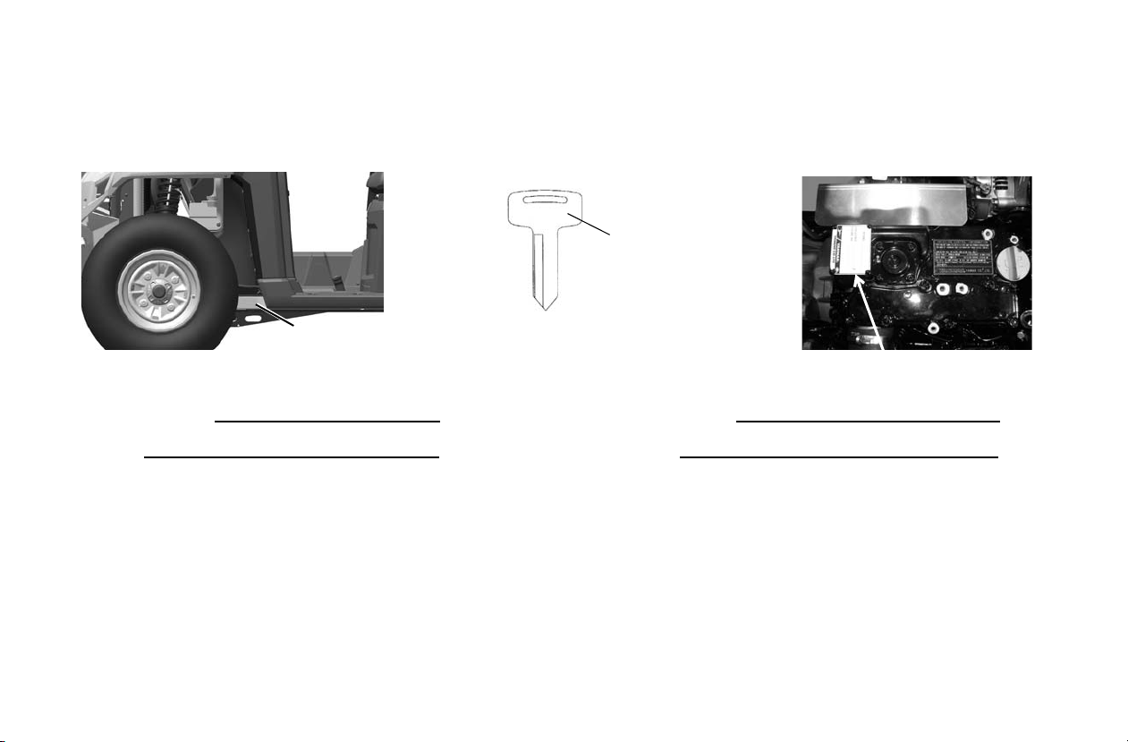
Vehicle Identification Numbers
Engine Serial Number
Key
Number
####
VIN
Record your vehicle's identification numbers and key number
in the spaces provided. Remove the spare key and store it in a
safe place. An ignit ion key can be duplicated only by orde ri ng
INTRODUCTION
a POLARIS key blank (using your key number) and mating it
with one of your existing keys. The ignition switch must be
replaced if all keys are lost
.
Vehicle Model Number:
Frame VIN:
European Vibration and Noise
The driver-perceived noise and hand/arm and whole body
vibration levels of this machinery is measured per prEN
15997.
The operating conditions of the machinery during testing:
The vehicles were i n like-new condition. Th e environ ment was
controlled as indicated by the test procedure(s).
The uncertainty of vibration exposure measurement is depen-
dent on many factors, including:
Engine Serial Number:
Key Number:
• Instrument and calibration uncertainty
• Variations in the machine such as wear of components
• Variation of machine operators such as experience or physique
• Ability of the worke r to reproduce typical work during mea surements
• Environmental factors such as ambient noise or temperature
5
Page 7
Safety
PTO Warning
(If Equipped)
Discretionary
Warning
Age 16
Warning
Shift
Caution
To Start Engine /
To Leave vehicle
Attachment Arm Warning
(If Equipped)
Seat Switch Warning
(If Equipped With PTO)
Towing Warning
Discretionary
Warning
Rotating Fan
Warning
Safety and Information Labels
Warning labels have been placed on the vehicle for your protection. Read and follow the instructions of the labels on the
vehicle carefully. If any of the labels depicted in this manual
differ from the labels on your vehicle, always read and follow
the instructions of the labels on the vehicle.
If any label becomes illegible or comes off, contact your
POLARIS dealer to purchase a replacement. Replacement
safety labels are provided by POLARIS at no charge. The part
number is printed on the label.
6
Page 8

Safety Labels and Locations
Age 16 Warn ing
WARNING
NO OPERATOR UNDER 16
Operating this vehicle if you are under the age of 16 increases your
chance of severe injury or death.
NEVER operate this vehicle if you are under age 16 and NEVER
operate this vehicle without a valid driver’s license.
7175566
To Start Engine / To Leave Vehicle
To Start Engine
• Gear Selector must be in PARK, NEUTRAL or travel control pedal
must be in NEUTRAL.
• PTO must be OFF (If Equipped).
To Leave Vehicle
• Put gear selector in PARK.
• STOP engine.
7179357
Shift Caution
CAUTION
To avoid transmission damage, shift only when vehicle is stationary
and at idle.
7172674
Seat Switch Warning
WARNING
• Check that seat switch is properly installed and functions correctly.
• Replace switch and components if damaged or missing.
7179343
SAFETY
Discretionary Warning
WARNING
Improper vehicle use can result in Serious Injury or Death.
NEVER Operate:
• At speeds too fast for your skills or the conditions.
• After or while using Alcohol or Drugs.
• On hills steeper than 15 degrees 15°.
• On public roads, a collision can occur with a another vehicle.
• With passengers under age twelve or who cannot comfortably
reach the floor and hand holds.
• With unapproved accessori es - they may seriously affect stability.
ALWAYS:
• Wear your seat belt. Vehicle rollover could cause severe injury or
death.
• Wear eye protection and keep hands and feet in vehicle at all
times.
• Reduce speed and use extra caution when carrying passengers.
• Avoid sharp turns or turns while applying heavy throttle.
• Operate slowly in reverse - avoid sharp turns or sudden braking.
• Make sure passenger reads and understands all safety signs.
• Watch for branches or other hazards that could enter vehicle.
LOCATE AND READ OWNER’S MANUAL. FOLLOW ALL
INSTRUCTIONS AND WARNINGS.
7179169
7
Page 9

SAFETY
Safety Labels and Locations
Attachment Arm Wa rning
WARNING
Avoid Serious Injury Or Death.
• Do not excee d attachment arm rated capacity.
• Keep bystanders away. No riders on attachment.
• Keep hands and body from under attachment.
• Do not modify the attachment arm o r use una pprove d att achme nts .
7179168
Rotating Parts Warning
Rotating Parts Can Cause serious Injury Or Death
• Keep PTO shield and all guards in place.
• Keep away from moving parts.
• Keep bystanders away.
• Do not exceed the PTO speed of 2000 RPM
See Owner’s Manual For More Instructions.
.
7179185
Rotating Fan Warning
WARNING
Avoid Serious Injury Or Death .
Do not operate with shields removed.
Do not modify.
7179166
Maximum Trailer Weight Warning
WARNING
Towing An Improperly Loaded Trailer Can Cause Loss Of Control
Resulting In Serious Injury Or Death.
Maximum Tongue Weight: 150 lbs. (68 kg)
Maximum Tow Weight: 2000 lbs. (907 kg)
See Owner’s Manual For More Instructions.
7179167
8
Page 10
Safety Labels and Locations
X
Load/Passenger/Tire Pressure Warning
WARNING
FALLING OFF CARGO BOX CAN CAUSE SERIOUS INJURY OR
DEATH
• Never carry riders in cargo box.
OVERLOADING OR IMPROPER TIRE PRESSURE CAN CAUSE
TIPPING OR LOSS OF CONTROL RESULTING IN SERIOUS
INJURY OR DEATH.
• Never exceed load capacities.
• Reduce speed and allow greater distance for braking when
carrying cargo.
• Carrying tall, off-center, or un-secured loads will increase your risk
of losing control. Center and secure loads as low as possible in
box.
• Reduce speed and cargo on rough or hilly terrain.
• Check for proper tire pressure.
BRUTUS BRUTUS HD BRUTUS HDPTO
MAXIMUM CARGO BOX LOAD 1250 lbs.
ATTACHMENT ARM RATED CAPACITY 500 lbs.
TIRE PRESSURE IN PSI (KPa)
MAXIMUM WEIGHT CAPACITY INCLUDES WEIGHT OF OPERATOR,
PASSENGER, CARGO AND ACCESSORIES
Read Operation and Maintenance Manual for more detailed loading information.
(567 kg)
FRONT 10 (69)
REAR 20 (138)
1750 lbs.
(794 kg)
1250 lbs.
(567 kg)
(225 kg)
FRONT 20 (138)
REAR 20 (138)
2000 lbs.
(907 kg)
SAFETY
1250 lbs.
(567 kg)
500 lbs.
(225 kg)
FRONT 20 (138)
REAR 20 (138)
1750 lbs.
(794 kg)
9
Page 11

SAFETY
Safe Riding Gear
Always wear appropriate clothing when riding a POLARIS
vehicle. Wear protective clothing for comfort and to reduce the
chance of injury.
Eye Protection
Do not depend on eyeglasses or sunglasses for eye protection.
Whenever riding a POLARIS vehicle, always wear shatterproof goggles. POLARIS recommends wearing approved Personal Protective Equipment (PPE) bearing markings such as
VESC 8, V-8, Z87.1, or CE. Make sure protective eye wear is
kept clean.
Gloves
Wear gloves for comfort and for protection from sun, cold
weather and other elements.
Boots
Wear sturdy over-the-ankle boots. Do not ride a POLARIS
vehicle with bare feet.
Clothing
Wear long sleeves and long pants to protect arms and legs.
10
Page 12

Operator Safety
WARNING
SAFETY
Serious injury or death can result if you do not follow these
instructions and proc edures , which are outl ined i n further det ail within
your owner's manual.
• Read this manual and all labels carefully. Follow the operating procedures described.
• Never allow anyo ne unde r age 16 t o operat e this ve hicle an d
never allow anyone without a valid driver's license to operate this vehicle.
• Do not carry passengers until you have at least two hour s o f
driving experience with this vehicle.
• No person under the age of 12 may ride as a passenger in
this vehicle. Any passenger must be able to comfortably
reach the floor and hand holds.
• The driver and all passengers must wear eye protection and
seat belt at all times. All riders should also wear long
sleeves, long pants and sturdy over-the-ankle boots.
• Always keep hands and feet inside the vehicle at all times.
• Always keep both hands on t he ste ering whe el and b oth feet
on the floorboards of the vehicle during operation.
• Never permit a gu est to operate thi s vehicle unless the gue st
has read this manual and all product labels.
• To reduce tipover risk, be especially careful when encountering obstacles a nd slop es and when b raking on hills or during turns.
• This vehicle i s for of f road use onl y . Never operate on pub lic
roads. Always avoid paved surfaces.
• Never consume alcohol or drugs before or while operating
this vehicle.
• Never operate at exce ss ive speeds. Always travel at a speed
proper for the terrain, visibility and operating conditions,
and your experience.
• Never attempt jumps or other stunts.
• Always inspec t t he vehicle before each use to make sure it' s
in safe operating condition. Always follow the inspection
procedures described in this manual.
• Always travel slowly and use extra caution when operating
on unfamiliar terrain. Be alert to changing terrain.
• Never operate on excessively rough, slippery or loose terrain.
• Always follow proper procedures for turning. Practice turning at slow speeds before attempting to turn at faster speeds.
Never turn at excessive speeds.
• Always have this vehicle checked by an authorized
POLARIS dealer if it has been involved in an accident.
• Never operate this vehicle on hills too steep for the vehicle
or for your abilities. Practice on smaller hills before attempting larger hill s.
11
Page 13

SAFETY
Operator Safety
• Always follow proper procedures for climbing hills as
described in this manual. Check the terrain carefully before
attempting to climb a hill. Never climb hills with excessively slippery or loos e surf aces. Nev er mo ve the t ravel control pedal suddenly, make sudden changes of direction or
make sudden gear change s. Never go ove r the top o f a hill a t
high speed.
• Always follow the proper procedures outlined in this manual for traveling downhill and for braking on hills. Check
the terrain carefully before descending a hill. Never travel
downhill at high speed. Avoid going downhill at an angle,
which would cause the vehicle to lean sharply to one side.
Travel straight down the hill where possible.
• Always check for obstacles before operating in a new area.
Never atte mpt to operate over large o bstacles such as roc ks
or fallen trees. Always follow the proper procedures outlined in this manual when operating over obstacles.
• Always be careful of skidding or sliding. On slippery surfaces such as ice, travel slowly and exercise caution to
reduce the chance of skidding or sliding out of control.
• Never operate your ve hicle in f ast- flowin g water or i n water
deeper than that specified in this manual. Wet brakes may
have reduced stoppi ng abilit y. Test your brakes aft er leavi ng
water. If necessary, apply them lightly several times to let
friction dry out the pads.
• Always be sure there are no ob stacles or peopl e behi nd your
vehicle when opera ting i n reve rse. When it's safe to procee d
in reverse, move slowly. Avoid turning at sharp angles in
reverse.
• Always use the proper size and type of tires specified in this
manual. Alw ays maintain proper tire pressure as specified
on safety lab els.
• Never modify this vehicle through improper installation or
use of accessories.
• Never exceed the s tated load ca pacity for th is vehicle. Ca rgo
should be properly distributed and securely attached.
Reduce speed and follow the instructions in this manua l for
hauling cargo, with attach ments insta lled or pull ing a traile r.
Allow a greater distance for braking. Keep the attachment
arm low (if equipped) and slow down when turning.
• Disengage PTO (if equipped), put the gear selector in
PARK, stop the engine and make sure all rotating components are stopped before exiting utility vehicle.
• Always stop the engine before refueling. Remove flammable material co ntainers f rom the box before fi lling them wi th
fuel. Make sure the refueling area is well ventilated and free
of any source of flame or sparks. Fuel is extremely flammable. See page 38 for fuel safety warnings.
• Always remove the ignition key when the vehicle is not in
use to prevent unauthorized use or accidental starting.
FOR MORE INFORMATION ABOUT SAFETY, call
POLARIS at 1-800-342-3764.
12
Page 14

Operator Safety
WARNING
Equipment Modifications
We strongly recommend that consumers do not install on a
POLARIS BRUTUS any equipment that may increase the
speed or power of the ve hicle, or make any other modification s
to the vehicle for these purposes. Any modifications to the
original equipment of the vehicle create a substantial safety
hazard and increase the risk of bodily injury.
The warranty on your POLARIS BRUTUS is terminated if
any equipment has been added to the vehicle, or if any modifications have been made to the vehicle, that increase its speed
or power.
The addition of certain accessories, including (but not limited
to) mowers, blades, tires, spraye rs, or large racks, may change
the handling characteristics of the vehicle. Use only
POLARIS-approved accessories and attachments, and familiarize your self with their function and effect on the vehic l e.
Failure to operate the BRU TUS properly can result in a collis ion , loss
of control, accident or overturn, which may result in serious injury or
death. Heed all safety w arnings outlin ed in this sec tion of the ow ner’s
manual. See the OPERATION section of the owner’s manual for
proper operating procedures.
SAFETY
Age Restrictions
This vehicle is an ADULT
VEHICLE ONL Y. NEVER operate
this vehicle if you are under age
16 and NEVER operate wi tho ut a
valid driver’s license.
No person under the age of 12
may ride as a passenger in this
vehicle. Any passenger must be
able to comfortably reach the
floor and hand holds.
Operating Without
Instruction
Operating this vehicle without
proper instruction increases the
risk of an accident. The operator
must understand how to operate
the vehicle properly in different
situations and on different types of
terrain.
All operators must read and
understand the Own er' s Ma nua l
and all warning and instruction labels before operating the vehicle.
13
Page 15
SAFETY
Operator Safety
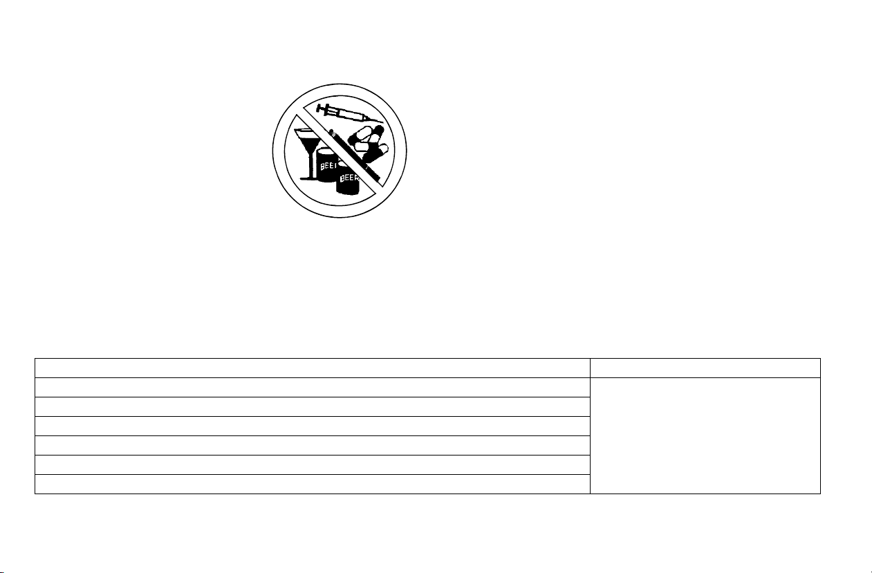
Using Alcohol or Drugs
Operating the vehicle afte r
consuming alcohol or drugs could
adversely affect operator judgment,
reaction time, balance and
perception.
Never drink alcohol or use drugs or
medications before or while
operating this vehicle.
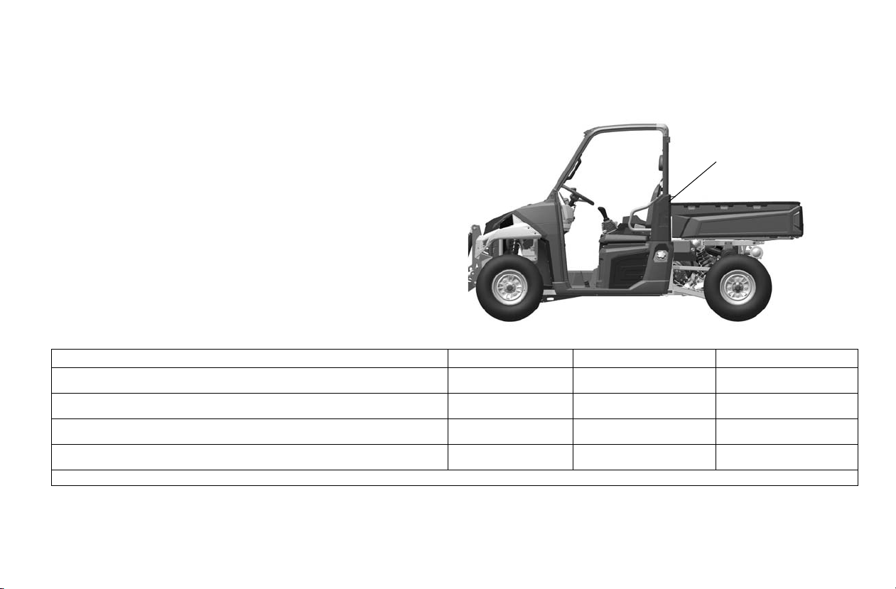
Seat Belts
Riding in this vehicle without wearing the seat belt increases the risk
of serious injury in the event of an accident or sudden stop. Riders
must wear seat belts at all times. Seat belts reduce the severity of
injury in the event of a sudden stop or accident. Always make sure
the seat belts are secured for both the operator and passengers
before riding.
Always follow these guidelines:
Under ANY of these conditions: Do ALL of these steps:
Passenger and/or cargo exceeds half the maximum weight capacity 1. Slow down.
Operating in rough terrain
Operating over obstacles
Climbing an incline
Towing
Operating with attachments installed
Protective Eyewear
Riding in this vehicle without wearing protective eye wear increases
the risk of a serious injuries in the event of an accident.
Operator and all passengers must always wear approved eye
protection (goggles).
Operating With a Load on the Vehicle
The weight of both cargo and passengers impacts vehicle operation.
For your safety and the safety of others, carefully consider how your
vehicle is loaded and how to safely operate the vehicle. Follow the
instructions in this manual for loading, tire pressure, gear selection
and speed.
• Do not exceed vehicle weight capacities. The vehi cle’ s maxim um
weight capacity is listed in the specifications section of this manual
and on a label on the vehicle. When more passenger weight is
added, cargo weight may need to be reduced accordingly.
• The recommended tire pressures are listed in the specifications
section of this manual and on a label on the vehicle.
2. Verify tire pressure.
3. Use extra caution when operating.
14
Page 16

Failure to Inspect Before Operating
Failure to inspect and verify that the vehicle is in safe operating
condition before operating increases the risk of an accident.
Always inspect your BRUTUS before each use to make sure it's in
safe operating condition.
Always follow all inspection and maintenance procedures and
schedules described in the owner's manual.
Exposure to Exhaust
Engine exhaust fumes are poisonous and can cause loss of
consciousness o r death i n a sh ort time . Nev er st art the engin e or let it
run in an enclosed area.
The engine exhaust from this product contains chemicals known to
cause cancer, birth defects or other reproductive harm. Operate this
vehicle only outdoors or in well-ventilated areas.
Operating a Damaged Vehicle
Operating a damaged vehicle can result in an accident. After any
overturn or accident, have a qualified service dealer inspect the entire
machine for possible damage, including (but not limited to) brakes,
throttle and steering systems.
Operating at Excess ive Speeds
Operating this vehicle at excessive speeds increases the operator's
risk of losing control. Alway s operat e at a speed that's appropria te for
the terrain, the visib ility and operating co ndi tio ns, your skills and your
passengers’ skills.
SAFETY
Turning Improperly
Turning improperly could cause loss of traction, loss of control,
accident or overturn. Always follow proper procedures for turning.
Never turn abruptly or at sharp angles. Never turn at high speeds.
Practice turning at slow speeds before attempting to turn at faster
speeds.
Operating on Pavement
This vehicle's tires are designed for off-road use only, not for use on
pavement. Operating this vehicle on paved surfaces (including
sidewalks, paths, parking lots and driveways) may adversely affect
the handling of the vehicle and could result in loss of control and
accident or overturn.
Avoid operating the vehicle on pavement. If it's unavoidable, travel
slowly and avoid sudden turns or stops.
15
Page 17

SAFETY
Operator Safety
Operating on Public Roads
Operating this vehicle on public streets, roads or highways could
result in a collision with another vehicle.
Never operate this vehicle on any public street, road or highway,
including dirt and gravel roa ds . In som e are as it' s unlaw fu l to ope rate
this vehicle on public streets, roads and highways.
Jumps and Stunts
Attempting wheelies, jumps and other stunts increases the risk of an
accident or overturn. Never attempt wheelies, jumps, or other stunts.
Avoid exhibition driving.
Operating in Unfamiliar Terrain
Failure to use extra caution when operating on unfamiliar terrain
could result in an ac ci den t or overturn. Unfamili ar te rrain may contain
hidden rocks, bumps, or holes that could cause loss of control or
overturn.
Travel slowly and use extra caution when operating on unfamiliar
terrain. Always be alert to changing terrain conditions.
Operating on Slippery Terrain
Failure to use extra caution when operating on excessively rough,
slippery or loose terrain could cause loss of traction, loss of control,
accident or overturn.
Do not operate on excessively slippery surfaces.
Always reduce speed and use additional caution when operating on
slippery surfaces.
Improper Hill Climbing
Climbing hills imp roperly can ca use loss of co ntrol or vehicl e overturn.
Always follow proper procedures for clim bin g h ill s as described in the
owner's manual. See page 53.
Stalling While Climbing a Hill
Stalling or rolling backwards while climbing a hill could cause an
overturn. Always maintain a steady speed when climbing a hill.
If all forward speed is lost (engine running):
• Use the travel control pedal to slowly back the vehicle straight
downhill.
• If necessary, apply brake pressure to control speed.
If all forward speed is lost (engine not running):
• Apply the brakes and attempt to restart the engine.
• If engine will not restart, place transmission in neutral and slowly
allow the vehicle to roll straight downhill while applying brake
pressure to control speed.
16
Page 18

Operator Safety
Improper Tire Maintenance
Operating this vehicle with improper tires or with improper or uneven
tire pressure could cause loss of control or accident.
Always use the size and type of tires specified for your vehicle.
Always maintain proper tire pressure as described in the owner's
manual and on safety labels.
Operating on Frozen Bodies of Water
Severe injury or dea th c an re sul t i f th e vehicle and/or the op era tor fall
through the ice. Never operate the vehicle on a frozen body of water
unless you have first v erified that the i ce is suf fi cientl y thi ck t o sup port
the weight and moving force of the vehicle, yo u and your pass engers,
and your cargo, t ogether with any other v ehicl es in your party. Always
check with local authorities and residents to confirm ice conditions
and thickness over your entire route. Vehicle operators assume all
risk associated with ice conditions on frozen bodies of water.
Unauthorized Use of the Vehicle
Leaving the keys in the ignition can lead to unauthorized use of the
vehicle, which cou ld re sult in an accident o r ov ert urn. Always remove
the ignition key when the vehicle is not in use.
Hot Exhaust Systems
Exhaust system components are very hot during and after use of the
vehicle. Hot components can cause burns and fire. Do not touch hot
exhaust system components. Always keep combustible materials
away from the exhaust system. Use caution when traveling through
tall grass, especially dry grass.
SAFETY
Attachment Arm System (If Equipped)
The dealer explains the capabilities and restrictions of the BRUTUS
utility vehicle, attachment and accessories for each application. The
dealer demonstrates the safe operation according to Polaris
instructional materials, which are also available to operators. The
dealer can also identify unsafe modifications or use of unapproved
attachments and accessories. The attachments and buckets are
designed for an attachment arm Rated Capacity. They are designed
for secure fastening to the BRUTUS utility vehicle. The user must
check with the deale r, or POLARIS literature, to determine safe lo ads
of materials of specified densities for the vehicle - attachment
combination.
Safety Rules For Power Take-Off (PTO) Driven
Attachments (If Equipped)
• Keep PTO shields and all guards in place. Replace damaged or
missing shields and guards before operating.
• Follow warnings and instructions on machine signs (decals).
Replace damaged or missing decals.
• Do not wear loose or bulky clothing around the PTO or other
moving parts.
• Keep bystanders away from PTO driven equipment, and never
allow children near machines.
• Read and understand the manuals for the PTO driven equipment
and be aware of safe operating procedures and hazards that may
not be readily apparent.
• Always walk around equipment to avoid coming near a turning
PTO driveline. Stepping over, leaning across or crawling under a
turning PTO driveline can cause entanglement.
• Position the machine and attachment correc tl y to prevent driveline
stress.
• Use caution when raising PTO driven attachment. Excessive
driveline angle can reduce driveline service life.
17
Page 19
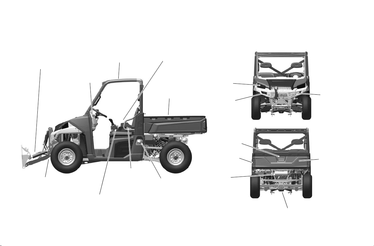
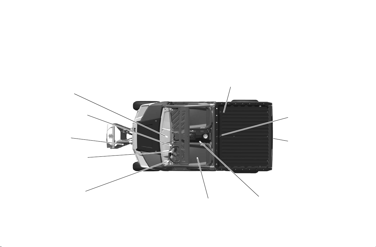
FEATURES AND CONTROLS
Front Bumper/
Brush Guard
Radiator
ROPS / OPS
Cab Frame
Console
Hip Bar
Cargo Box
Fuel Tank Cap
Tailgate Latch
Release
Receiver Hitch
Muffler
(Spark Arrester)
Tailgate
Storage Compartment
Under Seats
Headlights
Center Console
(Model HD and HD
PTO Only)
Attachment Arm
(Model HD and HDPTO Only)
PTO
(Model HDPTO Only)
Taillights
Component Locations
Not all models come with all features. Refer to the specifications section on page 125.
18
Page 20
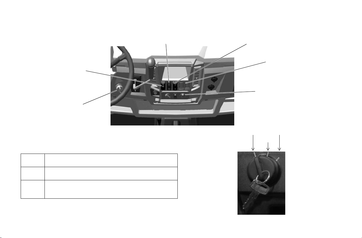
Switches and Indicator Lights
Ignition
Switch
Light Switch
AWD/Differential Switch
Power Lift Assist Switch
(If Equipped)
Blank Switch Op enings -
Available For Accessories
HVAC Switches
(If Equipped)
STARTOFF
ON
Ignition Switch
The ignition switch is a three-position, key-operated switch.
The key can be removed from the switch in the OFF position.
OFF The engine is off. Electrical circuits are off, except Acc,
ON Electrical circuits are on. Electrical equipment can be
START After the wait-to-start indicator turns off, turn the key to
12V.
used.
the START position to engage the electric starter. The
key returns to the ON position when released.
FEATURES AND CONTROLS
19
Page 21
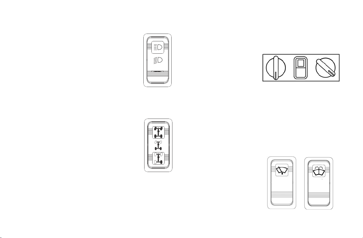
Switches and Indicator Lights
HIGH
OFF
LOW
AWD
Differential Lock
Differential Unlock
Fan
A/C
On-Off
Temp
Control
Wiper
Switch
Washer
Switch
Light Switch
The ignition switch must be in the ON
position to operate the headlights.
Press the top of the rocker switch
toward the dash to place the headlights
on high beam.
Move the rocker switch to the center
position to place the hea dl ights on low
beam.
Press the bottom of the rocker switch
to turn off the headlights.
AWD/Differential Lock Switch
The AWD/Differential
Switch has three positions:
• All Wheel Drive (AWD)
• Differential Lo ck (2WD)
• Differential Unlock
Press the top of the rocker
switch to eng age All Wheel
Drive (AWD). See page 66
for operating instructions.
Move the rocker switch to the center position to lock the differential and operate in rear wheel drive. Press the bottom of
the switch to unlock the differential and allow the two rear
drive wheels to operate independently. See page 66 for differential lock operating instructions.
20
HVAC Switches (If Equipped)
If equipped with a Cab with
HVAC (Heat and Air Conditioning):
• Fan Switch (OFF-LowMed-High)
• Air Conditioning (Press
top of switch to turn Air
Conditioning ON, bottom
for OFF)
• Temperature Control
Switch (Rotate clockwise to increase temperature, counterclockwise to decrease)
Wiper Switch (If Equipped)
If equipped with a cab with a
wiper, the front wiper swit ch
is located on the wiper motor
cover at the top of the front
window:
• Wiper Switch (OFF-LowHigh)
• Washer Switch (Press and
hold top of switch to activate window washer)
Page 22
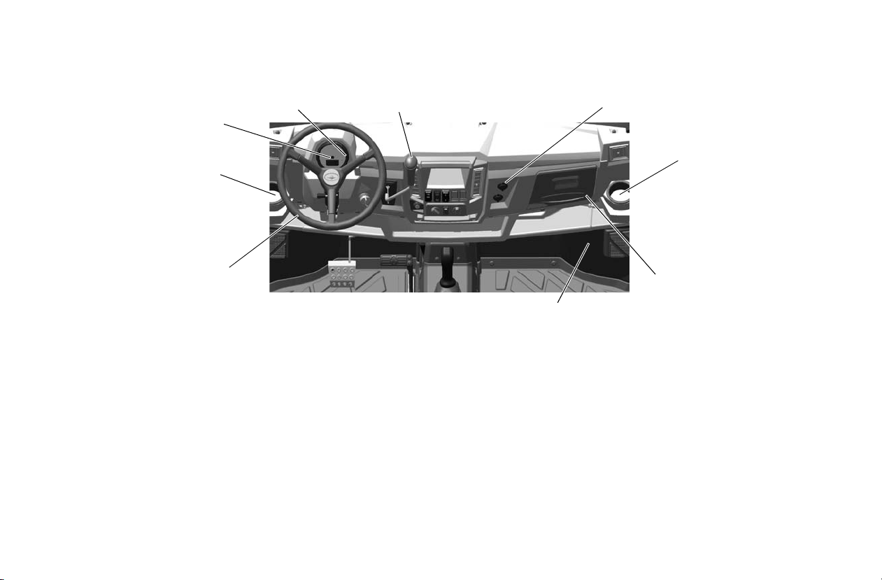
Console
Cup Holder
12V Auxiliary
Outlet
Mode
Button
Storage
Tray
Instrument
Cluster
Gear Selector
(Shifter)
Steering
Wheel
Storage
Compartment
Cup Holder
FEATURES AND CONTROLS
Auxiliary Outlet
The 12-volt receptacles have spade connections on the back
that may be used to power an auxiliary light or other optional
accessories or lights. The connections are behind the console,
under the dash.
Mode Button
The button located on the instrument cluster is used to toggle
through mode options. See pages 27-33.
Gear Selector
Use the gear selector to shift gears. Low gear is the primary
driving range for the BRUTUS. High gear is intended for use
on hard-packed surfaces with light loads. To shift gears, brake
to a complete stop. When the engine is idling, move the lever
to the desired gear.
NOTICE: Shifting gears with the engine speed above idle or while
Tip: Maintaining shift linka ge adjustmen t is important to assure proper
the vehicle is moving could cause transmission damage.
Always shift when the vehicle is stationary and the engine
is at idle.
transmission function. See your dealer if you experience any
shifting prob lems.
21
Page 23
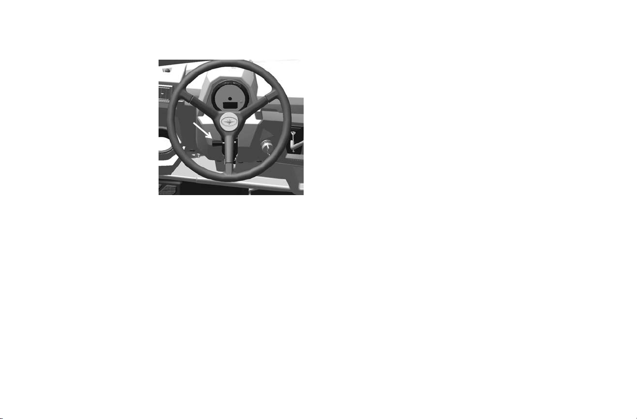
FEATURES AND CONTROLS
Console
Adjustable Steering
Wheel
The steering wheel can be
tilted upward or downward
for rider preference .
Lift and hold th e adjust ment
lever toward you while
moving the steering wheel
upward or downward.
Release the lever when the
steering wheel is at the
desired position.
22
Page 24
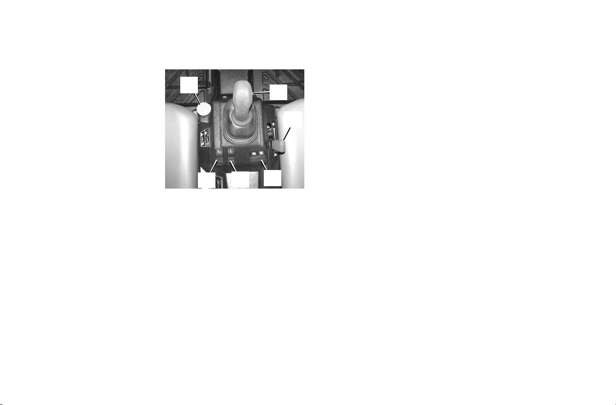
Center Console (For Models HD and
1
2
3
4
5
6
HD
PTO Only)
Joystick - Attachment
Arm
Movement of the joystick
(Item 1) controls the lift and
tilt functions of the attachment arm and the PROTACH attachment system.
See Page 44.
Engine Speed Control
Lever
The engine speed control lever (Item 2)controls engine RPM.
This is used to set engine RPM separately from the travel
speed when using attachments. See Page 47.
Power T ake-Off (PTO)
The front PTO (Item 3) is available on model HDPTO only.
The PTO has a rated speed of 2000 RPM. The PTO is used to
power some attachments. See page 68.
WARNING! Do NOT exceed the rated attachment PTO speed. Stay
clear of rotating driveline. Keep bystanders away. Keep PTO shields
and all guards in place. Disengage PTO, put the gear selector in
PARK, stop the engine and make sure all rotating components are
stopped before exiting utility vehicle. Do NOT service the utility
vehicle or attachment with the PTO engaged. Do NOT service the
attachment in a raised position unless properly blocked and with all
rotating components stopped. Disengage PTO for road travel.
FEATURES AND CONTROLS
Joystick Lock Switch
The joystick lockout switch (Item 4) is used to active or lockout the joystick functions. The joystick should be lockout
when no attachments are instal led. This will keep the joystick
from accidentally being activated. See Page 44.
Tilt Lock Switch
The tilt lockout switch (Item 5) locks out the tilt function. See
Page 44.
Tip: When operating PTO driven attachments, the tilt lockout switch
will automatically activate. Using the attachment with the tilt
locked out will limit the possibility of tilting the attachment while
the PTO shaft is turning and putting stress on the PTO driveline
u-joints. Before engaging the PTO system, tilt the attachment to
the desired operating position. See your attachment Owner’s
Manual for detailed information.
Front Auxiliary Hydraulic Switch
The front auxiliary hydraulic switch (Item 6) controls hydraulic flow to the front male and female coupler for attachment
operation. See Page 45.
23
Page 25
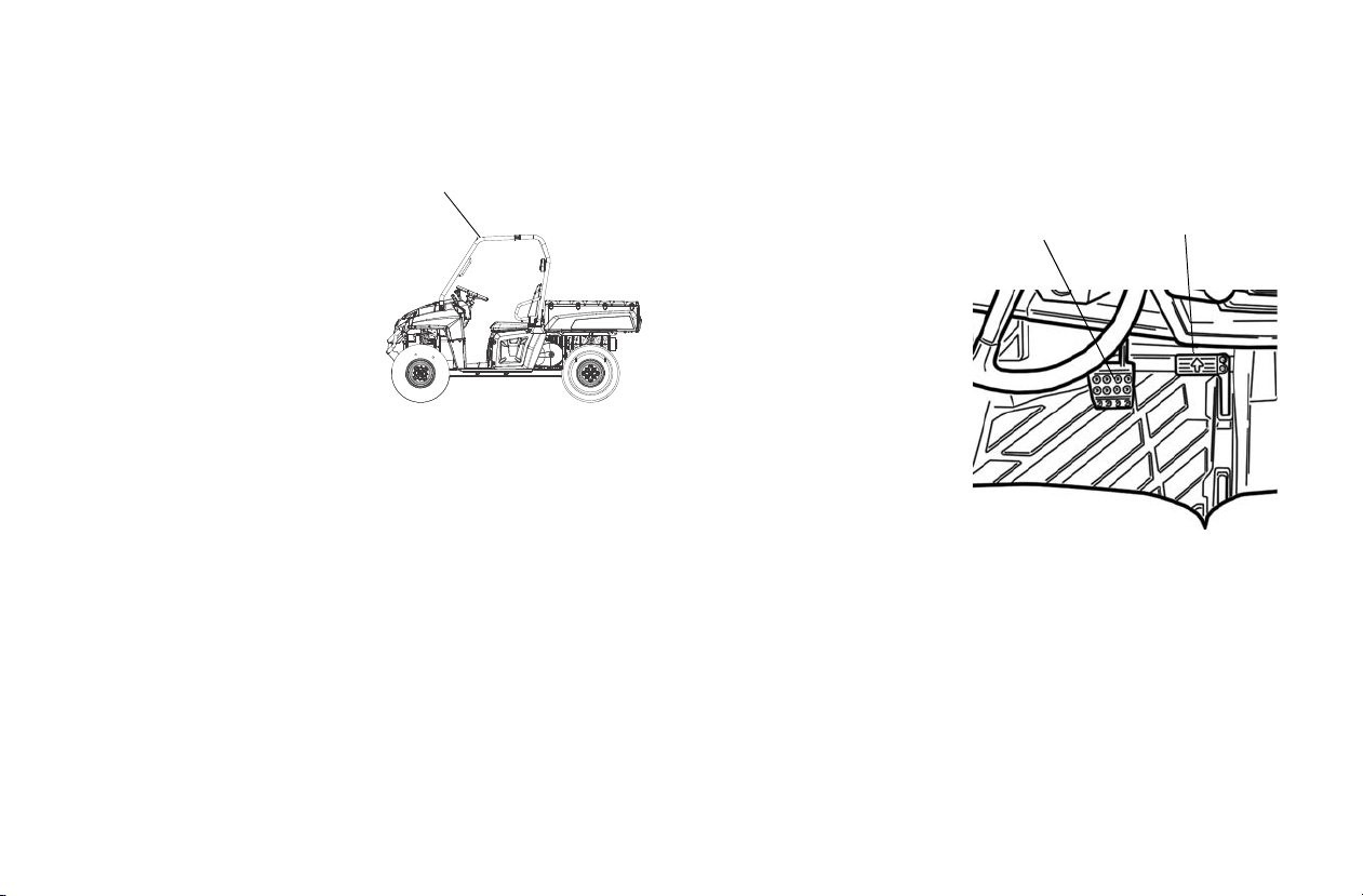
FEATURES AND CONTROLS
ROPS / OPS
Travel Control
Pedal
Brake
Pedal
Rollover Protective Structure (ROPS) /
Occupant Protective Structure (OPS)
The Rollover Protective Structure (ROPS) on this vehicle
meets OSHA 1928.53 rollover
performance requirements. The
Occupant Protective S t ruc tur e
(OPS) on this vehicle meets
ANSI/OPEI B71.9-2012 occupant requirements. Always have
your authorized POLARIS
dealer thoroughly inspect the
ROPS / OPS if it ever becomes
damaged in any way.
No device can assure occupant protection in the event of a
rollover . Always follow all safe operating practi ces out li ned in
this manual to avoid vehicle rollover.
WARNING! Vehicle rollover could cause severe injury or death.
Always avoid operating in a manner that could result in vehicle
rollover.
Storage Compartments
A storage compartment is located under both the driver’s and
operator’s seat.
Trailer Hitch Bracket
This vehicle is equipped with a receiver hitch bracket for a
trailer hitch. To avoid injury and property damage, always
heed the warnings and towing capacities outlined on pages 61.
Brake Pedal
Depress the brake pedal to
slow or stop the vehicle.
Apply the brakes while
starting the engine.
Travel Control
Pedal
The travel control pedal is
used to control the forward
and backward movement of
the utility vehicle. The farther the pedal is pressed, the
faster the travel speed.
Press the toe of the pedal for
forward travel, press the heel of the pedal for backward travel.
24
Page 26
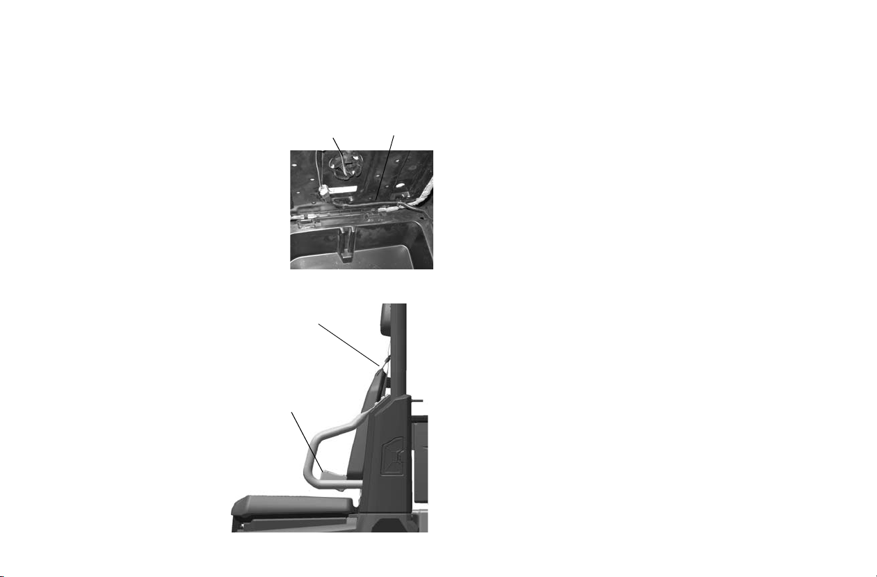
Seat Removal
Seat
Switch
Harness
Model HD
PTO Only
Buckle
Latch Plate
Pull up on the rear of the seat and tilt it
toward the front of the vehicle. In stall
the seat by sliding the tabs into the
front of the seat base. Push down
firmly on the rear of the seat until the
pins are full y s eat ed into the gro mmets .
Tip: For Model HDPTO; a seat switch is
located under the operator’s seat. Set
the seat aside if possible to avoid disconnecting the seat switch. If the seat
switch is disconnected, the harness
must be secured in it’ s origin al positio n
to avoid harness damage.
Seat Belt s
This POLARIS vehicle is
equipped with three-point
lap and diagonal seat belts
on all external seats.The
center seat is equipped
with a lap-style seat belt.
Always make sure the se at
belts are secured for all
riders befo re operating.
WARNING! Falling from a
moving vehicle c ould resu lt in
serious injury or death.
Always fasten your seat belt
securely before operating or
riding in the BRUTUS.
FEATURES AND CONTROLS
To wear the seat belt properly, follow this procedure:
1. For 3-point belts, pull the seat belt latch downward and
across your chest toward the buckle at the inner edge of
the seat. The belt should fit snugly across your hips and
diagonally across your chest. Make sure the belt is not
twisted. For lap style belts, place the belt across your lap
as low on your hips as possible. Make sure that the belt is
not twisted.
2. Push the latch plate into the buckle until it clicks.
3. Release the strap, it will self-tighten.
Tip: The center belt must be tightened manually by pulling on the
strap.
4. To release the seat belt, press the square red button in the
buckle's center.
25
Page 27

FEATURES AND CONTROLS
Seat Belt s
Seat Belt Inspection
Inspect all seat belts for proper operation before each use of
the vehicle.
1. Push the latch plate into the buckle until it clicks. The
latch plate must slide smoothly into the buckle. A click
indicates that it's securely latched.
2. Push the red release latch in the middle of the buckle to
make sure it releases freely.
3. Pull each seat belt completely out and inspect the full
length for any damage, including cuts, wear, fraying or
stiffness. If any damage is found, or if the seat belt does
not operate properly, have the seat belt system checked
and/or replaced by an authorized POLARIS dealer.
4. To clean dirt or debris from the seat belts, sponge the
straps with mild soa p and wate r. Do not use bleach, dye or
household detergents.
26
Page 28
1
20
10
11
12
13
14
15
16
17
18
19
2
3
3
4
5
6
7
8
9
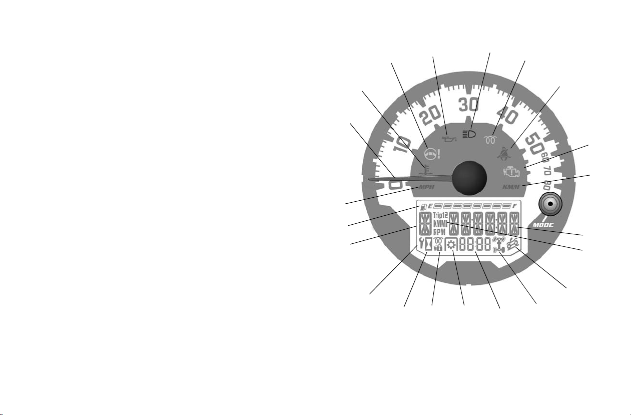
Instrument Cluster
Your vehicle is equipped with an instr ument clus ter that senses
vehicle speed from the transmission. In addition to showing
vehicle speed, the s peedometer needle fl as hes when a warning
condition exists.
NOTICE: High water pressure may damage components. Wash the
Rider Information Center
vehicle by hand or with a garden hose using mild soap.
Certain products, including insect repellents and
chemicals, will damage the instrument cluster lens and
other plastic surfaces. Do not use alcohol to clean the
instrument cluster. Do not allow insect sprays to contact
the lens. Immediately clean off any fuel that splashes on
the instrument cluster.
The rider information display is located in the instrument cluster. All segments will light up for 1 second at start-up. If the
instrument cluster fails to illuminate, a battery over-voltage
may have occurred and the instrument cluster may have shut
off to protect the electronic speedometer. If this occurs, take
the vehicle to your Polaris dealer for proper diagnosis.
1. Vehicle Speed Display - Analog display of vehicle speed
in MPH or km/h.
2. Information Display Area - Odometer / Tri p Meter /
Tachometer / Engine Temperature / Engine Hours /
Service Info - LCD display of the service hour interval,
total vehicle miles or km., total engine hours, a trip meter,
engine RPM and engine temperature.
FEATURES AND CONTROLS
27
Page 29

FEATURES AND CONTROLS
Instrument Cluster
3. MPH / KM/H Display - MPH is displayed when the
instrument cluster is in the Standard mode. KM/H is dis-
played when the instrument cluster is in the Metric mode.
4. High Beam Indicator - LED icon illuminates whenever
the Headlam p switch is in the high beam position.
5. Fuel Level Indicator - LCD bar graph indicating current
fuel level. All segments will flash when the last segment is
cleared indicating a low fuel warning.
6. Clock / PTO RPM - Displays current time in either 12hour or 24-hour formats. When the PTO is engaged, PTO
RPM will be indicated instead of the clock.
7. Engine / Hydraulic Fluid Temperature Indicator - LED
icon illuminates when the ECM determines the engine is
overheating. The indicators will initially flash to indicate
the engine is overheating. The indicators will stay lit and
not flash if a severe overheating condition exists.
8. PTO Indicator - PTO is engaged when this is illuminated.
PTO RPM will be displayed in the Clock field (6) ONLY
when engine RPM is displayed in the Information Display
Area (2).
9. Check Engine MIL - Illuminated when the ECM has
detected a Diagnostic Trouble Code in the engine management system.
10. Unit Lock - N/A on this model.
11. Hour Meter - Illuminates when the dis play (2) i s showing
hours.
12. Low Oil Pressure Indicator - LED icon illuminates low
engine oil or hydraulic fluid pressure is sensed.
13. Gear Position Indicator - Displays gear selector position.
H = High
L = Low
N = Neutral
P = Park
-- = Gear Signal Error (shifter stuck between gears)
14. Power Steering System MIL - N/A on this model.
15. Glow Plug Indicator - Illuminated when the glow plugs
are active. Light goes out when the engine is ready to start.
16. Seat Belt Indicator - LED ic on illuminate s for 10 secon ds
when the key is turned to the ON position. The lamp is a
reminder to the operator to ensure all riders are wearing
seat belts before operating the vehicle.
17. AWD/TURF Indicator - Illuminate to ind icate how many
drive wheels are active. This will tell you if you are in
AWD, 2WD, or Turf.
18. ADC Indicator - N/A on this model.
19. Service Interval Indicato r - Preset at the factory and
adjustable by the user, a flashing wrench symbol alerts the
operator that the preset service interval has been reached
and maintenance should be performed. The wrench icon
will flash for 10 seconds upon start-up once it reaches 0.
20. Unit of Measurement - Indicates the measurement (Trip
1, Trip 2, KM, MI, RPM) being displayed in the Informa-
tion Display Area (2).
28
Page 30
Instrument Cluster
Information Display Area
The LCD portion of the instrument cluster is the information
display area which displ ays the f ollowi ng infor mat ion: odometer, trip meter, RPM, battery voltage, engine temperature, air
temperature, engine hours , tro ubl e code s, service interval, and
clock.
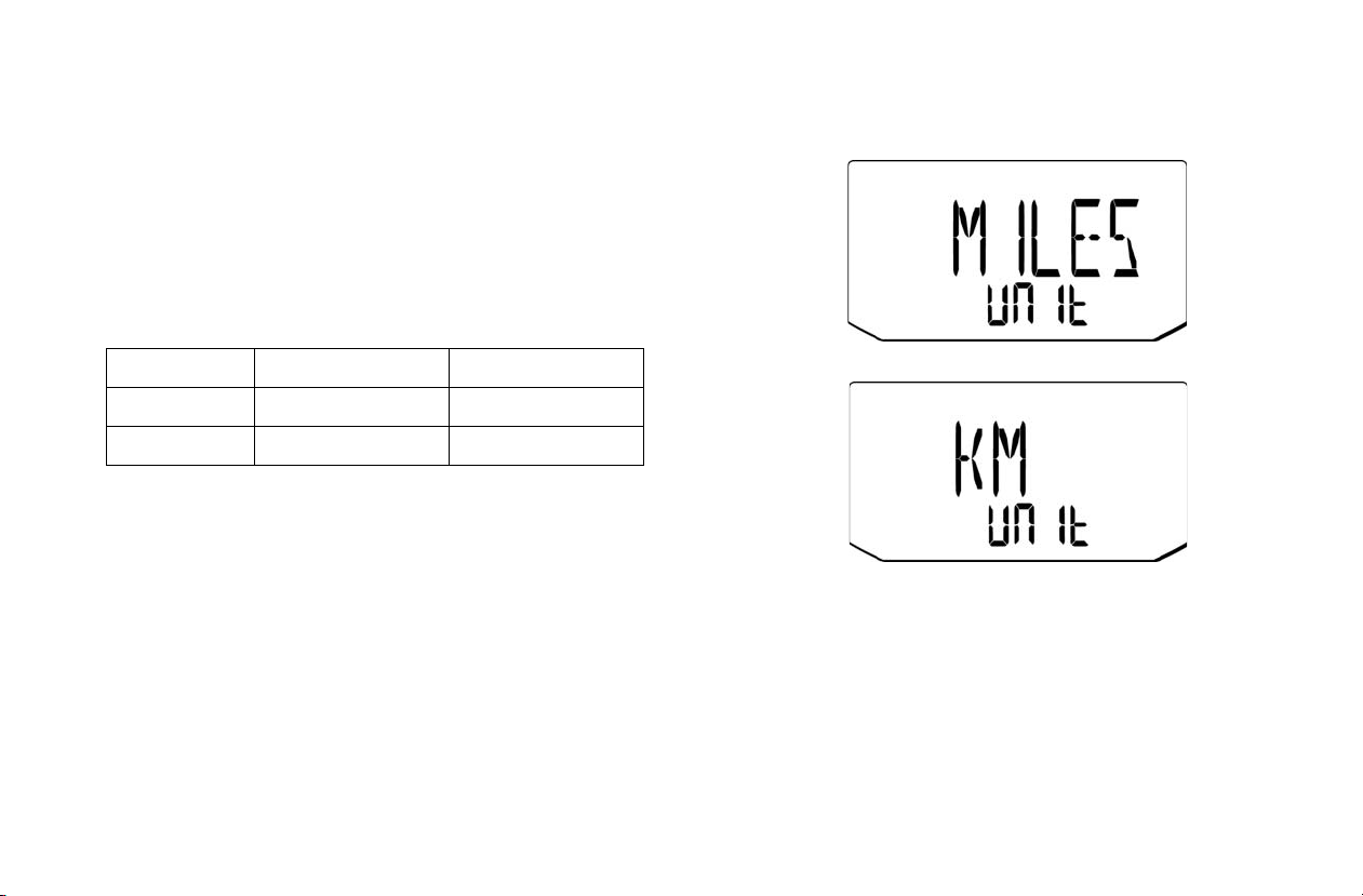
Units of Measurement
Distance Miles (MPH) Kilometers (KM/H)
Temperature Fahrenheit Celsius
Time 12-Hour Clock 24-Hour Clock
T o change bet ween S tandard and Metri c units of mea surement,
follow these steps:
1. Turn the key to the OFF position.
2. Press and hold the MODE button while turning the key to
the ON position.
3. When the display flashes the distance setting, tap the
MODE button to advance to the desired setting.
FEATURES AND CONTROLS
4. Press and hold the MODE button to save the setting and
advance to the next display option.
5. Repeat the procedure to change rema ining displ ay setting s.
29
Page 31

FEATURES AND CONTROLS
Instrument Cluster
Odometer
Engine Hours
The odometer records and displays the total distance traveled
by the vehicle. The odometer can not be reset.
Trip Meter
The trip meter records the miles tr aveled by the vehicle on
each trip. To reset the t rip meter:
1. Toggle the MODE button to TRIP 1.
2. To reset to 0, push and hold the MODE button until the
distance display changes to 0.
30
Engine hours are logged anytime the engine is running. Total
hours can not be reset.
Tachometer (RPM)
Engine RPM can be displayed digitally.
PTO RPM, when engaged, is indicated after the PTO icon.
Page 32
Instrument Cluster
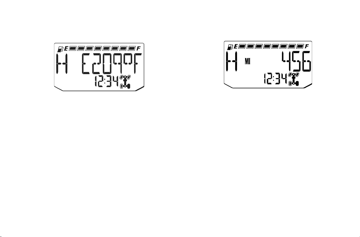
Engine Temperature
FEATURES AND CONTROLS
Clock
Engine temperature can be displayed in F° or ° C. Refer to
“Units of Measurement” to change the format.
The clock displays the time in a 12-hour or 24-hour format.
Refer to “Units of Measurement” to change the format (Standard 12-hour / Metric-24 hour). To set the clock, follow these
steps:
1. Toggle the MODE button until the odometer is displayed.
2. Press and hold the MODE button until the hour segment
flashes. Release the button.
3. With the segment flashing, tap the MODE button to
advance to the desired setting.
4. Press and hold the MODE button until the next segment
flashes. Release the button.
5. Repeat steps 3-4 twice to set the 10 minute and 1 minute
segments. After completing the 1-minute segment, step 4
will save the new settings and exit the clock mode.
31
Page 33
FEATURES AND CONTROLS
Instrument Cluster
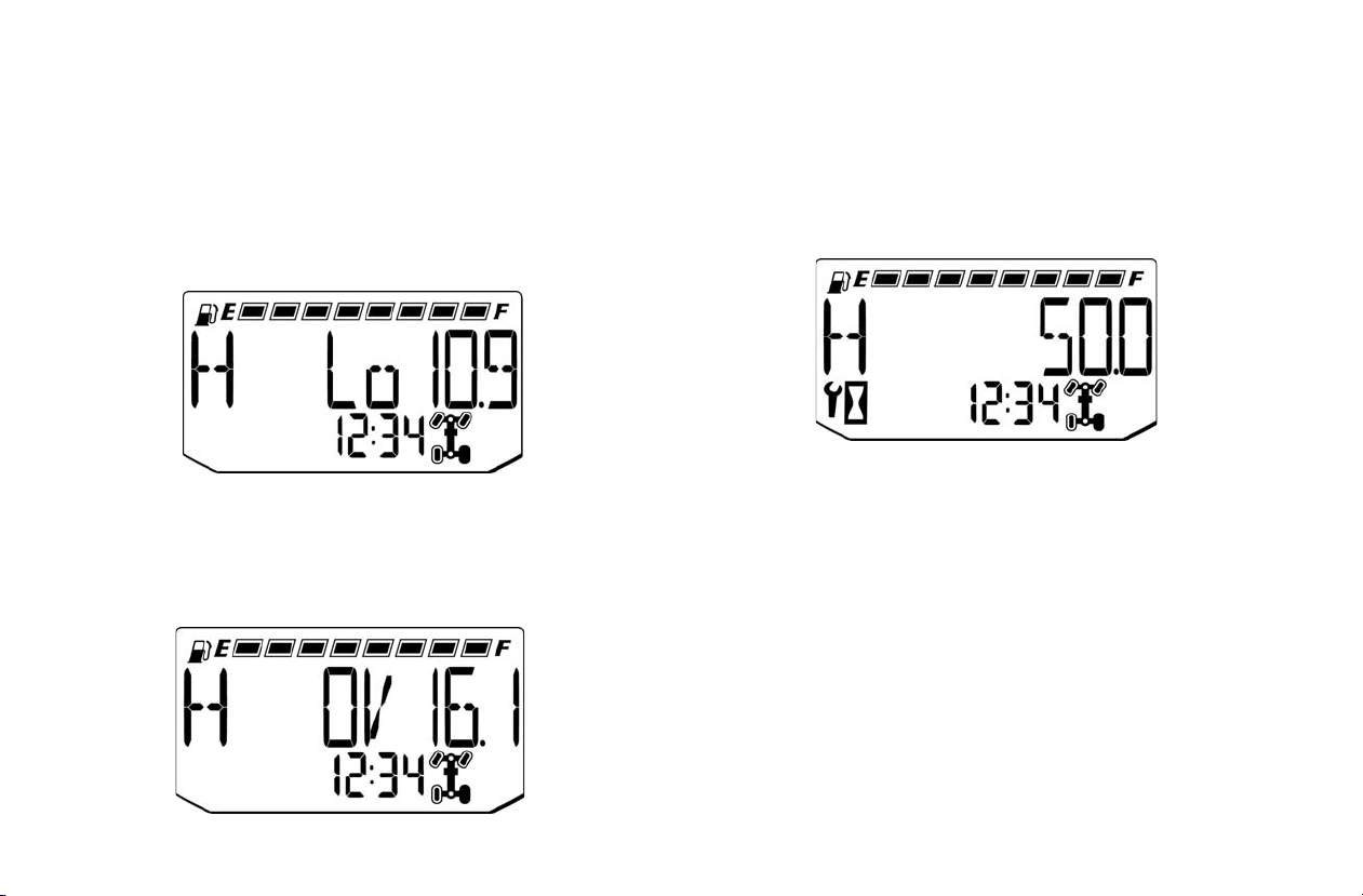
Battery Under / Over Voltage
This warning usually indicates that the vehicle is operating at
an RPM too low to keep the battery charged. It may also occur
when the engine is at idle and a high electrical load is applied
(lights, cooling fan or other accessories).
Battery Voltage Low
If battery voltage drops below 11 volts, a warning screen will
display “Lo” and provide the present battery voltage. If voltage drops below 8.5 volts, LCD backlighting and icons will
turn off.
Battery Voltage High
If battery voltage rises above 15 volts, a warning screen will
display “OV” and provide the present battery voltage. If voltage rises above 16.5 volts, LCD backlighting and icons will
turn off.
Programmed Service Interval
The initial factory service interval setting is 50 hours. Each
time the engine is start ed, the engine hours are sub tracted from
the service interva l hours. When the ser vice inter val reaches 0,
the LCD wrench icon will flash for approximately 10 seconds
each time the engine is started.
To change the hour setting or reset the function, follow these
steps:
1. Toggle the MODE button until the wrench icon is displayed in the information area.
2. Press and hold the MODE button unti l the i nformat ion dis play area begins to flash.
3. Toggle the MODE button to increase the service interval
hours in 5 hour increments to a maximum of 100 hours.
4. To turn off the service interval function, toggle the MODE
button until “OFF” is displayed.
32
Page 34
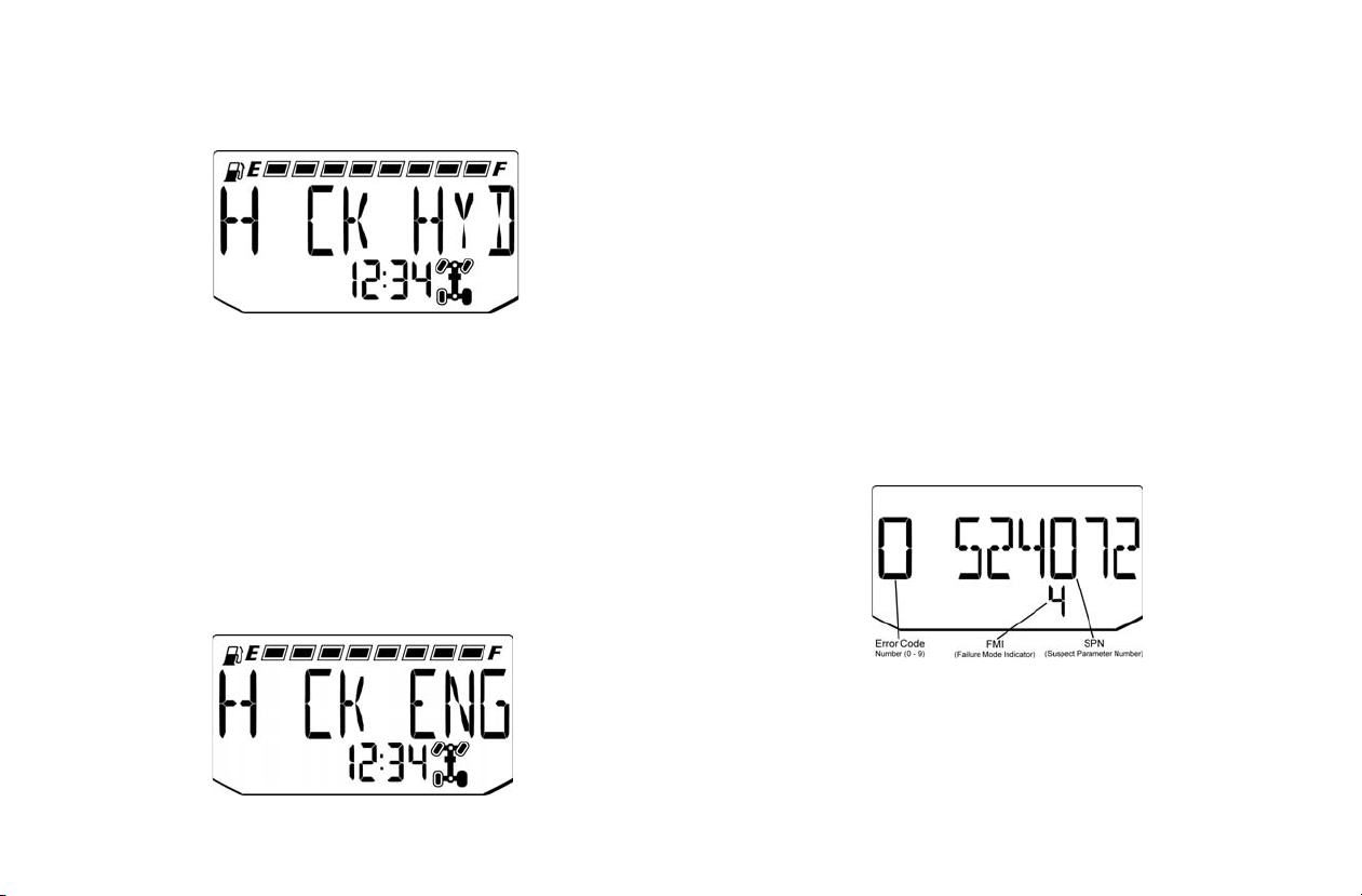
Instrument Cluster
Check Hydraulic
Indicates too low of hydraulic oil pressure which is likely
caused by a plugged or too high of hydraulic oil temperature.
The Oil or Temperature l ight will illuminate along with this
message.
Check Engine / Trouble Code Display
The diagnostic mode i s acces sible only when the che ck engi ne
MIL has been activated
Use the following procedure to display diagnostic trouble
codes that were acti vated durin g curr en t ign ition cycl e caus ing
the MIL to illuminate. Diagnostic trouble codes will remain
stored in the gauge (even if MIL turns off) until the key is
turned off.
FEATURES AND CONTROLS
1. If the trouble codes are not displayed, use the MODE button to toggle until “CK ENG” displays on the information
display area.
2. Press and hold the MODE button to enter the diagnostics
code menu.
3. A set of three numbers will appear in the information area.
4. The first number (located far left) can range from 0 to 9.
This number represents the total number of trouble codes
present (example: 2 means there are 3 codes present).
5. The second number (located top right) can be 2 to 6 digits
in length. This number equates to the suspected area of
fault (SPN).
6. The third number (located bottom right) can be 1 to 2 digits in length. This number equates to t he f au lt mode (FMI).
7. See your dealer for Diagnostic Trouble Codes.
8. If more than one code exists, press the MODE button to
advance to the next trouble code.
9. To exit the diagnostic mode, press and hold the MODE
button or turn the ignition key OFF once the codes are
recorded.
33
Page 35

OPERATION
WARNING
Failure to operate the v ehi cl e properly can resul t in a collision , lo ss o f
control, accident or overturn, which may result in serious injury or
death. Read and understand all safety warnings outlined in this
owner’s manual.
Break-In Period
The break-in period for your new vehicle is the first 50 hours
of operation. No single a ct ion on your part is as impor ta nt as a
proper break-in per iod . Car ef ul treatment of a new e ngi ne wi ll
result in more efficient performance and longer life for the
engine.
New Engine Break-In
1. Fill the fuel tank with the recommended fuel. See page 36.
2. On the in itial engine start-up, allow the engine to idle for
approximately 15 minutes. Check for proper engine oil
pressure, diesel fuel leaks, engine oil leaks, coolant leaks,
hydraulic leaks and proper operation of the indicators and
gauges.
3. During the first hour of operation, vary engine speed and
the load on the engine. Short periods of maximum engine
speed and load are de sirable. Avoid prolonged operatio n at
minimum or maximum engine speeds and loads for the
next 4 to 5 hours.
4. During the break-in period, carefully observe the engine
oil pressure, engine temperature and hydraulic fluid temperature.
5. Check the engine oil, engine coolant and hydraulic fluid
level frequently during the break-in period. Perform regular checks on areas outlined on the daily pre-ride inspection checklist. See page 35.
6. Change both the engine oil and the filter at 50 hours.
7. Check fluid levels of transmission and all gearcases after
the first 25 hours of operation and every 100 hours thereafter.
34
Page 36

OPERATION
Pre-Ride Inspection
Failure to inspect and verify that the vehicle is in safe operating condition before operating increases the risk of an accident.
Always inspect the vehicle before each use to make sure it's in safe operating condition.
Item Remarks Page
Brake system/pedal travel Ensure proper operation. 24, 101
Brake fluid Ensure proper level. 101
Front and Rear suspension Inspect, lubricate if necessary. 119
Seat Belts Check length of belt for damage, check latches for proper operation. 26
ROPS/OPS Check condition of ROPS/OPS and mounting hardware. 26
Steering Ensure free operation. 103
Tires/wheels/fasteners Inspect condition and pressure. Inspect, ensure fastener tightness. 112
Safety Signs (Decals) Check for damaged or missing signs (decals). Replace any signs that are damaged or missing.
Frame nuts, bolts, fasteners Inspect, ensure tightness. Fuel and oil Ensure proper levels. 39, 88
Coolant level Ensure proper level. 92
Coolant hoses Inspect for leaks. Travel Control Pedal Ensure proper operation. 24
Indicator lights/switches Ensure operation. 19
Air filter, pre-filter Inspect, clean and replace as needed. 95
PTO (If Equipped) Inspect splines, guards, shields and hardware, ensure tightness, replace damaged parts. 51
Brake light/tail lamp /Headlamp Check operation, apply POLARIS dielectric grease when lamp is replaced. 102, 114
Heater/Air Conditioning Filter Clean and replace filter as needed during heating and cooling season. 106
35
Page 37

OPERATION
Fuel Recommendations
NOTICE: For the best engine performance, to prevent engine
POLARIS recommends the follow ing diesel fuels for use in
this vehicl e:
•Low Sulfur
• Ultra Low Sulfur #2
• #1 Diesel Fuel containing no more than 5% bio-diesel (see
page 37)
See page 39 for cold we ather fu el blend recommendati ons. For
more information about recommended diesel fuels and the
consequences of using bio-diesel fuel exceeding 5% bio-diesel, see Additional Technical Fuel Requirements below.
Diesel fuel should comply with the following world-wide
specifications.
Diesel Fuel Specification Location
ASTM D975
No. 1D S15, S500
No. 2D S15, S500
EN590:96 European Union
ISO 8217 DMX International
BS 2869-A1 or A2 United Kingdom
JIS K2204 Grade No. 2 Japan
KSM-2610 Korea
GB252 China
damage and to comply with EPA/CARB warranty
requirements, use ONLY the recommended diesel fuels.
Use only CLEAN diesel fuel.
USA
Additional Technica l Fuel Requirements
• The fuel cetane number should be equal to 45 or higher.
• The sulfur content must not exceed 0.5% by volume. Less
than 0.5% is preferred. Espe cially in th e U.S.A. and Canada,
Low Sulfur (300 to 500 ppm (mg/kg) or Ultra Low Sulfur
fuel should be used.
• Bio-Diesel fuels: see pages 37-38.
• NEVER mix ker osene, used engin e oil or residual fuels with
diesel fuel.
• Water and sediment in the fuel should not exceed 0.05% by
volume.
• Keep the fuel tank and fuel-handling equipment clean at all
times.
• Poor quality fuel can reduce engine performance and/or
cause engine damage.
• Fuel additives are not recommended. Some fuel additives
may cause poor engine performance.
• Ash content must not exceed 0.01% by volume.
• Carbon residue content must not exceed 0.35% by volume.
Less than 0.1% is preferred.
• Total aromatics content should not exceed 35% by volume.
Less than 30% is preferred.
• PAH (polycyclic aromatic hydrocarbons) content should be
below 10% by volume.
• Metal content of Na, Mg, Si and Al should be equal to or
lower than 1 mass ppm (test analysis method JPI-5S-44-95) .
• Lubricity: Wear mark of WS1.4 should be Max. 0.018 in.
(460µm) at HFRR test.
36
Page 38

Fuel Recommendations
Bio-Diesel Fuels
In Europe and in the United States, as well as some other countries, non-mineral oil based fuel resources such as RME
(Rapeseed Methyl Ester) and SOME (Soybean Methyl Ester),
collectively known as FAME (Fatty Acid Methyl Esters), are
being used as extenders for mineral oil derived diesel fuels.
YANMAR approves the use of bio-diesel fuels that do not
exceed a blend of 5% (by vol ume) of FAME with 95% (by volume) of approved mineral oil deriv ed die sel fu el. Suc h bio- diesel fuels are known in the marketplace as B5 diesel fuels.
These B5 diesel fuels must meet certain requirements:
1. The bio-fuels must meet the minimum specifications for
the country in which they are used.
• In Europe, bio-diesel fuels must comply with the European
Standard EN14214.
• In the United States, bio-diesel fuels must comply with the
American Standard ASTMD-6751.2.
2. Bio-fuels should be purchased only from recognized and
authorized diesel fuel suppliers.
OPERATION
Precautions and concerns regarding the use of bio-fuels:
1. Free methanol in FAME may result in corrosion of aluminum and zinc FIE components.
2. Free water in FAME may result in plugging of fuel filters
and increased bacterial growth.
3. High viscosity at low temperatures may result in fuel
delivery problems, injection pump seizures and poor
injection nozzle spray atomi za ti on.
4. FAME may have adverse effects on some elastomers (s eal
materials) and may result in fuel leakage and dilution of
the engine lubricating oil.
5. Even bio-diesel fuels that comply with a suitable standard
as delivered will require additional care and attention to
maintain the quality of the fuel in the equipment or other
fuel tanks. It is important to maintain a supply of clean,
fresh fuel. Regular flushing of the fuel system and/or fuel
storage containers may be necessary.
6. The use of bio-diesel fuels that do not comply with the
standards as agreed to by the diesel engine manuf acturers
and the diesel fuel injection equipment manufacturers, or
bio-diesel fuels that have degraded as per the precautions
and concerns above, may affect the warranty coverage of
your engine.
37
Page 39

OPERATION
Fuel Recommendations
Bio-Diesel Fuels
B6 To B20 Bio-diesel Fuel Blend Usages
B6 to B20 bio-diesel is not approved for this POLARIS application.
Approved Engines
Only the YANMAR TNM engine series listed below may
operate with bio-diesel fuel concentrations up to B5 for
POLARIS applications
NOTICE: Do not exceed bio-diesel fuel ble nd B5 for thi s POLARIS
application.
•3TNM72
Approved Fuel
NOTICE: Raw pressed vegeta ble oils are no t con si dere d bi o-di es el,
and are unacceptable for use as fuel in any concentration
in YANMAR engines.
Bio-diese l fuel blends up to B5 must comply with the following standards:
• EN14214 (European standard) and/or ASTM D-6751
(American standard).
• All applicable engines may operate with bio-diesel fuel up
to a maximum B5 (5% bio-diesel blend) concentration.
Operating Conditions with B5 Bio-diesel Fuel Blends
Engine Warranty
Damages, performance or service concerns determined to be
caused by the use of bio-diesel fuel not meeting the specifications outlined above are not considered to be defects in material or factory workmanship and are not covered under
warranty. The same applies to damages or other concerns
induced by not complying with the recommended operating
conditions of YANMAR engines with bio-diesel fuel.
Handling Fuel
WARNING! Diesel fuel is flammable and explosive under certain
conditions.
• NEVER refuel with the engine running.
• Always refuel outdoors or in a well ventilated area.
• Fill the fuel tank with diesel fuel ONLY. Filling the fuel tank with
gasoline may result in a fire and will damage the engine.
• Remove flammable material containers from the box before filling
them with fuel.
• Do not smoke or allow open flames or sparks in or near the area
where refueling is performed or where fuel is stored.
• Wipe up all spills immediately.
• Keep sparks, open flames or any other form of ignition (match,
cigarette, static electricity source) well away when refueling.
• NEVER remove the fuel cap while the engine is running.
• NEVER overfill the fuel tank. Do not fill the tank neck.
• If fuel spills on your skin or clothing, immediately wash it off with
soap and water and change clothing.
38
Page 40

Fuel Recommendations
Refueling
The fuel tank filler cap is located on
the outside left side of the vehicle
near the operator seat. Remove the
cap and add the recommended fuel
to the bottom of the filler neck. Do
not overfill.
Cold Weather Operation
Cold weather operation can result in fuel gelling if the incorrect fuel type is used. Use the following fuel blending guideline to prev ent this from occurring.
Fuel Blending Guideline
Temperature No. 2 No. 1
+15° F (9° C) 100% 0%
Down to -20° F (-29° C) 50% 50%
Below -20° F (-29° C) 0% 100%
Block Heater Use
If this vehicle will be operated when temperatures are in the
+5° to -25° F. (-15° to -32° C) range, a block heater must be
installed. Please see your dealer to purchase a block heater kit.
OPERATION
Bio-Diesel Blended Fuel
NOTICE: Never use bio-diesel blended fuel containing more than
5% bio-diesel in this vehicle. See page 37.
Bio-diesel blended fuel has unique qualities that should be
considered before using it in this vehicle:
• Cold weather conditions can lead to plugged fuel system
components and hard starting.
• Bio-diesel blended fuel is an excellent medium for micro-
bial growth and contamination which can cause corrosion
and plugging of fuel system components.
• Use of bio-diesel blended fuel may result in premature fail-
ure of fuel system components, such as plugged fuel filters
and deteriorated fuel lines.
• Shorter maintenance intervals may be required, such as
cleaning the fuel system and replacing fuel filters and fuel
lines.
• Using bio-diesel blended fuels containing more than five
percent (5%) bio-diesel can affect engine life and cause
deterioration of hoses, tubes, injectors, injector pump and
seals.
39
Page 41

OPERATION
Cold Weather Operation
Bio-Diesel Blended Fuel
Use the following guidelines if bio-diesel blended fuel is used:
• Never use bio-diesel blended fuel containing more than 5%
bio-diesel in this vehicle.
• Ensure the fuel tank is as full as possible at all times to prevent moisture from collecting in the fuel tank.
• Ensure that the fuel tank cap is securely tightened.
• Clean up any spilled fuel immediately to prevent damage to
painted surfaces.
• Drain all water from the fuel filter daily before operating the
vehicle.
• Do not exceed the engine oil change interval. Extended
intervals can result in engine damage.
• Before vehicle storage, drain the fuel tank, refill with 100%
petroleum diesel fuel, add fuel stabilizer and run the engine
for at least 30 minutes.
NOTICE: Bio-diesel blended fuel does not have long term stability
and should not be stored for more than three months.
Operating Conditions
NOTICE: Observe the following environmental operating conditions
to maintain engine performance and avoid premature
engine wear.
• Avoid operating in the presence of chemical gases or fumes.
• Avoid operating in a corr osive atmosphe re such as s alt water
spray.
• NEVER operate the engine in a floodplain unless proper
precautions are taken to avoid being subject to a flood.
• NEVER expose the engine to the rain.
• The standard range of ambient temperatures for the normal
operation of YANMAR engines is from +5° F (-15° C) to
+104° F (+40° C).
• If the ambient temperature exceeds +104° F (+40° C), the
engine may overheat and cause the engine oil to break
down.
• If the ambient temperature is between +5° F (-15° C) and 25° F (-32° C), POLARIS recommends the use of a block
heater. See page 39.
40
Page 42

Starting the Engine
START
HELP
NOTICE: NEVER use an engine
Before operating this vehicle in
cold weather, review the cold
weather operation infor mat ion
beginning on page 39.
Always wait for the glow pl ug indi cator light to turn off before cranking the engine.
Tip: Engine will not start unless: Gear selector is in Park or Neutral,
1. Always start the engine outdoors or in a well-ventilated
2. Sit in the driver's seat and fasten the seat belt.
3. Apply the brakes.
4. Put the gear selector lever in the Park position.
5. Turn the ignition switch to the ON position and wait for
6. Turn the ignition switch past the ON position to START.
7. If the engine does not start withi n five second s, rele as e the
starting aid such as ether.
Engine damage will result.
travel control pedal is in neutral and PTO (if equipped) is OFF.
area.
the glow plug indicator light to turn off before cranking
the engine.
Engage the starter f or a maximum of fi ve seconds. Rel ease
the key when the engine starts.
ignition switch and wai t five second s. Repeat steps 5 an d 6
until the engine starts.
OPERATION
8. Allow the engine to warm to operating temperature. (For
Models HD and HD
with the engine speed control lever to aid in warm up unt il
the engine idles smoothly.)
NOTICE: Operating the vehicle immediately after starting could
cause engine and hydraulic compo nent damage . Allow the
engine to warm up for several minutes before operating
the vehicle.
Stopping the Engine
For maximum engine life, allow the engine to idle, without
load, for 5 minutes. This will allow the engine components
that operate at high temperatures, such as the exhaust system,
to cool slightly before the engine is shut down.
1. Press the brake pedal until the utility vehicle comes to a
complete stop.
2. For models HD and HD
arm and put the attachment flat on the ground.
3. Move the gear selector lever to Park.
4. For models HD and HD
control lev er to low idle. Disengage the PTO and make
sure all rotating components are completely stopped.
5. Turn the engine off and remove the key to prevent unau-
thorized use.
WARNING! A rolling vehicle can cause serious injury. Always place
the gear selector lever in PARK before stopping the engine.
PTO; Vary the engine RPM slightly
PTO only: Lower the attachment
PTO only: Move the engine speed
41
Page 43
OPERATION
Braking
1. Release the travel control pedal completely.
2. Press the brake pedal evenly and firmly.
3. Practice starting and stopping (using the brakes) until
you're familiar with the controls.
Tip: When the travel control pedal is released, the vehicle hydraulic
system will slow the vehicle to a stop. Use the brake pedal to
assist the stopping distance.
Driving Procedure
4. Start the engine and allow it to warm up.
5. For Model HD; Raise the attachment arm. See page 44.
6. Apply the service brakes and shift the transmission into
gear.
7. Check your surroundings and determine your path of
travel.
8. Keeping both hands on the steering wheel, slowly release
the brakes and depress the travel control pedal with your
right foot to begin driving. (Press the toe of the travel control pedal for forward travel, press the heel of the travel
control pedal for backward travel.)
9. Drive slowly. Practice maneuvering and using the travel
control pedal and brakes on level surfaces.
Tip: Allow the utility vehicle to come to a stop before changing direc-
tions with the travel control pedal.
10. Do not carry a passenger until you have at least two hours
of driving experience with this vehicle.
1. Wear eye protection.
2. Perform the pre-ride inspection. See page 35.
3. Sit in the driver's seat and fasten the seat belt.
42
Page 44

Driving with a Passenger
1. Perform the pre-ride inspection. See page 35.
2. Make sure all passengers are at least 12 years of age and
tall enough to comfortably and safely sit in a passenger
seat with the seat belt secured, put both feet on the floor
and grasp the hand hold.
3. Make sure all passengers are wearing eye protection.
4. Make sure all passengers secure their seat belt.
5. Do not carry more than two passengers in the BRUTUS
utility vehicle. Do not carry more than one passenger in
models HD and HD
6. Allow a passenger to ride only in a passenger seat.
7. Slow down. Always travel at a speed appropriate for your
skills, your passengers’ skills, and operating conditions.
Avoid unexpected or aggressive maneuvers that could
cause discomfort or injury to a passenger.
8. Vehicle handling may change with a passenger and/or
cargo on board. All ow more time and distance f or braking.
9. Always follow all operating guidelines as outlined on
safety labels and in this manual.
PTO.
OPERATION
43
Page 45

OPERATION
2
1
3
4
5
5
4
6
7
8
8
7
Hydraulic Controls (Models HD and
HD
PTO)
Joystick Operation
Start the engine. See page 41.
Allow the hydraulic system to warm to operating temperature.
Tip: The utility vehicle has both a joystick lockout switch (Item 1) and
a tilt lockout switch (Item 2). When operating PTO driven attachments, the tilt lockou t switch wil l automatica lly activ ate. Using th e
attachment with the til t lo ck ed out w ill lim it the pos s ibi lity of tilting
the attachment while the PTO shaft is turning and putting stress
on the PTO dri veline u-joints.
Tip: Before engaging the PTO sys-
tem, tilt the attachment to the
desired operating position.
See your attachment Owner’s
Manual for detailed informa-
tion.
To lockout joystick functions;
press the fr ont of the attachment joystick lock switch (Item
1) to enable th e joystick (Item
3) lockout feature. All functions of the joystick will be locked out.
T o lockout the tilt function; press the front of the attachm ent tilt
lock switch (Item 2) to lockout the j oystick (Item 3) tilt function.
Tip: The utility vehicle engine must be running for the hydraulic sys-
44
tem to be activated.
Attachment Arm Operation
Movement of the joystick
controls the hydraulic cylinders for the lift and tilt
functions.
Pull the joystick backward
to raise the attachment arm
(Item 4).
Push the joystick forward to
lower the attachment arm
(Item 5).
Attachment Arm Float Position
Move the joystick fully forward (Item 6) until the joystick
locks in the float position.
Use the float position of the attachment arm to level loose
material ONLY while driving backward.
Pull the joystick backward
(Item 4) to raise the attachment arm and release from
the float position.
Tilt Operation
Move the joystick to the
right to tilt the bucket forward (Item 7).
Move the joystick left to
tilt the buc ket backward
(Item 8).
Page 46

Hydraulic Controls (Models HD and
1
2 3
HD
PTO)
Front Auxiliary Hydraulic Operation
WARNING!
Avoid Injury Or Death.
Diesel fuel or hydraulic fluid under
pressure can penetrate skin or
eyes, causing serious injury or
death. Fluid leaks under pressure
may not be visible. Use a piece of
cardboard or wood to find lea ks. Do
not use your bare hand. Wear
safety goggles. If fluid enters skin
or eyes, get immediate medical
attention from a physician fam iliar
with this injury.
Tip: The utility vehicle engine must be running for the auxiliary
hydraulic system to be activated.
OPERATION
Press the left side of the
auxiliary hydraulic switch
(Item 2) to pressurize the
female coupler.
Press the right side of the
auxiliary hydraulic switch
(Item 3) to pressurize the
male coupler.
Move the switch to the le ft
or to the right to control
the front auxiliary
hydraulics to operate an
attachment. (EXAMPLE:
T o rotate the snow blade to
the left or right.) See your
attachment Owner’s
Manual for detailed
information.
45
Page 47

OPERATION
1
2
3
Hydraulic Controls (Models HD and
HD
PTO)
Quick Couplers
WARNING!
Avoid Injury Or Death.
Diesel fuel or hydraulic fluid under pressure can penetrate skin or
eyes, causing seriou s injury or dea th. Fluid lea ks under pressu re may
not be visible. Use a pi ece of cardboard or wood to fin d le aks . Do n ot
use your bare hand. Wear s afe ty go ggles. If fluid enters skin or eye s,
get immediate medical attention from a physician familiar with this
injury.
To Connect: Remove dirt or
debris from the surface of both
the male and female couplers,
and from the outside diameter
of the male coupler. Visually
check the couplers (Item 1 and
2) for corroding, cracking, damage, or excessive wear. If any of
these conditions exist, the coupler(s) must be replaced.
Install the male co upl er in to the
female coupler. Full connection is made when the ball release
sleeve slides forward on the female coupler.
To Disconnect: Relieve hydraulic p re ssure. Hold the male cou pler . Retract th e sleeve on the femal e coupler unti l the couple rs
disconnect.
Relieve Hydraulic Pressure (Utility Vehicle And
Attachment)
Utility Vehicle
• Lower the attachment
arm fully and put the
attachment flat on the
ground. Stop the engine.
Place the gear selector
lever in Park. (The utility vehicle key needs to
be in the ON position.)
• Move the switch (Item
1) to the left and right
several times to relieve
pressure at the couplers.
Attachment
• Follow procedure above to release pressure in the utilit y
vehicle.
• Connect male coupler from attachment to femal e coup ler of
the utility vehicle then repeat procedure above. This will
release pressure in the attachment.
• Connect the female coupler from the attachment to the mal e
coupler of the utility vehicle.
Hydraulic pressure in the auxi liar y hydrau lic sy st em can make
it difficult to engage quick couplers to an attachment.
46
Page 48
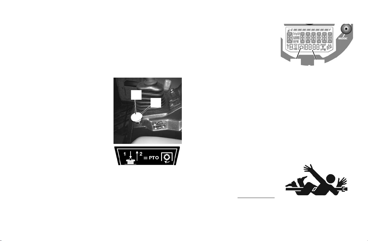
Power Take-Off (PTO) (Model HDPTO)
1
2
3
4
Description
The front PTO is standard equipment on the HD
only.
The PTO must be in the disengaged (OFF) position before the
engine can be started.
The PTO has a rated speed of 2000 RPM.
WARNING!
Avoid Injury Or Death
• Do Not exceed the rated attachment PTO speed.
• Stay clear of rotating driveline
• Keep bystanders away.
• Keep hands, feet, clothing and long
hair away.
• Keep PTO shields and guards in
place.
• Disengage PTO, put gear selector
in PARK, stop the engine and
make sure all rotating components
are stopped before exiting utility
vehicle.
• Do Not servic e the utility vehicle or
attachment with the PTO engaged.
• Do Not service the attachment in a raised position unless properly
• Disengage PTO for road travel.
blocked and all rotating components stopped.
Engaging PTO
Tip: Do not engage the PTO system at higher engine rpm with the
attachment under load. Always engage the PTO system at a
lower engine rpm an d with the attachmen t u nde r a no l oa d c ond ition.
PTO model
OPERATION
The operator must be in the operator seat to engage the PTO system. (If the o perator exits the
machine with the PTO engaged,
the PTO will shut off.)
Reduce the engine speed.
On the PTO switch, press the
center button (Item 1) and then
pull up on the knob (Item 2) to engage the PTO.
The light (Item 3) in the dash will illuminate and the PTO shaft
will start rotating. The PTO RPM (Item 4) will be displayed.
Increase the engine speed to t he desired rpm spe cified for your
attachment. See your attachment Owner’s Manual for the correct PTO rpm.
Disengaging PTO
Reduce th e engine speed to low idle.
Press down on the PTO switch (Item 2) to the disengaged
(OFF) position. The light (Item 1) in the dash will tur n OFF
and the PTO shaft will stop rotating.
WARNING!
Avoid Injury Or Death
• Keep PTO shield and all guards
in place.
• Keep away from moving parts.
• Keep bystanders away.
• Do NOT exceed 2000 PTO RPM
.
47
Page 49
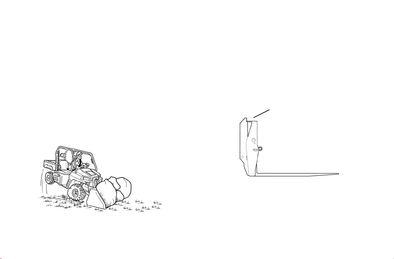
OPERATION
Decal
Attachments (Models HD and HDPTO)
Choosing The Correct Attachment
WARNING! Avoid Injury or De ath. Never u se att ac hment s o r buck ets
which are not approved by Polaris. Buckets and attachments for safe
loads of specific densities are approved for each mode l. U nap prov ed
attachments can cause injury or death.
Tip: Any damage caused by the use of non-approved attachments is
not covered by warranty.
The dealer can identify, for the utility vehicle, the attachments
and buckets approved by Polar is. The bucket s and atta chments
are approved for attachment arm rated capacity and for secure
fastening to the PRO-TACH.
The attachment arm rated capacity is determined by using a
standard bucket and mater ia l of nor mal density, such as dirt or
dry gravel. If very dense materi al is loaded, the volume must
be reduced to prevent overloading.
• Longer stopping distance
• Faster tire wear
• Loss of stability
• Reduced utility vehicle life
Use the correct si ze buc ket for the t ype and densit y of mat erial
being handled. For safe handling of materials and avoiding
vehicle damage, the attachment (or bucket) should handle a
full load withou t goi ng over the attachment arm rated capacity
for the utili ty vehicle.
Choosing The Correct Attachment
Exceeding the arm rated capacity can cause the following
problems:
• Difficult Steering
48
If a pallet fork attachment is use d, the load center moves forward and reduces the load capacity.
The maximum load to be carried when using a pallet fork is
shown on a decal located on the pallet fork frame.
See your dealer for more information about pallet fork inspection, maintenance and replacement. See your dealer for attachment arm rated capaci ty when using a pallet for k a nd f or ot her
available attachments.
Page 50
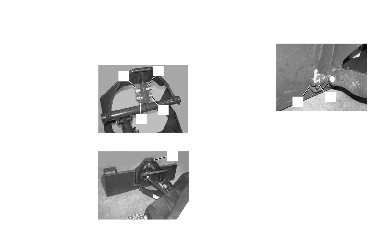
Attachments (Models HD and HDPTO)
2
1
2
1
3
5
4
Installing And Removing Attachments
The PRO-TACH attachment system is used for fast changing
of buckets and other attachments. See the appropriate
Attachment Owner’s Manual to install other attachments.
Installing:
1. Remove the two
retainers (I tem 1) and
pins (Item 2) from the
storage position.
2. Start the engine. See
page 41. Move the
gear selector lever to
LOW.
3. Lower the attachment
arm ant tilt the attachment interface forward.
4. Slowly drive forward
until the front edge of
the attachment interface is compl etely
under the top l ip of the
attachment (Ite m 3).
5. Tilt the attachment
interface backward
until the attachment is
slightly off the ground.
6. Move the gear selector lever to PARK and stop the engine. See page 41.
OPERATION
7. Install the two pins
(Item 1) and retainers
(Item 2) (both sides).
8. Connect the auxiliary
hydraulic hoses (if
equipped). See page
46.
9. Connect the PTO
driveline (if equipped).
See page 51.
49
Page 51
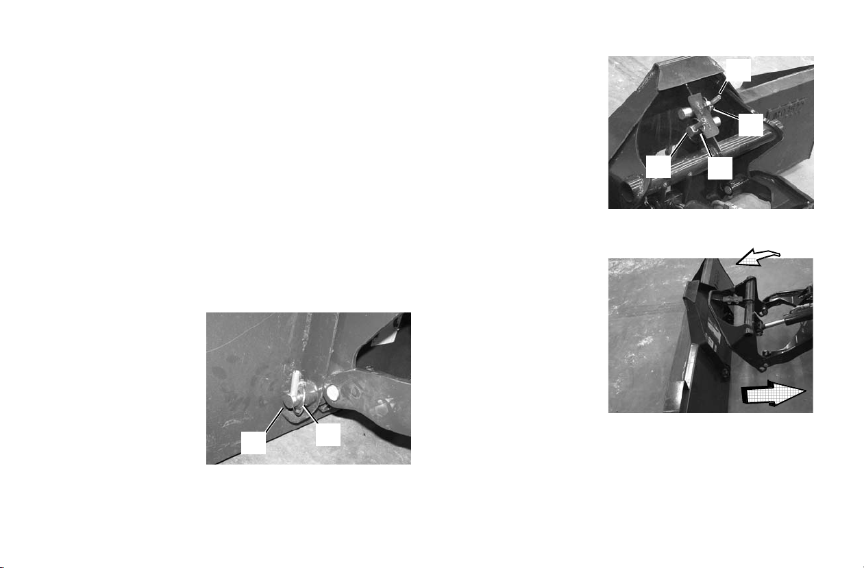
OPERATION
2
1
3
3
4
4
Attachments (Models HD and HDPTO)
Installing And Removing Attachments
Removing:
Tip: In muddy conditions or to prevent the a ttachmen t from freezing to
the ground, put the attachment on planks or blocks before
removing the attach ment from the vehicle.
1. Lower the attachment arm and put the attachment flat on
the ground
2. Move the gear selector leve r to PARK and stop the engine.
See page 41.
3. If the attachment is hydraulically controlled, (snowblade,
etc.), relieve the hydraulic pressure at the quick couplers.
See page 46.
4. Disconnect the auxiliary hydraulic quick couplers. (if
equipped). See page 46.
5. Disconnect the PTO
driveline (if equipped).
See page 51.
6. Remove the two
retainers (I tem 1) and
pins (Item 2) (both
side).
7. Install the two pins
(Item 3) and retainers
(Item 4) into the storage position.
8. Start the engine. See
page 41. Move the
gear selector lever to
LOW.
9. Be sure the attachment is fully lowered
and the attachment is
flat on the ground.
10. Tilt the attachment
interface forward.
Move backward, away
from the attachment.
WARNING! Avoid Injury Or
Death. Before you leave the
operators seat:
• Park on flat level ground.
• Lower the attachment arm,
put the attachment flat on
the ground.
• Press the brake pedal and move the gear selector lever to PARK.
• Disengage the PTO (if equipped) and make sure all rota ting com-
ponents are completely stopped.
• Stop the engine and remove the key.
50
Page 52

Power Take-Off (PTO) (Models HDPTO)
Installing And Removing The PTO
The BRUTUS Model HD
The PTO has a rated speed of 2000 RPM.
WARNING!
Avoid Injury or Death
• Do Not exceed the rated attachment PTO speed.
• Stay clear of rotating driveline.
• Keep bystanders away.
• Keep hands, feet, clothing and long hair away.
• Keep PTO shields and guards in place.
• Disengage PTO, put gear selector in PARK, stop the engine and
make sure all rot ating component s are stoppe d before exi ting utility
vehicle.
• Do Not service the utility vehicle or attachment with the PTO
engaged.
• Do Not service the attachment in a raised position unless properly
blocked and all rotating components stopped.
• Disengage PTO for road travel.
Installing
Install the attachment to the utility vehicle. See page 48.
Stop the engine and exit the vehicle. See page 41.
Make sure the PTO dri veline and all rotat ing component s have
come to a complete stop before exiting the vehicle.
NOTICE: Avoid PTO Driveline Damage
• Do not modify the attachment arm or PTO driveline.
• Make sure PTO driveline is the correct lengt h and that the ujoints are in the correct phase.
• Use only approved PTO drivelines desi gnated fo r the a ttach ment and never use unapproved attachments.
PTO is factory equipped with a PTO.
OPERATION
WARNING!
Rotating Parts Can Cause Serious Injury Or Death
• Disengage the PTO, put the gear selector in PARk, stop the engine
and make sure all rotating components are completely stopped
before connecting, disconnecting, adjusting or cleaning any PTO
driven equipment.
• Always keep PTO shields and all guards in place when using the
PTO driven equipment.
• Disengage PTO for road travel.
• Keep hands, feet, clothing and long hair away.
WARNING!
Driveline Entanglement Or Overspeeding PTO Can Cause Serious
Injury Or Death
• Do Not install an adapter between the utility vehic le PTO shaf t and
the attachment PTO driveline.
• An adapter can extend the driveline universal joint and connecting
yoke beyond the PTO shields.
• An adapter can overspeed the attachment PTO causing driveline
or attachment damage.
51
Page 53

OPERATION
1
2
Power take-Off (PTO) (Models HDPTO)
Installing And Removing The PTO
Installing (Con’d)
Each attachment has a specific length PTO drive
shaft that is affixed to the
attachment. Do not intermix or replace drive sha ft s
or components between
different attachment types.
Connect th e PTO driveline (Item 1 ) to the PTO
shaft of the utility vehicle.
Make sure it is securely
connected by pushing and pulling on the driveline. See your
attachment Owner’s Manual for additional information.
Tip: The PTO driveline must have a means to retain it to the PTO
shaft on both the utility vehicle and the attachment.
WARNING! Avoid Injury or Death
• Keep PTO shields and guards in place.
• Keep away from moving parts.
• Keep bystanders away.
• Do Not exceed 2 000 PTO RPM
.
Removing
Stop the engine and exit
the utility vehicle. See
page 41.
Make sure the PTO driveline and all rotating components have come to a
complete stop before exiting the utility vehicle.
Disconnect the PTO driveline (Item 1) from the utility vehicle. See your attachment
Owner’s Manual for additional information.
WARNING! Rotating Parts Can Cause Serious Injury Or Death
• Disengage the PTO, put the gear selector in PARk, stop the engine
and make sure all rotating components are completely stopped
before connecting, disconnecting, adjusting or cleaning any PTO
driven equipment.
• Always keep PTO shields and all guards in place when using the
PTO driven equipment.
• Disengage PTO for road travel.
• Keep hands, feet, clothing and long hair away.
52
Page 54
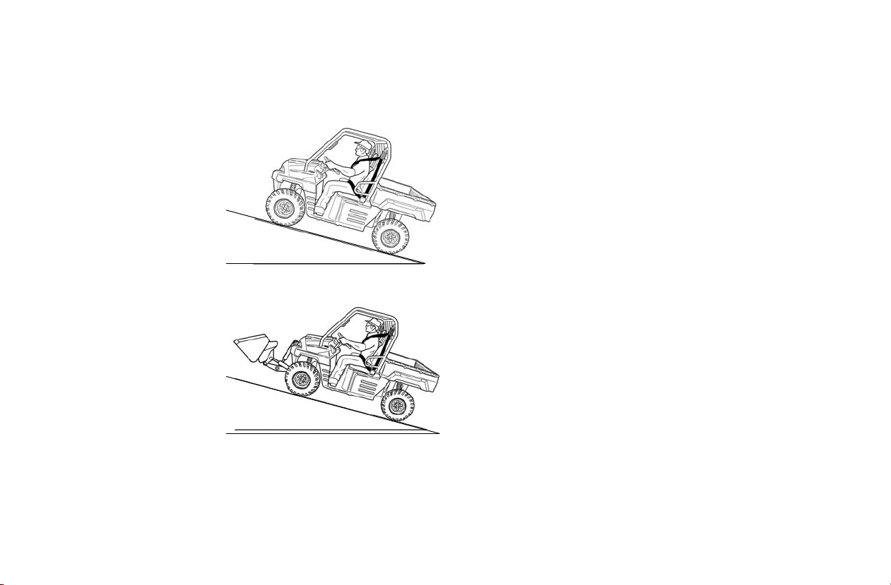
Driving Uphill
15° maximum
BRUTUS
15° maximum
HD and HDPTO
Whenever traveling uphill, follo w these precautions:
1. Always travel straight
uphill.
2. Avoid steep hills (15°
maximum). For model
HD and HD
the heavy end of the
vehicle uphill.
3. Keep both feet on the
floor.
4. Always check the ter-
rain carefully before
ascending any hill.
5. Never climb hills with
excessively slippery
or loose surfaces.
6. Proceed at a steady
rate of speed. Never
move the travel control pedal or change
direction of travel
suddenly.
7. Never go over the cres t of a hill at high speed. An obstacl e,
a sharp drop, or another vehicle or person could be on the
other side of the hill.
PTO: Keep
OPERATION
Stalling While Climbing A Hill
Stalling or rol ling backwar ds while cl imbing a hil l could caus e
overturn. Always maintain a steady speed whe n cl imbi ng hills.
If All Forward Speed Is Lost:
1. Apply the brakes.
2. Place the transmission in neutral and slowly allow the
vehicle to roll stra ight do wnhill whil e applying light bra ke
pressure to control speed.
If you Begin Rolling Downhill:
1. Never apply engine power.
2. Decelerate using the travel control pedal and apply the
brake gradually until the vehicle is fully stopped.
3. Place the transmission in neutral and slowly allow the
vehicle to roll stra ight do wnhill whil e applying light bra ke
pressure to control speed.
Driving on a Sidehill (Sidehilling)
Driving on a sidehill is no t recommended. I mproper proc edure
could cause los s of con trol or overtur n. Avoid crossing the side
of any hill unless absolutely necessary.
If crossing a sidehill is unavoidable, follow these precautions:
1. Slow down.
2. Exercise extreme caution.
3. Avoid crossing the side of a steep hill (15° maximum).
53
Page 55
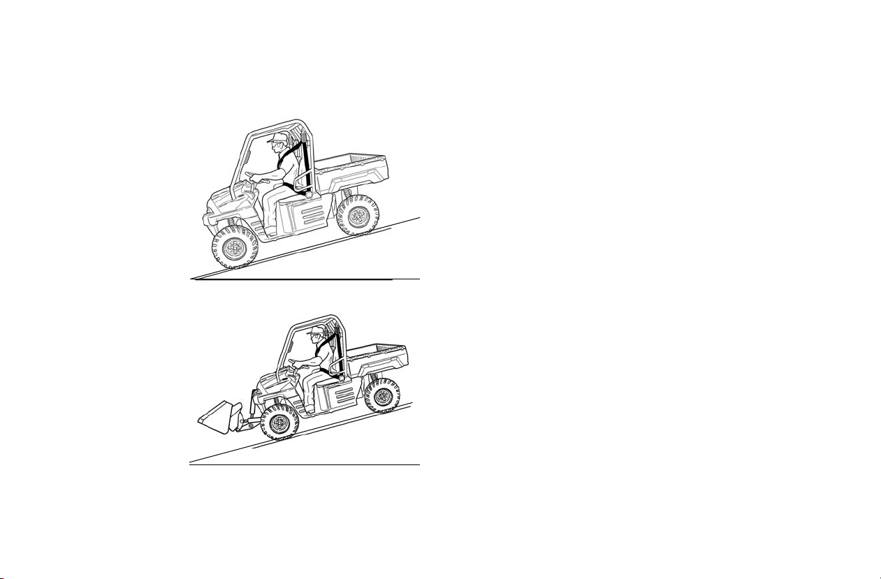
OPERATION
15° maximum
BRUTUS
HD and HD
PTO
15° maximum
Driving Downhill
When driving downhill, follow these precautions:
1. Avoid steep hills
(15° maximum).
2. Drive straight
downhill. Avoid
descending a hill at
an angle, which
would cause the
vehicle to lean
sharply to one side.
Travel straight
downhill when
possible. For
model HD and
HDPTO: Keep the
heavy end of the
vehicle uphill.
3. Slow down.
4. Apply the brakes
slightly to aid in
slowing.
54
Page 56

OPERATION
WARNING
Sideways
skid
Turn in
direction of
skid
Driving on Slippery Surfaces
Skidding or sliding can cause loss of control or overturn (if tires regain traction unexpectedly). When operating on slippery surfaces suc h as ic e
or loose gravel, reduce speed and use extra caution to reduce the chance of skidding or sliding out of control. Do not operate on excessively
slippery surfaces.
Whenever riding on slippery surfaces such as wet trails or loose gravel, or during freezing weather, follow these precautions:
1. Do not operate on excessively rough, slippery or loose terrain.
2. Slow down before entering slippery areas.
3. Maintain a high level of alertness, reading the trail and avoiding quick, sharp turns, which can cause skids.
4. Engage all-wheel drive before wheels begin to lose traction.
NOTICE: Severe damage to the drive train may occur if the AWD is engaged while the wheels are spinning. Always allow the wheels to stop
5. Correct a skid by turning the steering wheel in the direction of the skid. Never apply the brakes during a skid.
spinning before engaging AWD.
55
Page 57

OPERATION
BRUTUS
HD and HD
PTO
Driving Over Obstacles
Follow these precautions when operating over obstacles:
1. Always check
for obstacles
before operating in a new
area.
2. Look ahead and
learn to read the
terrain. Be constantly alert for
hazards such as
logs, rocks and
low hanging
branches.
3. Travel sl owly
and use extra
caution when
operating on
unfamiliar terrain. Not all
obstacles are
immediately visible.
Tip: For model HDPTO: When driving over objects (example: a curb),
always drive at a slight angle and at slow speed to allow one
wheel at a time to go over the object. This will allow maximum
ground clearance fo r the util ity ve hic le and avo id PT O s ha ft dam age.
56
Driving in Reverse
Follow these precautions when operating i n
reverse:
1. Always check for
obstacles or people
behind the vehicle.
Always inspect left
and right fields of
vision before backing. Always look in
the direction of
travel.
2. Always avoid backing downhill.
3. Back slowly.
4. Decelerate using the travel control pedal and apply the
brakes lightly for stopping.
5. Avoid turning at sharp angles.
6. Never move the travel control pedal suddenly.
Page 58

Driving Through Water
Floorboard
Your POLARIS BRUTUS can operate through water up to a
maximum recommended depth equal to the floorboards.
NOTICE: Driving through water deeper than the floorboards will
NOTICE: Immersion can result in major damage if the vehicle isn't
Tip: For model HD and HD
Follow these procedures when
operating through
water:
1. Determine
cause engine damage and will also void the engine
warranty.
serviced correctly and promptly. After immersion, always
take the vehicle to a your dealer for service. Do not start
the engine! If it's impossible to bring the vehicle to your
dealer before starting the engine, perform the service
outlined on page 93, and take the v eh ic le t o y our dea ler at
the first opportunity.
PTO; It is not recommended to drive
through water with an attachment installed.
water depths
and current
before entering water.
OPERATION
2. Choose a crossing where b oth banks have gra dual in cline s.
3. Proceed slowly, avoiding rocks and obstacles.
4. Avoid operating through deep or fast-flowing water.
WARNING! The large tires on your BRUTUS may cause the vehicle
to float in deep or fast-flowing water, which could result in loss of
control and lead to serious injury or death. Never cross deep or fastflowing water with your BRUTUS.
5. After leaving water, always dry the brakes by applying
light pressure to the pedal repeatedly until braking action
is normal.
NOTICE: After operating the vehicle in water, it's critical that you
perform the services outlined in the Periodic Maintenance
Chart beginning on page 77. Give special attention to
engine oil, transmission oil, all gearcase fluids and all
grease fittings.
57
Page 59

OPERATION
15° maximum
Parking the Vehicle
1. Press the brake pedal until the utility vehicle comes to a
complete stop. Stop the vehicle on a level surface.
2. When parking inside a garage or other structure, be sure
that the structure is well ventilated and that the vehicle is
not close to any source of flame or sparks, including any
appliance with pilot lights.
3. For models HD and HD
arm and put the attachment flat on the ground.
4. Move the gear selector lever to Park.
5. For models HD and HD
control lever to low idle. Disengage the PTO and make
sure all rotating components are completely stopped.
6. Turn the engine off and remove the key to prevent unau-
thorized use.
PTO only: Lower the attachment
PTO only: Move the engine speed
Parking on
an Incline
Avoid parking on
an incline if possible. If it's
unavoidable, follow these precautions:
1. Apply the
brakes.
2. Place the
transmission
in PARK.
3. Turn the engine off.
4. Block the rear wheels on the downhill side.
58
Page 60

OPERATION
WARNING
Hauling Cargo
Hauling cargo impro perly can al ter vehi cle ha ndlin g and m ay ca use lo ss of c ontrol or brake inst abil ity, which can result in serio us inj ury or d eath.
Always fol low these precautions when hauling cargo:
Never exceed the vehicle rated capacity or the total rated capacity. When determining the weight you are adding to the vehicle, include the
weight of the operator, passenger, accessories, attachments (models HD and HD
The combined weight of these items must not exceed the vehicle rated capacity.
REDUCE SPEED AND ALLOW GREATER DISTANCES FOR BRAKING WHEN HAULING CARGO.
Always load the cargo box with the load as far forward and as low as possible.
When operating over rough or hilly terrain, reduce speed and cargo to maintain stable driving conditions.
Always operate the vehicle with extreme care when hauling or towing loads.
Slow down and drive in the lowest gear available.
SECURE ALL LOADS BEFORE OPERATING. Unsecured loads can create unstable operating conditions, which could result in loss of control of
the vehicle.
OPERATE ONLY WITH STABLE AND SAFELY ARRANGED LOADS. When handling off-centered loads that cannot be centered, securely
fasten the load and operate with extra caution. Always attach the tow load to the hitch point designated for your vehicle.
HEA VY LOAD S CAN CAUSE BRAKIN G AND CO NTROL PR OBLEMS. Use extreme c autio n when a pplyi ng bra kes with a loade d veh icle. A void
terrain or situations that may require backing downhill.
USE EXTREME CAUTION when operating with loads that extend over the rack sides. Stability and maneuverability may be adversely affected,
causing the vehicle to overturn.
WARNING! DO NOT TRAVEL FASTER THAN THE RECOMMENDED SPEEDS. Vehicle should
never exceed 10 MPH (16 km/h) while towing a load on a level grass surface. Vehicle speed
should never exceed 5 MPH (8 km /h ) wh en to wing loa ds in rou gh te rrain , w hil e c orne ring , or w hi le
ascending or descending a hill.
Driving with passengers in the cargo box can result in severe injury or death. Never allow
passengers to ride in the cargo box. Passengers must always ride in the cab with seat belts
fastened securely.
PTO Only), loads in the box and the load on the trailer tongue.
59
Page 61

OPERATION
A
B
C
D
E
Hauling Cargo
The BRUTUS has been designed to carry or tow specific capacities. Always read and understand the load distribution warnings
listed on the warning labels. The total load (operator, passenger, attachments, accessories, cargo and weight on hitch) must not
exceed the maximum weight capacity of the vehicle. Never exceed the following capacities.
Model Attachment Arm
BRUTUS Not Applicable 500 lbs. (225 kg) 1250 lbs. (567 kg) 150 lbs. (68 kg) 1750 lbs. (794 kg)
BRUTUS HD 500 lbs. (225 kg) 500 lbs. (225 kg) 1250 lbs. (567 kg) 150 lbs. (68 kg) 2000 lbs. (907 kg)
BRUTUS HD
A
A - Attachment Arm Rated Capacity * = 500 lb (225 kg) Maximum
B - W e ig ht of Oc c upant(s) = 500 lb (225 kg) Maxim um
C - Maximum Cargo Box Load = 1250 lb (567 kg)
D - Maximum Trailer Hitch Tongue Weight = 150 lb (68 kg)
E - Tow Weight (Level Ground) = 2000 lb (907 kg) (includes weight of trailer)
Vehicl e Rated Capacity = A plus B plus C plus D = (BRUTUS and BRUTUS HDPTO) 1750 lb (794 kg) / (BRUTUS HD) 2000 lb (907 kg) Maximum
* Attachment Arm Rated Ca pacity is determined by using the standard bucket and material of normal de nsity, such as dirt or dry gravel. If other attachments,
such as Pallet forks are used, the load is moved forward and the attachment arm capacity is reduced. If very dense materi al is loaded, the volume must be
reduced.
60
PTO 500 lbs. (225 kg) 500 lbs. (225 kg) 1250 lbs. (567 kg) 150 lbs. (68 kg) 1750 lbs. (794 kg)
Rate Capacity
Passenger
Compartment
Maximum Cargo Box
Weight Capacity
Maximum Trailer
Hitch To ngue W eigh t
Vehic le Rated
Capacity
Page 62

OPERATION
Towing Loads
Towing improperly can alter vehicle handling and may cause loss of con tr ol or brake instabilit y. Always follow these precautions
when towing:
1. Never load more than 150 lbs. (68 kg) tongue weight on the towing bracket.
2. Use low range. Do not operate the vehicle faster than 10 MPH (16 km/h) when towing. See page 61. Towing a trailer
increases braking dist anc e.
3. Do not tow more than the recommended weight for the vehicle. See the towing capacity chart on previous page and the specifications charts beginning on page 59.
4. Attach a trailer to the trailer hitch bracket only. Do not attach a trailer to any other location or you may lose control of the
vehicle.
5. Never tow a trailer on a grade steeper than 15°.
61
Page 63

OPERATION
Release Lever
1
Dumping the Cargo Box
1. Select a level site to dump
the cargo box. Do not
attempt to dump or unload
the vehicle while parked
on an incline.
2. Apply the brakes.
3. Place the transmission in
gear.
4. Engage the park brake.
5. Dismount the vehicle.
6. Ensure that the cargo is
positioned evenly or
toward the front of the cargo box.
7. Release the tailgate by pulling up on the tailgate latch.
WARNING! If the weight distributi on on the box is loca ted tow a rd th e
rear of the box when the release lever is pulled forward, the box may
dump unexpectedly and cause serious injury to the operator or
bystanders. Never operate the dump lever without ensuring that the
load is positioned evenly or at the front of the box.
8. Stand clear and pull up on the cargo box release lever.
9. Lift the front of the cargo box to dump the cargo.
10. Lower the cargo box and push down securely to latch.
WARNING! Operating the vehicl e while the cargo b ox is raised c ould
result in severe injury. The box could close unexpectedly and cause
injury to the driver or pas seng er. The rear tires will also catch the rear
of a raised box, d am agi ng the ve hic le and creating haza rdou s d r iv ing
conditions. Never opera te this vehicle with the cargo box in the raised
position.
Dumping The Cargo Box (With Power Lift Assist)
Press the top of the switch (Item 1) to raise the cargo box.
Press the bottom of the switch (Item 1) to lower the cargo box.
62
Page 64
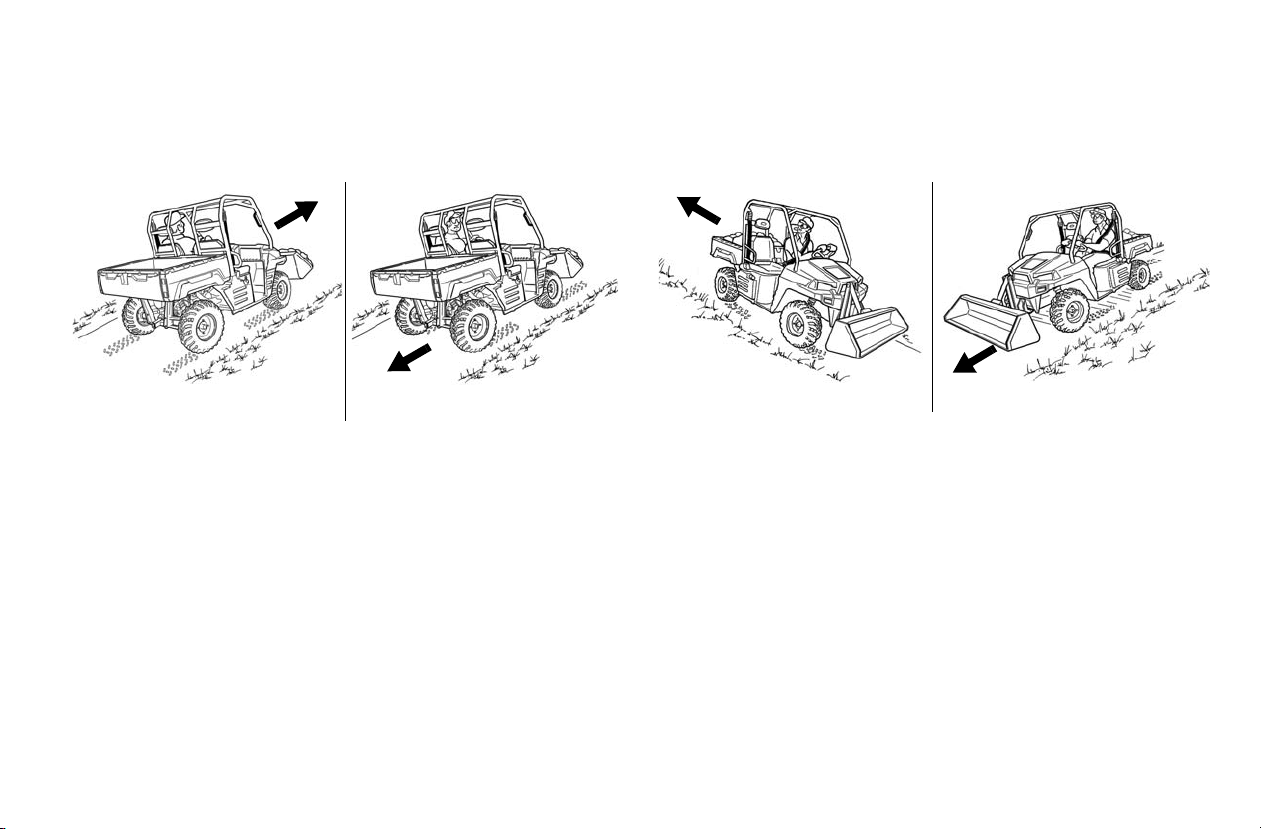
Operating With A Full Bucket And Empty
Loaded Bucket And Empty Cargo Box
Going Up Slope Going Down Slope
Loaded Bucket And Empty Cargo Box
Going Up Slope
Going Down Slope
Cargo Box
OPERATION
Operating With An Empty Bucket And
Loaded Cargo Box
With a loaded bucket and an empty cargo box, go up or down
the slope with th e he avy end toward the top of the slope. Look
in the direc tion of travel.
With an empty bucket and a loaded cargo box, go up or down
the slope with the heavy end toward the top of the slope. Look
in the direction of travel.
WARNING! Vehicle Tipping Or Rollover Can Cause Se riou s Inj ury or
Death
• Keep the attachment arm as low as possible.
• Turn on level ground. Slow down when turning.
• Go up and down slopes, not across them.
• Keep the heavy end of the vehicle uphill.
• Do not exceed vehicle load capacity.
• Check for adequate traction.
Raise the bucket only high enough to avoid obstructions on
rough ground.
Tip: When both ar empty or when both are loaded, the front and rear
of the vehicle are cl os e to the same weight. You can either move
forward or backward up and down the slope.
63
Page 65

OPERATION
A
B
C
D
A
B
C
D
A
B
C
D
Filling And Emptying The Bucket
Filling
Lower the attachment arm all the way (Item A) and tilt th e
bucket forward (Item D) until the cutting edge is on the
ground. Drive slowly forward to push the bucket slightly into
the material.
Raise the attachment arm (Item B) and tilt the bucket backward (Item C).
WARNING!
Avoid serious Injury Or Death
Load, unload and turn on flat level ground. Do not exceed vehicle
load capacity shown on sign (decal) in cargo box. Failure to obey
warnings can cause vehicle rollover and can cause serious injury or
death.
Drive backward away from the ma terial.
Emptying
Keep the bucket low when moving to t he area where you want
to dump the material.
Move the machine slowly to the dump area.
While raising the attachment arm (Item B), tilt the bucket forward (Item D ) to keep it level and help prevent material from
falling off the back of the bucket.
Tilt the bucket al l the way forward (Item D) to empty the
bucket.
64
Page 66
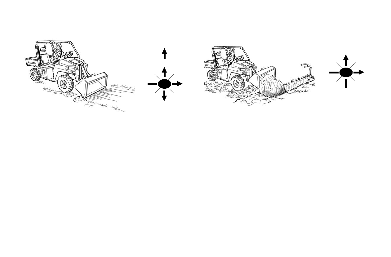
Leveling The Ground Using Float
A
B
C
D
AA
A
B
C
D
Raise the attachment arm (Item B) and tilt the bucket forward
(Item D).
Push the joystick all the way forward (Item AA) to activate
float.
NOTICE: Never drive forward when the attachment arm is in the
Drive backw ard to level loose material.
Pull the joystick backward (Item B) to unlock the attachment
arm from the float position.
float position.
OPERATION
Backfilling
Lower the attachment arm (I tem A) and put the cutting e dge of
the bucket on the ground (Item D). Drive forward to the edge
of the hole to push the material into the hole.
Tilt the bucket forward (Item D) as soon as it is past the edge
of the hole.
If necessar y, raise the li ft arms to empty the bu cket.
65
Page 67
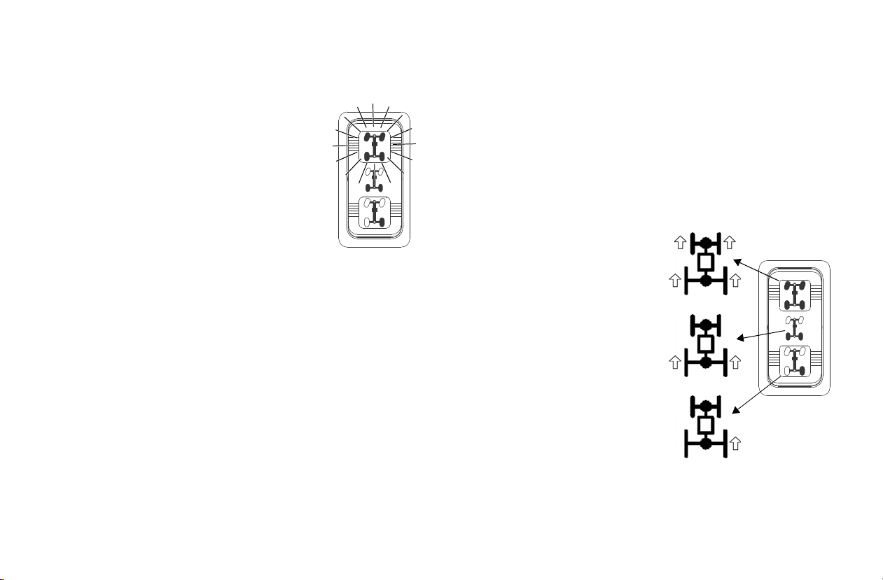
OPERATION
All Wheel Drive (AWD)
Engaging AWD
Press the top of the rocker switch t o engage
All Wheel Drive (AWD). The illuminated
amber AWD switch indicates that the vehicle
is in AWD.
When the AWD switch is on, the front wheels
will automatically engage any time the rear
wheels lose traction. When the rear wheels
regain traction, the front wheels will automatically disengage . There is no limi t to the length
of time the vehicle may remain in AWD.
Tip: The AWD switch may be turned on or off while the vehicle is
moving.
Engage the AWD before getting into conditions where front
wheel drive may be needed. If the rear wheels are spinning,
release the travel control pedal before switching to AWD.
NOTICE: Switching to AWD while the rear wheels are spinning may
cause severe drive shaft and clutch damage. Always
switch to AWD while the rear whee ls have tractio n or are at
rest.
Disengaging AWD
Move the AWD switch to the center or bottom position to disengage AWD. If the switch is turned off while the front hubs
are driving , they will not release until the rear wheels regain
traction.
In some situations, the front gearcase may remain locked after
turning the AWD switch off. If th is occurs, you may notice
increased steering effort and some vehicle speed restriction.
Perform the following procedure to unlock the front gearcase.
1. Stop the veh i cle. Operate in rever se for at least 10 feet (3
m).
2. Stop compl etely. S hift into low gear and d rive forward.
3. If the front gearcase remains locked after followin g these
instructions, see your dealer for service.
Locking the Differential
NOTICE: Damage to the differe nti al
can occur if it is engaged
while the vehicle is
traveling at high spee ds or
while the rear wheels are
spinning. Slow the v ehicl e
to nearly stopped before
engaging the differential.
Locking the differential in slippery or low traction conditions
helps improve traction. Move the
rocker switch to the center position (2WD) t o lock the differential and operate in rear wheel
drive.
Press the bottom of the switch to
unlock the differential and allow the rear drive wheels to operate independently. This mode of operation is well suited to tur f
driving or whenever aggressive traction is not required.
66
Page 68

Safety Rules For PTO Operation (HDPTO)
WARNING!
Avoid Injury Or Death
• Do Not exceed the rated attachment PTO speed.
• Stay clear of rotating driveline.
• Keep bystanders away.
• Keep hands, feet, clothing and long hair away.
• Keep PTO shields and all guards in place.
• Disengage PTO, put transmission in Park, stop the engine and
make sure all rot ating component s are stoppe d before exi ting utility
vehicle.
• Do NOT service the utility vehicle or implement with the PTO
engaged.
• Do NOT service the implement in a rais ed po si tion unless prope rly
blocked and with all rotating components stopped.
• Disengage PTO for road travel.
WARNING!
Avoid Injury Or Death
Before you leave the operator’s seat:
• Park on flat level ground.
• Lower the attachment arm, put the attachment flat on the ground.
• Press the brake pedal and move the gear selector lever to PARK.
• Disengage the PTO and make sure all rotating components are
completely stopped.
• Stop the engine and remove the key.
WARNING!
Avoid Injury Or Death
Warnings and instructions in this manual and on the machine are for
your protection.
Failure to follow the warnings and instructions can cause serious
injury or death.
OPERATION
• Keep all shields in place. Replace damaged or missing shields
before operating
• Follow warnings and instructions on machine signs (decals).
Replace damaged or missing dec als .
• Do not wear loose or bulky clothing around the PTO or other moving parts.
• Keep bystanders away from PTO driven equipment, and never
allow children near machines.
• Read and understand the manuals for the PTO driven equipment
and be aware of safe operating procedures and hazards that may
not be readily apparent.
• Always walk around equipment to avoid coming near a turning
PTO driveline. Stepping over, leaning across or crawling under a
turning PTO driveline can lead to entanglement.
• Do not install an adapter between the machine PTO shaft and the
attachment PTO driveline.
• Never overspeed the PTO. See attachment Owner’s Manual for
correct PTO speed.
• Position the machine and attachment correctly to prevent driveline
stress and separation.
• Use caution when raising PTO driv en att a chment. Excessive d riv eline angle can reduce driveline service life.
• Do not engage the PTO system at higher engine rpm with attachment under load. Always engage the PTO system at a lower
engine rpm and with attachment under a no load condition.
WARNING!
Driveline Entanglement Or Overspeeding PTO Can Cause Serious
Injury Or Death
• DO NOT install an adapter between the utility vehicle PTO shaft
and the attachment PTO driveline.
• An adapter can extend the driveline universal joint and connecting
yoke beyond the PTO shields.
• An adapter can overspeed the attachment PTO causing driveline
or attachment damage.
67
Page 69

OPERATION
Operating The PTO (HDPTO)
The BRUTUS HDPTO utility vehicle is factory equipped with
a PTO.
The PTO has a rated speed of 2000 RPM.
Read and understand the attachment Owner’s Manual and the
utility vehicle Owner’s Manual prior to installing or using any
attachment.
WARNING!
Avoid Injury Or Death
• Steering and braking can be affected by th e attachmen t, four wheel
drive and the rear differential lock. Do not exceed the rated lift
capacities.
• Always carry loads low. Slow down when turning.
Always inspect the utility vehicle and the attachment before
use. Inspect for damaged or loose parts, damaged or missing
PTO shields and guards.
New operato rs must operate the utility vehicle in an open area
without bystanders. Operate the controls until the utility vehicle can be handled at a efficient and safe speed for all conditions of the work area.
Check for safe operating speed, safe stopping distances and
braking characteristics that may be different with each type of
attachment. Know that when attachments are inst alled, the
utility vehicle braking distance increases.
Before beginning operation, inspect the work area for unsafe
conditions.
Look for drop-offs or rough terrain. Have underground utility
lines (gas, water, sewer, irrigation, etc.) located and marked.
Remove objects or other construction material that could damage the utility vehicle or cause personal injury.
Do not engage the PTO system at higher engine rpm with
attachment under load. Always engage the PTO system at a
lower engine rpm and with attachment under a no load condition.
WARNING!
Avoid Injury Or Death
• Do NOT exceed the rated attachment PTO speed.
• Stay clear of rotating driveline.
• Keep bystanders away.
• Keep hands, feet, clothing and long hair away.
• Keep PTO shields and all guards in place.
• Disengage PTO, put transmission in Park, stop the engine and
make sure all rot ating component s are stoppe d before exitin g utility
vehicle.
• Do NOT service the utility vehicle or implement with the PTO
engaged.
• Do NOT service the implement in a raised position u nless properly
blocked and with all rotating components stopped.
• Disengage PTO for road travel.
68
Page 70
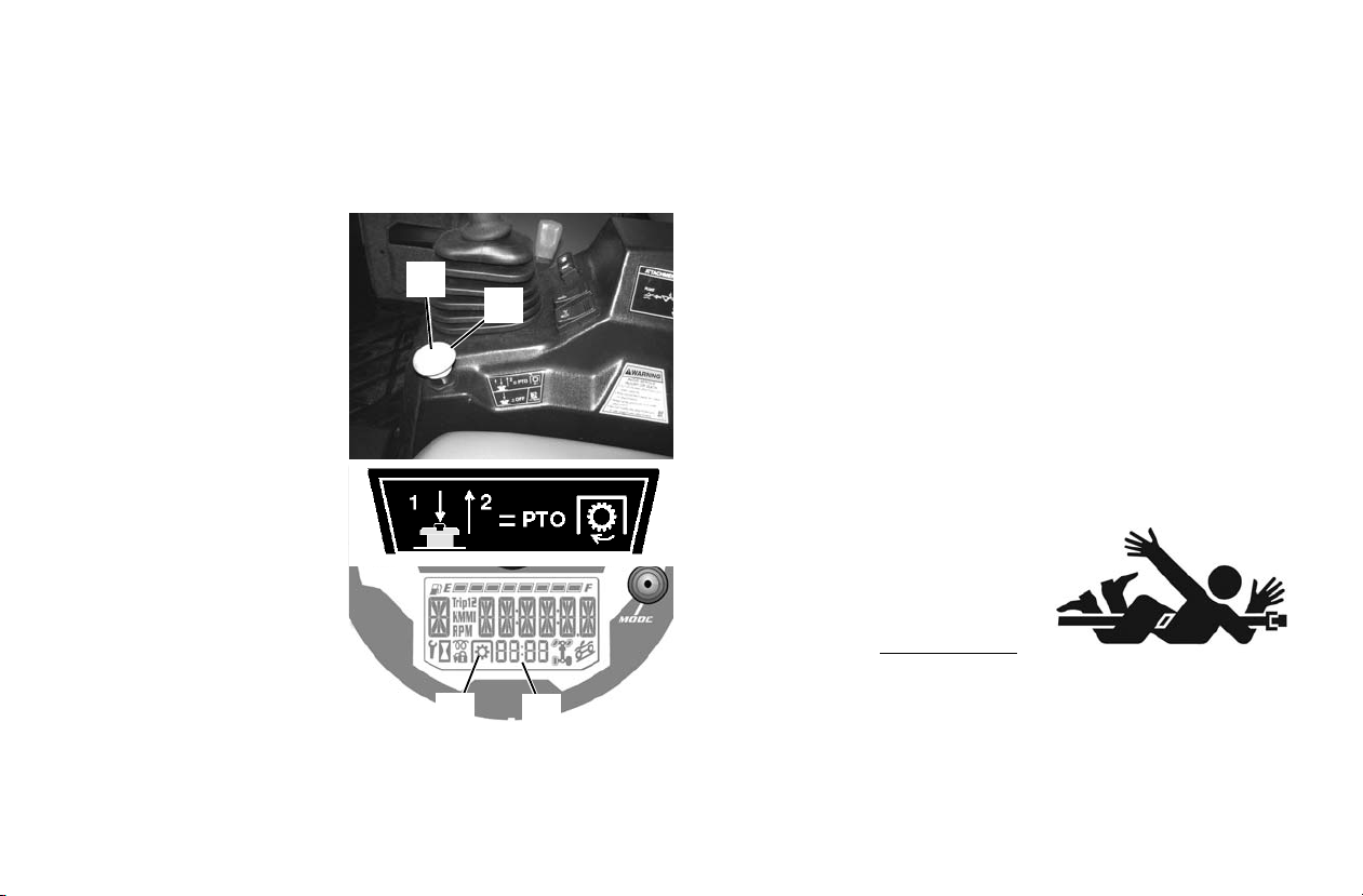
Operating The PTO (HDPTO)
2
1
4
3
See the attachment Owner’s Manual for the correct operating
procedure for your attachment.
Install the attachment on the utility vehicle. See pages 49.
Engaging PTO:
1. Start the engine. See
page 41.
2. Reduce the engine
speed.
Tip: Do not engage the PTO
system at higher engine
rpm with the attachment
under load. Always
engage the PTO system
at a lower engine rpm
and with the attachment
under a no load condition.
3. On the PTO switch,
press the center but ton
(Item 1) and then pull
up on the knob (Item
2) to engage the PTO.
4. The light (Item 3) in
the dash will illuminate and the PT O shaft
will start rotating. The
PTO shaft RPM will be displayed in the dash (Item 4).
OPERATION
5. Increase the engine speed to the desired rpm specified for
your attachment. See the attachment Owner’s Manual for
the correct attachme nt oper ating RPM. (With engine RPM
at 3600, the PTO shaft will rotate at approximately 2000
RPM. Adjust engine RPM to meet the attachment RPM
requirement.)
Tip: The maximum PTO speed for various attachments may vary.
See the attachment Owner’s Manual for the maximum speed
recommended for your attachment.
Tip: When driving over objects (example: a curb), always drive at a
slight angle and at slo w sp eed to allow one wheel at a time to go
over the object. This will allow maximum ground clearance for
the utility vehicle and avoid PTO shaft damage.
Tip: Do not engage the PTO system at higher engine rpm with the
attachment under load. Always engage the PTO system at a
lower engine rpm an d wi th the attachment unde r a n o l oad c ond ition.
WARNING!
Avoid Injury Or Death
• Keep PTO shield and all guards
in place.
• Keep away from moving parts.
• Keep bystanders away.
• Do NOT exceed 2000 PTO RPM
.
69
Page 71
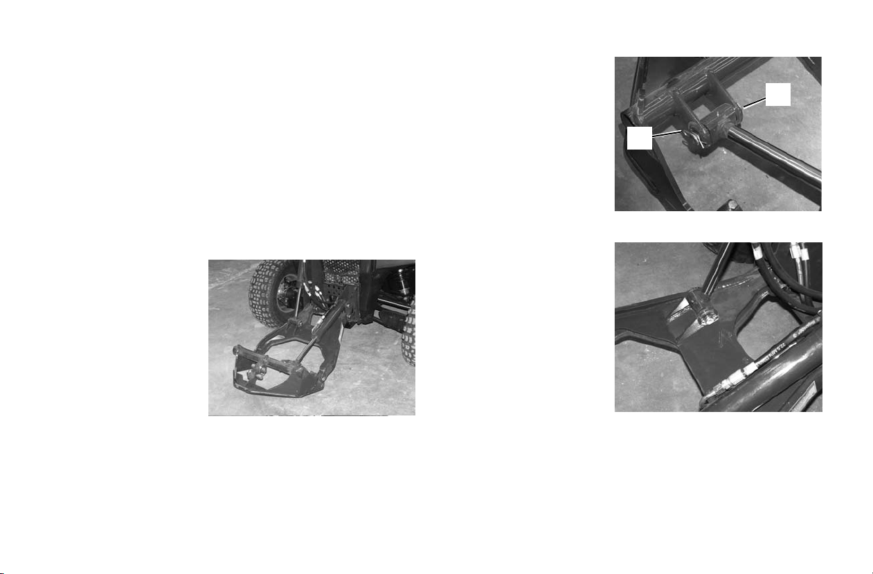
ATTACHMENT ARM
2
1
Removing And Installing (Models HD and
HD
PTO)
Description
When the PRO-TACH attachment system is not being used, it
can be removed from the vehicle.
Tip: Remove the bucket or attachment before removing the attach-
ment arm from the vehicle.
Removing:
Tip: Before removing the attachmen t arm, it is rec ommended to ins tall
the Tilt Cylinder Stow Kit. The stow kit will secure the tilt cylinder
in the storage position when the attachment arm is removed. See
your Polaris dealer for parts.
1. Park the vehicle on a
flat level su rface.
2. Lower the attachment
arm fully and tilt the
PRO-TACH fully forward.
Tip: In muddy conditions or to
prevent the attachment
arm from freezing to the
ground, put the attachment arm on planks or
blocks before removing
the attachment arm from the vehicle.
3. Move the gear selector leve r to PARK and stop the engine.
See page 41.
WARNING! Avoid Injury. Keep fingers and hands out of pinch points
when removing and installing the attachment arm.
Tip: When the pin (Item 2) is
removed from the tilt cylinder , the interfac e will be
free to tilt down to the
ground. Support the
interface while the pin is
being removed.
4. Remove the retainer
pin (Item 1) and the
pin (Item 2) from the
rod end of the tilt cylinder and position the
interface flat on the ground.
5. Remove the retainer
pin (Item 3) and pin
(Item 4) from the rod
end of the lift cylinder.
6. Start the engine. (See
page 41. Press the bottom of the joystick
lockout switch to
enable the joystick.
7. Retract both the lift
and tilt cylinders fully.
8. Press the top of the
joystick lockout switch to disable the joystick.
9. Turn the key to the off position and exit the vehicle. See
page 41.
70
Page 72
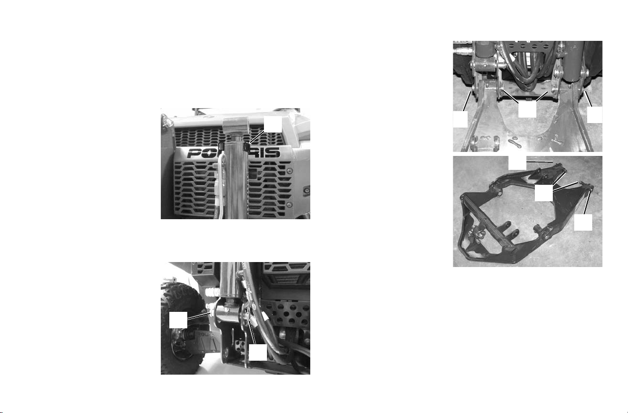
Removing And Installing (Models HD and
1
2
3
5
4
4
5
4
4
HD
PTO)
The PRO-TACH attachment system is used for fast changing
of buckets and other attachments. See the appropriate
attachment Owner’s Manual to install other attachments .
Removing (Cont’d):
Tip: The utility vehicle is
shown equipped with the
optional cylinder Stow Kit
(Item 1). See your Polaris
dealer for parts.
Rotate the tilt cylinder up
and into the storage position. Install the cylinder
into the Stow Ki t (Item 1)
(if equipped). If not
equipped with the Stow Kit cylinder retainer, a heavy tie strap
can be used to secure the cylinder to the grille in the storage
position.
Position the cyli nder to th e
frame and i nstall the pin
(Item 3) and the retainer
pin (Item 3) to secure the
lift cylinder in the storage
position.
ATTACHMENT ARM
Tip: When the pins (Item 5)
are removed from the
attachment arm, it will be
free to tilt down to the
ground. Support the
attachment arm w hile the
pins are being removed.
Remove the two retainer
pins (Item 4) and pins
(Item 5) and lower the
attachment arm fully.
Reinstall the pins (Item 5)
and the retain er pins (Item
4) into the attachment arm
for storage.
71
Page 73
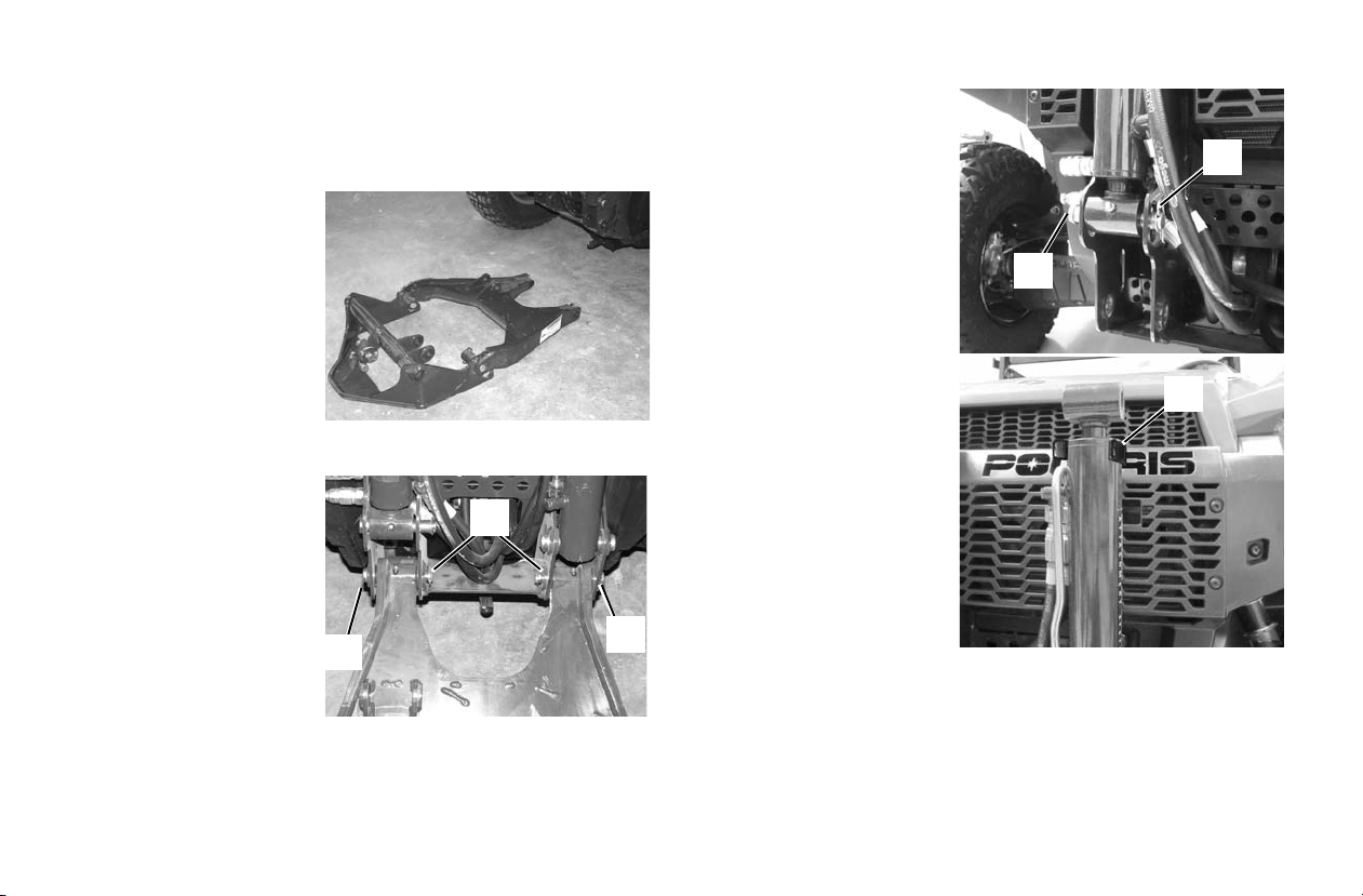
ATTACHMENT ARM
1
1
2
3
4
5
Removing And Installing (Models HD and
HD
PTO)
Installing:
WARNING! Avoid Injury.
Keep fingers and hands out of
pinch points when removing
and installing the attachment
arm.
1. Position the utility
vehicle so it is centered in front of the
attachment arm.
2. Remove the retainer
pins and pins from the
attachment arm (both sides).
3. Raise the attachment
arm and position it to
the vehicle mounting
frame. Install the two
pins (Item 1) and
retainer pins (Item 2).
4. Remove the lift cylinder retainer pin (Item
3) and the pin (Item 4).
5. Remove the tilt cylinder from the Stow Kit
(Item 5). Lower the tilt
cylinder down and rest
the rod end on the
attachment arm.
72
Page 74

Removing And Installing (Models HD and
2
1
3
4
HD
PTO)
Installing (Cont’d):
6. Start the engine. See page 41. Press the bottom of the joystick lockout switch to enable the joystick.
WARNING! Avoid Injury. Keep fingers and hands out of pinch points
when removing and installing the attachment arm.
7. Extend the lift cylinder full y.
8. Extend the tilt cylinder full y.
9. Press the top of the
joystick lockout swi tch
to lockout the joystick.
Turn the key to the
OFF position and exit
the utility vehicle.
10. Raise the interface
until it is aligned with
the rod end of the lift
cylinder . Install the pin
(Item 1) and retainer
pin (Item 2).
ATTACHMENT ARM
11. Rotate the interface
upward until it is
aligned with the rod
end of the tilt cylin der.
Install the pin (Ite m 3)
and retainer pin (Item
4).
Lubricate the attachment
arm and the cylinder
grease fittings. See page
120.
73
Page 75
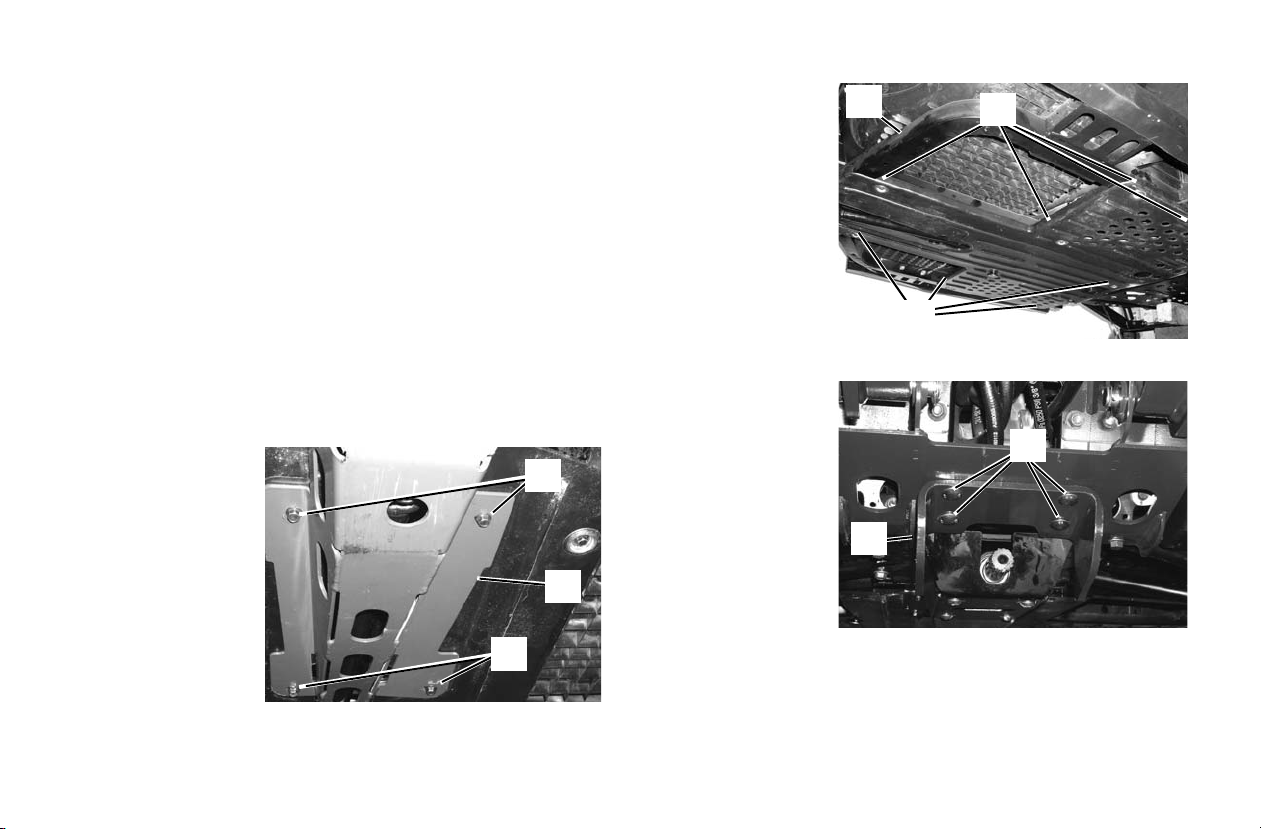
PTO SYSTEM
2
1
1
3
4
3
5
6
Removing And Installing PT O Shafts
(Models HD
Description
If the utility vehicle will not be used for PTO driven attachments for extended periods of time, it is possible to remove the
PTO drive shaft assembly from the PTO clutch. This will prevent damage to the PTO system if the utility vehicle will be
used off road or if additional ground clearance is desired.
Removing:
1. Stop the engine. See page 41.
2. Make sure the PTO driveline and all rotating components
have come to a complete stop before exiting the utility
vehicle.
3. Install the utility vehicle on jack stands. See page 111.
4. Remove the four
bolts (Item 1) and
remove the shield
(Item 2).
Installation: Tighten
the bolts to 7 - 8 ft-lb
(9 - 10 Nm) torque.
PTO)
5. Remove the
eight bolts (Item
3) and remove
the belly pan
(Item 4).
Installation: Tighten
the bolts to 7 - 8 ft- lb
(9 - 10 Nm) torque.
6. Remove the four
bolts and nuts
(Item 3) and
remove the guard
(Item 4).
Installation: Tighten
the bolts to 32 - 35 ftlb (43 - 47 Nm)
torque.
74
Page 76

Removing And Installing PT O Shafts
2
1
1
4
3
(Models HDPTO)
Removing (Cont’d):
7. Remove the
four bolts and
nuts (Item 1)
and remove the
PTO shaft carrier assem bly
(Item 2). (The
carrier assembly will nee to
be slide off the
PTO shaft
splines).
Installation:
Tighten the bolts to 32 - 35 ft-lb (43 - 47 Nm) torque.
8. Remove the passengers seat to
access the bolts
for the rear of
the PTO shaft.
Remove the four
bolts (Item 3 )
and remove the
PTO shaft (Item
4) from the PTO
clutch.
Installation: Tighten
the bolts to 18 - 19 ft-lb (24 - 26 Nm) torque.
9. Reinstall the belly pan after the PTO shaft has been
removed.
10. Place a ll the parts in a secure, dry area for installation at a
later date.
11. Remove the machine from the jack stands. See page 111.
12. The utility vehicle will now have additional ground clearance foe off road use.
Installing:
1. Stop the engine and exit the vehicle. See page 41.
2. Make sure the PTO driveline and all rotating components
have come to a complete stop before exiting the utility
vehicle.
3. Install the utility vehicle on jack stands. See page 111.
4. Apply grease to the driveshaft splines.
5. Remove the belly pan.
6. Install all parts in reverse order.
75
PTO SYSTEM
Page 77

EMISSION CONTROL SYSTEMS
Noise Emission Control System
Do not modify the engine, intake or exhaust components, as
doing so may af fect compli ance with U.S.A. EPA noise control
requirements (40 CFR 205) and local noise lev el requi rement s.
Operation on Public Lands in the U.S.A.
Y o ur POLARIS vehicle ha s a spark arrest er that was t ested and
qualified to be in accor dance with th e USFS standard 5100-1c.
Federal law requires that this spark arrester be installed and
functional when the vehicle is operated on public lands.
Operation of off- roa d veh ic les on publ i c la nds i n the U.S.A. is
regulated by 43 CFR 420. Violations are subject to monetary
penalties. Federal regulations can be viewed online at
www.gpoaccess.gov/ecfr/.
Exhaust Emission Control System
Exhaust emissions are controlled by engine design. A fuel
injection system controls fuel delivery. The engine and fuel
injection c omponents are set at the factory for optima l performance and are not adjustable.
Your engine is designed to operate on low sulfur or ultra low
sulfur diesel fuel onl y. Use of any other fuel may result in your
engine no longer operating in compliance with emissions
requirements.
Non-ionizing Radiation
This vehicle emits some electromagnetic energy. People with
active or non-active implantable medical devices (such as
heart monitoring or controlling devices) should review the
limitations of their device and t he applicable electromagnetic
standards that apply to this vehicle.
Electromagnetic Interference
This vehicle complies with the EMC requirements of European directives 97/24/EC and 2004/108/EC.
76
Page 78

Periodic Maintenance Chart
Careful periodic maintenance will help keep your vehicle in
the safest, most reliable condition. Inspection, adjustment and
lubrication of important components are explained in the periodic maintenance chart.
Inspect, clean, lubricate, adjust and replace parts as necessary.
When inspection reveals the need for replacement parts, use
genuine POLARIS parts av aila ble fr om your POLARIS dealer.
Record maintenance and service in the Maintenance Log
beginning on page 136.
Tip: Service and adjustments are important for proper vehicle opera-
tion. If you're not fam ili ar w i th s afe se rvi ce and adj us tme nt p roc edures, have a qualified dealer perform these operations.
Maintenance intervals in the following chart are based upon
average riding conditions and an average vehicle speed of
approximately 10 MPH (16 km/h). Vehicles subjected to
severe use must be inspected and servi ced more frequently.
MAINTENANCE
Severe Use Definiti on
• Frequent immersion in mud, water or sand
• Racing or race-style high RPM use
• Prolonged low speed, heavy load operation
• Extended idle
• Short trip cold weather operation
Pay special attention to the oil level. A rise in oil level during
cold weather can indicate contaminants collecting in the oil
sump or crankcase. Change oil immediately if the oil level
begins to rise. Monitor the oil level, and if it continues to rise,
discontinue use and determine the cause or see your dealer.
Maintenance Chart Key
► = Perform these operations more often for vehicles subjected to severe use.
E = Emission-related servi ce (Failur e to conduc t this main tenance will not void the emissions warranty but may affect
emissions.)
D = Caution: Due to the nature of these adjustments, it is recommended this service be performed by an authorized
POLARIS dealer.
Tip: Inspection may reveal the need for replacement parts. Always
use genuine Polaris parts.
WARNING! Improperly performing the procedures marked with a
“D” could result in component failure and lead to serious injury or
death. Have an authorized POLARIS dealer perform these services.
77
Page 79

MAINTENANCE
Periodic Maintenance Chart
Perform all services at whichever maintenance interval i s
reached first.
Item Maintenance Interval
► Brake fluid level
► Coolant
► Diesel fuel level
►E Engine oil level
► Hydraulic oil level
► Brake system / pedal travel
Engine speed control lever (if
applicable)
Travel control pedal
Head lights/Tail lights
Indicator lights/Switches
►E Air filter - Daily - Inspect filter element, replace as needed or every 150 hours
►E Air intake sediment drains - Daily - Inspect drains on bottom of engine air int ake duct and air filter housing for obstructions
► Cooling system - Daily - Inspect oil cooler, radiator A/C condenser (if equipped) and grills for debris, remove
Drive shaft boots Daily Inspect boots for damage, tears, ear or leaking grease
E Engine intake pre-filter screen (LH
side)
Frame fasteners Daily Inspect and ensure tightness
► Perform these procedures more often for vehicles subjected to severe use.
E Emission-Related Service
D Have an authorized POLARIS dealer perform these services.
(whichever comes first)
Hours Calen-
dar
- Daily - Check the levels and add as needed
Daily Ensure proper operation
- Daily - Check for proper operation
- Daily - Inspect; clean often
Miles
(Km)
debris if needed.
Remarks
78
Page 80

Periodic Maintenance Chart
MAINTENANCE
Item Maintenance Interval
E Fuel filter/water separator - Daily - Drain daily (severe conditions with poor fuel quality) or every 50 hours
► Heater / A/C filter (if equipped) - Daily - Clean or replace filter as needed during heating and cooling seasons
PTO (if applicable) - Daily - Inspect; splines, guards, shields and mounting hardware. Tighten and
ROPS/OPS - Daily - Check the condition of the ROPS/OPS and mounting hardware
Safety signs / Decals - Daily - Check for damaged signs (decals); replace any that are damaged
Seat belts - Daily - Check the condition of the seat belts; clean or replace seat belt retrac-
Steering / suspension - Daily - Inspect for broken parts, loose hardware and free operation
Tires - Daily - Check for wear, damage and correct tire pressure
Wheels/fasteners - Daily - Check for loose wheel nuts and tighten to the correct torque value;
► Front gearcase lubricant (Demand Drive Plus) 25 H 1 M 250 (400) Initial fluid level inspection; add lubricant if needed
► Transmission lubricant (AGL Gearcase Lubri-
cant)
► Attachment interface mounting hardware (HD/
PTO
HD
►D Brake pad wear - 1 M 250 (400) Initial fluid level inspection; add lubricant if needed
► Perform these procedures more often for vehicles subjected to severe use.
E Emission-Related Service
D Have an authorized POLARIS dealer perform these services.
(whichever comes first)
Hours Calendar Miles
25 H 1 M 250 (400) Initial fluid level inspection; add lubricant if needed
25 H - - Re torque the lower mounting bolts to 95 ft-lbs
(Km)
(normal conditions with quality fuel)
replace as needed.
tors as needed
re-torque wheel nuts after 8 hours of use or any time the nuts are
removed for service
Remarks
79
Page 81

MAINTENANCE
Periodic Maintenance Chart
Item Maintenance Interval
D Alternator/Fan/Water pump drive belt 50 H - - Check and adjust the V-belt after the initial 50 hours of operation; per-
D Air conditioning drive belt (if applicable) 50 H - - Ch eck and adjust the V-belt after the initial 50 hours of operation; per-
►E Engine oil & filter change 50 H - - Perform an oil and filter change after the initial 50 hours of operation;
Hydraulic / hydrostatic system 50 H - - Replace hydraulic filter only after the initial 50 hours of operation;
Battery 50 H 1 M - Ch eck terminals; clean; test
E Fuel filter / water separator 50 H 3 M - Drain every 50 hours (normal conditions with quality fuel) or daily
► General grease lubrication 50 H 3 M 500 (800) Lubricate all grease fittings, pivots, etc.
E Air intake ducts / adapters 50 H 6 M - Inspect ducts for proper sealing/air leaks
Attachment interface mounting hardware
PTO)
(HD/HD
PTO gearbox (if equipped) 100 H - - Inspect for leaks
►E Engine oil & filter change 100 H 6 M - Perform an oil and filter change after the initial 50 hours of operation;
► Front / rear suspension 100 H 6 M 1000 (1600) Inspect for wear
Shift cable / linkage 100 H 6 M 1000 (1600) Inspect, lubricate, adjust
D Steering 100 H 6 M 1000 (1600) Inspect steering freeplay
D,E Travel Control And Engine Speed Control
System
► Perform these procedures more often for vehicles subjected to severe use.
E Emission-Related Service
D Have an authorized POLARIS dealer perform these services.
(whichever comes first)
Hours Calendar Miles
100 H - - Re-torque the lower mounting bolts to 95 ft-lbs
100 H 6 M 1000 (1600) Inspect for proper operation and adjust if necessary
(Km)
form every 200 hours thereafter
form every 200 hours thereafter
perform every 100 hours or 6 months thereafter
replace hydraulic fluid, filter and reservoir breather cap every 400
hours thereafter
(severe conditions with poor fuel quality)
perform every 100 hours or 6 months thereafter
Remarks
80
Page 82

Periodic Maintenance Chart
MAINTENANCE
Item Maintenance Interval
Hours Calendar Miles
► Cooling Hoses 100 H 12 M - Inspect for leaks; replace if necessary
► Engine mounts 100 H 12 M - I nspec t, torque to specifications
Exhaust silencer/pipe 100 H 12 M - I nspec t
D,E Fuel system 100 H 12 M - Chec k for leaks at fill cap, fuel lines and fuel pump
D Front wheel bearings 100 H 12 M 1000 (1600) Inspect; replace as needed
► Front Gearcase lubricant (Demand Drive Plus) 100 H 12 M 1000 (1600) Change lubricant
► Transmission lubricant (AGL Gearcase Lubri-
cant)
Hydraulic, hydrostatic and power steering hoses 100 H 12 M 1000 (1600) Inspect for damage and leaks; repair or replace as
► Radiator 100 H 12 M 1000 (1600) Inspect; clean external surfaces
► Wiring 100 H 12 M 1000 (1600) Inspect for wear, routing, security; apply dielectric
Cooling system - 12 M - Test coolant strength and pressure test system
►E Air filter 150 H - - Replace air filter; replace more often if vehicle is subject
E Fuel filter/water separator 150 H 12 M - Replace fuel filter / water separator
► Perform these procedures more often for vehicles subjected to severe use.
E Emission-Related Service
D Have an authorized POLARIS dealer perform these services.
100 H 12 M 1000 (1600) Change lubricant
(whichever comes first)
(Km)
needed
grease to connectors subjected to water, mud, etc.
to severe use
Remarks
81
Page 83

MAINTENANCE
Periodic Maintenance Chart
Item Maintenance Interval
Hours Calendar Miles
D Air conditioning drive belt (if equipped) 200 H - - Check and adjust the V-belt after the initial 50 hours of
D Alternator/Fan/Water pump drive belt 200 H - - Check and adjust the V-belt after the initial 50 hours of
D PTO drive belt (if equipped) 200 H - - Inspect for damage; replace as needed.
D Toe adjustment 200 H 24 M 2000 (3200) Inspect; adjust if necessary or when parts are replaced
D Brake fluid 200 H 24 M 2000 (3200) Change every two years (DOT 4)
Spark arrester, exhaust clean out 300 H 36 M - Rem ove plug and clean out
Hydraulic / hydrostatic system 400 H - - Replace hydraulic fluid, filter and reservoir breather cap
PTO gearbox lubricant (if equipped) 400 H 12 M - Change lubricant
PTO shaft u-joints (if equipped) 400 H 12 M - I nspec t for wear; replace as needed
PTO clutch brake (if equipped) 400 H 12 M - A djust tension
D,E Engine valve clearance 1000 H Inspec t and adjust as needed
► Coolant 1000 H 24 M - Replace coolant
D,E Fuel injectors 1500 H - - Inspect, clean and test fuel injectors, if necessary
D,E Engine crankcase breather system 1500 H - - Inspect crankcase breather system
► Fuel hoses 2000 H 24 M - Replace rubberized fuel hoses
► Cooling hoses 2000 H 24 M - Replace coolant hoses
Headlight aim - Adjust as needed
► Perform these procedures more often for vehicles subjected to severe use.
E Emission-Related Service
D Have an authorized POLARIS dealer perform these services.
(whichever comes first)
(Km)
operation; perform every 200 hours thereafter, replace
as needed
operation; perform every 200 hours thereafter; replace
as needed
Remarks
82
Page 84

MAINTENANCE
Lubrication Recommendations
Check and lubricate all components at the intervals outlined in the Periodic Maintenance Chart beginning on page 78, or more
often under severe use, suc h as wet o r du sty cond itio ns. Ite ms not list ed in t he char t shoul d be lubr icat ed at t he gener al lu brication
interval.
Item Lube Method
Engine Oil See page 87.
Brake Fluid DOT 4 Maintain level between fill lines. See page 101.
Main Gearcase Oil (Transmission) AGL PLUS Transmission Fluid S ee page 89.
Front Gearcase Oil Demand Drive PLUS Fluid See page 90.
Front Prop Shaft Yoke and PTO shaft P O LARI S Prem ium U-Joint Lube Locate fittings and grease (3 pumps maximum). See page 120.
Front and rear suspension POLARIS Prem ium U-Joint Lube Locate fittings and grease (3 pumps maximum). See page 120.
83
Page 85
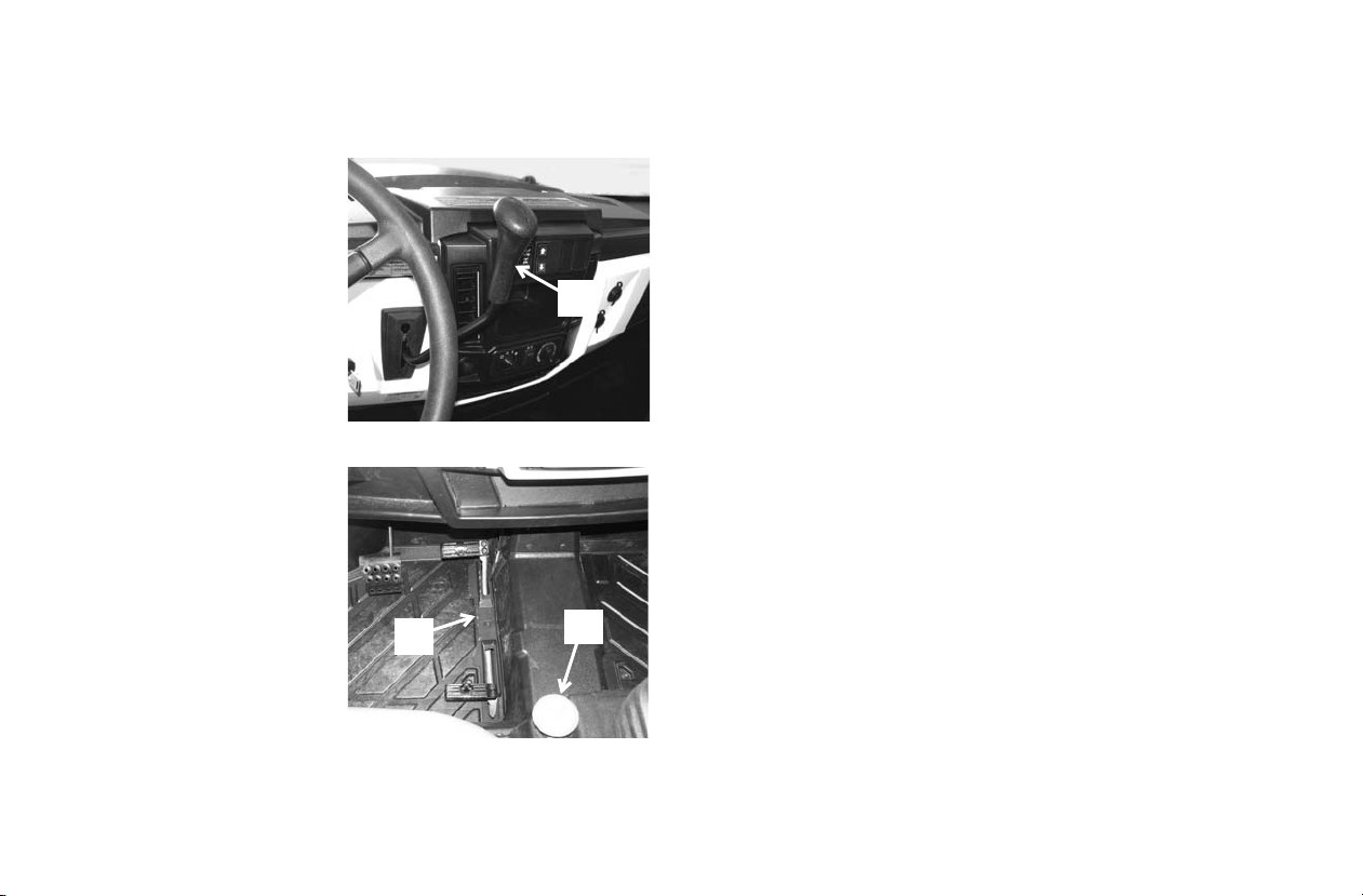
MAINTENANCE
1
2
3
Start Interlock System
Description
The utility vehicle is
equipped with a Start Interlock System. The following
must be in pla ce before the
Utility Vehicle can be star ted:
• The gear selector lever
must be in Park or Neutral
or the travel control pedal
must be in neutral.
• The PTO sw itch must be
OFF.
Inspecting
To check the function of the
Start Interloc k System, preform this pro cedure in an
open area on flat level
ground and make sure the
area is clear of bystanders.
1. With the gear selector
lever (Item 1) in low gear
and the PTO (Item 2)
OFF, move the travel
control pedal (Item 3) to
the forward travel
position, the engine must not start. Repeat the procedure
with the gear selector in High and moving the travel
control pedal into the reverse direction.
84
2. With the travel control pedal (Item 3) in neutral and the
gear selector lever (Item 1) in PARK, move t he PTO (Item
2) to the ON position, the engine must not start.
If the engine star ts in any of the se positions , see your dealer fo r
service.
PTO Interlock System (Model HDPTO)
Description
The utility vehicle is equipped with a PTO Interlock System.
The following must be in place before the PTO can be
engaged.
• The operator must be seated in the operators seat.
Inspecting
To check the funct ion of the PTO Interlock System;
1. With the operator in the operator seat, the gear selector lever in
PARK, the engine running and the PTO engaged; Raise up on
the operator’s seat (without exiting the utility vehicle) to take all
weight of the operator’s seat. The PTO system must disengage.
Monitor the dash panel to see that the PTO indicator turns OFF.
2. With the operator in the operator seat, the gear selector lever in
PARK, the engine running, raise off of the operator’s seat, then
activate the PTO system. The PTO must not engage.
If the PTO system does not function as described, stop using
the utility vehicle and see your dealer for service.
Page 86
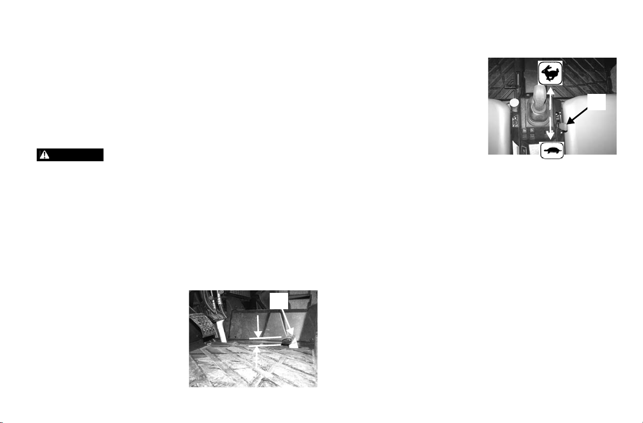
Travel Direction And Engine Speed Control
WARNING
1
2
System (Models HD And HDPTO Only
Description
The travel direction control system on models HD and HD
requires regular inspection. See information below.
Inspect the travel direction control and engine speed control
system to ensure proper operation. Incorrect adjustment may
cause erratic travel / engine speed conditions.
Avoid Serious Injury Or Death.
Failure to check or maintain proper operation of the travel control
system can result in an accident and lead to serious injury or death if
the travel control pedal or the engi ne speed cont rol lever st icks duri ng
operation. Always inspect the travel control pedal for free movement
and return to neutral before starting the engine and occasionally
during operation. Never s tart or op erate thi s vehic le if it has a stic king
or improperly o peratin g trav el c ontrol peda l. Im media tel y co nta ct y our
dealer for service if travel control problems arise.
Inspection And Maintenance (For BRUTUS HD
And HDPTO Models Only)
Position the utility vehicle on a
flat level surface. Put the gear
selector in PARK and stop the
engine. Exit the utility vehicle.
Check the travel control pedal
(Item 1) for excessive free play.
The correct amount of total free
travel on the trave l control peda l
PTO
MAINTENANCE
is 7,6 mm (0.30 in).
The engine speed control lever
(Item 2) will be used to control
engine RPM. When on flat level
ground, with the travel control
pedal in neutral, move the gear
selector lever to low and move
the engine speed control lever to
high idle. If any vehicle movement is detected, contact your
dealer for service.
When on flat level ground, the gear selector lever in Park,
press the travel control pedal to full forward, the engine speed
should be 3650 - 3750 RPM. Repeat with travel control pedal
fully in reverse, the engine speed should be 3650 - 3750 RPM
If the travel control pedal does not return to neutral unassisted
during normal operation, see your dealer for service.
Use the engine speed contr ol lev er (It em 2) an d ch eck the high
idle.
When on flat level ground, the gear selector lever in Park,
move the engine speed control lever (Item 2) to high idle. The
engine speed should be 3650 - 3750 RPM.
85
Page 87

MAINTENANCE
WARNING
Horse Power Management
Description
Horsepower management auto matica lly incr eases or decrease s
pressure to the hydrostatic transmission to sustain engine rpm
and maintain optimum drive performance.
Avoid Serious Injury Or Death.
• Always keep bystanders away from the work area and travel path.
• The operator must always look in the direction of travel.
Inspection and Maintenance
Test conditions: Air Conditioning off, n o weight in
cargo box, operator only.
no attachment, no significant electrical loads:
In a controlled area, free
of bystanders and on a
flat level hard surface.
Start the engine . See page
41. Operate the machine
until engine and hydraulics are at operating temperature. Move the gear
selector lever to high. T r aveling i n a stra ight path , acceler ate at
a high rate and monitor engine RPM. The engine RPM will
increase moderately and then increase quickly to approximately 3200 - 3700 RPM and maintain this RPM. If engine
speed does not meet this RPM range after 5 seconds of operation, contact your dealer for service.
If less responsive horsepower management is desired (i.e.:
increased engine luggi ng during opera tion), see your dealer for
adjustment.
Tip: Adjustments to the horsepower management systems are not
considered a defect and therefore are not a warrantable item.
86
Page 88

Engine Oil
-25° F
(-31° C)
+5° F
(-15° C)
+80° F
(+27° C)
+104° F
(+40° C)
SAE 15W-40
Synthetic 5W-40
SAE 10W-30
Safe
{
Safe
Range
Check Level
on Top Side
Dipstick
Add
Always check the oil level daily. Change the engine oil at the
intervals outl ined in th e Periodic Maintenance Chart begin ning
on page 78. Always change the oil filter whenever changing
oil.
WARNING! Vehicle operation with insufficient, deteriorated or
contaminated engine oil will cause accelerated wear and may result
in engine seizure, accident and injury. Always perform the
maintenance procedures as outlined in the Periodic Maintenance
Chart.
Oil Recommendations
NOTICE: Use of a non-recommended engine oil may cause serious
POLARIS recommends the use of POLARIS Diesel Oil (SAE
CI-4) for this vehicle. Always use the correct viscosity grade
based on the ambient temperature expected during operation.
See the chart below.
Oil Viscosity/Ambient Air Temperature Chart
engine damage.
MAINTENANCE
Oil Check
The oil dipstick is
located on the engine
under the passenger
seat.
Tip: Engine oil should be
checked cold or allo w
time for the oil to
drain back into pan
before checking to
prevent overfilling.
1. Position the vehicle
on a level surface.
2. Stop the engine.
3. Tilt the rear ca rgo
box to access the
engine oil dipstick.
4. Remove the dip-
stick. Wipe it dry
with a clean cloth.
5. Reinstall the dip-
stick, then remove
it and check the oil
level. Maintain the
oil level in the safe
range. Do not overfill.
Tip: Due to the dipstick entry angle into the crankcase, the oil level
will read higher on the bottom side of the dipstick. Always read
the level on the upper surface of the dipstick.
87
Page 89

MAINTENANCE
Oil Fill Cap
Engine Oil
Oil and Filter Change
Always change the oi l and filter at the int ervals outlined in the
Periodic Maintenance Chart beginning on page 78. Always
change the oil filter whenever changing oil.
1. Position the vehicle on a level surface.
2. Run the engine for two to three minutes until warm. Stop
the engine.
3. Clean the area around the drain plug.
4. Place a drain pan beneath the engine crankcase.
CAUTION! Hot oil can cause burns to skin. Do not allow hot oil to
contact skin.
5. Remove the drain plug. Allow the oil to drain completely.
6. Reinstall the sealing washer on the drain plug. The sealing
surfaces on drain plug and crankcase should be clean and
free of burrs, nicks or scratches.
7. Reinstall the drain plug. Torque to 25 ft. lbs. (34 Nm).
8. Place shop towels beneath the oil filter. Using an oil filter
wrench, turn the filter counter-clockwise to remove it.
9. Using a clean dry cloth, clean the filter sealing surface on
the crankcase.
10. Lubric ate the o-ring on the new filter with a film of fresh
engine oil. Check to make sur e the o-ring is in good co ndition.
11. Install the new filt er and turn by han d until the filt er gasket
contacts the sealing surface, then turn and additional 1/2
turn.
12. Remove the oil fill cap and add 2.75 quarts (2.6 l) of the
recommended oil.
13. Reinstall the oil
fill cap.
14. Shift the transmission to P ARK.
15. Apply the brakes.
16. Start the engine.
Allow it to id le
for one to two
minutes.
17. Stop the engine.
Inspect for leaks.
18. Allow time for
the oil to drain
back into the pan
before checking
to prevent overfilling the engine. Check the oil level on
the dipstick and add oil as necessary to bring the level to
the upper mark on the dipstick.
19. Dispose of used filter and oil properly.
88
Page 90
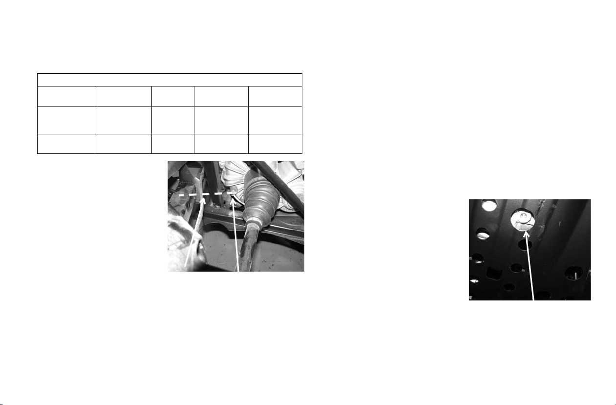
Gearcases
Fill Plug
Fill Level
Drain Plug
Gearcase Specification Chart
BRUTUS Gearcase Specific ation s
Gearcase Lubricant Capacity Fill Plug
Main Gearcase
(Transmission)
Front
Gearcase
AGL PLUS
Transmission
Fluid
Demand Drive
PLUS Fluid
41 oz.
(1200 ml)
6.75 oz.
(200 ml)
Torque
12 ft. lbs.
(16.3 Nm)
8-10 ft. lbs.
(11-13.6 Nm
Transmission (Main
Gearcase)
Always check and change t he
transmission oil at the intervals outlined in the Periodic
Maintenance Chart beginning on page 78. Maintain
the oil level even with the
bottom of the fill plug hole
threads.
Refer to the Gearcase Specifications Chart for recommended lubricants, capacities and torque specifications. See
page 128 for the part numbers of POLARIS products.
Drain Plug
Torque
12 ft. lbs.
(16.3 Nm)
8-10 ft. lbs.
(11-13.6 Nm)
MAINTENANCE
Oil Check
The fill plug is located on the right side of the transmission.
Access the fill plug from the rear right-hand side of the vehicle.
1. Position the vehicle on a level surface. Remove the fill
plug.
2. Check the oil level. Add the recommended oil as needed.
3. Reinstall the fill plug. Torque to specification.
Oil Change
The drain plug is located on the bottom of the transmission.
Access the drain plug from under the rear of the vehicle.
1. Remove the fill plug.
2. Place a drain pan under the
vehicle at the locat ion o f t he
drain plug.
3. Remove the drain plug.
Allow the oil to drain
completely.
4. Clean and reinstall the drain
plug with a new sealing
washer. Torque to specification.
5. Add the recommended oil.
6. Reinstall the fill plug. Torque to specification.
7. Check for leaks. Dispose of used oil properly.
89
Page 91
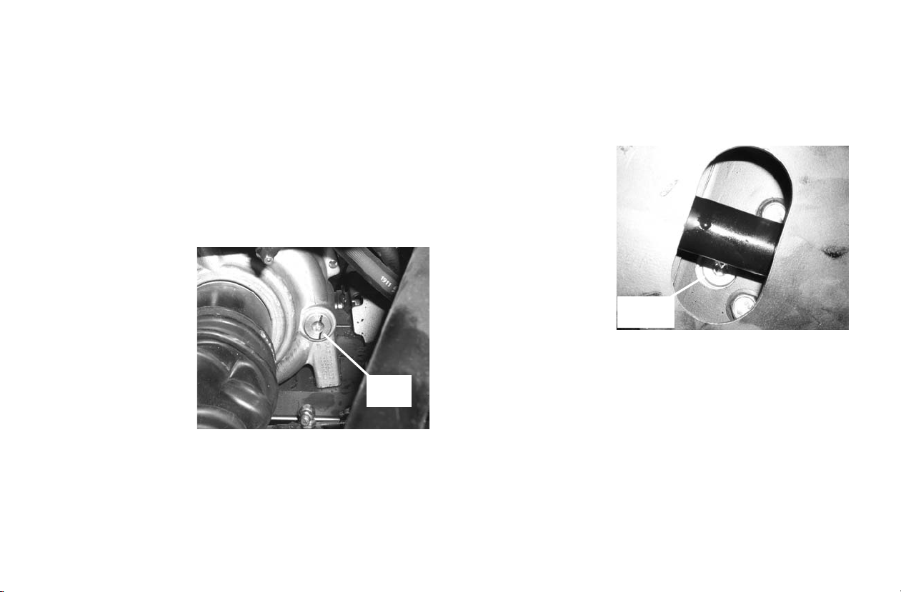
MAINTENANCE
Fill
Plug
Drain
Plug
Gearcases
Front Gearcase
Always check and ch ange the front ge arcase o il at the inte rvals
outlined in the Peri odi c Mai ntenance Chart beginning on pa ge
78. Maintain the oil level even with the bottom thread of the
fill plug hole.
Refer to the Gearcase Specifications Chart on page 89 for recommended lubricants, capacities and torque specifications.
See page 128 for the part numbers of POLARIS products.
Oil Check
The front gearcase fill
plug is located on the
right side of the front
gearcase.
1. Position the vehicle
on a level surface.
2. Remove the fill plug.
Check the oil level.
3. Add the recom-
mended oil as
needed.
4. Reinstall the fill plug. Torque to specification.
Oil Change
1. Support the vehicle securely on jack stands.
2. Remove the fill plug.
3. Place a drain pan
under the drain plug
on the bottom of the
gearcase.
4. Remove the drain
plug. Allow the oil to
drain completely.
5. Clean and reinstall
the drain plug.
Torque to specification.
6. Add the recommended oil.
7. Reinstall the fill plug. Torque to specification.
8. Check for leaks. Dispose of used oil properly.
90
Page 92

Cooling System
The engine coolant level is controlled or maintained by the
recovery system. The recovery system components are the
overflow bottle, radiator filler neck, radiator pressure cap and
connecting hose.
As coolant operating temperature increases, the expanding
(heated) ex cess coolant is forced out of the radiator, past the
pressure cap, and into the overflow bottle. As engine coolant
temperature decreases, the contracting (cooled) coolant is
drawn back up from the tank, past the pressure cap, and into
the radiato r.
Some coolant level drop on new vehicles is normal as the system is purging itself of trapped air. Observe coolant levels and
maintain as recommended by adding coolant to the overflow
bottle.
Adding or Changing Coolant
To ensure tha t the coolant maintains its ability to protect the
engine, we recommend that the system be completely drained
every two years and a fresh mixture of antifreeze and water
added.
NOTICE: Do not mix different types of coolant in the cooling system
when adding co olant. Mi xing type s can res ult in damage t o
the cooling sy stem.
POLARIS recommends the use of POLARIS Premium 60/40
anti-freeze/coolant or a 50/50 mixture of high quality aluminum compatible anti-freeze/coolant and distilled water.
POLARIS Premium 60/40 is already premixed and ready to
use. Do not dilute with water.
MAINTENANCE
Always follow the manufacturer's mixing recommendations
for the freeze protection required in your area.
Any time the cooling system h as been drained f or maint enance
or repair , r eplace the cool ant. If the recovery bottle has ru n dry,
the level in the radiator should be inspected. Add coolant as
needed.
Radiator and Cooling Fan
Always check and clean the screen and radiator fins at the
intervals outl ined in the Periodic M aintenance Chart beginn ing
on page 78. Do not obstruct or deflect air flow through the
radiator by installing unauthorized accessories in front of the
radiator or behind the cooling fan. Interference with the radiator air flow can lead to overheating and consequent engine
damage.
NOTICE: Washing the vehicle with a high-press ure hose could
damage the radiator fins and impair the radiator's
effectiveness. Using a high-pressure system is not
recommended.
91
Page 93

MAINTENANCE
Maximum
Minimum
Cooling System
Overflow Bottle Coolant Level
Always check and change the coolant at the intervals outlined
in the Periodic Maintenance Chart beginning on page 78.
Maintain the coolant level between the minimum and maximum marks on the bottle (when the fluid is cool).
The overflow bottle is
located under the hood.
1. Position the vehic le on
a level surf ace.
2. View the coolant level
in the overflow bottle.
3. If the coo lant level is
below the safe operating range, lift the hood
and locate the overflow bottle lid.
Remove the cap and the rubber vented plug and use a funnel to add coolant through the f il le r open ing . Reins ta ll the
rubber vented plug and the cap.
Tip: If coolant must be added ofte n, o r if th e o ver flow b ottl e ru ns com -
pletely dry, there may be a leak in the system. Have the cooling
system inspected by your POLARIS dealer.
Radiator Coolant Level
1. Lift the hood.
CAUTION! Escaping
steam can cause
burns. Never remove
the pressure cap while
the engine is warm or
hot. Always allow the
engine to cool before
removing the pressure
cap.
2. Slowly remove
the radiator
cap.
3. View the coolant level through the opening.
4. Use a funnel and slowly add coolant as needed.
Tip: This procedure is required only if the cooling system has been
drained for maintenance and/or repair. But if the overflow bottle
has run dry, the level in the radiator should also be inspected.
5. Reinstall the pressure cap. Use of a non-standard pressure
cap will not allow the recovery system to function properly. See your dealer for the correct replacement part.
92
Page 94

Vehicle Immersion
NOTICE: If your vehicle becomes immersed, major engine damage
can result if the mac hin e i s n ot th orou gh ly ins pe cte d. Take
the vehicle to your dealer before starting the engine.
If it's impossible to take your BRUTUS to a dealer before
starting it, follow the steps outlined below.
1. Move the vehicle to dry land or at the very least, to water
below the floorboards.
2. Drain water from the intake drain valve and thoroughly
dry the pre-filter box (l ocated at the left ROPS/OPS pos t) .
See page 95.
3. Dry any water that is present in the air cleaner housing.
Filter replacement is required if water is present.
4. Remove the air intake resonator box and drain any water
that is present. Dry the box thoroughly.
NOTICE: If you believe water has entered the engine, Do Not start
the engine. Engine damage will result. Take the vehicle to
your dealer before starting the engine.
5. Ta ke the vehicle to your dealer for service as soon as pos-
sible, whether you succeed in starting it or not.
6. Check the hydraulic fluid and differential fluid. If any
indication of moisture is present, replace the fluid and filters.
MAINTENANCE
93
Page 95

MAINTENANCE
Drain Valve Bleed Screw
Drain Hole
(viewed from bottom)
Tighten
Loosen
Fuel Filter/Water Separator
The fuel filter/water
separator is located
under the cargo box
on the left side of the
vehicle.
Inspect the separator
daily for leaks. Drain
water and replace the
separator at the intervals outlined in the
Periodic Maintenance Chart beginning on page 78.
Service the separator
more frequently if the vehicle is operated with poor qu ality
fuel.
CAUTION! Both fuel and water will drain from the separator during
the following procedure. Use caution and observe all fuel safety
precautions when handling fuel.
1. Raise the cargo box.
2. Place an appropriat e containe r under the fu el filte r drain to
catch fluids (water and fuel).
3. Slightly loosen the bleed screw to relieve fuel pressure in
the filter. Do not tighten the screw at this time.
4. Reach under the fuel filter and slightly loosen the drain
valve until the fluids drain from the drain hole. Do not
completely unscrew the drain valve.
94
5. When fluids stop draining from the valve,
tighten the valve firmly
(by hand only). Tighten
the bleed screw.
6. With the gear selector in
Park, turn the key to the
ON position. Do Not start
the engine.
7. The fuel pump will start
pumping fuel with the key
in the ON position (10 -15
seconds) and will force
air out of the fuel system.
8. At times it may be necessary to open the bleed screw on
the fuel filter housing until fuel comes from the valve with
no air bubbles.
9. Clean up any spilled fuel and soiled shop towels properly.
10. Start the engine and check for fuel leaks.
11. Lower the cargo box.
Page 96
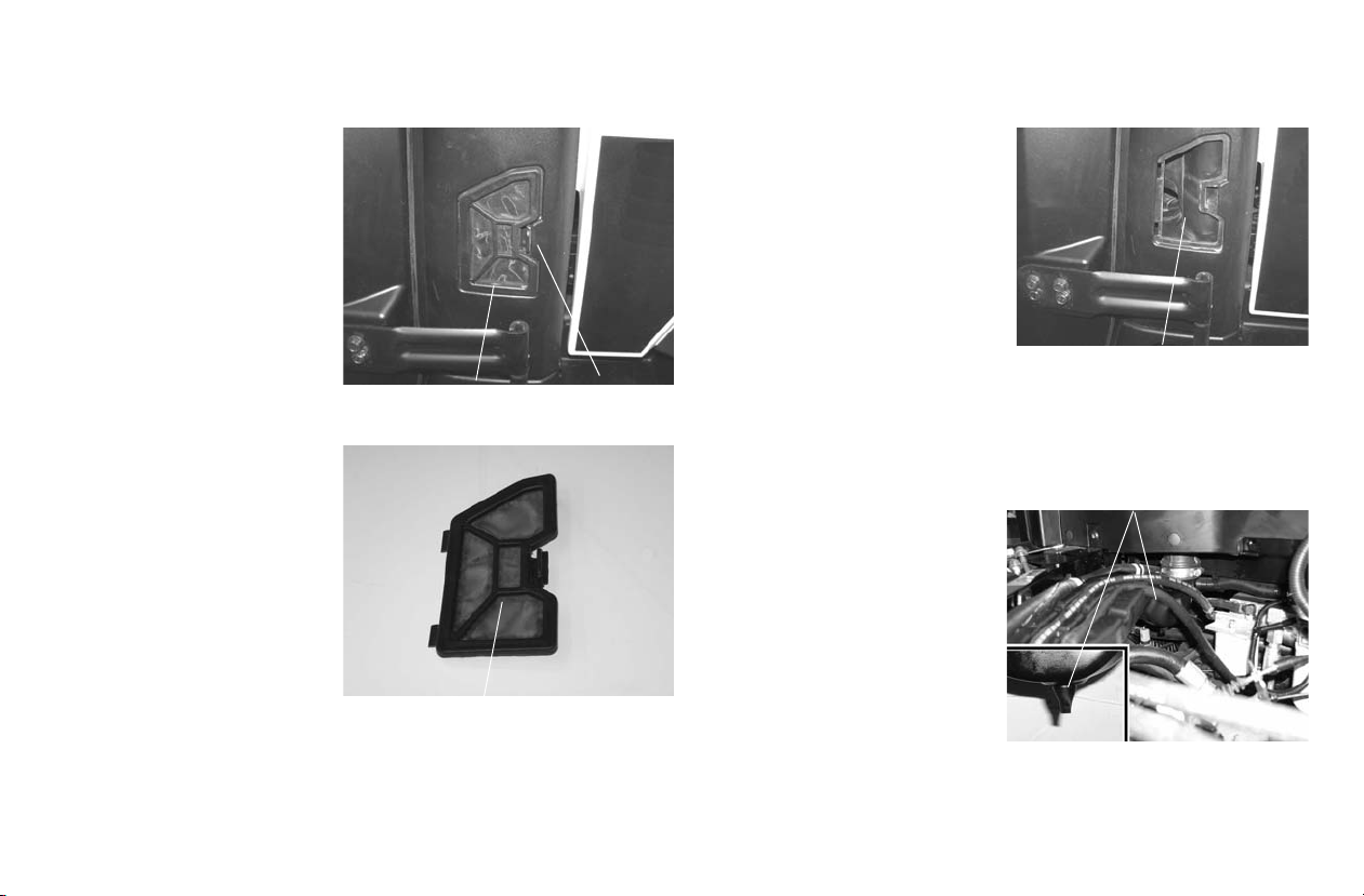
Air Pre-Filter
Pre-Filter
Pre-Filter
Latch
Pre-Filter Housing
Water Drain Valve
Always clean the pr e-filter
at the intervals out lined in
the Periodic Maintenance
Chart beginning on page
78. Service the pre-filter
more frequently if the
vehicle is operated in wet
or dusty conditions or at
high engine RPM for
extended periods.
The intake air pre-filter is
located in the access pa nel
on the left rear ROPS /
OPS post. The pre-filter
traps larger particles
before the air reaches the
main engine air filter.
Removal
1. Press the latch
towards the front of
the vehicle to remove
the prefilter.
2. Clean debris from the
pre-filter and inspect
for damage. If any
damage is found, replace the pre-filter assembly.
MAINTENANCE
3. DO NOT use compressed
air to clean the pre-filter
open. Use a damp cloth
and clean the inside of the
pre-filter opening.
Installation
1. Insert the two tabs on the
pre-filter assembly into
the side frame. Rotate the
pre-filter into the frame
and make sure the latch
securely retains the pre-filter to it’s o riginal location.
Cleaning Intake Water Drain Valve
1. Raise the cargo box.
2. An air intake water drain
valve is lo cated below
the pre-filter that should
be inspected and c lean a t
the same tim e the pre-filter is cleaned.
3. Remove dirt and debris
from the valve and
squeeze the valve to
make sure it is not
plugged. If any damage
is found, replace the drain valve.
95
Page 97
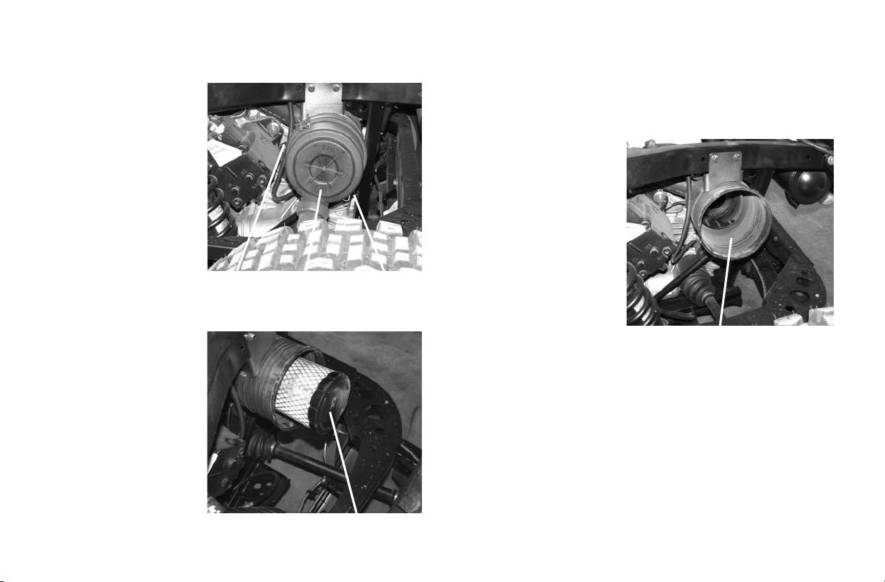
MAINTENANCE
Clip
Clip
Cover
Filter
Clean Air Box
Air Filter
Always chan ge the air filter at the int ervals outlined in the Periodic
Maintenance Chart beginning on page 78. Service
the air filte r more frequently if the vehicle is
operated in wet or dusty
conditions or at high
engine RPM for extended
periods.
1. Lift the cargo box to
access the air box.
2. Release the two air
box cover clips. Remove the air box cover.
3. Remove the air filter
assembly with a pulling and twisting
motion. Use care to
avoid damaging the
filter element.
NOTICE: Operating a diesel engine with a soiled or damaged air
filter can result in engine damage. Do not attempt to wash
the filter. Always replace a soiled or damaged filter with a
new filter.
4. Clean any dirt or
deposits from the air
box.
5. Reinstall the filter into
the air box. Make sure
it fits tightly.
6. Install the cover and
secure the with the two
clips.
96
Page 98
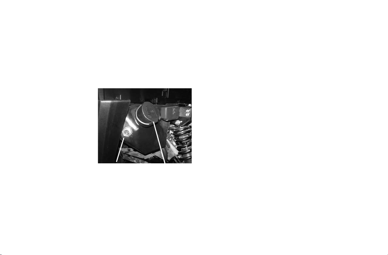
Hydraulic/Hydrostatic System
Sight Gauge Fill Cap
Checking Fluid
WARNING!
Avoid Injury Or Death.
Always clean up spilled fuel or oil. Keep heat, flames, sparks or
lighted tobacco away from fuel and oil. Failure to use care around
combustibles can cause explosion or fire.
Use only recommended fluid in the hydraulic system.
Park the utility vehicle on
a flat level surface, lower
the attachment arm and
put the attachment flat on
the ground. See page 44.
Move the gear selector
lever to Park , stop the
engine and exit the utility
vehicle. See page 41.
Raise the cargo box. See
page 62.
Check the fluid level in
the sight gauge. The fluid
level is correct when at
the center of the sight gauge.
Use only recommended Polari s hydraul ic fluid when addi ng or
changing the hydraulic fluid. See page 128.
MAINTENANCE
Adding Fluid
Clean the area around the fill cap.
If needed, remove the fill/breather cap and add fluid.
Lower the cargo box. See page 62.
97
Page 99
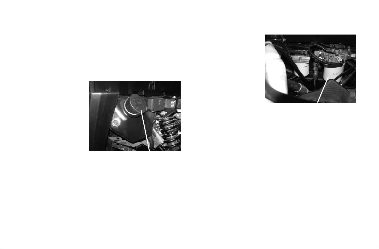
MAINTENANCE
Fill/Breather Cap
Hydraulic/Hydrostatic Filter
Hydraulic/Hydrostat ic System
Removing And Replacing Hydraulic/Hydrostatic
Filter
Change the hydraulic/ hydrostati c filter at t he intervals outlined
in the Periodic Maintenance Chart beginning on page 78.
Park the utility vehicle on a flat level surface, lower the attachment arm and put the attachment flat on the ground.
Move the gear selector
lever to Park , stop the
engine and exit the utility
vehicle. See page 41.
Raise the cargo box. See
page 62.
Replace the fluid if it
becomes contaminated or
after major repair.
Thoroughly clean the area
around the fill cap.
Loosen the fill / breather
cap to relieve hydraulic system pressure.
WARNING!
Avoid Injury Or Death
Diesel fuel or hydraulic fluid under pressure can penetrate skin or
eyes, causing seriou s injury or dea th. Fluid lea ks under pressu re may
not be visible. Use a pi ece of cardboard or wood to fin d le aks . Do n ot
use your bare hand. Wear s afe ty go ggles. If fluid enters skin or eye s,
get immediate medical attention from a physician familiar with this
injury.
Place a container under
the filter. Recycle or d ispose of used oil in an
environmentally safe
manner.
Remove the hydraulic filter.
Clean the surface of the
filter housing where the
filter contacts the housing.
Put clean oil on the seal
of the new filter. Install and hand tighten.
Tighten the fill / breather cap.
Recycle or dispose of used fluid in an environmentally safe
manner.
WARNING!
Avoid Injury Or Death
Always clean up spilled fuel or oil. Keep heat, flames, sparks or
lighted tobacco away from fuel and oil. Failure to use care around
combustibles can cause explosion or fire.
Lower the cargo box. See page 62.
Start the engine and operate the hydraulic controls. Stop the
engine and check for leaks.
Check fluid level and add as needed. See page 97.
Use only recommended fluid in the hydrauli c system. See page
128.
98
Page 100
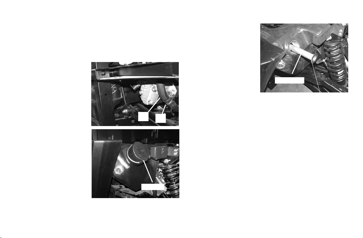
Hydraulic/Hydrostatic System
2
1
Fill Cap
Fill Screen
Removing And Replacing Hydraulic/Hydrostatic
Fluid
Change the hydrauli c/hydrostat ic flui d at the i nterval s outline d
in the Periodic Maintenance Chart beginning on page 78.
Replace the fluid if it
becomes contaminated or
after major repair.
Always replace the
hydraulic / hydrostatic filters whenever the hydraulic fluid is replaced.
Move the gear selector
lever to Park and stop the
engine. See page 41.
Raise the cargo box.See
page 62.
Remove the clamp (Item
1) and the hose (Item 2)
from the gear pump fitting
and drain the hydraulic
fluid into a container.
Thoroughly clean the ar ea
around the fill cap.
Slowly loos en the fill /
breather ca p to relieve
hydraulic system pressure in the tank. Remove the fill /
breather cap.
MAINTENANCE
Remove and clean the
hydraulic fill screen. Use
low air pressure to clean
the screen.
Remove the hydraulic filter. see page 98. Install a
new filter.
Dispose of the used fluid
in an environmentally safe
manner.
Install the fill screen and
fill to the proper level. See
Page 99.
Install and tighten the fill / breather cap.
Lower the cargo box. See page 62.
WARNING!
Avoid Injury Or Death
Always clean up spilled fuel or oil. Keep heat, flames, sparks or
lighted tobacco away from fuel and oil. Failure to use care around
combustibles can cause explosion or fire.
Start the engine and operate the hydraulic controls. If any
hydraulic function operation is not smooth, this may indicate
that air is trapped i n th e hyd raulic system. Continue to operate
all the hydraulic functions until operation is smooth.
Stop the engine and check for leaks.
Check fluid level and add as needed.
99
 Loading...