

Page 1

OWNER’S MANUAL SUPPLEMENT
C
P
C
I
I
R
V
E
S
Y
T
R
1999 XPLORER 400
PN 9914907
IMPORTANT: This is a supplement to your owner’s manual. This information should remain with your owner’s
manual at all times.
Specifications
Xplorer 400
Body Style Gen IV
Gross Vehicle Weight 1100
Fuel Capacity 4 U.S. Gallons
Gearcase Oil 16 Ounces
Injector Oil Capacity 2 Quarts
Front Rack
A
(Maximum - Capacity)
P
A
Rear Rack 180 Lbs.
Tongue Weight 30 Lbs.
I
T
Tow H it ch Std
Tow Capacity 850 Lbs.
E
S
Turn Radius 65²
Ground Clearance 7.5²
Height 47.5²
Length 81²
Seat Height 34²
Weight 588
Wheel Base 49.75²
Width 46²
Drive System Type PVT
D
Shift Type Side Lever (Hi/Low-N-R)
R
I
Gear Reduction - Low 6.14/1
Gear Reduction - Reverse 4.74/1
E
Gear Reduction - Forward 3.6/1
Front Drive (ratio) 2:1
Y
S
Final Drive (ratio) 13/36 78P
Center Drive (ratio) Not Applicable
E
M
Drive Chain 520 O-Ring
T
Front Tire 25 x 8-12
I
Rear Tire 25 x 11-10
R
E
Tire Pressure (front) 4
S
Tire Pressure (rear) 3
90 Lbs.
1
Page 2

Xplorer 400
S
K
K
N
G
N
&
O
I
G
T
Front Susp. - Mac Strut 6.25
S
Rear Susp. - Progressive
U
Rate Swing Arm
S
P
Shock Adjustment CAM
Front Brake Fixed disc, hydraulic floating
B
R
Rear Brake Hydraulic, opposed piston cal-
A
ESAuxiliary Brake Hydraulic, opposed piston cal-
Park Brake Hydraulic lock, all wheel
Engine Model Number EC38PLE-09
Engine Type 2 Cycle, Single Cylinder
Lubrication Oil Injection
Bore x Stroke 83 x 70
E
Displacement 378
Compression Ratio 6.9:1 Effective
G
I
Engine Cooling Liquid
Alternator Output (watts) 200
E
Carburetion 1/VM34SS
Main Jet 210
C
Pilot Jet 35
Needle Jet 0-6 (480)
O
L
Cutaway 1.5 Nickel / Aluminum
I
Air Screw 1.5 Turn
N
G
Jet Needle 6CEY6-3
Ignition CDI
Timing 23.5 @ 3000
Spark Plug Gap .7mm / .028
Spark Plug Type NGKBR8ES
Exhaust USFS Approval Pending
L
Headlight (handlebar) 1 single beam, 60 watts
I
Headlight (grill) 2 single beam, 27 watts
G
H
Taillight (watts) 8.26
Brake Light (watts) 26.9
S
8.9
caliper
iper, rear axle fixed disc
iper, rear axle fixed disc
2
Page 3
Xplorer 400
F
T
E
3-Point Hitch Accessory
Battery 12V 14 AH
DC Plug In - Rear Standard
DC Socket - Forward Accessory
F
E
Electric Start Standard
A
High Beam Indicator Standard
T
U
High Temp Indicator Standard
R
Windshield Accessory
E
S
Low Oil Light Standard
Neutral Indicator Standard
Reverse Indicator Standard
Speedometer Standard
Tool Kit Standard
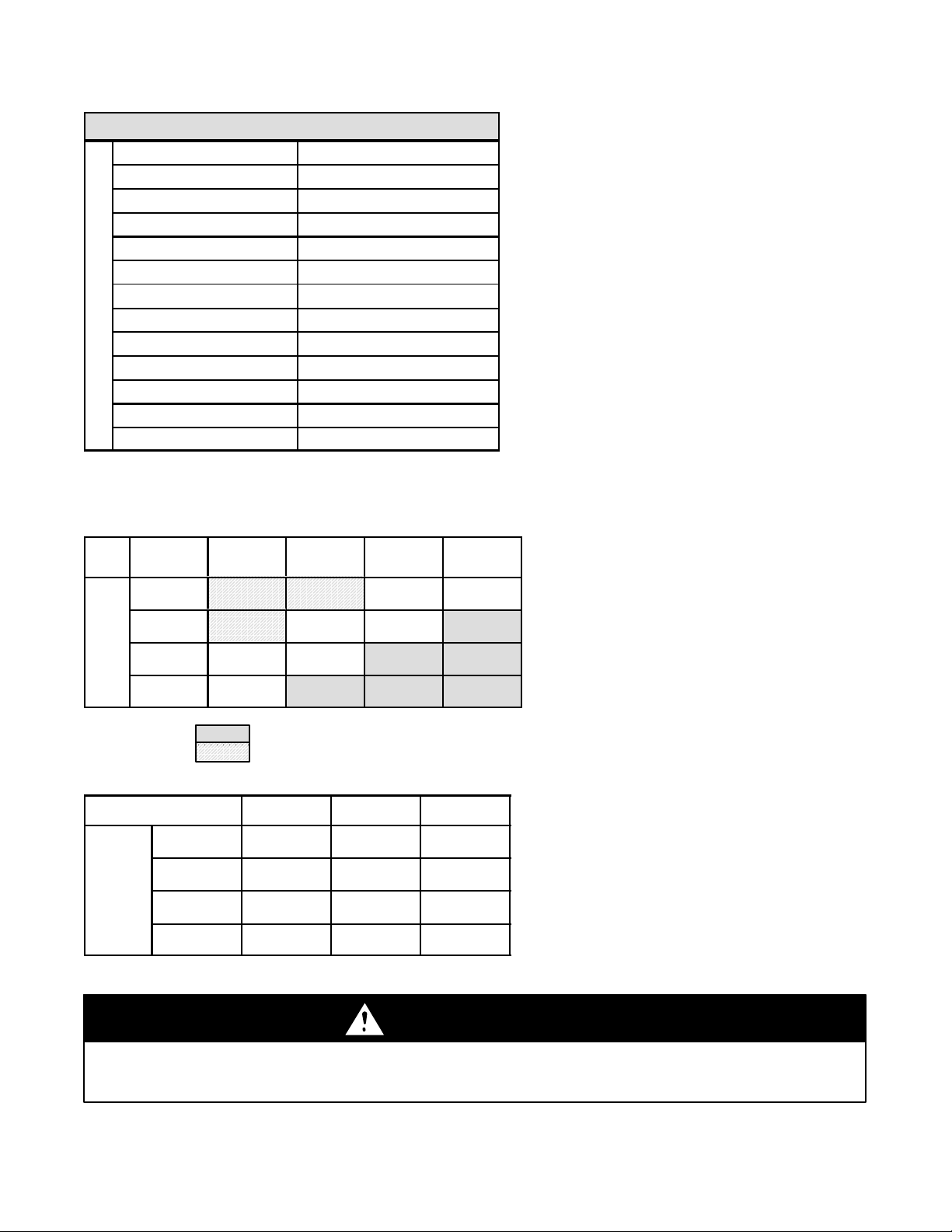
1999 Xplorer 400
(Engine - EC-38PLE-08)
Carburetor Jetting
Altitude Ambient
Meters
(Feet)
Temperature
0-900
(0-3000)
900-1800
(3000-6000)
1800-2700
(6000-9000)
2700-3700
(9000-12000)
Below 0°F
(Below --18°C)
227.5 217.5 210 202.5
217.5 210 202.5 192.5
207.5 200 192.5 185
197.5 190 182.5 175
Clutching
Altitude Shift
Meters
(Feet)
0-900
(0-3000)
900-1800
(3000-6000)
1800-2700
(6000-9000)
2700-3700
(9000-12000)
0° to 40°F
(--18°Cto
+5°C)
+40° to +80°F
(+5°Cto
+26°C)
+80°F&Above
(+26°C&
Above)
- Drop Needle one position (raise E-Clip)
-TurnAirScrewin1/2to3/4turn
Weight
S55 Blue / Green 2-2
S Blue / Green 2-2 or 2-1
s Blue / Green 2-1
s Blue / Green 2-1
Clutch
Spring
Driven
Helix
ATTENTION
Do not wash the electronic speedometer with a high pressure washer. Wash the unit by hand or with a garden
hose. High water pressure may allow water to enter the speedometer and cause damage to the electronic
components.
3
Page 4

Speedometer
Your Polaris ATV is equipped with a new electronic speedometer which senses vehicle speed from the right hand front
wheel. The electronic speedometer measures distance in miles and kilometers as well as hours of operation. To
display each mode, press the button on the face of the speedometer once to “toggle” through the functions. Each
function will be displayed as shown:
Miles / Kilometers 00000.0
Trip Miles / Kilometers 000.0
Hours 00000.0
To reset Trip Miles / Kilometers:
1. Toggle to Trip Miles / Kilometers.
2. Hold down button approximately 4 seconds.
To change distance measurement from Miles to Kilometers or vice versa:
1. Toggle to odometer.
2. Hold down the button approximately 8 seconds until the word FARIA appears in the display, then release the
button. If the last digit in the display is a “K”, the measurement is Kilometers, if the last digit is an “M”, the
measurement is Miles.
The speedometer also includes a reverse speed limit function that limits the ATVs speed in reverse after approximately 7 to 9 mph. Refer to your ATV Owner’s Manual Supplement for more information.
The following information (page 35) of your ATV Owner’s Manual, has been revised.
Engine Electrical Switches
1. Override Switch (Reverse Speed Limit-
er) - This vehicle is equipped with a reverse
speed limiter system. To obtain additional
power while backing up, depress the override button. WARNING: Never activate the
override button while throttle is open as loss
of control may result, causing severe personal injury or death.
NOTE: The override switch also allows activation of Demand 4 Drive (All Wheel Drive)
in reverse, if Demand 4 Drive switch is on.
2. Main Switch - This switch must be turned
clockwise to the “on” position to start the engine.
3. Emergency Engine Stop Switch -The
engine will not start or run when the switch is
in its “off” position. Its purpose is to provide
the operator with a quick means of engine
shutdown in case of stuck throttle or other
emergency.
NOTE: Both the main switch and the emergency engine stop switch shut off all electrical power to the entire vehicle including
lights.
4. Engine Start Button - Slide the stop switch to the center “run” position and push up to start.
3
1
4
WARNING
Backing your ATV can be dangerous!
You could hit an obstacle or person behind you; or the vehicle could tip
over rearward on a s teep incline causing severe injury or death.
Always back slowly avoidingexcessive speed anddo notuse the reverse
speed override switch system unless additionalpower is required for vehicle movement.
Avoid backing on steep inclines.
Avoid turning at sharp angles in reverse.
2
4
Page 5

The following Throttle Lever information, taken from page 38 of your ATV Owner’s Manual, has been revised.
CONTROL AND PARTS FUNCTIONS
Engine Throttle and Choke
Throttle Lever
Engine speed and vehicle movement are controlled by pressing the throttle lever. The throttle system is spring loaded and engine speed returns to idle when
the lever is released. This vehicle is equipped with a Polaris Electronic Throttle
Control (ETC) which is designed to reduce the risk of a frozen or stuck throttle.
In the event the throttle cable should stick in an open position, the engine will stop
and power to the rear wheels will cease when the operator releases the throttle
lever.
Choke Lever
Refer to the engine starting procedure on page 56 for correct choke and throttle
settings during starting.
Choke
Throttle
WARNING
The Electronic Throttle Control (ETC) stops the engine in the event of a throttle system malfunction and is
provided for your safety. Do not attempt to modify the ETC system or replace it with any after market throttle
mechanisms.
WARNING
Do not start or operate an ATV with sticking or improperly operating throttle controls. A stuck or improperly
operating throttle could cause an accident resulting in severe injury or death.
Always contact your dealer for service repairs whenever throttle problems arise.
Failure to check or maintain proper operation of the throttle system can result in the throttle lever sticking
during riding and cause an accident.
Always check the lever for free movement and return before starting the engine and occasionally during rid-
ing.
Throttle Cable Free Play Adjustment
Throttle cable free play is adjusted at the handlebar.
1. Slide the boots off inline cable adjuster sleeve. Loosen adjuster locknut.
2. Turn adjuster sleeve until 1/16² to 1/8² freeplay is achieved at thumb lever.
3. Tighten locknut and slide boots over cable adjuster until they touch at the middle point of adjuster.
Boot
Adjuster
Sleeve
Locknut
Boot
5
Page 6

Exclusive Demand 4 Drive System (All Wheel Drive)
This Polaris AWD is equipped with a unique,
Polaris exclusive, Demand 4 Drive (AWD)
system which is activated by a switch on the
right handlebar. When the switch is “off” the
4x4 is in 2 wheel drive at all times. When the
switch is “on” the 4x4 is in Demand 4 Driveand
the front wheels will automatically engage
anytime the rear wheels lose traction. When
the rear wheels regain traction, the front
wheels will automatically disengage. NOTE:
The override switch also allows activation of
Demand 4 Drive (AWD) in reverse, if Demand
4 Drive switch is on.
There is no limit to the length of time the vehicle may remain in Demand 4 Drive.
The Demand 4 Drive switch may be turned on or off while the vehicle is moving. If the switch is turned off when the front hubs are
driving they will not release until the rear wheels regain traction.
CAUTION: Do not switch on Demand4 Drive if the rear wheels are spinning. This maycause severedrive shaftand clutch damage.
Engage the Demand 4 Drive switch before getting into conditions where front wheel drive may be needed. If the rear wheels are
spinning, release the throttle before turning the Demand 4 Drive switch on.
AWD Switch
The following
Oil Pump Adjustment Procedure, taken from page 106 of your ATV Owner’s Manual, has been revised.
Oil Pump Adjustment Procedure
400 Engines
1. Before adjusting the oil pump, check engine idle RPM and carburetor adjustments
which are found in the owner’s manual supplement.
2. Loosen throttle cable jam nut and turn adjuster in or out until there is 1/16² -1/8² (.16
- .32 cm) of throttle lever travel before throttleslide starts to open. See Owner’s Manual
Supplement.
3. Place very slight pressure on the throttle leveruntil all freeplay is removed fromthrottle
cable (to the point where the carb slide is just starting to rise).
4. Lift boot up off adjuster sleeve. Remove the oil pump cover. Loosen the cable adjuster
locknut. Adjust oil pump cable until marks align (D) when the throttle slide just begins
to raise.
5. Tighten the locknut.
6. Recheck adjustment. If correct, slide boot all the way down over the upper portion of the bottom nut to ensure good sealing
against water entry. Reinstall oil pump cover and gasket.
Boot
Adjuster
Sleeve
Upper Portion
of Bottom Nut
Oil Pump Adjustment 400
D
PN 9914907 Rev 03 12/98
Printed in U.S.A.
6
Page 7

7
 Loading...