

Page 1

1
ALPHA RTK RECEIVER
USER GUIDE
Version 0.8
October 25, 2018
info@polaris-gnss.com
https://www.polaris-gnss.com
Page 2

2
Table of Contents
1. Overview ................................................................................................................ 3
1-1 Introduction ..................................................................................................... 3
1-2 RTK Operation Guidelines ................................................................................ 3
1-3 Alpha RTK Receiver Features……………………………………………………………………….4
2. Applications ............................................................................................................ 5
3. Description of Interfaces ........................................................................................ 6
3-1 Appearance ...................................................................................................... 6
3-2 Pinout of 6-Pin Connector ............................................................................... 7
3-3 Pinout of 4-Pin Connector ............................................................................... 7
3-4 Connector Cables for Alpha ............................................................................. 8
4. Application Scenarios ........................................................................................... 10
4-1 Special Short Baseline Experimental Setup ................................................... 10
4-2 RTK Survey and Data Collection ..................................................................... 11
4-3 Real-Time Precision Guidance ....................................................................... 13
4-4 Hardware Configuration Settings ................................................................... 16
5. Preparing for First Time Use ................................................................................ 17
5-1 RTK Viewer ..................................................................................................... 17
5-2 USB Driver ...................................................................................................... 17
5-3 Checking Alpha Receives Satellite Signal ....................................................... 17
6. RTK Setup ............................................................................................................. 19
6-1 Introduction ................................................................................................... 19
6-2 Configuring the Rover .................................................................................... 20
6-3 Configuring the Base ...................................................................................... 21
6-4 RTK Application Scenarios In Detail ............................................................... 25
7. Configure RTK License .......................................................................................... 41
8. Raw Measurement Recording and Post Processing ............................................. 42
9. Software Update .................................................................................................. 43
APPENDIX
A-1. Additional Software Configurations ..................................................................... 46
A-2. NTRIP Server/Caster Setup for Users Without Fixed IP ..................................... 48
A-3. NTRIP Server/Caster Setup for Users With Fixed IP ........................................... 51
A-4. Data Flow of the I/O Interface ........................................................................... 54
Page 3

3
1. Overview
1-1 Introduction
Alpha is a high performance RTK receiver with multiple interfaces, including UART, USB, and Bluetooth.
It offers centimeter-level positioning accuracy suitable for survey, mapping, GIS data collection, and
outdoors robotic precision guidance.
By default, Alpha is shipped as RTK rover to accept RTCM3.x message or SkyTraq carrier phase raw
measurement data from a RTK base, and provide centimeter-level accurate position result relative to
the RTK base in standard NMEA message format. Alpha can also be configured as a RTK base to
provide RTCM3.x message or SkyTraq carrier phase raw measurement data output.
Alpha has three major interfaces for different applications. The USB interface is mainly used for
configuration, monitoring, and supplying power. With Bluetooth V2.1+EDR module built-in, Alpha can
be used as external Bluetooth RTK receiver for Android Mobile Device to provide higher accuracy
positioning than internal GPS. The 3.3V LV -TTL UART interface allows simple connection to controllers
for precision guidance applications, replacing normal meter-level accuracy GPS receiver.
Alpha can easily connect and use with Pixhawk / ArduPilot using the supplied connector cable,
enabling UAV to navigate with centimeter-level position accuracy. Unique to Alpha is camera shutter
triggered RTK position stamp function, which is much more accurate than alternative time stamp
based linear interpolation approach to re-generate camera triggered position for aerial survey
application.
1-2 RTK Operation Guidelines
To provide centimeter-level RTK accuracy, Alpha requires much better operating condition than
conventional meter-level accuracy GPS receiver:
Baseline distance between base and rover should be under 10Km.
Open sky environment without interference and signal blockage
Received signal level should be no less than 40dB/Hz.
12 or more satellites over 15 degree elevation angle
Good satellite geometry with satellites spread over four quadrants of the sky.
Page 4

4
1-3 Alpha RTK Receiver Features
Base or Rover Mode Configurable Using RTK Viewer Utility
Supports L1 GPS/GLONASS or L1 GPS + B1 BDS RTK Operation
Supports LV-TTL UART / USB / Bluetooth V2.1+EDR Interface
Supports SDHC micro-SD Card for Data Logging Post Processing
RTK Position Accuracy 1cm + 1ppm
Maximum RTK Update Rate 10Hz
Supports RTCM 2.x / 3.x Messages
NMEA Output
Update Rates:1 / 2 / 4 / 5 / 8 / 10 Hz for RMC / GGA / VTG / PSTI-030
Messages:GGA / GLL / GSA / GSV / RMC / VTG / ZDA / PSTI
Baud Rate
Bluetooth:115200
UART / USB:4800 / 9600 / 19200 / 38400 / 57600 / 115200, default 115200
Current Consumption
180mA @ 5V
Weight:40 g
Page 5
5
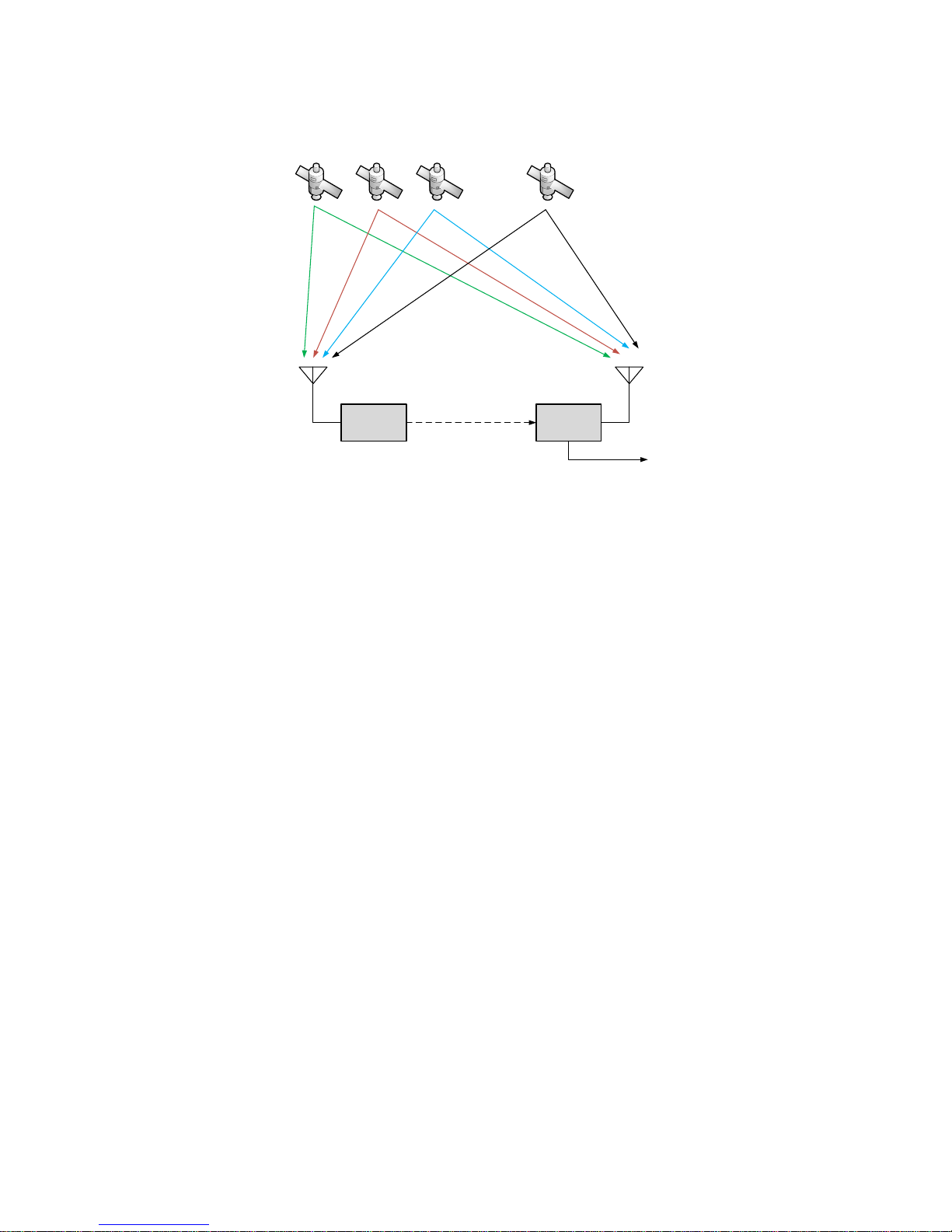
2. Applications
Alpha RTK
Base
RTK
antenna
Alpha RTK
Rover
RTK
antenna
. . .
RTCM3.x / RAW
NMEA
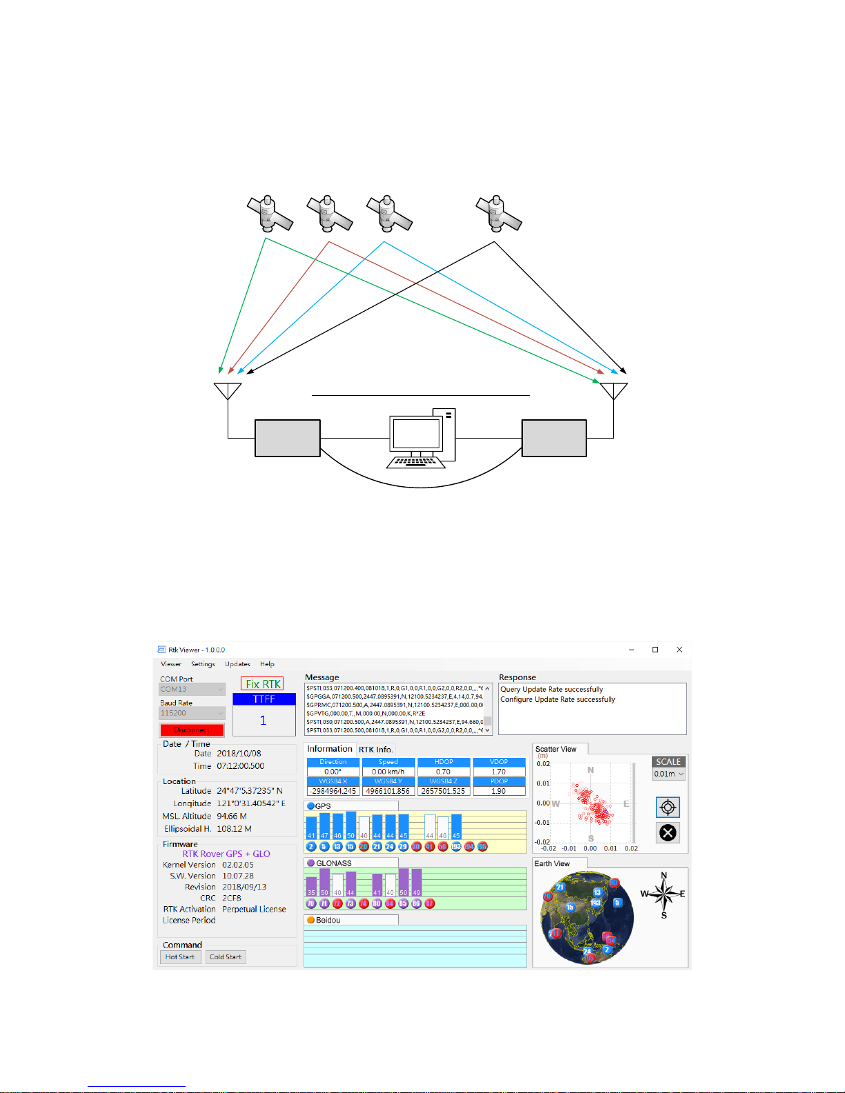
Figure 2-1
Alpha RTK rover works with carrier phase measurement, using fractional part of ~19 centimeter wave
length GNSS signals and differential principles to achieve centimeter-level accuracy positioning with
respect to the RTK base.
Referring to figure 2-1, Alpha RTK base antenna is set at a fixed location, with antenna location
coordinates already a known reference, or surveyed by method described in later section. It receives
signals from GPS/GLONASS or GPS/BDS satellites, generates correction data in RTCM3.x or SkyTraq
raw measurement format, and sends it to remote Alpha RTK rover through wireless channel. The rover
uses this correction data along with signals received from satellites to calculate the precise position of
the RTK rover antenna, and output antenna position / velocity / time information in NMEA-0183
format. Correction data from the one RTK base can be sent to an unlimited number of RTK rovers.
The Alpha RTK receiver is suitable for, but not limited to, following applications:
Surveying and GIS data collection with Android mobile device
Precision farming machine guidance
Precision grass cutting machine guidance
Precision guidance of unmanned aerial vehicles (UAV)
Aerial survey RTK position stamping without need of ground control points
Precision tracking of vehicle dynamics
Page 6
6
3. Description of Interfaces
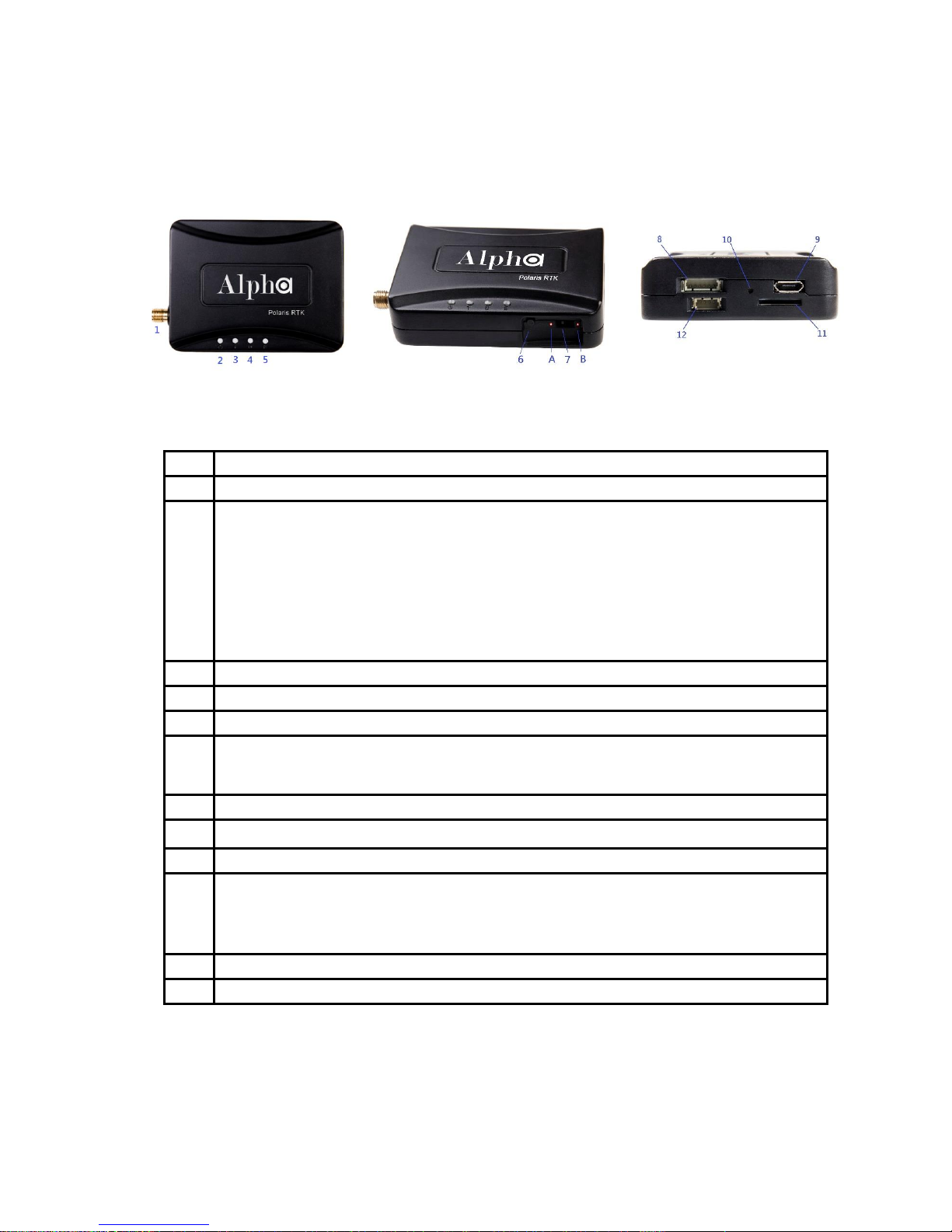
3-1 Appearance
Figure 3-1
No.
Description
1
SMA connector for RTK antenna.
2
Status LED. There are three states shown for Alpha as Rover
1. Base data not received: flashes two times followed by 1 sec of silence.
2. In process of finding RTK solution: flashes with frequency at 1Hz or 4 Hz depends on the RTK
ratio is in between 1 and 3 or in between 3 and 5.
3. RTK solution found: remain lighted continuously.
This LED is always off when Alpha is configured as Base.
3
LED for indicating the TTL UART interface is selected.
4
LED for indicating the USB interface is selected.
5
LED for indicating the Bluetooth interface is selected.
6
Push button for interface selection. Each time the button is clicked, the selected interface toggles.
Press this button for more than 3 seconds will enable/stop logging measurement data to SD Card.
7
Slide switch for choosing the operating mode, see section 4-4 for details.
8
6-pin TTL connector for Base-to-Rover or Rover-to-UAV applications, see section 3-2 for details.
9
Micro USB connector
10
SD card status LED. When the SD card is inserted, this LED will flash and record raw measurement
data to the SD card, until number of files on the SD card reaches 129. In this case the LED lights up
continuously, and recording stops. If no SD card is inserted, the LED is off.
11
Micro SD card connector for raw measurement data recording.
12
4-pin TTL connector for aerial survey applications. See section 3-3 for details.
Table 3-1
Page 7
7
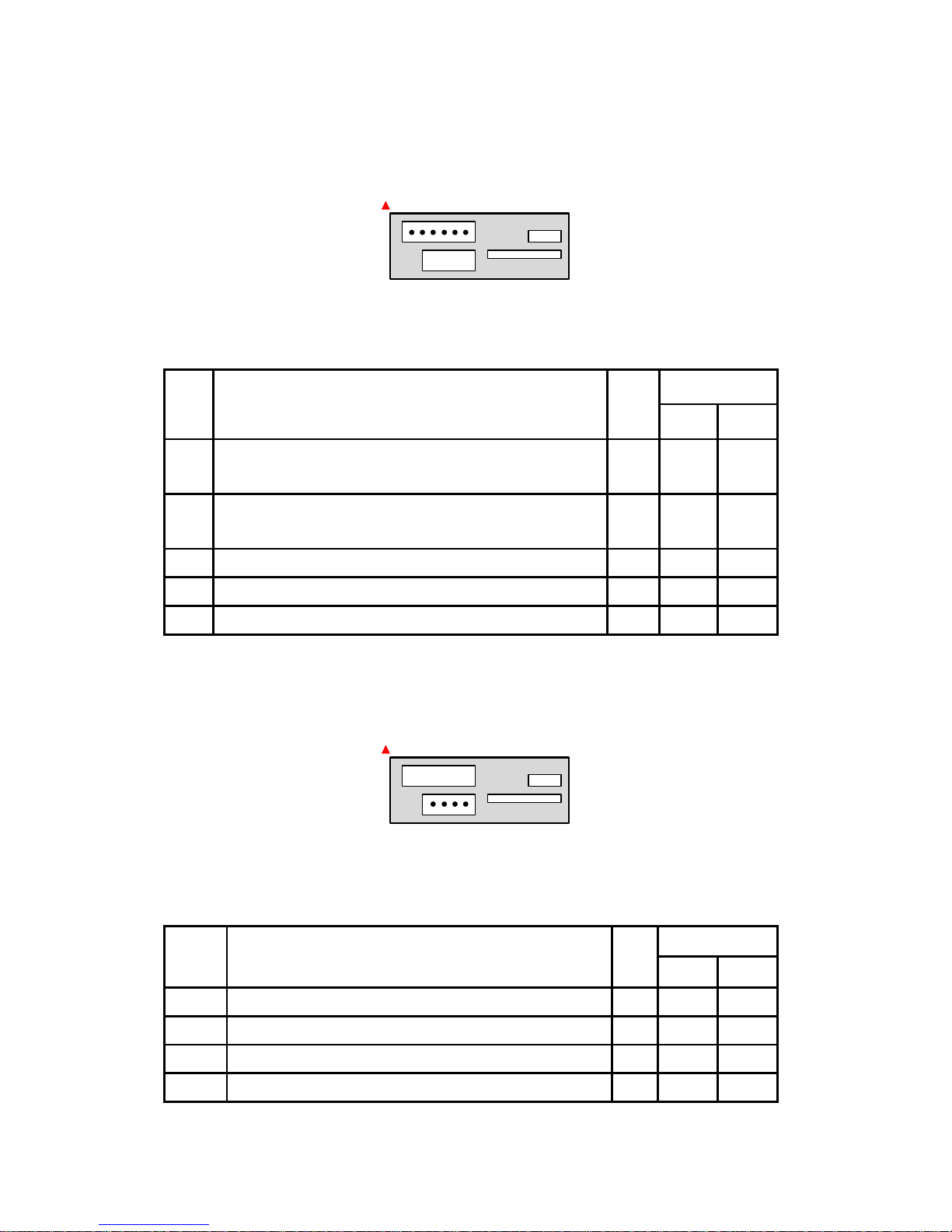
3-2 Pinout of 6-Pin Connector
1 62 3 4 5
Figure 3-2
The red spot indicates the top side.
No.
Description
I/O
Voltage
Min
Max
1
Power input to Alpha when USB connector power unconnected
Power output from Alpha if USB connector power is connected
PWR
3.3V
4.6V
5.5V
5.0V
2
UART input for base data, RTCM3.x or SkyTraq raw
measurement format
IN
3.0V
3.6V
3
UART output for NMEA message
OUT
3.0V
3.3V
4, 5
NC 6
Ground
PWR
Table 3-2
3-3 Pinout of 4-Pin Connector
1 234
Figure 3-3
The red spot indicates the top side
No.
Description
I/O
Voltage
Min
Max
1
DC power output from Alpha to external device
OUT
3.1V
3.3V
2
1PPS (1 pulse per second) output signal
OUT
3.1V
3.3V
3
External camera trigger input signal
IN
1.5V
5.0V
4
Ground
IN
Page 8
8
Table 3-3
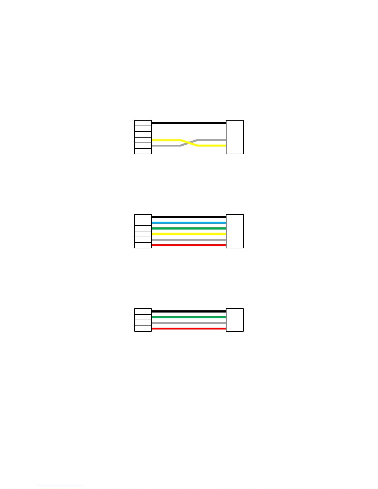
3-4 Connector Cables for Alpha
There are several types of connector cable supplied with the Alpha RTK Kit for different applications.
3-4-1 Wire for connecting Base-to-Rover (for base/rover pair short baseline testing)
Black
Yellow
White
6-pin Connector 6-pin Connector
Figure 3-4
3-4-2 Wire for connecting Rover-to-UAV
Black
Blue
Green
Yellow
White
Red
6-pin Connector 6-pin Connector
Figure 3-5
3-4-3 Wire for connecting Rover-to-Camera
Black
Green
White
Red
4-pin Connector 4-pin Connector
Figure 3-6
Page 9

9
3-4-4 Wire for 6-pin TTL connector with pitch 2.54 Dupont Lines
Black
Blue
Green
Yellow
White
Red
6-pin Connector
Black
Blue
Green
Yellow
White
Red
2.54 Dupont Female
Connector
Figure 3-7
3-4-5 Wire for 4-pin TTL connector with pitch 2.54 Dupont Lines
Black
Green
White
Red
4-pin Connector
Black
Green
White
Red
2.54 Dupont Female
Connector
Figure 3-8
Page 10
10
4. Application Scenarios
4-1 Special Short Baseline Experimental Setup
Base
TTL mode / switch on A
Rover
TTL mode / switch on B
Micro-USB
cable
Micro-USB
cable
6-pin 3 wire for Base-to-Rover (sec. 3-4-1)
Setup for Special Short Baseline Experiment
RTK
antenna
RTK
antenna
. . .
Alpha RTK Alpha RTK
Figure 4-1
For users setting up a local RTK base for use with RTK rover, this experimental setup allows quickly
becoming acquainted with all aspects of Alpha RTK receiver operation. Using our RTK Viewer
Windows-PC software, users can configure Alpha to be base or rover; see section 6 for details.
Page 11
11
Figure 4-2
4-2 RTK Survey and Data Collection
Internet
Bluetooth
Rover
BT mode / switch on B
3rd Party RTK Base
with NTRIP caster
NTRIP
client
3G/4G/LTE
Setup for GIS Data Collection
RTK
antenna
. . .
Alpha RTK
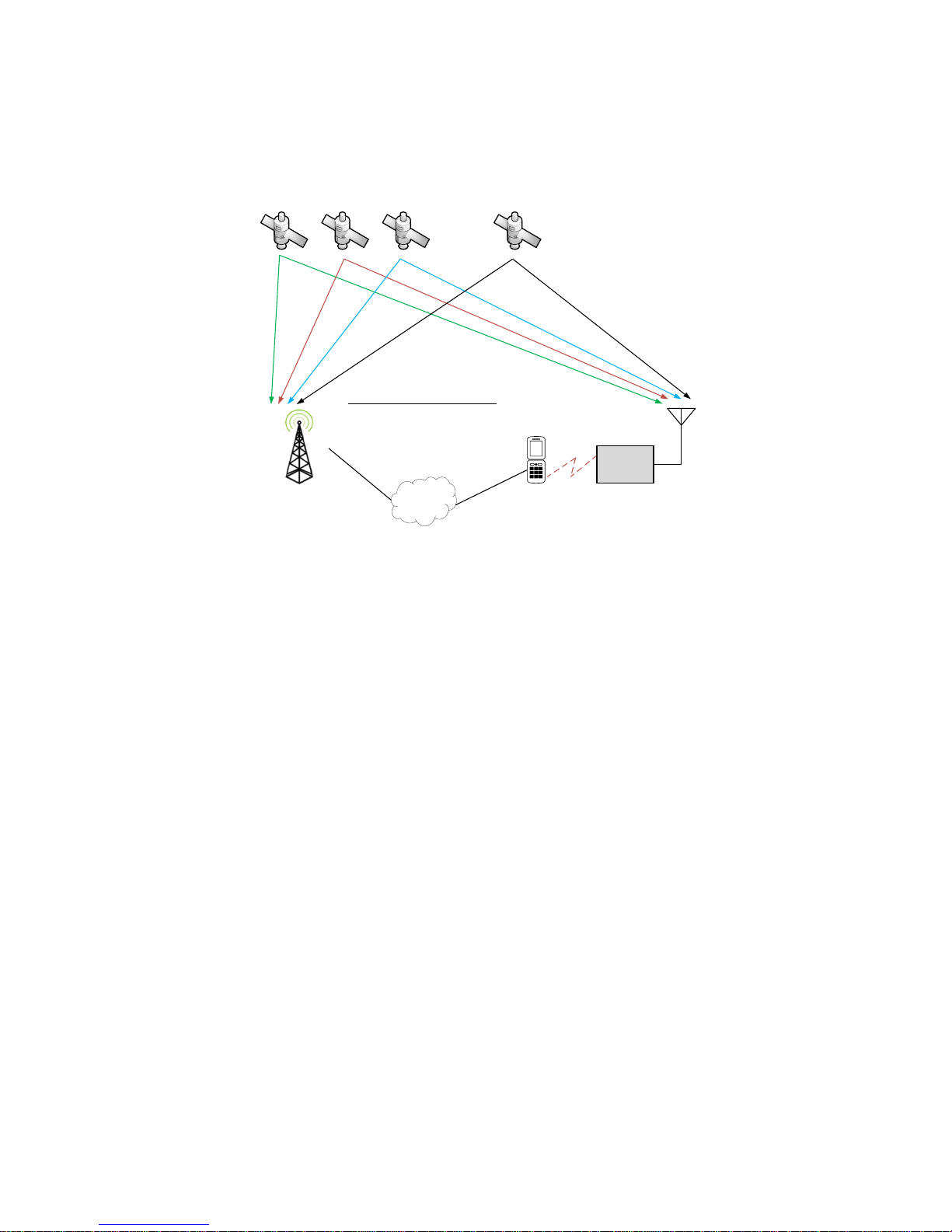
Figure 4-3
When used with Trimble or Leica RTK base station within 10Km distance, or Trimble or Leica RTK base
station with Virtual Reference Station (VRS) service as shown in figure 4-3 for RTK survey and data
collection, then only one Alpha RTK receiver is needed. It’s configured as RTK rover and connects to an
Android smartphone via Bluetooth. User can then run the free Lefebure NTRIP Client App on the
smartphone for retrieving 3rd-party RTK base station data over Internet and sending it to the Alpha
RTK receiver. With “MOCK Location” option enabled on the smartphone, GPS related location Apps on
the smartphone will be able to use the more accurate position from Alpha RTK receiver.
Page 12
12
Base
USB mode / switch on A
Micro-USB
cable
Internet
Bluetooth
Rover
BT mode / switch on B
NTRIP
caster
NTRIP
client
3G/4G/LTE
Setup for GIS Data Collection
RTK
antenna
RTK
antenna
. . .
Alpha RTK Alpha RTK
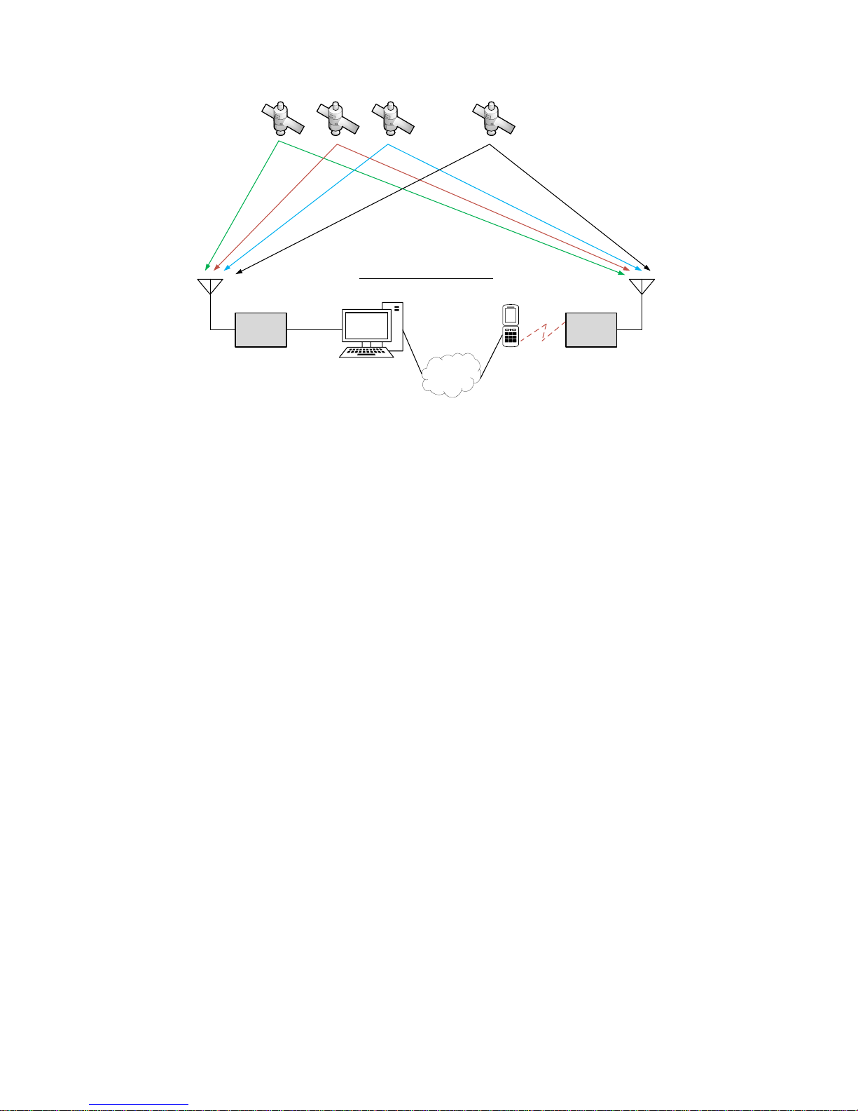
Figure 4-4
In case of setting up a local RTK base with known reference location as shown in figure 4-4 for RTK
survey or data collection, one Alpha RTK receiver is configured as RTK base connecting via micro-USB
port to a computer running NTRIP Server/Caster, and another Alpha RTK receiver is configured as RTK
rover connecting via Bluetooth to an Android smartphone. User can run the free Lefebure NTRIP
Client App on the smartphone to retrieve the Alpha RTK base data over Internet and sending it to the
Alpha RTK rover. With “MOCK Location” option enabled on the smartphone, the GPS related location
Apps on the smartphone will be able to use the more accurate position from Alpha RTK rover.
Page 13
13
4-3 Real-Time Precision Guidance
Base
USB mode / switch on A
Micro-USB
cable
Mission Planner
RTK
antenna
Telemetry
Radio
Telemetry
Radio
Rover
TTL mode / switch on B
RTK
antenna
6-pin wire for
UAV-to-Rover
Setup for UAV
433MHz/915MHz/2.4GHz
Alpha
RTK
Alpha
RTK
. . .
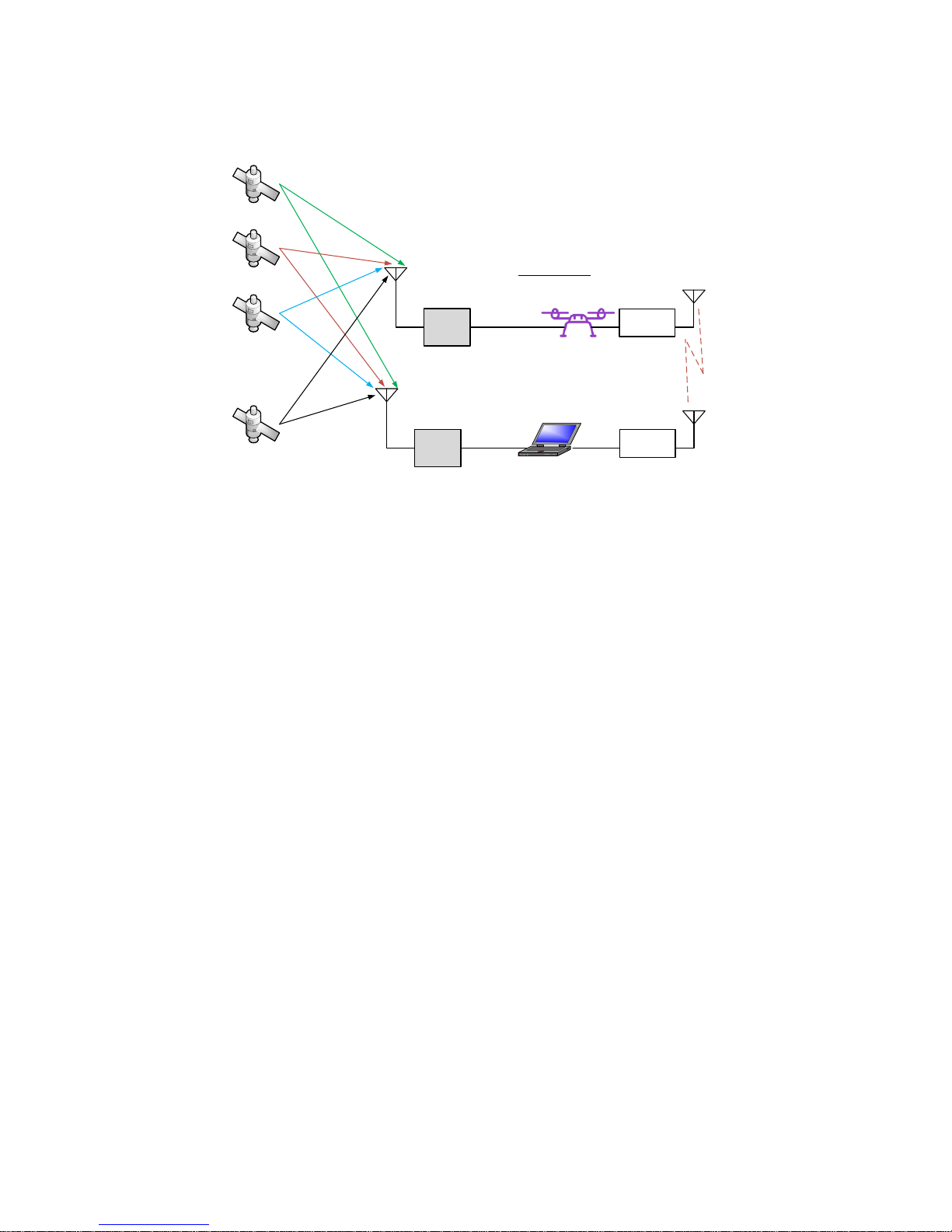
Figure 4-5
When using Alpha RTK receiver in Unmanned Aerial Vehicle (UAV) applications as shown in figure 4-5,
one Alpha is configured as RTK base connecting via micro-USB cable to a computer running Mission
Planner, the computer is also connected with a telemetry radio to communicate with another
telemetry radio installed on the UAV. A second Alpha is configured as RTK rover, connecting to the
autopilot of the UAV via a 6-pin 6 wire cable provided along with the Alpha RTK Kit. In this application
scenario data from RTK base is encapsulated in MAVLink injection protocol sent to autopilot of the
UAV, and autopilot then relays the data to RTK rover, the NMEA message output from RTK rover is sent
to autopilot of the UAV for precision guidance.
Page 14
14
Base
USB/TTL mode / switch on A
TTL or Micro-USB
RTK
antenna
Telemetry
Radio
Telemetry
Radio
Rover
TTL mode / switch on B
RTK
antenna
Pin #2 of 6-pin
TTL connector
Setup for Real-Time Controller over Telemetry Radio
433MHz/915MHz/2.4GHz
Alpha RTK
Alpha
RTK
. . .
Real-Time
Controller
Pin #3 of 6-pin
TTL connector
Figure 4-6
For line-of-sight precision guidance applications that do not use Mission Planner with MAVLink
protocol as in figure 4-6, user can configure one Alpha RTK receiver as RTK base and use 6-pin UART
connector port or micro-USB port to connect to a telemetry radio for sending correction data to the
RTK rover. Another Alpha RTK receiver is configured as RTK rover, using pin-2 of the 6-pin connector to
connect to another telemetry radio for receiving correction data from the RTK base, and using pin-3 of
the 6-pin connector to send RTK NMEA message output to the real-time controller.
Page 15

15
Base
USB mode / switch on A
Micro-USB
cable
Internet
Bluetooth
Rover
BT mode / switch on B
NTRIP
caster
NTRIP
client
3G/4G/LTE
RTK
antenna
RTK
antenna
. . .
Alpha RTK
Alpha RTK
Setup for Real-Time Controller over Internet
Real-Time
Controller
Pin #3 of 6-pin
TTL connector
Figure 4-7
A smartphone can be used to connect RTK rover with RTK base over Internet instead of using a pair of
telemetry radios for non-line-of-sight real-time precision guidance application as shown in figure 4-7.
In this case user can setup an Alpha RTK base as described previously with figure-4-4, and with Alpha
RTK rover also connecting pin-3 of the 6-pin connector to the real-time controller’s UART input for
sending the NMEA output messages to the real-time controller.
Page 16
16
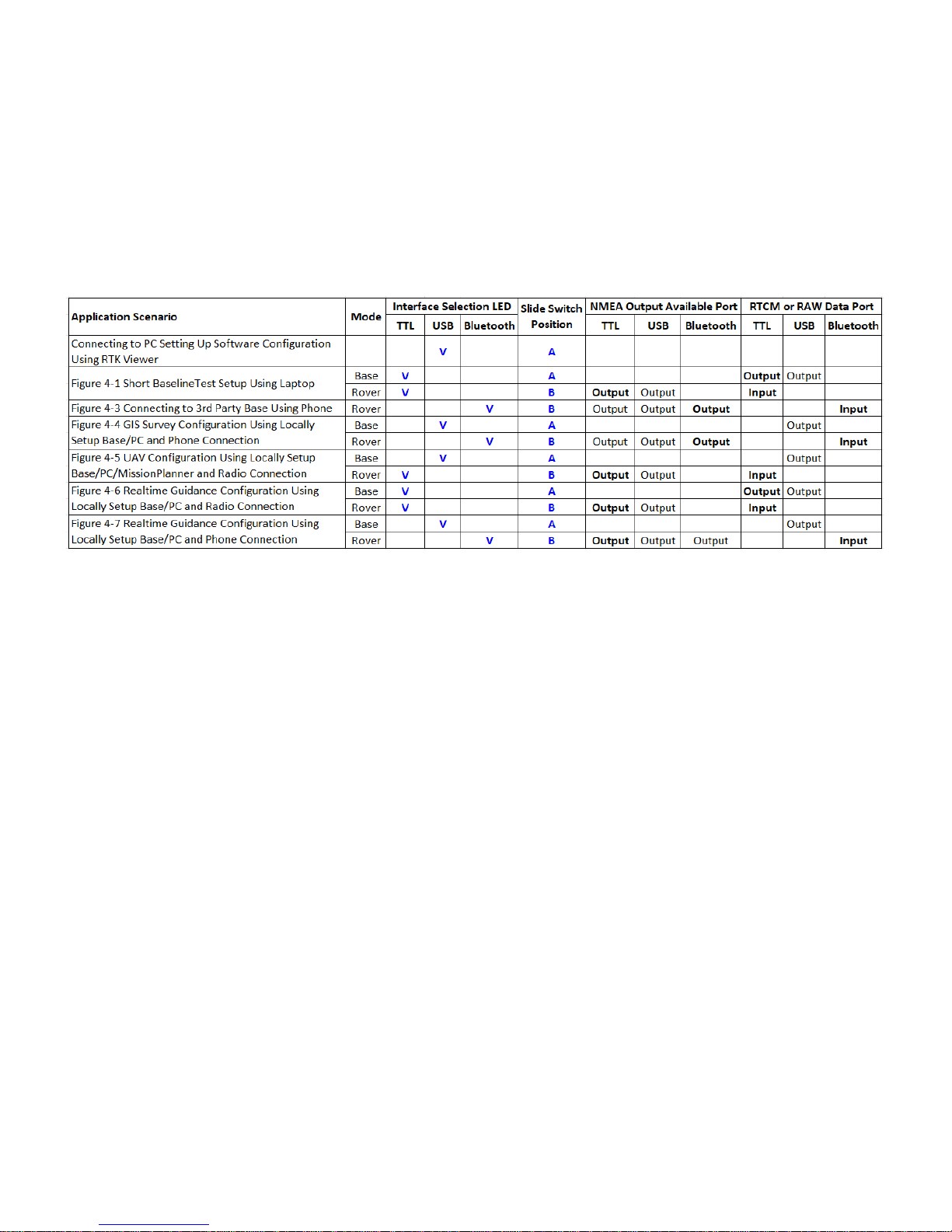
4-4 Hardware Configuration Settings
Table 4-1 shows push button and slide switch configuration settings for Alpha RTK receiver in different
application scenarios. For each usage scenario, V indicates which of the TTL / USB / Bluetooth
interface should be selected to have Alpha’s LED light up, A or B indicates which position to put
Alpha’s slide switch. The boldface Output indicates which NMEA output interface is used for this
usage scenario. The boldface Input indicates which input interface used by rover to receive base data.
Table 4-1
Page 17

17
5. Preparing for First-Time Use
5-1 RTK Viewer
RTK Viewer is a Windows-based software for configuring or monitoring Alpha RTK receiver. User can
download the software from below link:
https://www.polaris-gnss.com/rtk-viewer.zip
5-2 USB Driver
USB driver from Silicon Labs may need to be installed:
https://www.silabs.com/products/development-tools/software/usb-to-uart-bridge-vcp-drivers
5-3 Checking Alpha Receives Satellite Signal
Below steps bring up Alpha as normal GPS receiver to receive satellite signal:
Connect antenna to the Alpha SMA connector and place antenna at a window side having good
sky view. Put Alpha’s slide switch to A position.
Open RTK Viewer. Connect Alpha to PC using micro-USB cable. A dialog box for COM port and
baud rate will appear. Click “Connect”.
Figure 5-1
Click Alpha’s push button to select USB interface. NMEA output should be seen on the Message
screen. If having good sky view with sufficient number of satellites tracked, the signal bar will
turn solid and have position fix.
Page 18

18
Figure 5-2
Tip: if not sure which COM port is used by Alpha, can use Windows “Device Manager” to find out.
Figure 5-3
Page 19

19
6. RTK Setup
6-1 Introduction
Typical uses of Alpha RTK receiver are (1) rover-only: Alpha works with a 3rd party RTK correction data
provider, (2) base/rover pair: two Alphas are configured as a base and a rover, respectively.
For rover-only usage, Alpha RTK receiver can be used with RTK base station service providers having
Virtual Reference Station (VRS) service, or a physical RTK base station within 10Km distance. Typical
setup would be to use an Alpha RTK rover connecting via Bluetooth to Android phone running NTRIP
Client that connects with RTK base station over Internet. Alpha can work with popular Trimble and
Leica base stations.
For base/rover pair usage, the applications could be: (1) an Alpha RTK receiver setup as local RTK base
at some known reference location to serve other Alpha RTK receiver rovers within 10Km distance, (2)
An Alpha RTK receiver first connecting to RTK base station service to determine its position accurately
then later setup as local RTK base to serve other Alpha RTK receiver rovers within 10Km distance.
Page 20

20
6-2 Configuring the Rover
To configure Alpha as RTK rover, put slide switch to position A, connect micro-USB cable to Alpha and
a Windows PC running RTK Viewer. From the “Settings” pull-down menu on RTK Viewer select
“Configure RTK Mode”. On the dialog box select “Configure as Rover” and press “Next” button.
Figure 6-1
On the next dialog box select “NMEA Message” for most applications. “UAV Binary Message” is to be
selected only if using Alpha with ArduPilot/Pixhawk.
Figure 6-2
When done, put slide switch to position B for later use as RTK rover.
Page 21

21
6-3 Configuring the Base
To configure Alpha as RTK base, put slide switch to position A, setup base antenna at location having
unblocked sky view, connect antenna to Alpha using RF cable, connect Alpha to a Windows PC running
RTK Viewer using micro-USB cable. From the “Settings” pull-down menu on RTK Viewer select
“Configure RTK Mode”. On the dialog box select “Configure as Base” and press “Next” button.
Figure 6-3
On the next dialog box, Operating as RTK base, Alpha can output base data in SkyTraq raw
measurement format or RTCM format. For UAV application using Mission Planner, RTCM format is
preferred to reduce the amount of data being sent. For all other applications, SkyTraq raw data format
is preferred.
Figure 6-4
Page 22

22
On the next dialog box, there are 4 ways to configure the base antenna position:
Figure 6-5
6-3-1 Input Fixed Base Antenna Coordinate
When a reference point with known coordinate is available to setup the RTK base antenna, this option
is to be selected. Coordinate of the L1 antenna phase center position, extending from the known
reference point, is to be entered.
Figure 6-6
Page 23

23
There are 3 different formats for entering the longitude and latitude: in degrees, degree/minute, or
degree/minute/second.
Figure 6-7
After pressing “Accept”, the entered coordinate will be set to Alpha permanently. Each time powered
on, Alpha will function as RTK base and use the coordinate for antenna position reporting.
6-3-2 Set Receiver to Self-Survey Approx. Coordinate for 60sec Each Time Powering Up
With this setting, every time Alpha is powered up it’ll use the averaged position of initial 60 position
fix for base antenna position reporting. This may be useful for RTK testing situations where position of
the base will be moved from time to time, and rover’s centimeter-level accuracy relative-positioning
from the base is more important than having accurate position from a global reference.
Figure 6-8
Page 24

24
6-3-3 Set Receiver to Self-Survey Approx. Coordinate for 60sec and Set It As Fixed Base Antenna
Coordinate Permanently
This setting is similar to 6-4-2 except self-survey will be performed immediately and the averaged
position will be used to set permanent base antenna coordinate. Afterwards powering up, Alpha will
use that antenna position coordinate for base antenna position reporting.
Figure 6-9
6-3-4 Using RTK Base Station to Determine Base Antenna Coordinate and Set It As Fixed Base
Antenna Coordinate
This setting uses public or private RTK base station service to determine base antenna position and set
it as fixed base antenna position. Below procedures need to be first performed on the to-be RTK base
Alpha receiver:
Change Alpha’s interface selection to Bluetooth
Put slide switch to position B
Connect Alpha to base station service via Android phone as described in section 6-4-2.
This prepares Alpha RTK receiver as 3rd-party base station connected RTK rover, able to determine its
position to centimeter-level accuracy. Have a USB cable connecting Alpha and RTK Viewer, we can now
select this 4th option to setup the Alpha RTK base antenna position. RTK Viewer will take 60 RTK Fix
position averaged value to set permanent base antenna coordinate. When done, put slide switch back
to position A for Alpha to function as base.
Page 25

25
6-4 RTK Application Scenarios In Detail
This section we go into details on application scenarios.
Table 6-1
6-4-1 Short Baseline Test Setup
Base
TTL mode / switch on A
Rover
TTL mode / switch on B
Micro-USB
cable
Micro-USB
cable
6-pin 3 wire for Base-to-Rover (sec. 3-4-1)
Setup for Special Short Baseline Experiment
RTK
antenna
RTK
antenna
. . .
Alpha RTK Alpha RTK
Figure 6-10
Configure one Alpha as rover (cf. section 6-2). Configure the other Alpha as a base with option "Set
Receiver to Self-Survey Approx. Coordinate for 60sec Each Time Powering Up" (cf. section 6-3-2)
Page 26

26
Figure 6-11
In this base/rover short baseline test setup, the communication link from base to rover is using UART
port on the 6-pin TTL connector port. Use the supplied Base-to-Rover connector cable to connect
Alpha RTK base and Alpha RTK rover. The USB cable connecting to the laptop supplies power and is
also used for monitoring using RTK Viewer.
Testing under open sky environment where the antennas can have clear view of the sky, both base
and rover should be able to pick up 10 or more signals with signal strength in range of 40 ~ 50 dB/Hz.
If using the smaller High Precision Antenna, putting a 10cm x 10cm or larger metallic plate underneath
the antenna will much improve RTK performance.
The rover will first show GPS or DGPS status; a while later it will show Float RTK status, then after
some time it will show Fix RTK denoting it has converged to RTK centimeter-level accuracy solution.
Select “RTK Info” tab to show additional RTK related information. RTK Age shows the time delay rover
receives the base data. Float RTK status turns in to Fix RTK status when RTK Ratio reached 3 or higher
value. When base data is being received, after a while Float RTK status will show if receiving 10 or
more signals under open sky. If the shown status remains to be in GPS or DGPS mode one minute later
after setting up, then rover is not correctly receiving base data.
Page 27

27
Figure 6-12
With the right side Scatter View on RTK Viewer, “Set Origin” button can be clicked to re-center, the
“Scale” pull down menu allows adjusting scatter plot viewing range.
On left hand side bottom, clicking “Cold Start” button restarts the receiver from scratch; clicking “Hot
Start” button restarts the receiver without clearing internal data.
6-4-2 Connecting to 3rd Party Base Using Phone
Internet
Bluetooth
Rover
BT mode / switch on B
3rd Party RTK Base
with NTRIP caster
NTRIP
client
3G/4G/LTE
Setup for GIS Data Collection
RTK
antenna
. . .
Alpha RTK
Figure 6-13
Page 28
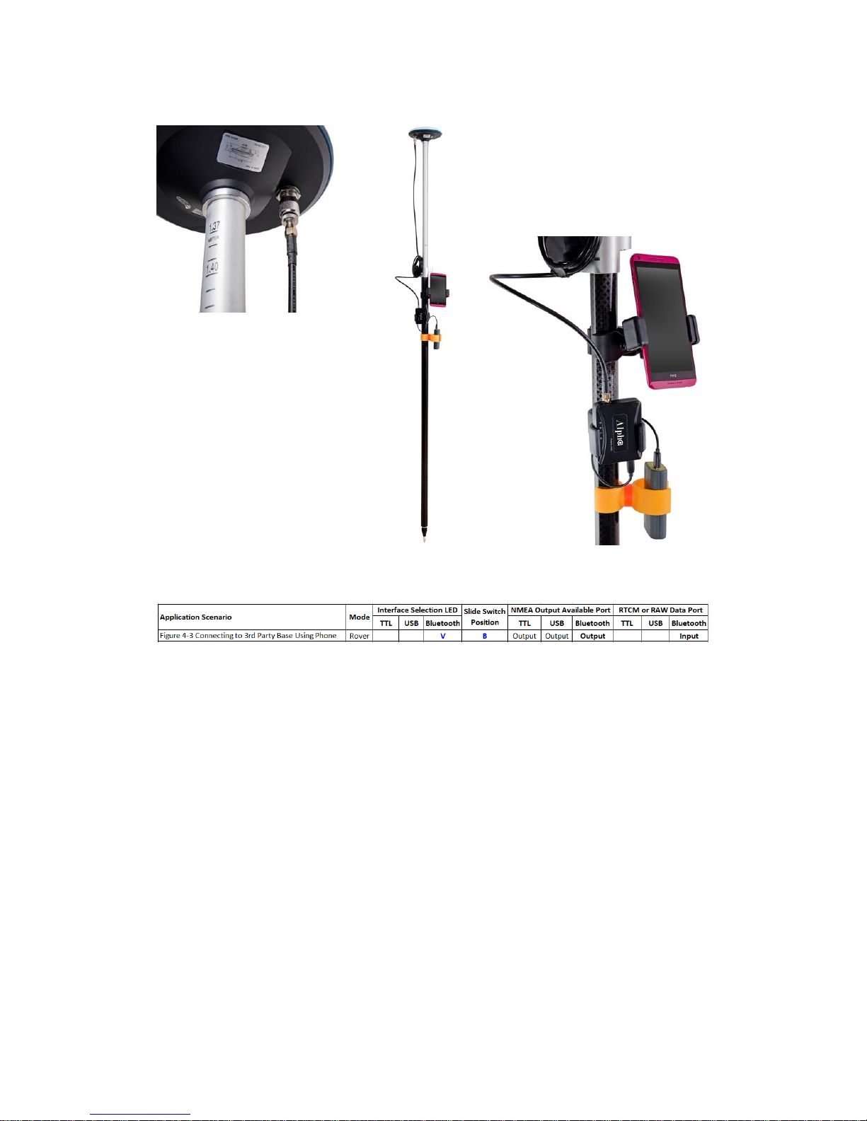
28
Use section 6-2 method to configure Alpha into RTK rover.
Figure 6-14
Once Alpha RTK rover setting is configured, use below steps to prepare for connecting to 3rd party RTK
base station:
1. Mount the rover antenna on a range pole or tripod.
2. Mount Alpha RTK receiver, power bank, and smartphone to range pole or tripod using
holders.
3. Use antenna cable to connect antenna and Alpha.
4. Use USB cable to connect power bank and Alpha.
5. Turn on power bank to supply 5V to power Alpha
6. Turn on Bluetooth of Android phone, scan for “BT SPP xxxxxx” device, select to pair.
Page 29

29
7. Install Lefebure NTRIP Client from Google Play Store, open it.
8. Select the gear setup icon on the upper right corner. Select “Receiver Settings”.
Page 30

30
9. For “Receiver Connection” select “External via Bluetooth”. For “Bluetooth Device” select the
“BT SPP xxxxxx” device. Check “GPS Mock Locations”.
10. Select “NTRIP Settings”. Network Protocol select “NTRIP v1.0”. Enter base station and
account information for Caster IP / Caster Port / Username / Password / Data Stream.
Report Location select “Get From External Receiver”.
Page 31

31
11. Enable phone’s Mobile Data connection. Select the gear icon on upper right to enter phone
Settings configuration page.
12. Select “Developer Options” near the bottom of Settings page. Sliding down Developer
Options page, select “Mock Location App”.
Page 32

32
13. Select “Lefebure NTRIP Client”.
14. Return to Lefebure NTRIP Client App, click “Connect” to connect with Alpha RTK receiver via
Bluetooth and RTK base station via Internet.
Page 33

33
15. After connection is made, upper left screen will first show Invalid, denoting receiver does
not have position fix yet. Next it’ll show GPS or DGPS and number of satellites used,
denoting receiver has meter-level accuracy position fix. Then it’ll show FloatRTK for some
time, denoting the receiver is trying to converge to centimeter-level accuracy position.
When the receiver has centimeter-level accuracy position it’ll show steady RTK status.
Afterwards third party Data Collector Apps can next be used to record the position.
Page 34

34
16. When surveying a group of locations within walking distance, can leave Alpha powered up,
taking the range pole or tripod to next location to survey. Switch to the Lefebure NTRIP
Client App to check if Alpha is in RTK Fix state before recording the next location position
with Data Collector App. The setup procedure only needs to be performed once. Later use
only need to run Lefebure NTRIP Client and connect.
6-4-3 GIS Survey Configuration Using Locally Setup Base/PC and Phone Connection
Base
USB mode / switch on A
Micro-USB
cable
Internet
Bluetooth
Rover
BT mode / switch on B
NTRIP
caster
NTRIP
client
3G/4G/LTE
Setup for GIS Data Collection
RTK
antenna
RTK
antenna
. . .
Alpha RTK Alpha RTK
Figure 6-15
Use section 6-2 method to configure one Alpha receiver into RTK rover. Depending on what’s available
to determine base antenna position, select one of the options to configure the second Alpha RTK
receiver into RTK base as described in section 6-3.
Once Alpha RTK base and rover settings are properly configured and able to get rover RTK Fix with
short baseline experiment as described in section 6-4-1, one can proceed to setup base to send data
over Internet.
If having fixed IP to setup a local base, one can use RTKLIB’s STRSVR to setup NTRIP Server/Caster RTK
base station to work with remote NTRIP Client. Please refer to Appendix A-3 for setup procedures.
Page 35

35
Polaris offers a very low-cost subscription service that allows customers, who do not have fixed IP
Internet connection, to setup RTK base station using open-source RTKLIB’s STRSVR to stream the base
data to our re-directing server. The Lefebure NTRIP Client running on customer’s Android phone can
then connect to our re-directing server to fetch the streamed base data. This way no fixed IP is
required to setup RTK base station. Refer to Appendix A-2 for setup procedures.
After local RTK base for Internet NTRIP connection is prepared, setup procedure as described in
section 6-4-2 is to be applied to use the RTK rover.
6-4-4 UAV Configuration Using Locally Setup Base / PC / Mission Planner and Radio Connection
Base
USB mode / switch on A
Micro-USB
cable
Mission Planner
RTK
antenna
Telemetry
Radio
Telemetry
Radio
Rover
TTL mode / switch on B
RTK
antenna
6-pin wire for
UAV-to-Rover
Setup for UAV
433MHz/915MHz/2.4GHz
Alpha
RTK
Alpha
RTK
. . .
Figure 6-16
Use section 6-2 method to configure one Alpha receiver into RTK rover. Depending on what’s available
to determine base antenna position, select one of the options to configure the second Alpha RTK
receiver into RTK base as described in section 6-3.
Once Alpha RTK base and rover settings are properly configured and able to get rover RTK Fix with
short baseline experiment as described in section 6-4-1, one can proceed to setup base/rover for UAV
application.
Page 36

36
ArduPilot is the most popular, full-featured and reliable open source autopilot software. It provides a
"RTK/GPS injection" method of using only one pair of radio for sending RTK base correction data and
Mission Planner data. Items needed for building a complete RTK system are shown below.
Figure 6-17
Since Mission Planner expects RTCM format base data, user must configure the Alpha RTK base to
output in RTCM as described in section 6-3-5.
Page 37

37
Open Mission Planner and follow below steps:
Select the 【INITIAL SETUP】 tab on top of GUI.
Select the 【RTK/GPS Inject】 icon on left panel of GUI.
Select the COM port on which Alpha RTK base is assigned for the USB connection.
Select 115200 baud rate that Alpha RTK base output RTCM data to Mission Planner.
Check the 【Inject MSG Type】 feature.
Press the 【Connect】 icon and you should see it becomes 【Stop】.
Once having done above configurations, one should see below screen.
Figure 6-18
Page 38
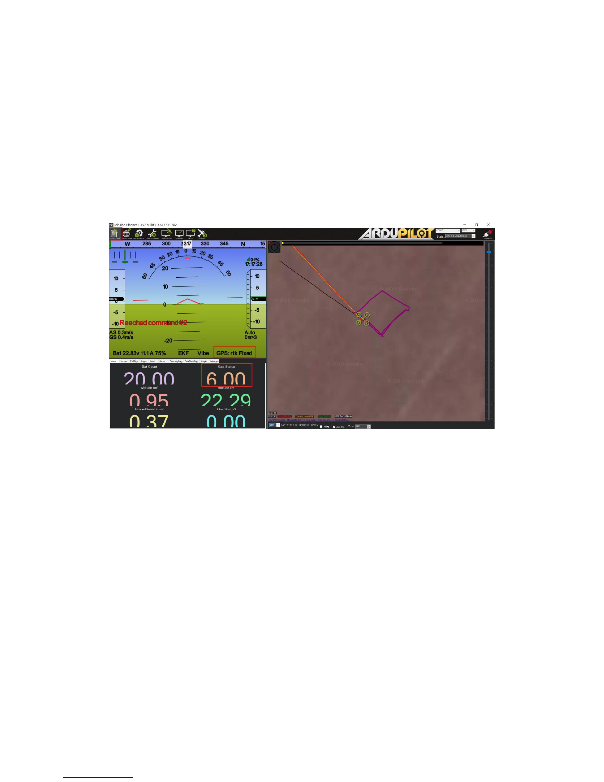
38
Select 【Flight Data】 icon on the top menu bar to return to main page, Mission Planner will show
current GPS status in below red rectangle enclosed area, and user could check and see if it’s working
correctly.
GPS: RTK Fixed GPS Status = 6.00
GPS: RTK Float GPS Status = 5.00
GPS: 3D DGPS GPS Status = 4.00
GPS: 3D Fix GPS Status = 3.00
Figure 6-19
Page 39

39
6-4-5 Real-Time Guidance Configuration Using Locally Setup Base/PC and Radio Connection
For line-of-sight real-time control application, telemetry radio can be used to send RTK base
data.
Base
USB/TTL mode / switch on A
TTL or Micro-USB
RTK
antenna
Telemetry
Radio
Telemetry
Radio
Rover
TTL mode / switch on B
RTK
antenna
Pin #2 of 6-pin
TTL connector
Setup for Real-Time Controller over Telemetry Radio
433MHz/915MHz/2.4GHz
Alpha RTK
Alpha
RTK
. . .
Real-Time
Controller
Pin #3 of 6-pin
TTL connector
Figure 6-20
Use section 6-2 method to configure one Alpha receiver into RTK rover. Depending on what’s available
to determine base antenna position, select one of the options to configure the second Alpha RTK
receiver into RTK base as described in section 6-3.
Assume the radio is properly setup for sending and receiving RTK base data at 115200 baud rate, (1)
connect RTK base UART output on pin-3 and GND on pin-6 of the 6-pin connector to radio transmitter,
(2) connect RTK rover UART input on pin-2 and GND on pin-6 of the 6-pin connector to radio receiver,
(3) connect RTK rover UART output on pin-3 of the 6-pin connector and GND on pin-4 of the 4-pin
connector to the real-time controller, apply power to both radios then RTK rover will be able to
receive RTK base data and function.
Page 40

40
6-4-6 Real-Time Guidance Configuration Using Locally Setup Base/PC and Phone Connection
For longer range non-line-of-sight real-time control application, NTRIP Internet connection
can be used to send RTK base data.
Base
USB mode / switch on A
Micro-USB
cable
Internet
Bluetooth
Rover
BT mode / switch on B
NTRIP
caster
NTRIP
client
3G/4G/LTE
RTK
antenna
RTK
antenna
. . .
Alpha RTK
Alpha RTK
Setup for Real-Time Controller over Internet
Real-Time
Controller
Pin #3 of 6-pin
TTL connector
Figure 6-21
Use section 6-2 method to configure one Alpha receiver into RTK rover. Depending on what’s available
to determine base antenna position, select one of the options to configure the second Alpha RTK
receiver into RTK base as described in section 6-3.
Use the same method as described in section 6-4-3 to setup base/rover Internet NTRIP connection
capability. Connect RTK rover UART output on pin-3 and GND on pin-6 of the 6-pin connector to the
real-time controller, then it’s ready to use!
Page 41

41
7. Configure RTK License
The shipped Alpha RTK receiver in UPM-Lite or UPM-Std Kit functions like a normal meter-level
accuracy GNSS receiver prior to Usage Plan purchase and RTK activation license is applied.
When Usage Plan is purchased, an email will be received by the customer requesting information on
(1) Alpha Serial Number (2) Activation Start Date if One Year Usage Plan is purchased. To check the
Alpha Serial Number, from RTK Viewer’s Viewer pull-down menu select “Configure RTK License”, click
“Copy Serial Number” button, then paste it to the reply email. Later when receiving License key,
simply copy and paste it to the License Key entry and click “Activate”.
Figure 7-1
Page 42

42
8. Raw Measurement Recording and Post Processing
For post-processing, both base data and rover data need to be available. The base data can be (1)
stored RTCM data received from RTK base station service or (2) stored SkyTraq raw measurement data
from Alpha RTK base. The RTK rover data is stored SkyTraq raw measurement data from Alpha RTK
rover.
To store raw measurement data, the supplied 16GByte SD Card needs to be inserted into Alpha’s SD
Card holder. To enable raw measurement recording, pressing the push button for 3 seconds until SD
Card LED turns ON. When SD Card is recording the LED will flash. Pressing the push button for another
3 seconds until SD Card LED ceases flashing will stop raw measurement recording. To avoid recording
file corruption, always stop raw measurement recording before powering off Alpha.
The logged raw measurement data or RTCM data can be converted to RINEX format using v.2.4.3
RTKLIB’s RTKCONV program. After converting base and rover logged data into standard RINEX format,
they can be post-processed using RTKLIB’s RTKPOST or other post-processing software.
Page 43

43
9. Software Update
Occasionally there will be new update software for RTK Viewer and Alpha RTK receiver. User can
manually check and update using RTK Viewer on computer with Internet connection.
9-1 RTK Viewer Software Update
To check if update for RTK Viewer is available, select “Check RTK Viewer Update” from the Viewer
pull-down menu.
Figure 9-1
9-2 Alpha RTK Receiver Software Update
Before checking if new update software for Alpha is available, make sure Alpha is connected to RTK
Viewer. From RTK Viewer “Updates” pull-down menu, select “Check Firmware Update”, then a
message box showing “checking for updates” will pop up.
Page 44

44
Figure 9-2
If no new update is available, RTK Viewer will notify already running latest software.
Figure 9-3
In case new update software is found, a dialog box will appear. Press “Yes” to update, or “No” to
cancel update.
Figure 9-4
Page 45
45
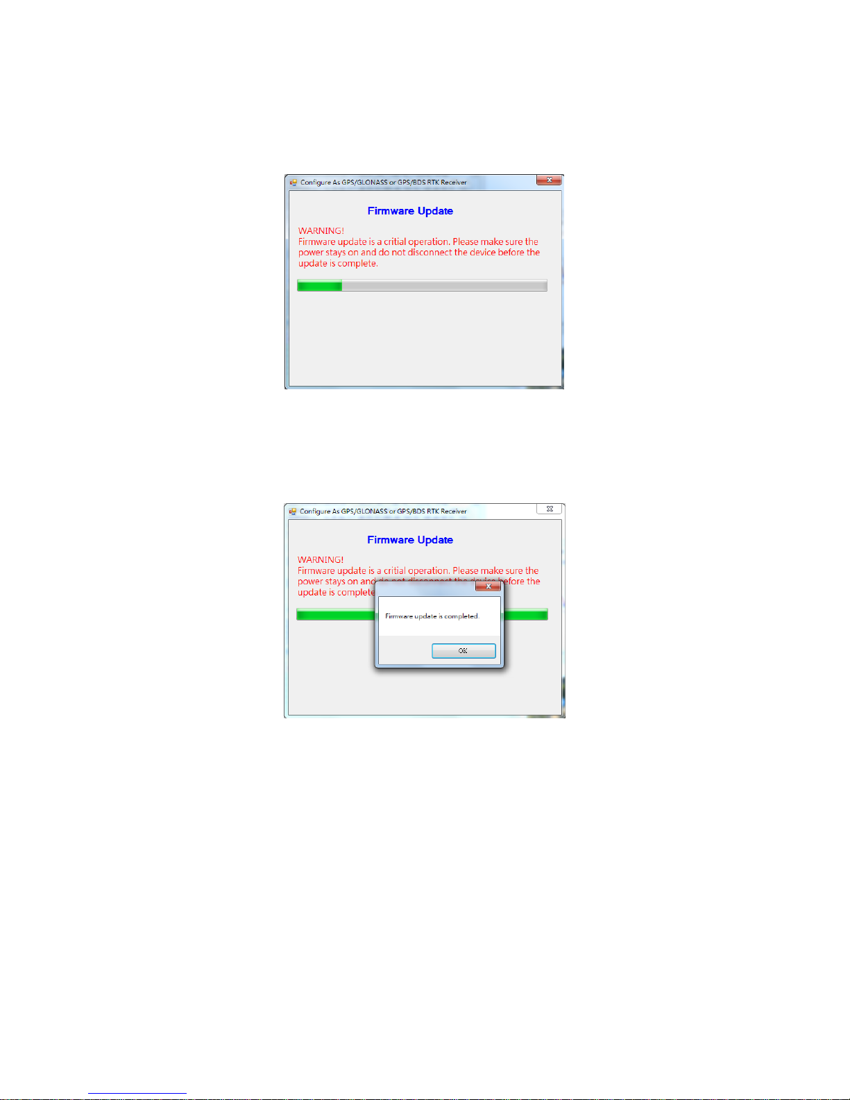
After pressing “Yes” RTK Viewer will download the new software from Polaris’ website and load it to
Alpha, RTK Viewer will show below message box indicating software update status.
Figure 9-5
When software update is in progress, DO NOT remove the USB cable, or press Alpha’s push button, or
change position of the slide switch until seeing software update is completed.
Figure 9-6
Page 46
46
APPENDIX
A-1. Additional Software Configurations
A-1-1. Configure Baud Rate
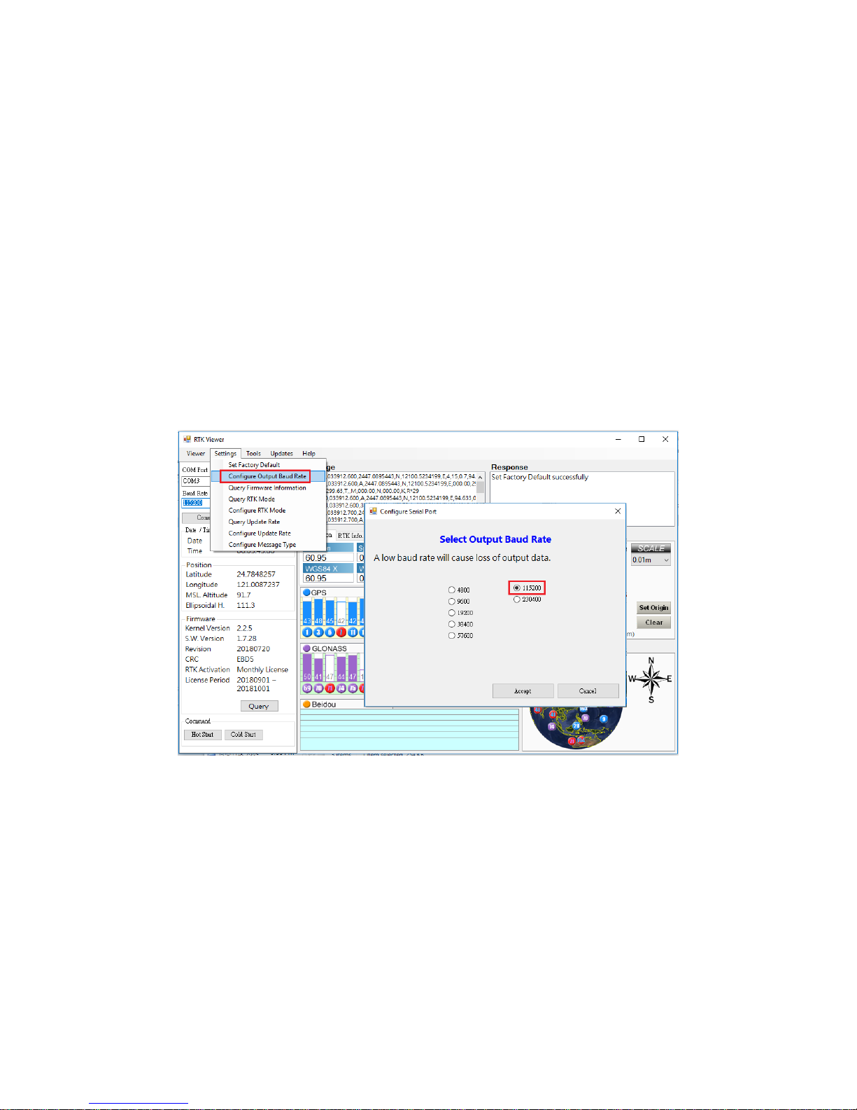
Alpha supports multiple NMEA output baud rates on UART and USB interface while the baud rate of
Bluetooth is fixed at 115200. User should NOT use any baud rate other than 115200 when Bluetooth
interface is selected, or it’ll not be possible to get RTK Fix.
User can change the NMEA output baud rate of UART and USB interface from the Setting pull-down
menu on RTK Viewer, select “Configure Output Baud Rate” and choose the desired baud rate in dialog
box.
Figure A-1-1
Base data input baud rate of Alpha RTK rover is fixed at 115200. Sending base data to rover at
incorrect baud rate will cause the rover unable to receive base data and never enter Float RTK state.
Page 47
47
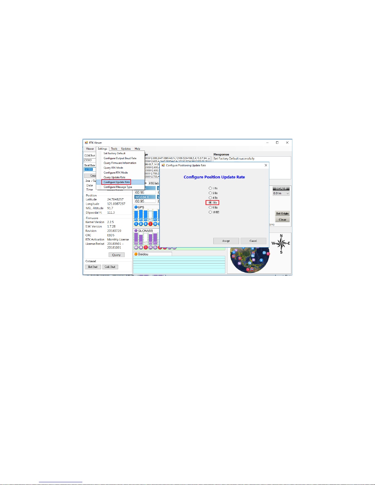
A-1-2. Configure Update Rate
Alpha supports 1 / 2 / 4 / 5 / 8 / 10 Hz RTK update rate; default is 1Hz. Higher update rate can be
useful for precision guidance applications. Update rate command affects $GGA / $RMC / $VTG / $PSTI
030 messages; the other NMEA sentence is slow changing and remains at 1Hz unaffected by update
rate command.
User can change the update rate from Settings pull-down menu of RTK Viewer, select “Configure
Update Rate” and choose the desired update rate.
Figure A-1-2
Page 48

48
A-2. NTRIP Server/Caster Setup for Users Without Fixed IP
Polaris offers a very low-cost subscription service that allows customers without fixed IP to setup RTK
base station using open-source RTKLIB’s STRSVR to stream the base data to a re-directing server. The
Lefebure NTRIP Client running on customer’s Android phone can then connect to the re-directing
server to fetch the streamed base data. This way no fixed IP is required to setup RTK base station.
Since the newest version RTKLIB v.2.4.3 provided on official website is in source code format and
compilation required Borland™ C++ builder, a pre-compiled binary executable is made available at:
https://www.polaris-gnss.com/strsvr.zip. After downloading, unzip it, “strsvr 2.4.3.exe” can be
executed directly.
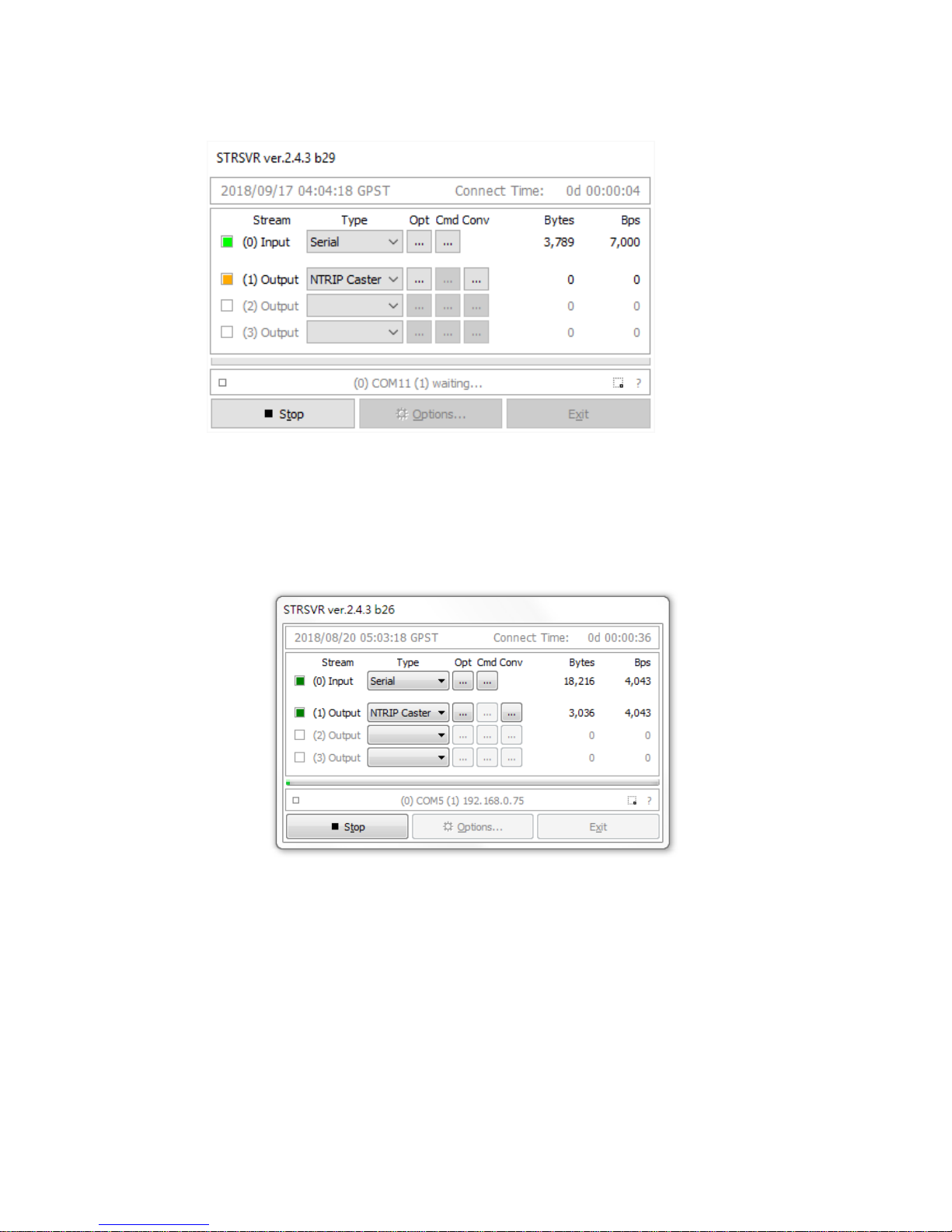
After executing the binary, the main STRSVR dialog screen will appear. Below shows an input data
stream from a serial device and one output data stream to NTRIP Caster.
Figure A-2-1
Follow steps below to set up STRSVR.
1. Set up an input stream of type "Serial" and press the "Opt" button to set the input stream
options.
Figure A-2-2
Page 49

49
2. Configure the input stream options as follows. Press the OK button to return to the STRSVR
dialog when finished.
Field
Description
Example
Port
Select the COM port for base data input
COM7
Bitrate (bps)
Serial port data input bit rate.
115200
Byte Size
Byte Size depends on serial settings.
8 bits
Parity
Parity depends on serial settings.
None
Stop Bits
Stop Bits depends on serial settings.
1 bit
Flow Control
Flow control depends on serial settings.
None
Table A-2-1
Figure A-2-3
3. Setup an output stream of type "NTRIP Server" and press the "Opt" button to set the output
stream options.
Figure A-2-4
Page 50
50
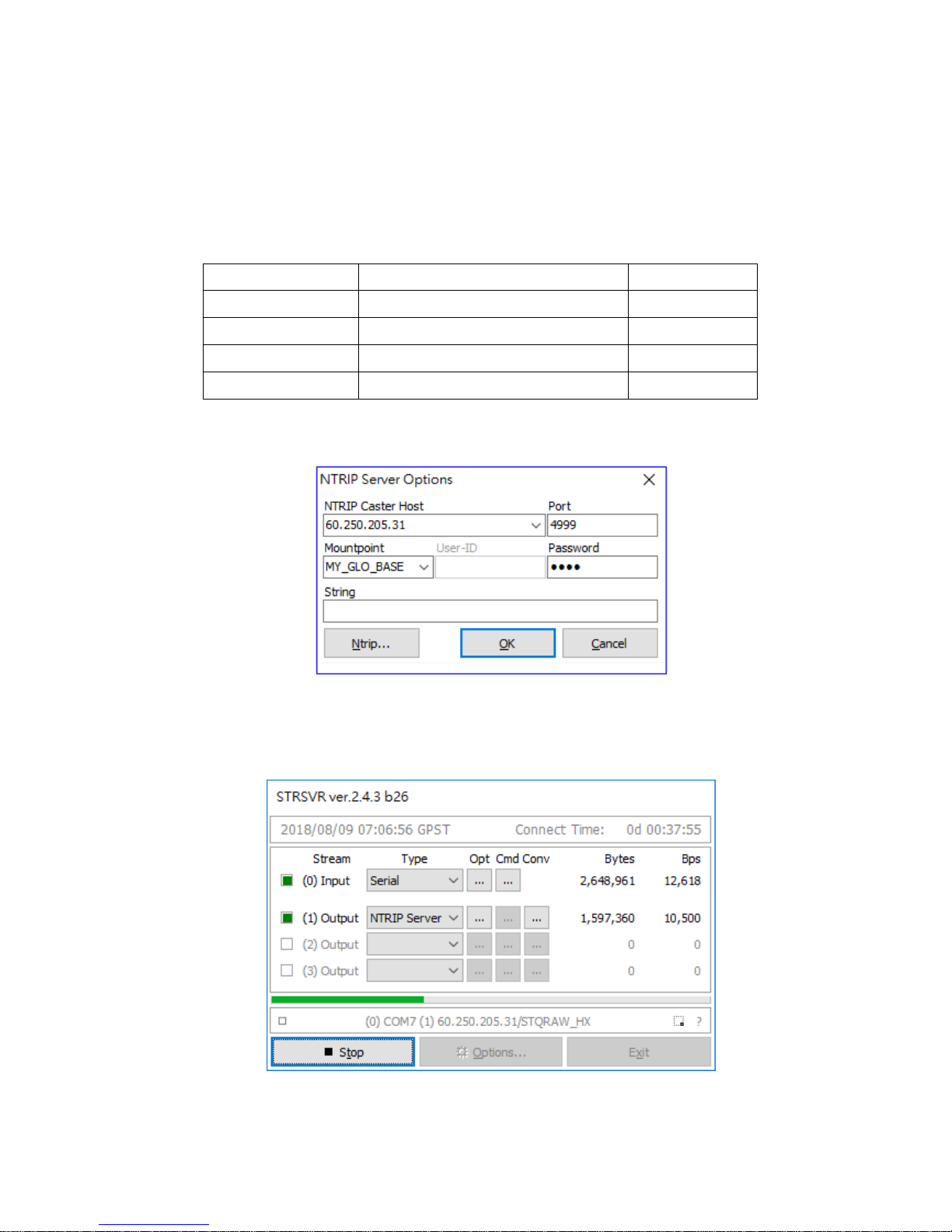
4. Set the output stream options as follows. Press the OK button to return to the STRSVR dialog
when finished. The red color NTRIP Caster Host IP and Port Number are provided by Polaris to
Base Data Redirecting Service subscription customers. The blue color Mountpoint and password
are specified by customer at time of subscription application.
Field
Description
Example
NTRIP Caster Host
Enter the Caster URL, or the machine’s IP.
60.250.205.31
Port
Enter the port used by Caster.
4999
Mountpoint
Enter Caster mount point name
MY_GLO_BASE
password
Enter password to access the base data
1234
Table A-2-2
Figure A-2-5
Press Start button on the STRSVR panel to start sending local RTK base data to the redirecting server.
Figure A-2-6
Page 51

51
A-3 NTRIP Server/Caster Setup for Users With Fixed IP
Since the newest version RTKLIB v.2.4.3 provided on official website is in source code format and
compilation required Borland™ C++ builder, a pre-compiled binary executable is made available at:
https://www.polaris-gnss.com/strsvr.zip. After downloading, unzip it, “strsvr 2.4.3.exe” can be
executed directly.
After executing binary, the main STRSVR dialog screen should appear as shown in below
Figure A-3-1
1. Set up an input stream of type "Serial" and press the "Opt" button to set the input stream
options.
Figure A-3-2
2. Configure the input stream options as follows. Press the OK button to return to the STRSVR dialog
when finished.
Page 52

52
Field
Description
Example
Port
Select the COM port for base data input
COM5
Bitrate (bps)
Serial port data input bit rate.
115200
Byte Size
Byte Size depends on serial settings.
8 bits
Parity
Parity depends on serial settings.
None
Stop Bits
Stop Bits depends on serial settings.
1 bit
Flow Control
Flow control depends on serial settings.
None
Table A-3-1
3. Setup an output stream of type "NTRIP Caster" and press the "Opt" button to set the output
stream options.
Figure A-3-3
4. Set the output stream options as follows. Press the OK button to return to the STRSVR dialog
when finished. The blue color Mountpoint, User-ID and password are specified by user, and rover
can access the base data with this authentication info later on.
Field
Description
Example
NTRIP Caster Host
Grey-out for STRSVR will use local WAN IP
as host IP
None
Port
Enter the port used by Caster.
5000
Mountpoint
Enter Caster mount point name
my_RTK_base
User-ID
Enter user ID to access the base data
test
password
Enter password to access the base data
1234
Table A-3-2
Page 53
53
5. Press the Start button on the STRSVR panel to start the service and wait for the connection.
.
Figure A-3-4
6. After remote NTRIP Client making connection, user should see the screen like following image.
The green square flashes when there is ongoing data transmission and how many bytes have
been transmitted is also shown on screen.
Figure A-3-5
Page 54

54
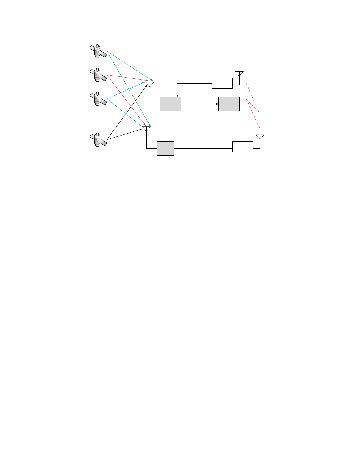
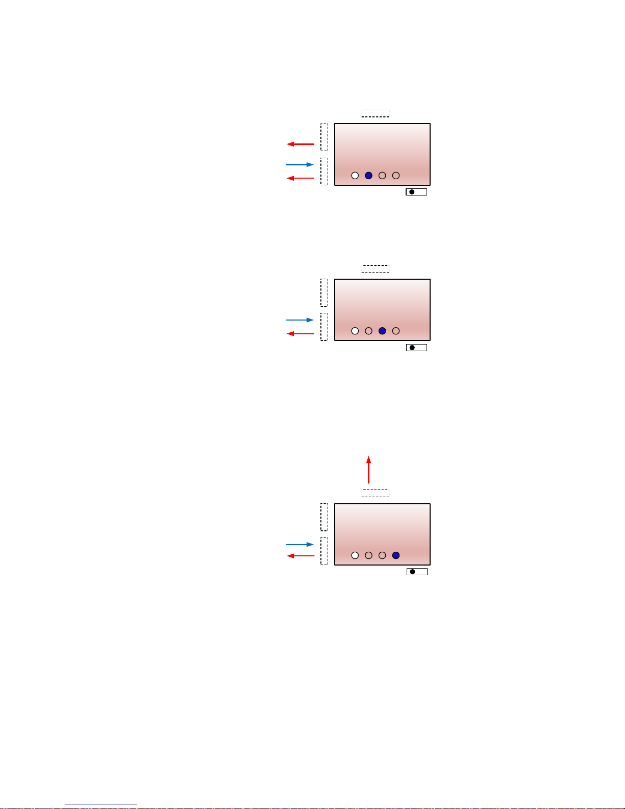
A-4 Data Flow of the I/O Interface
There are 3 types of I/O interface, Bluetooth / USB / LV-TTL UART, on the Alpha RTK receiver for
output of NMEA or base data, receiving base data, and receiving configuration command. The
following figures provide a clear view for all 6 operation modes specified by the three interface
selection LEDs and the two slide switch positions.
Alpha
Polaris RTK
T
U
B
USB TTL
BT
Command from RTK Viewer
NMEA Messages
NMEA Messages
Base Data
B
switch
Figure A-4-1
Alpha
Polaris RTK
T
U
B
USB TTL
BT
NMEA Messages
NMEA Messages
Base Data
B
switch
Figure A-4-2
Alpha
Polaris RTK
T
U
B
USB TTL
BT
NMEA Messages
NMEA Messages
Base Data
NMEA Messages
Command from RTK Viewer
B
switch
Figure A-4-3
Page 55
55
Alpha
Polaris RTK
T
U
B
USB TTL
BT
Base Data
Command from RTK Viewer
Base Data
A
switch
Figure A-4-4
Alpha
Polaris RTK
T
U
B
USB TTL
BT
Command from RTK Viewer
Base Data
A
switch
Figure A-4-5
Alpha
Polaris RTK
T
U
B
USB TTL
BT
Command from RTK Viewer
Base Data
Base Data
A
switch
Figure A-4-6
Page 56

56
The information provided is believed to be accurate and reliable. These materials are provided to customers and may be used for
informational purposes only. No responsibility is assumed for errors or omissions in these materials, or for its use. Changes to
specification can occur at any time without notice.
These materials are provides “as is” without warranty of any kind, either expressed or implied, relating to sale and/or use including
liability or warranties relating to fitness for a particular purpose, consequential or incidental damages, merchantability, or infringement of
any patent, copyright or other intellectual property right. No warrant on the accuracy or completeness of the information, text, graphics
or other items contained within these materials. No liability assumed for any special, indirect, incidental, or consequential damages,
including without limitation, lost revenues or lost profits, which may result from the use of these materials.
The product is not intended for use in medical, life-support devices, or applications involving potential risk of death, personal injury, or
severe property damage in case of failure of the product.
 Loading...