

Page 1
IMPORTANT INFORMATION
OWNER’S MANUAL
POWER
ON
OFF
COLOR
FAST
STOP
SLOW
AfterDark
Page 2

www.polarispool.com
Important Information
Follow these simple guidelines, to protect against injury and prolong the life of your Polaris AfterDark®
light driver.
• The light driver operates on 120VAC, 60Hz. Do not attempt to alter the unit to operate on any other
voltage.
• Always turn off the power supply to the light driver before removing the cover.
• Keep the ventilation slots at the bottom of the unit clear of leaves and debris.
• Do not sit or stand on the light driver, or place anything on top of it.
• Do not submerge the light driver in water or operate it while it is buried in snow. The unit must be
ventilated at all times to avoid damage and voiding of the warranty.
• Do not allow children to play with the light driver.
• The light driver is equipped with a metal-halide lamp which builds brightness gradually. It may take
as long as 2 minutes for the light intensity to peak. If the light driver is shut off after warming up, it
may take up to two minutes to regain full intensity.
• Use only Polaris lamp #AD300 to replace the bulb in this light driver. Failure to do so could result in
bodily injury or damage to the light driver.
• Install the light driver at least five feet (1.5 meters) from the pool, spa or hot tub.
• The Polaris After Dark light driver is designed to work with genuine Polaris fiber optic cable only.
Polaris is not responsible for damage to non-Polaris fiber optic cable.
For customer service or support:
• Please mail Warranty Card immediately.
• For on-line support: www.polarispool.com
• To contact Polaris:
US and Canada Australia Europe
Customer Service Unit 4, 19-21 Gibbes Street, C/Osana s/n.
2620 Commerce Way Chatswood, NSW 2067 (Pol.End.El Ramassar),
Vista, CA 92081-8438 1-300-POLARIS 98520 Les Franqueses del Vallés
1-800-822-7933 ACN 080 168 092 Barcelona, Spain
+34 93 840 25 85
Page 3
www.polarispool.com
Congratulations on the purchase of your new fiber optic lighting system and thank you
for choosing Polaris. The Polaris AfterDark®light driver is designed to provide safe,
beautifully colored lighting and years of trouble-free service.
The brightness of a fiber optic lighting system is determined by many factors including
the cable length, the size of the pool, the color of the pool’s interior, and the amount of
ambient light in the pool area. If you have purchased the AD150 equipped with a Color
Wheel, you will notice variations in color intensity in different colors. Each color emits a
different level of brightness, white is the brightest and magenta is the least bright.
Always insist on genuine Polaris replacement parts. Non-Polaris parts are not made to
our specifications and can adversely affect the operation of your light driver.
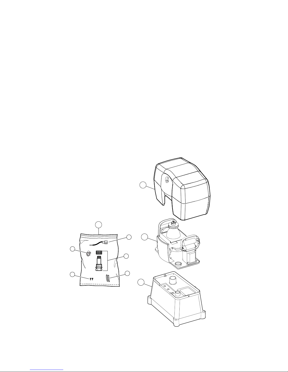
Introduction
1
3
2
4
a
b
c
d
e
1. Cover
2. Chassis Assembly
3. Installation Base
4. Parts Bag
a. Color wheel control plug
b. Manifold
c. 4" filler cables
d. Screws
e. Clamp
Polaris After Dark Complete
Page 4

Prepare the Conduit
Run separate conduits for each lens location. Use only sweep ells or heat-bent PVC, not
standard 90° plumbing fittings. Center the fiber optic conduits where the installation base will
be placed.
Remove the cover and separate the chassis assembly from the installation base. Using the
handles, lift the chassis off the base and place it in a safe location until ready to complete
electrical connections.
Cut the conduit so it protrudes 1/3 of the way into the installation base.
Guide the electrical conduit through the small hole in the installation base until it extends
1" to 4" above the base.
www.polarispool.com
Installation Instructions
1
Fiber Optic Conduit
Pool
Fiber
Conduit
Light Driver
Installation Base
Final
Ground
Elevation
Side View
Electrical Conduit
Page 5

Install the Base
If installing underwater lights, install the Universal Fiber Lens (part #AD10) first and then
install the light driver. If installing a light kit, install the fiber first and then install the light driver.
Remove the installation base to access conduit ends.
1. Feed the fiber optic cable through the conduits. Measure enough cable for a service loop
of at least 18" but no more than 36" at the light driver.
2. Strip the fiber casing back 8-10" to expose the bare fibers. Hold the tips of the fiber
cables even and insert them through the fiber manifold body starting at the compression
fitting. Push the fiber through until the bare fibers extend 3-4” past the manifold opening.
3. Secure the loose fibers with the clamp provided, making sure that the individual fibers
extend at least 1” beyond the clamp. Use the Polaris Hot Knife (part #AD25) to trim the
fibers until the ends are clean and even with the clamp.
4. Remove the clamp and slide the fibers back so that they are flush with the
manifold opening.
5. Hand tighten the compression fitting. If the fitting does not hold the fiber casings securely,
loosen the fitting, insert the filler cables provided and re-tighten the fitting.
www.polarispool.com
2
Polaris Hot Knife
Fiber Manifold
Clamp
1"
Fiber Manifold
Position Fiber tips Even with
End of Fiber Manifold
Loose Fibers
Fiber Optic Cables
Page 6

6. Insert the fiber manifold into the installation base from the bottom and secure it at the top
with the manifold nut.
7. Place the installation base over the ends of the fiber optic conduits while guiding the
electrical conduit through the smaller hole.
8. Backfill dirt around the installation base to secure it. Ground level should be at least 1"
below the top of the base.
www.polarispool.com
Installation Base
Fiber Manifold
Fiber Optic
Cables
Manifold Nut
Side View
Installation Base
1" below
top of base
Fill dirt line
Page 7

Install Chassis Assembly
Using the handles, lift the chassis assembly onto the installation base and secure.
To connect the electrical supply, check the model number of your light driver and refer to the
wiring connection requirements below for the proper configuration.
Position and secure the cover onto the installation base/chassis assembly.
www.polarispool.com
3
Model AD150, manual control light driver.
Model AD151, white light only light driver.
Model AD150, remotely controlled by Polaris
Sol 1000 or another external control system.
Main Power
120VAC
(Black)
Neutral
(White)
Ground
(Green)
Connect to incoming power
(Discard
this plug )
Main Power, Aux 1
120VAC (Black)
Neutral
(White)
Ground
(Green)
Connect to incoming power
(Install Color Wheel
Control plug)
Color Wheel Control, Aux 2
120VAC (Red)
Main Power
120VAC
(Black)
Ground
(Green)
Neutral
(White)
Connect to incoming power
Screws
Ground Level
Installation Base
(Buried)
Page 8

Power Switches
The switch plate controls power
and light. If you have model AD151
which emits white light only, there
will be no color wheel switch.
When turned on, the cooling fan
will engage and the indicator light
on the power switch will glow. Due to
the nature of the metal-halide lamp
system, the fiber optic light will get
brighter gradually; it may take up to
two minutes to reach full intensity.
If using a Polaris Sol controller or
any other external remote control
system, leave the power switch on
at all times. The power to the light
driver will be activated by the
external remote control.
Color Wheel Settings
(Model AD150)
The color wheel switch has three positions: STOP, FAST and SLOW.
STOP: the color wheel stays on one color
FAST: the color wheel rotates quickly (1 RPM) and the colors change every 6.5 seconds.
SLOW: the color wheel rotates slowly (1/2 RPM) and the colors change approximately every
13 seconds.
Activation of the color wheel can be controlled by a Polaris Sol controller or another remote
control system; however, the rotation speed of the color wheel can only be changed manually
at the light driver control panel.
www.polarispool.com
Operation
AD150 Control Panel. Light Driver With Color Wheel
Power
POWER
ON
OFF
AD151 Control Panel. Light Driver With No Color Wheel
Powe r
POWER
ON
OFF
COLOR
COLOR
Color Wheel
Switch
FAST
STOP
SLOW
Blank Insert or
Non-operational
Switch
FAST
STOP
SLOW
Page 9

1
9
10
2
3
4
5
6
7
8
11
12
13
14
15
16
17
18
Parts Bag
Components
www.polarispool.com
1 AD210 Cover 1
2 AD300 Lamp/Reflector Assembly 1
3 AD305 Lamp Only, 150W H.I.D 1
4 AD310 Lamp Bracket 1
5 AD325 Lamp Wire/Socket Assembly 1
6 AD320 Heat Filter Assembly 1
7 AD435 Fuse, Color Wheel 1
8 AD430 Color Wheel Control Board 1
9 AD640 Fuse Holder, Main Power 1
10 AD650 Fuse, Main Power 1
11 AD410 Color Wheel Retainer 1
12 AD400 Color Wheel Assembly 1
13 AD630 Fan 1
14 AD620 Switch, Color wheel Power 3-way 1
15 AD610 Switch, Main Power 2-way 1
16 AD420 Color Wheel Motor 1
17 AD500 Color Wheel Power Connector 1
18 AD100 Manifold Assembly 1
AD10 UFL Waterproof Lens Housing,
Universal, 1-1/2" MIP
AD15 Wireless Remote
No. Part Description Qty
AfterDark
Exploded Parts Diagram
Page 10

www.polarispool.com
If the Polaris After Dark displays any of the
following actions, adjustments may be
necessary to restore performance. Refer to
the exploded parts diagram for part
numbers indicated in parenthesis.
Action: The light driver does not come on.
Solution: 1. Verify that unit is turned on.
2. If using an external remote
controller to activate the
120VAC supply, make sure
that the relay controlling the
light driver is on and
supplying power.
3. Locate the Ground Fault
Circuit Interrupter (G.F.C.I.)
protecting the circuit and
verify proper operation by
following the Test and Reset
instructions on the G.F.C.I.
4. Verify that the in-line fuse (#8),
located on the chassis, is intact.
Action: The color wheel does not rotate.
Solution: 1. Verify that the color switch
is positioned for slow or
fast operation.
2. If using a Polaris Sol
controller or other external
remote controller, make sure
the relay controlling it is on
and supplying power.
3. Check the spade connectors
on the color wheel circuit
board (#7) and verify that they
are connected properly.
Action: The light output has dimmed
over time.
Solution: 1. Turn off the power to the light
driver and check for dirt build
up on the manifold tip, color
wheel, and heat filter. Clean
as necessary.
2. Check the universal fiber lens
to make sure it is not filled
with water.The area around
the fiber tip inside the lens
must be dry.
Action: The light driver is turned on but
it continues to cycle on and off.
Solution: 1. With the unit operating, listen
for the cooling fan (#13). If it is
not heard, it may be blocked.
Turn off the main power to the
light driver, remove the cover,
clear the fan of any debris
and check its wiring.
Troubleshooting
Page 11

www.polarispool.com
Polaris After Dark Light Driver Limited Warranty
This limited warranty is extended to the original consumer purchaser of this Polaris After Dark light driver
manufactured by Polaris Pool Systems, Inc., 2620 Commerce Way, Vista, California 92083-8438, USA.
Polaris warrants the light driver it manufactures, including all parts and components thereof, to be free of
defects in material and workmanship. We do not cover improper installation of the Polaris After Dark light
driver or fiber optic cable but our instruction manual is complete enough to solve any problems — particularly
if it is read before, rather than after, the installation. If you have any questions regarding your Polaris After
Dark product, please feel free to call or write us. Be sure to include the serial number of your unit.
The warranty commences on the date of installation of the Polaris After Dark light driver. The Polaris After
Dark light driver parts are warranted for a period of one year. Polaris will not be responsible for any damage to
non-Polaris fiber optic cable. This Polaris After Dark light driver is designed to work only with genuine Polaris
fiber optic cable.
This limited warranty does not apply if the failure is caused by or contributed to any of the following: improper
handling, improper storage, winter freezing, abuse, improper installation, unsuitable application of the unit,
lack of reasonable and necessary maintenance, or repairs made or attempted by other than Polaris or one of
its Authorized Service Centers. Polaris will repair or replace, at its option, a unit or part proved to be defective
within the warranty period and under the conditions of the warranty.
Polaris is not responsible for the cost of removal of the unit or part, damages due to removal, or any other
expenses incurred in shipping the unit or part to or from the factory or its Authorized Service Centers, or the
installation of the repaired or replacement unit. The consumer must bear these expenses.
This warranty does not cover repair or replacement of a unit or part except at our factory or a Polaris
Authorized Service Center.
THIS LIMITED WARRANTY IS IN LIEU OF ALL OTHER WARRANTIES, EXPRESS OR IMPLIED,
INCLUDING THE IMPLIED WARRANTIES OF MERCHANTABILITY AND FITNESS FOR A PARTICULAR
PURPOSE, AND ALL SUCH OTHER WARRANTIES ARE DISCLAIMED EXCEPT TO THE EXTENT ANY
IMPLIED WARRANTY MAY BE IMPOSED BY STATE CONSUMER LAW. ANY SUCH IMPLIED WARRANTY
IMPOSED BY STATE CONSUMER LAW IS LIMITED IN DURATION TO ONE (1) YEAR FROM DATE OF
PURCHASE.IN NO EVENT SHALL POLARIS BE LIABLE FOR INCIDENTAL OR CONSEQUENTIAL
DAMAGES OF ANY NATURE OR KIND OR FOR DAMAGES TO PERSONS OR PROPERTY.
Some states do not allow limitations on how long an implied warranty lasts, or the exclusion or limitation of
incidental or consequential damages, so the above limitations may not apply to you.
This limited warranty is valid only in the United States of America, Canada and Australia, and it does not apply
to Polaris After Dark light drivers sold or installed in any other country.
Model Specifications
Model: AD150 (Colored Light) Model: AD151 (White Light)
Lamp Type: Metal-Halide Lamp, CDM Lamp Type: Metal-Halide Lamp, CDM
Replacement Lamp P/N: AD300 Replacement Lamp P/N: AD300
Colors: 9 No Colors
C/W Motor: 12 VDC, 2 speeds No Color Wheel Motor
Voltage: 120 VAC, 60 HZ Voltage: 120 VAC, 60HZ
Power Consumption: 200 Watts Max Power Consumption: 200 Watts Max
Start Current Load: 4.4 Amps Start Current Load: 4.4 Amps
Run Current Load: 1.8 Amps Run Current Load: 1.8 Amps
Enclosure Material: Luran®S ASA Enclosure Material: Luran®S ASA
Ventilation: 110 cu. ft./min. Ventilation: 110 cu. ft./min.
Weight: 21 lbs. Weight: 20 lbs.
Page 12

©2004 Polaris Pools Systems, Inc. All Rights Reserved. TL-600 1/04
 Loading...