

Page 1
GENERAL INFORMATION
Model Identification 1.2.......................
Serial Number Location 1.2...................
Replacement Keys 1.3.......................
Publication Numbers 1.3.....................
Paint Codes 1.3.............................
Specifications 1.4--1.5...........................
Standard Torque Specifications 1.6............
Tap Drill Charts 1.7..........................
Specs
Decimal Equivalent Chart 1.7.................
Unit of Measure Conversion Table 1.8..........
Glossary of Terms 1.9--1.10........................
1.1
Page 2

GENERAL INFORMATION
MODEL IDENTIFICATION
The machine model number must be used with any correspondence regarding warranty or service.
Machine Model Number Identification
A09BG50AA
Emissions &
Year Designation
Basic Chassis
Designation Engine Designation
Model Option
ENGINE DESIGNATION NUMBERS
EH500PLE Single, Liquid Cooled, SOHC 4 Stroke, Electric Start.................
VIN IDENTIFICATION
World Mfg. ID
1 2 3 4 5 6 7 8 9 10 11 12 13 14 15 16 17
4XABA
Vehicle Descriptor
50A* P000000
9
Vehicle Identifier
Body Style
Powertrain
Emissions
Engine
Check Digit
Model
Year
Plant No.
Individual Serial No.
* This could be either
a number or a letter
ENGINE SERIAL NUMBER LOCATION
Whenever corresponding about a vehicle, be sure to refer to the engine model number and serial number. This
information can be found on the sticker applied to the recoil housing on the right side of engine.(A) An additional
number is stamped on the center top of crankcase beneath the cylinder coolant elbow.
UNIT MODEL NUMBER AND SERIAL NUMBER LOCATION
Themachinemodelnumber andserialnumberare
important for vehicle identification. The machine
serial number is stamped on the lower left side of
the frame tube.(B)
A
Front
B
TRANSMISSION I.D. NUMBER
LOCA
TION
1.2
The transmission I.D. number is located
on top of the transmission, right side of
machine.
Page 3
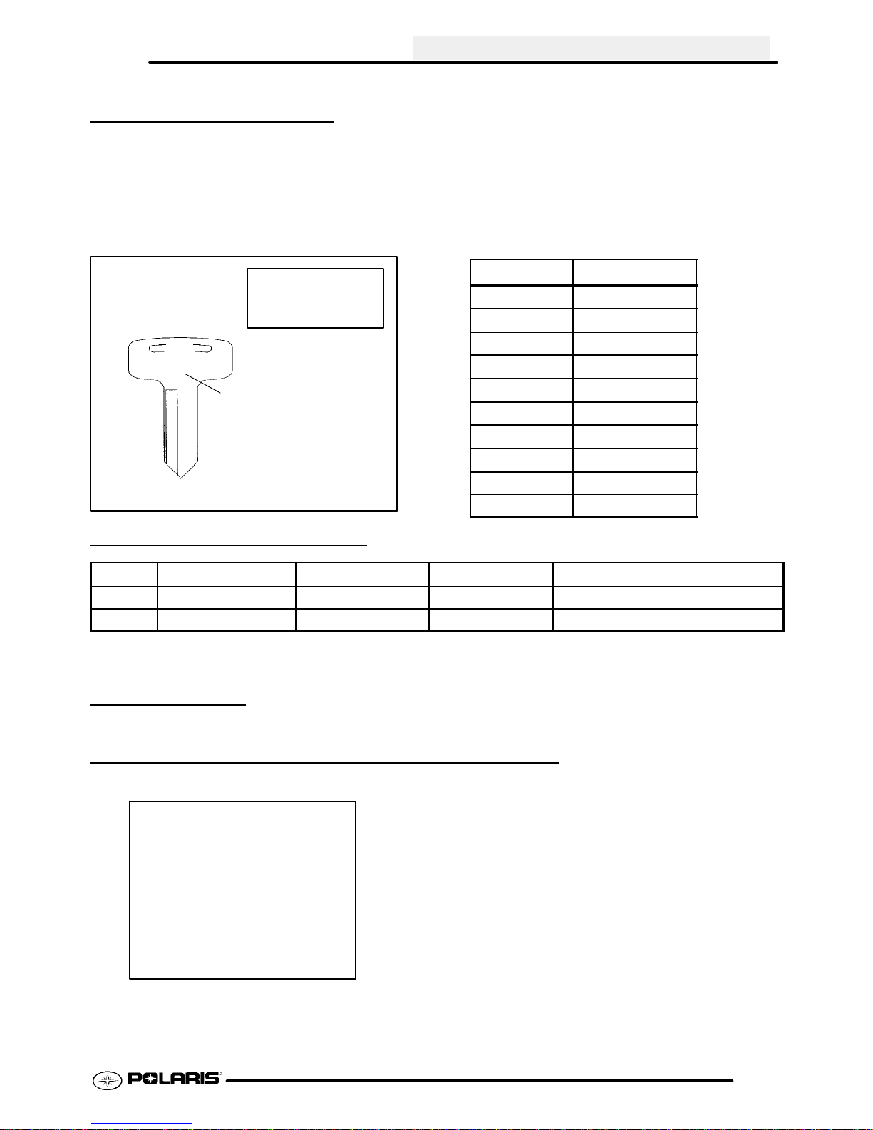
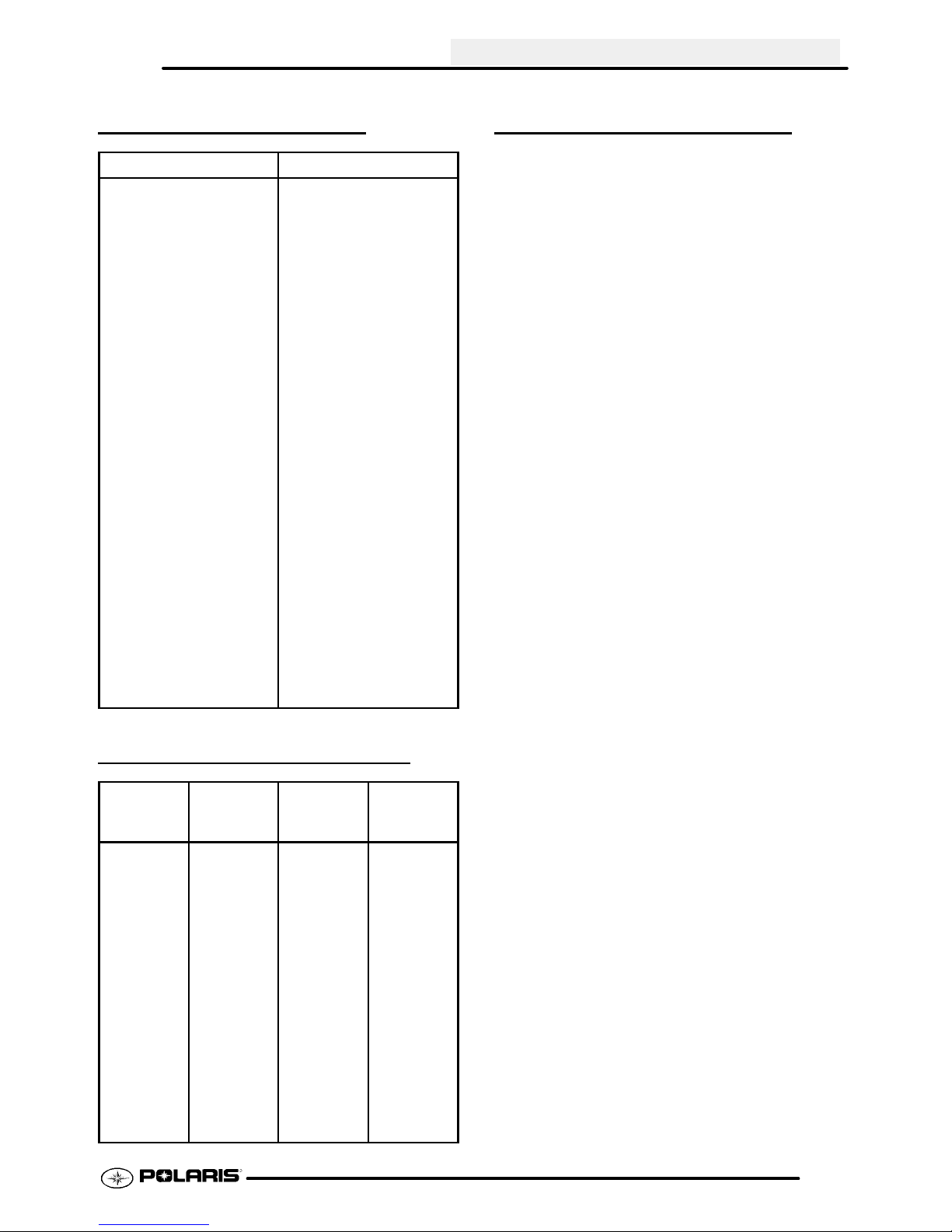
REPLACEMENT KEYS
Replacement keys can be made from the original
key. To identify which series the key is, take the
first two digits on the original key and refer to the
chart to the right for the proper part number.
Shouldbothkeysbecomelost, ignition switch
replacement is required.
GENERAL INFORMATION
Series # Part Number
20 4010278
21 4010278
22 4010321
23 4010321
27 4010321
28 4010321
31 4110141
32 4110148
67 4010278
68 4010278
31XX
KEY COVER
P/N 5433534
Key Series
Number
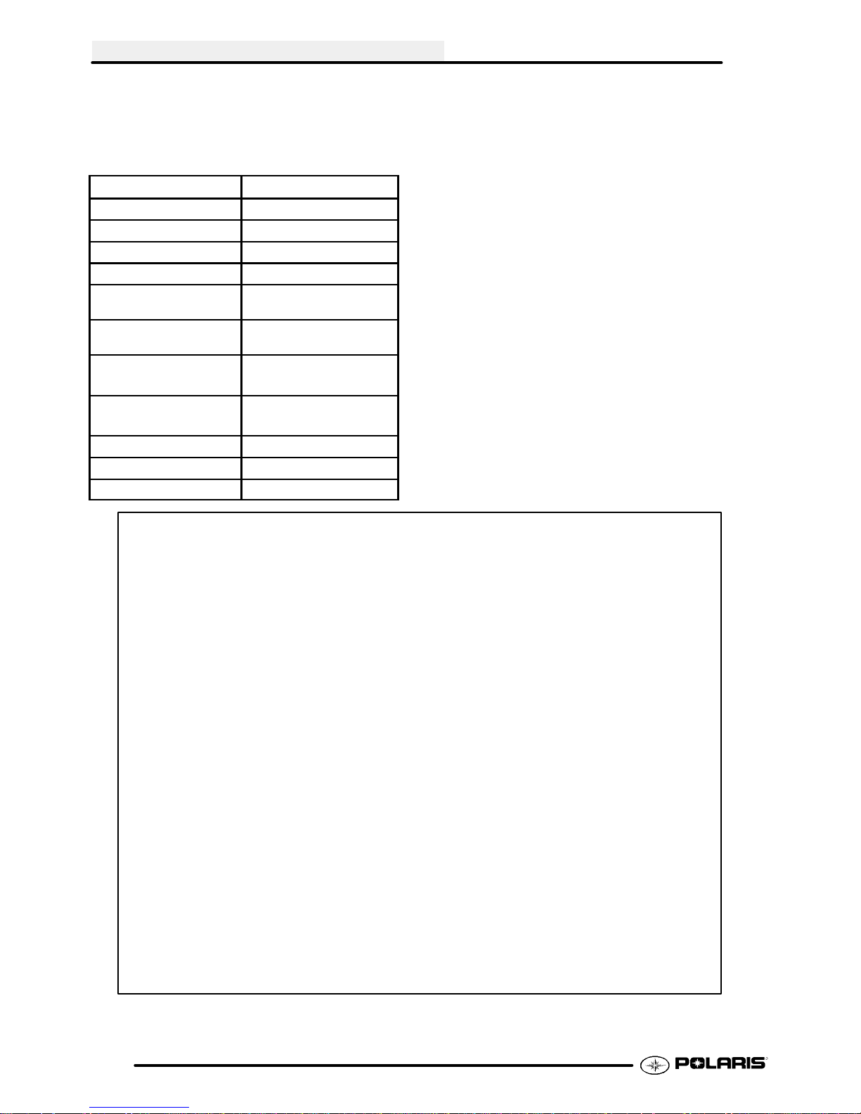
PUBLICATION NUMBERS
Year Model Model No. Owner’s Manual Parts Manual
2009 Scrambler500 4x4 A09BG50AA, FA 9921777 9921778
2009 Scrambler500 2x4 A09BA50FA 9921777 9921778
When ordering service parts be sure to use the correct parts manual.
PAINT CODES
FRAME COLOR - (All) P067 Medium Gloss Black 9440 / 8520147.
COLD WEATHER KITS FOR 4 CYCLE ATVS
Engine Heater -- (PN 2871507)
ACCESSORY ENGINE HEATER
1.3
Page 4
GENERAL INFORMATION
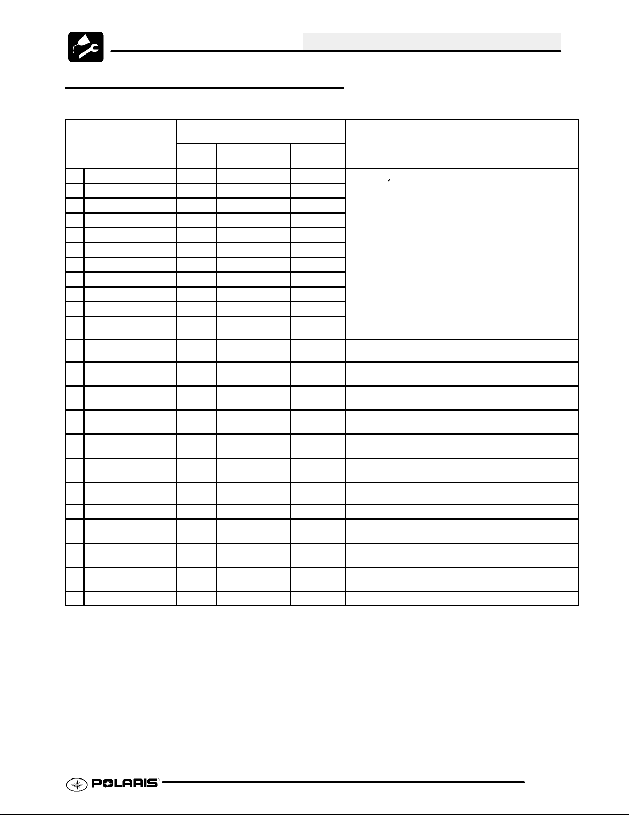
MODEL: 2009 SCRAMBLER 500..........
MODEL NUMBER: A09BG50AA, FA / A09BA50FA.
( 4x4 / Intl’ ) (2x4 Intl’)
ENGINE MODEL: EH50PLE..
Category
Length 75 in./190.5 cm
Width 46 in./116.8 cm
Height 47 in./119.4 cm
Wheel Base 48 in./121.9 cm
Dry Weight 571 lbs./259 kg (4x4)
Gross Vehicle Weight 845 Lbs. / 383 kg (4x4)
Front Rack Capacity
(Accessory)
Rear Rack Capacity
(Accessory)
Tow Capacity 850 lbs./385.9 kg
Tongue Weight 85 lbs./38.6 kg
Body Style Gen III
Dimension / Capacity
571 lbs./259 kg (2x4)
845 Lbs. / 383 kg (2x4)
30 lbs./13.6 kg
60 lbs./27.2 kg
1.4
NOTE: 4x4 Model Shown
Page 5
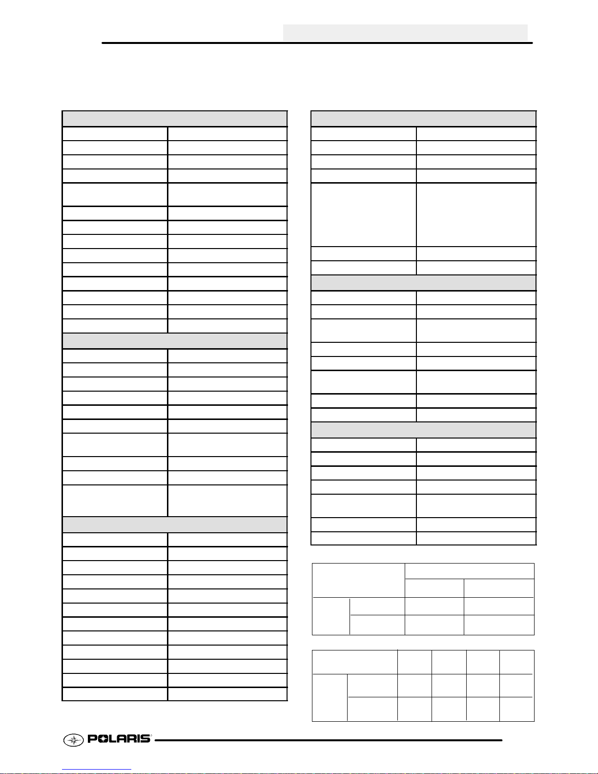
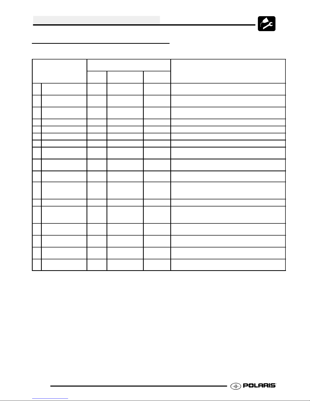
MODEL: 2009 SCRAMBLER 500..........
MODEL NUMBER: A09BG50AA, FA / A09BA50FA.
ENGINE MODEL: EH50PLE..
Engine
Platform Fuji Single Cylinder
Engine Model Number EH500PLE
Engine Displacement 499cc
Number of Cylinders 1
Bore & Stroke 92 x 75 mm
3.6248I x 2.955I
CompressionRatio 10.2:1
Compression Pressure 70--90 psi w/decompressor
Engine Idle Speed 1200Rpm ± 100
Engine Max Operating Rpm 6500 Rpm ± 200
Cooling System / Capacity Liquid -- 2.25 qt / 2.1 ltr
Overheat Warning HOT Indicator
Lubrication PressurizedDry Sump
Oil Requirements / Capacity Polaris 0W--40 2 qt. / 1.9 ltr
Exhaust System Single Pipe
Carburetion
Carburetor model Mikuni BST 40mm
Main Jet 155
Pilot Jet 40
Pilot Air Jet 160
Jet Needle -- Clip Position 6H25--94--3
Needle Jet Y--0M (896)
Pilot Screw 2 Turns Out
(Set at factory, will vary on each vehicle)
Float Height 13 ± 1 mm / 0.51 ± 0.40“
Fuel Delivery Fuel Pump
Fuel Capacity / Requirement 3.5 gal US / 13.2 ltr
87 Octane (minimum)
89 Oxygenated
Electrical
Alternator Output 250 w @ 5000 RPM
Voltage Regulator 3--Phase-- LR--39
Lights : Head(Twin) 30 / 30 watts
Brake 8.26 watts
Tail 26.9 watts
Ignition System CDI Ignition
RPM Limit 6600 RPM
Ignition Timing 30° BTDC @ 5000 RPM ± 250
Spark plug / Gap BKR6E/ .036 in./0.9 mm
Battery / Model / Amp Hr Low Maintenance 14 Amp Hr
Circuit Breakers Solid State in PDM
Starting Electric
GENERAL INFORMATION
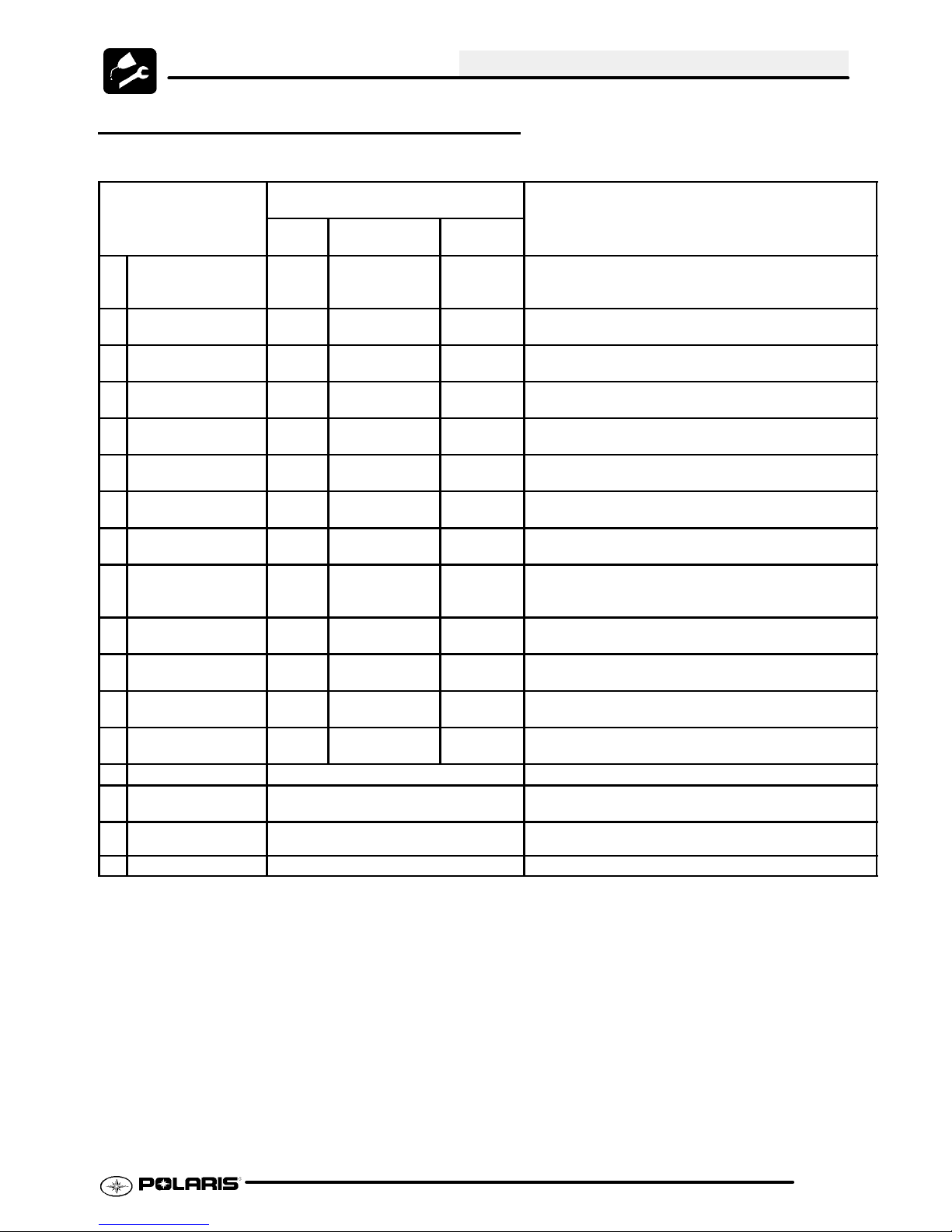
Drivetrain
Transmission Type H/N/Rev
Transmission Capacity 32oz. / 945ml
Front AWD Hub Capacity 2.5 oz. / 75ml
Front Gearcase Capacity 4oz./118ml
Gear Ratio : Low
Rev
High
Front Drive
Rear Drive / Chain Pitch
Chain Type 520 O--ring
PVT Type / Belt Non--EBS / 3211091
Steering / Suspension
Front Suspension / Shock A--arm / MacPherson Strut
Front Travel 8.2 in. / 20.83 cm
Rear Suspension / Shock Progressive Rate Swing Arm
Twin Tube Gas Charged
Rear Travel 10.5 in. / 26.67 cm
Ground Clearance 5.5 in. / 13.97 cm
Shock Preload Adjustment
Front / Rear
Front --Non Adjustable.
Rear -- Cam Adjuster
Turning Radius 83 in. / 210.8 cm unloaded
Toe Out 1/8 -- 1/4 in / 3 -- 6.35 mm
Wheels / Brakes
Wheel Size / Pattern -- Front Steel 23x7--10 / 4--156
Wheel Size / Pattern -- Rear Steel 22x11--10 / 4--102
Front Tire Size 23x7--10
Rear Tire Size 22x11--10
Recommended Air Pressure
F/R
Brake -- Front Dual Hydraulic Disc
Brake -- Rear Single Hydraulic Disc
JETTING CHART
AMBIENT TEMPERATURE
Below 40°F
Below 5°C
160
152.5
Meters
(Feet)
Altitude
(0--6000)
above 1800
(above 6000)
0--1800
CLUTCH CHART
Shift
Weight
10 WH
PN 5630710
10 RH
PN 5630709
Spring
Blu/Grn
PN 7041157
Blu/Grn
PN 7041157
Meters
(Feet)
Altitude
0--1800
(0--6000)
1800--3700
(6000--12000)
n/a
4.74:1
3.06:1
2:1
13/36 76 Pitch
4 psi Front
3 psi Rear
+40°Fto+80°F
Drive
Driven
Spring
Silver
PN 7041499
Silver 1--1
PN 7041499
+5°Cto+28°C
155
147.5
Driven
Helix
40_
PN 5131446
40_
PN 5131446
1--1
1.5
Page 6
GENERAL INFORMATION
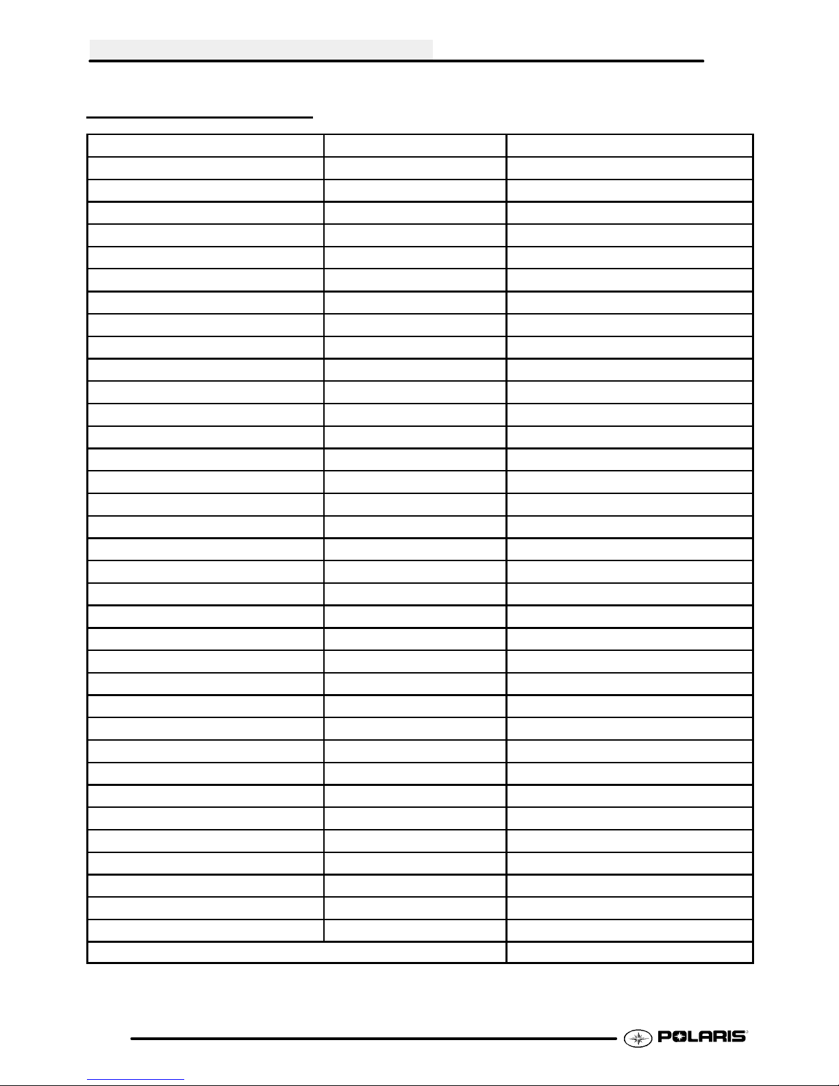
STANDARD TORQUE SPECIFICATIONS
Thefollowing torquespecificationsare tobeused as a generalguideline. FOR SPECIFICTORQUE VALUESOF
FASTENERS Refer to exploded views in the appropriate section. There are exceptions in the steering,
suspension, and engine sections.
Bolt Size Threads/In Grade 2 Grade 5 Grade 8
T orque in. lbs. (Nm)
#10 - 24 27 (3.1) 43 (5.0) 60 (6.9).............. ................ ..............
#10 - 32 31 (3.6) 49 (5.6) 68 (7.8).............. ................ ..............
T o rque ft. lbs. (Nm)*
1/4 - 20 5 (7) 8 (11) 12 (16).............. .................. ................
1/4 - 28 6 (8) 10 (14) 14 (19).............. .................. ..............
5/16 - 18 11 (15) 17 (23) 25 (35).............. ................ ..............
5/16 - 24 12 (16) 19 (26) 29 (40).............. ................ ..............
3/8 - 16 20 (27) 30 (40) 45 (62).............. ................ ..............
3/8 - 24 23 (32) 35 (48) 50 (69).............. ................ ..............
7/16 - 14 30 (40) 50 (69) 70 (97).............. ................ ..............
7/16 - 20 35 (48) 55 (76) 80 (110).............. ................ ..............
1/2 - 13 50 (69) 75 (104) 110 (152).............. ................ .............
1/2 - 20 55 (76) 90 (124) 120 (166).............. ................ .............
Metric
6 x 1.0 72-78 In. lbs. 8 x 1.25 14-18 ft. lbs. 10 x 1.25 26-30 ft. lbs..... ......
1.6
Page 7
GENERAL INFORMATION
SAE TAP DRILL SIZES
Thread Size/Drill Size Thread Size/Drill Size
#0-80 3/64
#1-64 53
#1-72 53
#2-56 51
#2-64 50
#3-48 5/64
#3-56 45
#4-40 43
#4-48 42
#5-40 38
#5-44 37
#6-32 36
#6-40 33
#8-32 29
#8-36 29
#10-24 24
#10-32 21
#12-24 17
#12-28 4.6mm
1/4-20 7
1/4-28 3
5/16-18 F
5/16-24 I
3/8-16 O
3/8-24 Q
7/16-14 U
7/16-20 25/64
1/2-13 27/64
1/2-20 29/64
9/16-12 31/64
9/16-18 33/64
5/8-11 17/32
5/8-18 37/64
3/4-10 21/32
3/4-16 11/16
7/8-9 49/64
7/8-14 13/16
1-8 7/8
1-12 59/64
1 1/8-7 63/64
1 1/8-12 1 3/64
11/4-7 17/64
1 1/4-12 1 11/64
11/2-6 111/32
1 1/2-12 1 27/64
13/4-5 19/16
1 3/4-12 1 43/64
2-4 1/2 1 25/32
2-12 1 59/64
2 1/4-4 1/2 2 1/32
21/2-4 21/4
23/4-4 21/2
3-4 2 3/4
METRIC TAP DRILL SIZES
Tap Size Drill Size Decimal
Equiva-
lent
3x.50
3x.60
4x.70
4x.75
5x.80
5x.90
6 x 1.00
7 x 1.00
8 x 1.00
8 x 1.25
9 x 1.00
9 x 1.25
10 x 1.25
10 x 1.50
11 x 1.50
12 x 1.50
12 x 1.75
#39
3/32
#30
1/8
#19
#20
#9
16/64
J
17/64
5/16
5/16
11/32
R
3/8
13/32
13/32
0.0995
0.0937
0.1285
0.125
0.166
0.161
0.196
0.234
0.277
0.265
0.3125
0.3125
0.3437
0.339
0.375
0.406
0.406
Nearest
Fraction
3/32
3/32
1/8
1/8
11/64
5/32
13/64
15/64
9/32
17/64
5/16
5/16
11/32
11/32
3/8
13/32
13/32
DECIMAL EQUIVALENTS
1/64 .0156................
1/32 .0312 1 mm = .0394″........... ...
3/64 .0469................
1/16 .0625...........
5/64 .0781 2 mm = .0787″................ ...
3/32 .0938...........
7/64 .1094 3 mm = .1181″.............. ...
1/8. .1250...
9/64 .1406................
5/32 .1563 4 mm = .1575″........... ...
11/64 .1719...............
3/16 .1875 5 mm = .1969″........... ...
13/64 .2031...............
7/32 .2188...........
15/64 .2344 6 mm = .2362″............... ...
1/4 .25....
17/64 .2656 7 mm = .2756″............... ...
9/32 .2813...........
19/64 .2969...............
5/16 .3125 8 mm = .3150″........... ...
21/64 .3281...............
11/32 .3438 9 mm = .3543″.......... ...
23/64 .3594...............
3/8 .375....
25/64 .3906 10 mm = .3937″............... ...
13/32 .4063.........
27/64 .4219 11 mm = .4331″............... ...
7/16 .4375...........
29/64 .4531...............
15/32 .4688 12 mm = .4724″......... ...
31/64 .4844...............
1/2 .5 13 mm = .5118.... ..............
33/64 .5156...............
17/32 .5313.........
35/64 .5469 14 mm = .5512″............... ...
9/16 .5625...........
37/64 .5781 15 mm = .5906″............... ...
19/32 .5938.........
39/64 .6094...............
5/8 .625 16 mm = .6299″.... ............
41/64 .6406...............
21/32 .6563 17 mm = .6693″......... ...
43/64 .6719..............
11/16 .6875..........
45/64 .7031
23/32 .7188.........
47/64 .7344 19 mm = .7480″............... ...
3/4 .75....
49/64 .7656...............
25/32 .7813 20 mm = .7874″......... ...
51/64 .7969...............
13/16 .8125 21 mm = .8268″......... ...
53/64 .8281...............
27/32 .8438.........
55/64 .8594 22 mm = .8661″............... ...
7/8 .875....
57/64 .8906 23 mm = .9055″............... ...
29/32 .9063.........
59/64 .9219..............
15/16 .9375 24 mm = .9449″......... ...
61/64 .9531...............
31/32 .9688 25 mm = .9843......... ...
63/64 .9844...............
11.0.....
18 mm = .7087″............... ...
1.7
Page 8
GENERAL INFORMATION
CONVERSION TABLE
Unit of Measure Multiplied by Converts to
ft. lbs. x12 =in.lbs.
in. lbs. x .0833 = ft. lbs.
ft. lbs. x 1.356 =Nm
in. lbs. x .0115 =kg-m
Nm x .7376 = ft.lbs.
kg-m x 7.233 = ft. lbs.
kg-m x 86.796 =in.lbs.
kg-m x10 =Nm
in. x 25.4 =mm
mm x .03937 =in.
in. x2.54 =cm
mile (mi.) x1.6 =km
km x .6214 = mile (mi.)
Ounces (oz) x 28.35 = Grams (g)
Fluid Ounces (fl. oz.) x 29.57 = Cubic Centimeters (cc)
Cubic Centimeters (cc) x .03381 = Fluid Ounces (fl. oz.)
Grams (g) x 0.035 = Ounces (oz)
lb. x .454 =kg
kg x 2.2046 =lb.
Cubic inches (cu in) x 16.387 = Cubic centimeters (cc)
Cubic centimeters (cc) x 0.061 = Cubic inches (cu in)
Imperial pints (Imp pt) x 0.568 = Liters (l)
Liters (l) x1.76 = Imperial pints (Imp pt)
Imperial quarts (Imp qt) x 1.137 = Liters (l)
Liters (l) x0.88 = Imperial quarts (Imp qt)
Imperial quarts (Imp qt) x 1.201 = US quarts (US qt)
US quarts (US qt) x 0.833 = Imperial quarts (Imp qt)
US quarts (US qt) x 0.946 = Liters (l)
Liters (l) x 1.057 = US quarts (US qt)
US gallons (US gal) x 3.785 =Liters (l)
Liters (l) x 0.264 = US gallons (US gal)
Pounds - force per square inch (psi) x 6.895 = Kilopascals (kPa)
Kilopascals (kPa) x 0.145 = Pounds - force per square inch (psi)
Kilopascals (kPa) x0.01 = Kilograms - force per square cm
Kilograms - force per square cm x 98.1 = Kilopascals (kPa)
π (3.14) xR2x H (height) = Cylinder Volume
°Cto°F: 9 (°C + 40) ÷ 5-40=°F
°Fto°C: 5 (°F + 40) ÷ 9-40=°C
1.8
Page 9

GENERAL INFORMATION
GLOSSARY OF TERMS
ABDC: After bottom dead center.
ACV: Alternating current voltage.
Alternator: Electrical generator producing voltage alternating current.
ATDC: After top dead center.
BBDC: Before bottom dead center.
BDC: Bottom dead center.
BTDC: Before top dead center.
CC: Cubic centimeters.
Center Distance: Distance between center of crankshaft and center of driven clutch shaft.
Chain Pitch: Distance between chain link pins (No. 35 = 3/8″ or 1 cm). Polaris measures chain length in number of
pitches.
CI: Cubic inches.
Clutch Buttons: Plastic bushings which transmit rotation of the clutch to the movable sheave in the drive and driven
clutch.
ClutchOffset: Drive and drivenclutchesareoffsetso thatdrivebelt will stay nearlystraightasit movesalongtheclutch
face.
Clutch Weights: Three levers in the driveclutch which relative to theirweight, profile and engine RPMcause thedrive
clutch to close.
Condenser/Capacitor: A storage reservoir for DC voltage.
Crankshaft Run-Out: Run-out or “bend” of crankshaft measured with a dial indicator while crankshaft is supported
between centers on V blocks or resting in crankcase. Measure at various points especially at PTO.
DCV: Direct current voltage.
Dial Bore Gauge: A cylinder measuring instrument which uses a dial indicator. Good for showing taper and
out-of-round in the cylinder bore.
Electrical Open: Open circuit. An electrical circuit which isn’t complete.
Electrical Short: Short circuit. Anelectrical circuit which is completed before the current reaches the intended load.
(i.e. a bare wire touching the chassis).
End Seals: Rubber seals at each end of the crankshaft.
Engagement RPM: Engine RPM at which the drive clutch engages to make contact with the drive belt.
ft.: Foot/feet.
Foot Pound: Ft. lb. A force of one pound at the end of a lever one foot in length, applied in a rotational direction.
g: Gram. Unit of weight in the metric system.
gal.: Gallon.
HP: Horsepower.
ID: Inside diameter.
in.: Inch/inches.
Inch Pound: In. lb. 12 in. lbs. = 1 ft. lb.
2
kg/cm
kg-m: Kilogram meters.
Kilogram/meter: A force of one kilogram at the end of a lever one meter in length, applied in a rotational direction.
lorltr: Liter .
lbs/in
Left Side: Always referred to based on normal operating position of the driver.
: Kilograms per square centimeter.
2
: Pounds per square inch.
1.9
Page 10

GENERAL INFORMATION
GLOSSARY OF TERMS
m: Meter/meters.
Mag: Magneto.
Magnetic Induction: As a conductor (coil) is moved through a magnetic field, a voltage will be generated in the
windings. Mechanical energy is converted to electrical energy in the stator.
mi.: Mile/miles.
mm: Millimeter. Unit of length in the metric system. 1mm = approximately .040″.
Nm: Newton meters.
OD: Outside diameter .
Ohm: The unit of electrical resistance opposing current flow.
oz.: Ounce/ounces.
Piston Clearance: Total distance between piston and cylinder wall.
psi.: Pounds per square inch.
PTO: Power take off.
PVT: Polaris Variable Transmission (Drive Clutch System)
qt.: Quart/quarts.
Regulator: Voltage regulator. Regulates battery charging system output at approx. 14.5 DCV as engine RPM
increases.
Reservoir T ank: Thefill tank in the liquid cooling system.
Resistance: Inthemechanicalsense,frictionorload. Intheelectricalsense, ohms. Bothresult inenergyconversionto
heat.
Right Side: Always referred to based on normal operating position of the driver.
RPM: Revolutions per minute.
Secondary Clutch: Driven clutch on chaincase or jackshaft.
SeizedPiston: Gallingofthesidesof a piston. Usuallythereis a transferofaluminumfromthe pistonontothecylinder
wall. Possible causes: 1) improper lubrication; 2)excessive temperatures; 3)insufficient piston clearance; 4) stuck
piston rings.
Stator Plate: The plate mounted under the flywheel supporting the battery charging coils.
TDC: Top dead center. Piston’s most outward travel from crankshaft.
Volt: The unit of measure for electrical pressure of electromotive force. Measured by a voltmeter in parallel with the
circuit.
Watt: Unit of electrical power. Watts = amperes x volts.
WOT: Wide open throttle.
1.10
Page 11
Periodic Maintenance Chart 2.2-2.5...............
Lubricant and Maintenance Product Numbers 2.6
Pre-Ride Inspection 2.7......................
Pure Polaris Products for Your ATV 2.8.........
Lubrication Charts 2.9-2.11........................
Front Gearcase Lubrication 2.11................
Transmission Lubrication 4x4 2.12..............
MAINTENANCE
Transmission Linkage Adjustment (H/L/R) 2.13-2.14...
Throttle Operation / Choke Adjustment 2.14......
Carburetor Adjustments 2.14--2.16...................
ETC Switch Operation 2.16-2.17....................
Fuel System 2.17-2.18.............................
Compression Test 2.19........................
Battery Maintenance 2.19-2.21......................
Electrical 2.21-2.22................................
Coolant System Maintenance 2.23..............
Air Filter Service 2.24--2.25.........................
Air Box Sediment Tube Service 2.25............
Breather Filter 2.25...........................
Recoil Housing 2.26...........................
PVT Drying 2.26............................
Oil Change/Filter 2.26-2.29.........................
Valve Clearance 2.29-2.30.........................
Steering and Toe Alignment 2.30-2.32...............
Front Hub Maintenance (AWD Models) 2.32--2.33.....
Exhaust System Maintenance 2.33--2.34.............
Brake System Service 2.34-2.35....................
Drive Chain and Sprocket Service 2.35-2.36..........
Suspension Service / Controls 2.37-2.39.............
Wheel Removal / Installation 2.39-2.40...............
Tire Inspection 2.40...........................
2.1
Page 12

MAINTENANCE
PERIODIC MAINTENANCE CHART
Careful periodic maintenance will help keep your vehicle in the safest, most reliable condition. Inspection,
adjustment and lubrication of important components are explained in the periodic maintenance chart.
Inspect, clean, lubricate, adjust and replace parts as necessary. When inspection reveals the need for
replacement parts, use genuine Polaris parts available from your Polaris dealer.
NOTE: Service and adjustments are critical. If you’re not familiar with safe service and adjustment
procedures, have a qualified dealer perform these operations.
Maintenance intervals in the following chart are based upon average riding conditions and an average vehicle
speedofapproximately10 milesperhour. Vehiclessubjectedto severeuse mustbe inspectedandservicedmore
frequently.
Severe Use Definition
G Frequent immersion in mud, water or sand
G Racing or race-style high RPM use
G Prolonged low speed, heavy load operation
G Extended idle
G Short trip cold weather operation
Pay special attention to the oil level. A rise in oil level during cold weather can indicate contaminants collecting
in the oil sump or crankcase. Change oil immediately if the oil level begins to rise. Monitor the oil level, and if
it continues to rise, discontinue use and determine the cause or see your dealer.
Maintenance Chart Key
The following symbols denote potential items to be aware of during maintenance:
H= CAUTION: Due to the nature of these adjustments, it is recommended this service be performed
by an authorized Polaris dealer.
"= SEVERE USE ITEM ----If vehicle is subjected to severe use, decrease interval by 50%
(Severe Use is defined as frequent vehicle immersion in mud, water or sand, racing or race-style high rpm
use, prolonged low speed - heavy load operation or extended idle. More preventative maintenance is
required under these conditions. Fluid changes, cable, chain and chassis lubrication are required more
frequently. For engine oil, short trip cold weather riding also constitutes severe use. Pay special attention
to oil level. A rising oil level in cold weather can indicate contaminants collecting in the oil sump or
crankcase. Change oil immediately and monitor level. If oil level begins to rise, discontinue use and
determine cause.)
E= Emission Control System Service (California).
NOTE: Inspection may reveal the need for replacement parts. Always use genuine Polaris parts.
WARNING: Improperly performing the procedures marked with a
to serious injury or death. Have an authorized Polaris dealer perform these services.
J could result in component failure and lead
2.2
Page 13
MAINTENANCE AND LUBRICATION
j
Periodic Maintenance Chart
MAINTENANCE
Item Maintenance Interval
(whichever comes first)
Hours Calendar Miles
(Km)
J
Steering
"
Front suspension
"
Rear suspension
Tires
"
Brake fluid level
"
Brake lever travel
Brake systems
Drive Chain
Wheels/fasteners
Frame fasteners
"
Engine oil level
E
"
Air filter, pre-filter
E
"
Air box sediment
E
tube
Coolant
--
--
--
--
--
--
--
--
--
--
--
--
--
--
Pre-Ride
Pre-Ride
Pre-Ride
Pre-Ride
Pre-Ride
Pre-Ride
Pre-Ride
Pre-Ride
Pre-Ride
Pre-Ride
Pre-Ride
Daily
Daily
Daily
--
--
--
--
--
--
--
--
--
--
--
--
--
--
Make adjustments as needed.
Inspect; clean often
Drain deposits when visible
Check level daily, change coolant every 2 years
(if applicable)
Headlamp/tail
lamp
"
Air filter,
E
main element
Recoil housing
--
--
--
Daily
Weekly
Weekly
--
Check operation; apply dielectric grease if replacing
--
--
Inspect; replace as needed
Drain water as needed, check often if operating
in wet conditions
"
Brake pad wear 10 H Monthly 60 (100) Inspect periodically
J
Battery 20 H Monthly 125 (200) Check terminals; clean; test
"
Front gearcase oil
25 H Monthly 155 (250) Inspect level; change yearly
(if equipped)
"
Middle gearcase
25 H Monthly 155 (250) Inspect level; change yearly
oil (if equipped)
"
Rear gearcase oil
25 H Monthly 155 (250) Inspect level; change yearly
(if equipped)
"
Transmission oil 25 H Monthly 155 (250) Inspect level; change yearly
Remarks
" Perform these procedures more often for vehicles
subjected to severe use.
E Emission Control System Service (California)
J Have an authorized Polaris dealer perform these
services.
2.3
Page 14
MAINTENANCE
MAINTENANCE AND LUBRICATION
Periodic Maintenance Chart
Item Maintenance Interval
(whichever comes first)
Remarks
Hours Calendar Miles
(Km)
"
Engine breather
E
filter (if equipped)
"
Engine oil change
E
(break-in)
"
General
25 H Monthly 155 (250) Inspect; replace if necessary
25 H 1M 155 (250) Perform a break-in oil change at one month
50 H 3M 310 (500) Lubricate all grease fittings, pivots, cables, etc.
lubrication
Shift Linkage 50 H 6M 310 (500) Inspect, lubricate, adjust
J
Steering 50 H 6M 310 (500) Lubricate
"
Front suspension 50 H 6M 310 (500) Lubricate
"
Rear suspension 50 H 6M 310 (500) Lubricate
Carburetor float
50 H 6M 310 (500) Drain bowl periodically and prior to storage
bowl
J
Throttle Cable/
E
ETC Switch
J
Choke cable 50 H 6M 310 (500) Inspect; adjust; lubricate; replace if necessary
E
E
Carburetor air
50 H 6M 310 (500) Inspect; adjust; lubricate; replace if necessary
50 H 6M 310 (500) Inspect ducts for proper sealing/air leaks
intake ducts/
flange
Drive belt 50 H 6M 310 (500) Inspect; adjust; replace as needed
Cooling system
(if applicable)
50 H 6M 310 (500) Inspect coolant strength
seasonally; pressure test
system yearly
"
Engine oil change 100 H 6M 620
E
"
Oil filter change 100 H 6M 620
E
"
Oil tank vent hose 100 H 12 M 620
E
J
Valve clearance 100 H 12 M 620
E
(1000)
(1000)
(1000)
(1000)
Perform a break-in oil change at 25 hours/one
month
Replace with oil change
Inspect routing, condition
Inspect; adjust
" Perform these procedures more often for vehicles
subjected to severe use.
E Emission Control System Service (California)
J Have an authorized Polaris dealer perform these
services.
2.4
Page 15
MAINTENANCE AND LUBRICATION
Periodic Maintenance Chart
MAINTENANCE
Item Maintenance Interval
(whichever comes first)
Hours Calendar Miles
J
Fuel system 100 H 12 M 620
E
J
Fuel filter 100 H 12 M 620
E
"
Radiator
100 H 12 M 620
(if applicable)
"
Cooling hoses
100 H 12 M 620
(if applicable)
"
Engine mounts 100 H 12 M 620
Exhaust muffler/
100 H 12 M 620
pipe
J
Spark plug 100 H 12 M 620
E
J
Ignition Timing 100 H 12 M 620
E
"
Wiring 100 H 12 M 620
J
Clutches (drive
100 H 12 M 620
and driven)
J
Front wheel
100 H 12 M 1000
bearings
J
Brake fluid 200 H 24 M 1240
Spark arrestor 300 H 36 M 1860
E
Idle speed
J
Toe adjustment
"
Auxiliary brake
J
Headlight aim
--
--
--
--
(Km)
(1000)
(1000)
(1000)
(1000)
(1000)
(1000)
(1000)
(1000)
(1000)
(1000)
(1600)
(2000)
(3000)
Remarks
Check for leaks at tank cap, lines, fuel valve, filter, pump, carburetor; replace lines every two
years
Replace yearly
Inspect; clean external
surfaces
Inspect for leaks
Inspect
Inspect
Inspect; replace as needed
Inspect
Inspect for wear, routing,
security; apply dielectric grease to connectors
subjected to water, mud, etc.
Inspect; clean; replace worn parts
Inspect; replace as needed
Change every two years
Clean out
Adjust as needed
Inspect periodically; adjust when parts are replaced
Inspect daily; adjust as needed
Adjust as needed
" Perform these procedures more often for vehicles
subjected to severe use.
E Emission Control System Service (California)
J Have an authorized Polaris dealer perform these
services.
2.5
Page 16
MAINTENANCE
POLARIS LUBRICANTS,MAINTENANCE AND SERVICE PRODUCTS
Part No. Description
Engine Lubricant
2870791 Fogging Oil (12 oz. Aerosol)
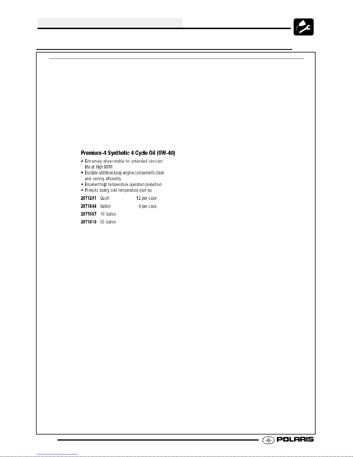
2871281 Engine Oil (Quart)Premium 4 Synthetic
0W-- 40 (4-- Cycle) (12 Count)
2871844 Engine Oil (Gallon) Premium 4 Synthetic
0W-- 40 (4-- Cycle) (4 Count)
2871567 Engine Oil (16 Gallon) Premium 4
Synthetic 0W--40 (4 --Cycle)
Gearcase / Transmission Lubricants
2873602 Premium Synthetic AGL Gearcase Lube
(12 oz. bottle)(12 Count)
2873603 Premium Synthetic AGL Gearcase Lube
(1 Gal.) (4 Count)
2876160 Premium ATV Angle Drive Fluid
(32 oz.) (12 Count)
2872276 Premium ATV Angle Drive Fluid
(2.5 Gal) (2 Count)
2870465 Oil Pump for 1 Gallon Jug
2871654 Premium Demand Drive Hub Fluid
(8 oz.) (12 Count)
Grease / Specialized Lubricants
2871322 Premium All Season Grease
(3 oz. cartridge)(24 Count)
2871423 Premium All Season Grease
(14 oz. cartridge)(10 Count)
2871460 Starter Drive Grease (12 Count)
2871515 Premium U-Joint Lube (3 oz.) (24 Count)
2871551 Premium U-Joint Lube (14 oz.) (10 Count)
2871312 GreaseGun Kit
2871329 Dielectric Grease (Nyogelt)
Coolant
2871323 60/40 Coolant (Gallon)(6 Count)
2871534 60/40 Coolant (Quart) (12 Count)
Part No. Description
Additives / Sealants / Thread Locking Agents /
Misc.
2874275 Loctitet Primer N, Aerosol
2871956 Loctitet Thread Sealant 565
(50 ml.)(6 Count)
2871949 Loctitet Threadlock 242
(50 ml.) (10 Count)
2871950 Loctitet Threadlock 242
(6 ml.)(12 Count)
2871951 Loctitet Threadlock 262
(50 ml.) (10 Count)
2871953 Loctitet Threadlock 271
(6 ml.)(12 Count)
2871954 Loctitet Threadlock 271
(36 ml.)(6 Count)
2870587 Loctitet 518 Gasket Eliminator/ Flange
Sealant (50 ml.) (10 Count)
2871326 Premium Carbon Clean
(12 oz.) (12 Count)
2870652 Fuel Stabilizer (16 oz.) (12 Count)
2871957 Black RTV Silicone Sealer
(3 oz. tube) (12 Count)
2871958 Black RTV Silicone Sealer
(11 oz. cartridge) (12 Count)
2870990 DOT3 Brake Fluid (12 Count)
2871557 Crankcase Sealant, 3-Bond 1215 (5oz.)
NOTE: The number count indicated by each part
number in the table above indicates the number of
units that are shipped with each order.
NOTE: Each item can be purchased separately at
your local Polaris dealer.
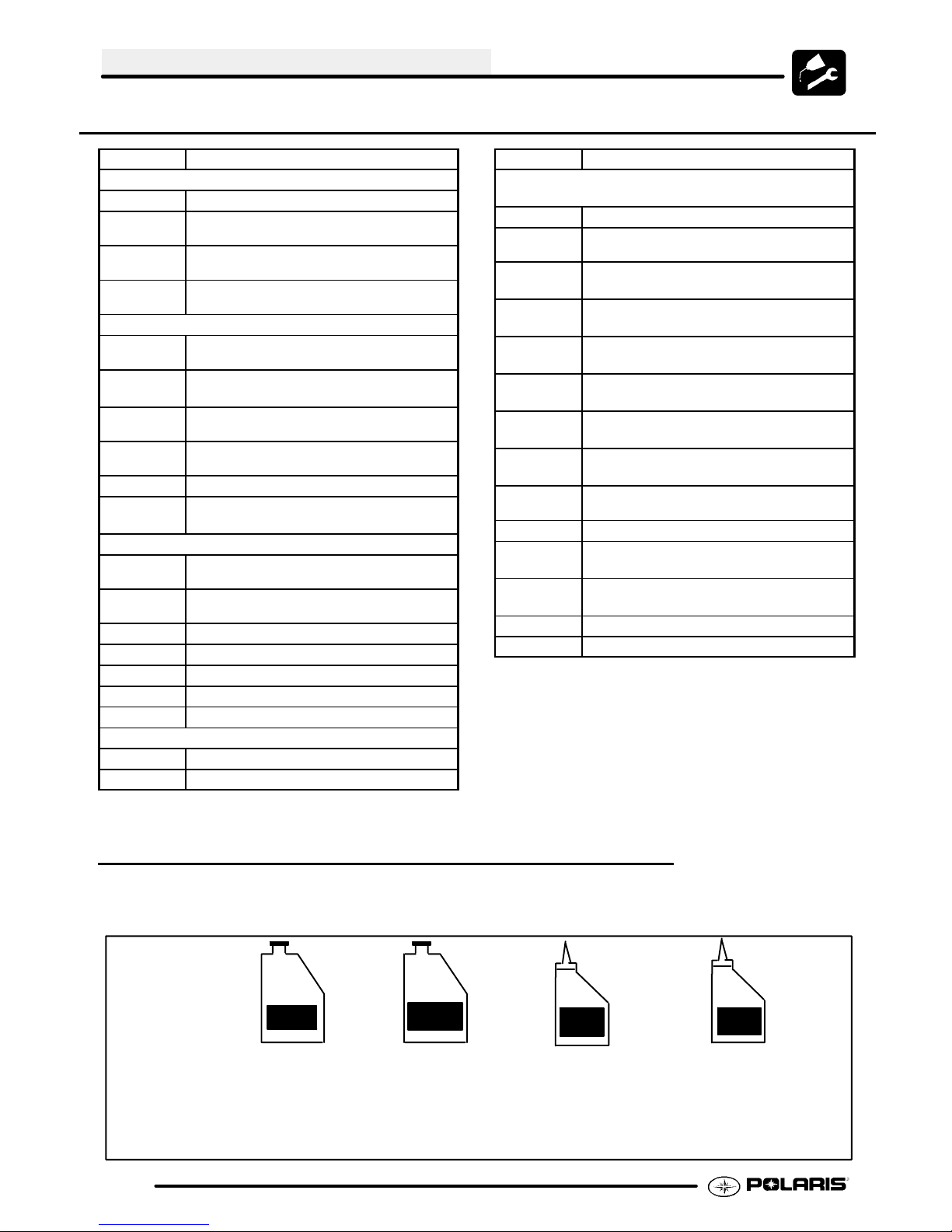
POLARIS LUBRICANT SYMBOL IDENTIFICATON
AGL
Polaris DOT 3
Brake Fluid
Polaris Sythetic
Gearcase Lube
AGL
U--Joint
Polaris U--Joint Lube
2.6
0W/40
Polaris Sythetic
OW-- 40 Oil
DHF
Polaris Demand
Drive Hub Fluid
Polaris All Season Grease
ADF
Polaris ATV
Angle Drive Fluid
Page 17
MAINTENANCE
PRE-RIDE / DAILY INSPECTION
Perform the following pre-ride inspection daily, and when servicing the vehicle at each scheduled maintenance.
G Tires - check condition and pressures
G Fuel and oil tanks - fill both tanks to their proper level; Do not overfill oil tank
G All brakes - check operation (includes auxiliary brake)
G Throttle - check for free operation
G Headlight/Taillight/Brakelight - check operation of all indicator lights and switches
G Engine stop switch - check for proper function
G Wheels - check for loose wheel nuts
G Air cleaner element - check for dirt or water; clean or replace
G Steering - check for free operation, noting any unusual looseness in any area
G Loose parts - visually inspect vehicle for any damaged or loose nuts, bolts or fasteners
G Engine coolant - check for proper level at the recovery bottle
COLD WEATHER KITS FOR 4 STROKE ATVS
Engine Heater -- (PN 2871507)
ACCESSORY ENGINE HEATER
2.7
Page 18
MAINTENANCE
POLARIS LUBES/FLUIDS FOR SCRAMBLER 500 MODELS
Pure Polaris Lubricants and Maintenance Kits can be purchased at your local Polaris dealer.
2873554 -- ATV Oil Change Kit
-- Oil Filter & 3 Qts. of 0W--40 oil
-- Reservoir Gasket
--DrainPlugGasket
-- Instruction Sheet
2.8
Page 19
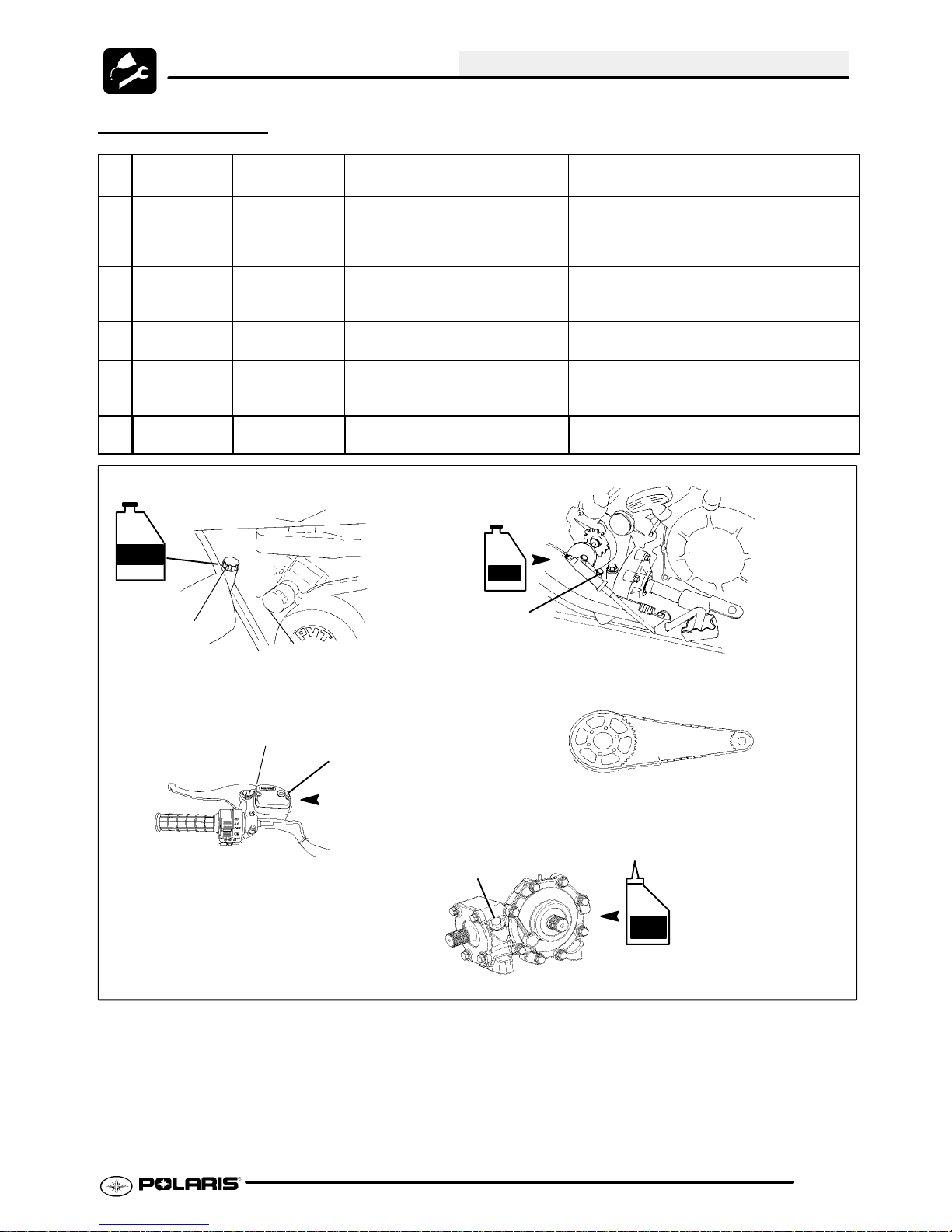
LUBRICATION
MAINTENANCE
Ill.
Item Lube Rec. Method Frequency*
#
1 Engine Oil Polaris 0W--40
Synthetic
2 Transmission Polaris AGL
Gearcase Lubricant
3 Brake Fluid Polaris DOT 3
Brake Fluid
4 DriveChain Polaris Chain
Lube or O-Ring
chain lube
5 FrontGear-
case
0W/40
ATV Angle
Drive Fluid
Dipstick
Filter
1. Engine Oil and Filter
Add oil to proper level. Change after 1st month, 6 months or 100
hours thereafter; Change more often (25-50
hours) in extremely dirty conditions, or short
trip cold weather operation.
Fill to bottom of fill hole. Approx. 32
oz.
Fill master cylinder reservoir to indicated level inside reservoir.
Apply to chain link plates and rollers.
Add to bottom of fill plug threads. Change annually©
AGL
Change annually ©
As required. Change fluid every 2 years.
As required*
Fill Plug
2. Transmission Fill Plug
Parking Brake Lock
3. Brake Fluid
Reservoir
4. Rear Drive Chain
Fill Plug
ADF
5. Front Gearcase
2.9
Page 20
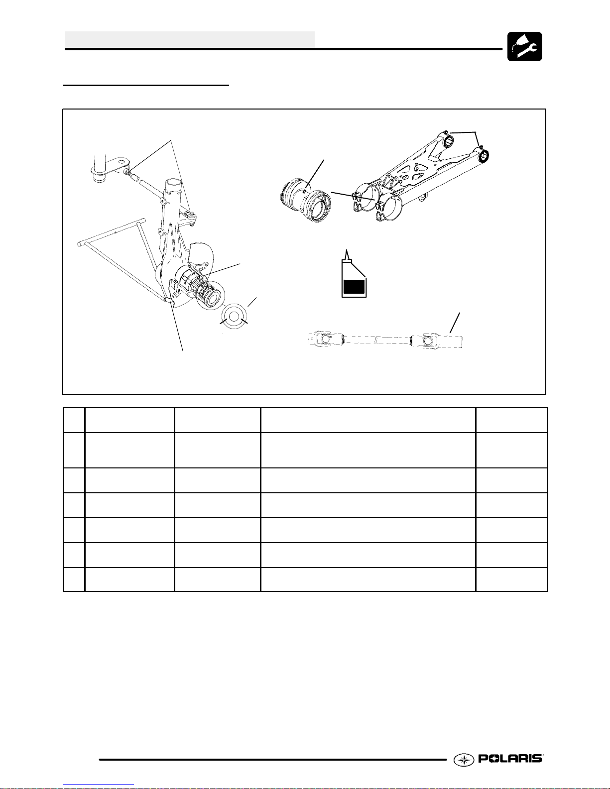
MAINTENANCE
LUBRICATION, CONT.
7. Tie Rod End
9. Swing Arm Bushings
10. Rear Concentric Housing
5. AWD Hubs
6. BallJoint
Ill.
#
5 AllWheel Drive
Hubs -- ATVs
6 Ball Joint Polaris All Season
7 Tie Rod Ends Polaris All Season
8 PropshaftYoke Premium U-Joint
9 Swing Arm Bush-
ings
10 Eccentric Housing Polaris All Season
Item Lube Rec. Method Frequency*
Polaris Demand
Drive Hub Fluid
Grease¢
Grease¢
Grease
Polaris All Season
Grease¢
Grease¢
4 or 8 O’clock position-
(end view)
Remove filler hole screw in hubs. Rotatewheels to
4 or 8 O’clock position. If lubricant is not visible add
until it flows from filler hole. Reinstall screw.
Locate grease fitting on back side of struts and
grease with grease gun.
Lift boot. Clean away dirt and grease. Apply fresh
grease by hand and reassemble.
Locate fittings and grease - 3 pumps maximum Annually©
Locate grease fitting on swing arm and grease with
grease gun.
Locate grease fitting on eccentric housing and
grease with grease gun.
DHF
8. Propshaft Yoke
(3 pumps max.)
Semi-annually
¡
Semi-annually
¡
Semi-annually
¡
Semi-annually
¡
Annually©
* More often under severe use, such as operated in water or under severe loads.
¡ Semi-annually or 50 hours of operation (refer to Maintenance Schedule for additional information)
More often under severe conditions (operating in water or hauling heavy loads)
© Annually or 100 hours of operation (refer to Maintenance Schedule for additional information)
More often under severe conditions (operating in water or hauling heavy loads)
¢ Grease conforming to NLGI No. 2, such as Polaris Premium All Season Grease, Conoco Superlube M or
Mobilegrease Special
2.10
Page 21
MAINTENANCE
LUBRICATION / GREASE
POINTS
As shown on Page 2.7, there are only five grease
zerks on the Trail Blazer, two front ball joints, two on
theswingarepivots, andoneontherearaxlehousing.
Swing Arm Pivot
Each Side
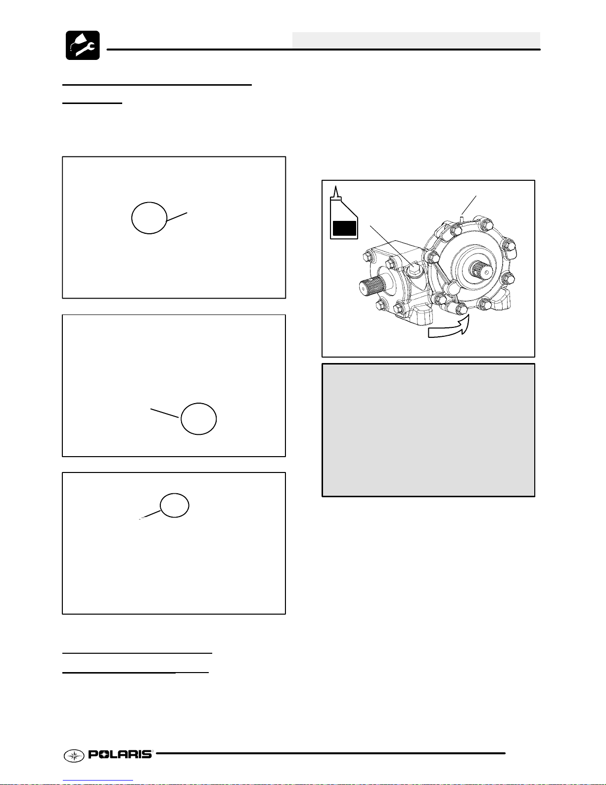
G Be sure vehicle is level before
proceeding.
G Check vent hose to be sure it is
routed properly and unobstructed.
G The correct gearcase lubricant to
use is ATV Angle Drive Fluid (PN
2871653), or an equivalent lubricant
with a GL5 rating.
Make sure vent is unobstructed
Fill plug
ADF
Drain plug
Ball Joint Zerk
Each Side
Ball Joint Zerk
FRONT GEARCASE
LUBRICATION
The gearcase lubricant level should be checked and
changed in accordance with the maintenance
schedule.
(4X4)
FRONT GEARCASE SPECIFICATIONS
Specified Lubricant:
ATV Angle Drive Fluid (PN 2871653)
Capacity: 4.0 Oz. (120ml.)
Drain Plug / Fill Plug T orque:
14 ft. lbs. (19.4 Nm)
To check the level:
1. Remove the fill plug. Inspect the level of lube.
AddATVAngleDriveFluid(PN 2871653) until
level of fluid is flush with the bottom of the fill plug
threads.
To change lubricant:
1. Remove gearcase drain plug located on the
bottom and drain oil. Catch and discard used oil
properly.
2. Cleanand reinstall drainplug using a newsealing
washer.
3. Remove fill plug.
4. Add proper amount of lubricant.
5. Install fill plug.
6. Check for leaks.
2.11
Page 22
MAINTENANCE
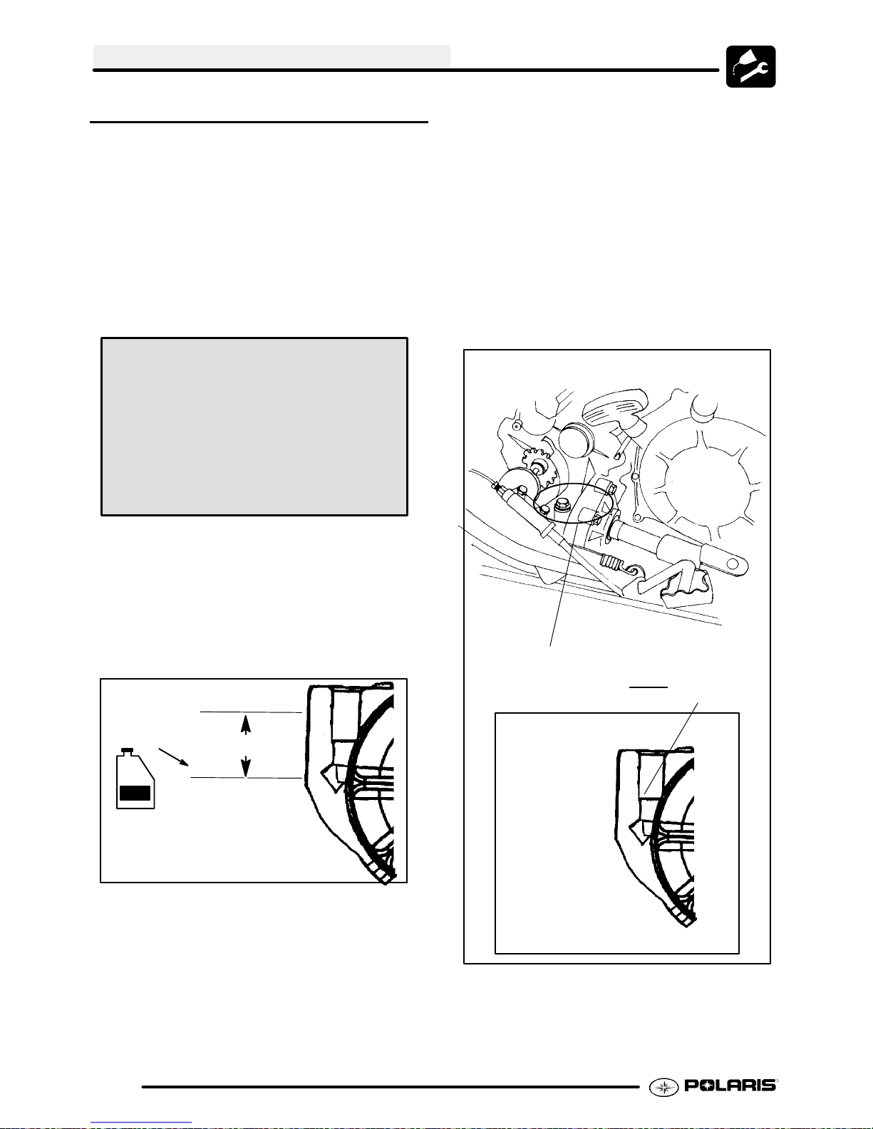
TRANSMISSION LUBRICATION
The transmission lubricant level should be checked
and changed in accordance with the maintenance
schedule.
G Be sure vehicle is level before
proceeding.
G Check vent hose to be sure it is
routed properly and unobstructed.
G Follow instructions on following
pages to check / change
transmission lubricant.
TRANSMISSION SPECIFICATIONS
Specified Lubricant:
Polaris AGL Gearcase Lubricant (PN 2873603)
(Gallon) (PN 2873602) (12 oz.)
Capacity: 4x4 -- 32 oz. / 945 ml
Drain Plug / Fill Plug T orque:
14 ft. lbs. (19.4 Nm)
To change lubricant:
1. Removepropshaft shieldfromthe rightsideof the
vehicle.
2. Remove transmission drain plug drain the oil.
Catch and discard used oil properly.
3. Clean and reinstall the drain plug with a new
sealing washer. Torque to specification.
4. Remove fill plug.
5. Add Polaris AGL Gearcase Lubricant (PN
2873602) to proper level as described above.
6. Check for leaks.
7. Reinstall propshaft shield.
Right Side View of A TV
4x4 Models
To check the level:
1. Removepropshaft shieldfromthe rightsideof the
vehicle.
2. Remove fill plug and visually inspect the oil level.
Level is correct when it reaches the bottom of the
fill hole as shown below.
Oil Level
AGL
15/8″
View From Front
Transmission Fill Plug
Do not fill to bottom
of fillplug threads
2.12
Page 23
MAINTENANCE
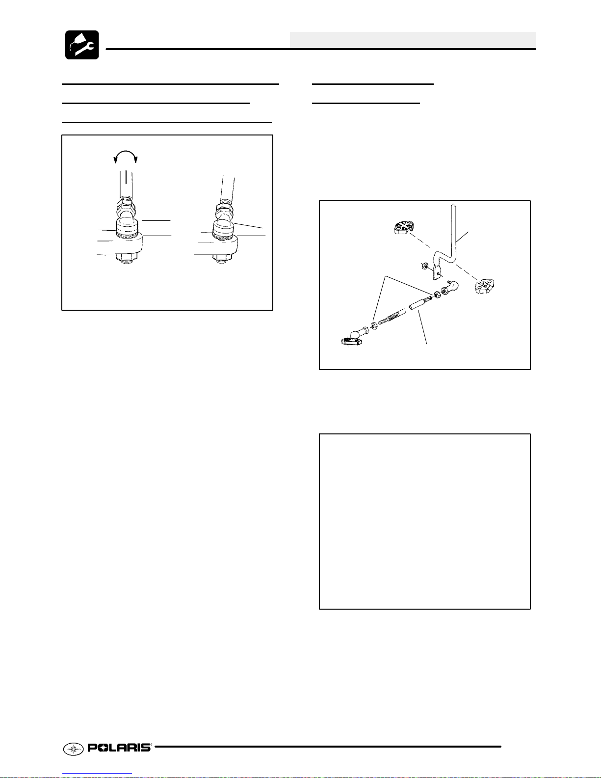
TRANSMISSION GEARSHIFT
LINKAGE
PRELIMINARY
Correctly Tightened
Jam Nut
G Ifshiftingproblems areencountered,
thetransmission linkagemayrequire
adjustment.
G Visually check for contact of shift
lever to shifter opening in the front
fender. Ensure shift linkage or shift
lever is not contacting the frame or
exhaust components.
G Tightenshiftlinkage rodendjam nuts
properly after adjustment. You
should be able to rotate the linkage
rod between 1/8 and 1/4 turn after
both jam nuts are tight.
G The transmission shift linkage
should be periodically inspected for
wear and parts replaced as required
to remove excess play from shift
linkage.
G Refer to Transmission chapter for
more information.
NOTE: Therod end must be held whentighteningthe
jam nut to prevent damage to the rod end.
ADJUSTMENT,
INSPECTION
Linkage rod will rotate
1/8 -1/4 turn if rod ends
are tightened properly.
Parallel
Incorrectly Tightened
Jam Nut
SHIFT LINKAGE
ADJUSTMENT
1. Inspect shift linkage tie rod ends, clevis and pivot
bushings and replace if worn or damaged.
2. Place gear selector in neutral.
3. Loosen rod end adjuster jam nuts (A) on both
ends of linkage rod. NOTE: The jam nut with
yellow plating is Left Hand thread.
Gear Selector
Arm
Jam Nuts (A)
Linkage Rod
Ill. 1
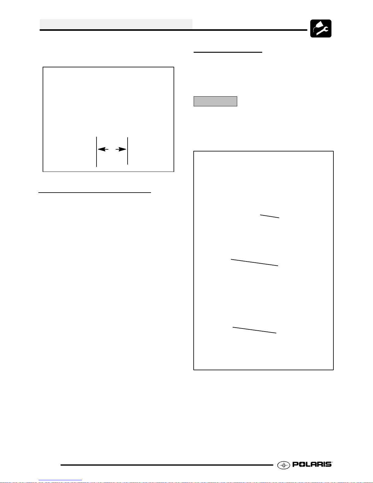
4. Turn linkage rod (A) to shorten or lengthen rod
until the shift lever is centered on hole in the fender.
A
2.13
Page 24
MAINTENANCE
5. Hold rod end parallel to mounting surface and
tighten jam nuts securely.
Center Lever
In Slot
THROTTLE OPERATION
Check for smooth throttle opening and closing in all
handlebar positions. Throttle lever operation should
be smooth and lever must return freely without
binding.
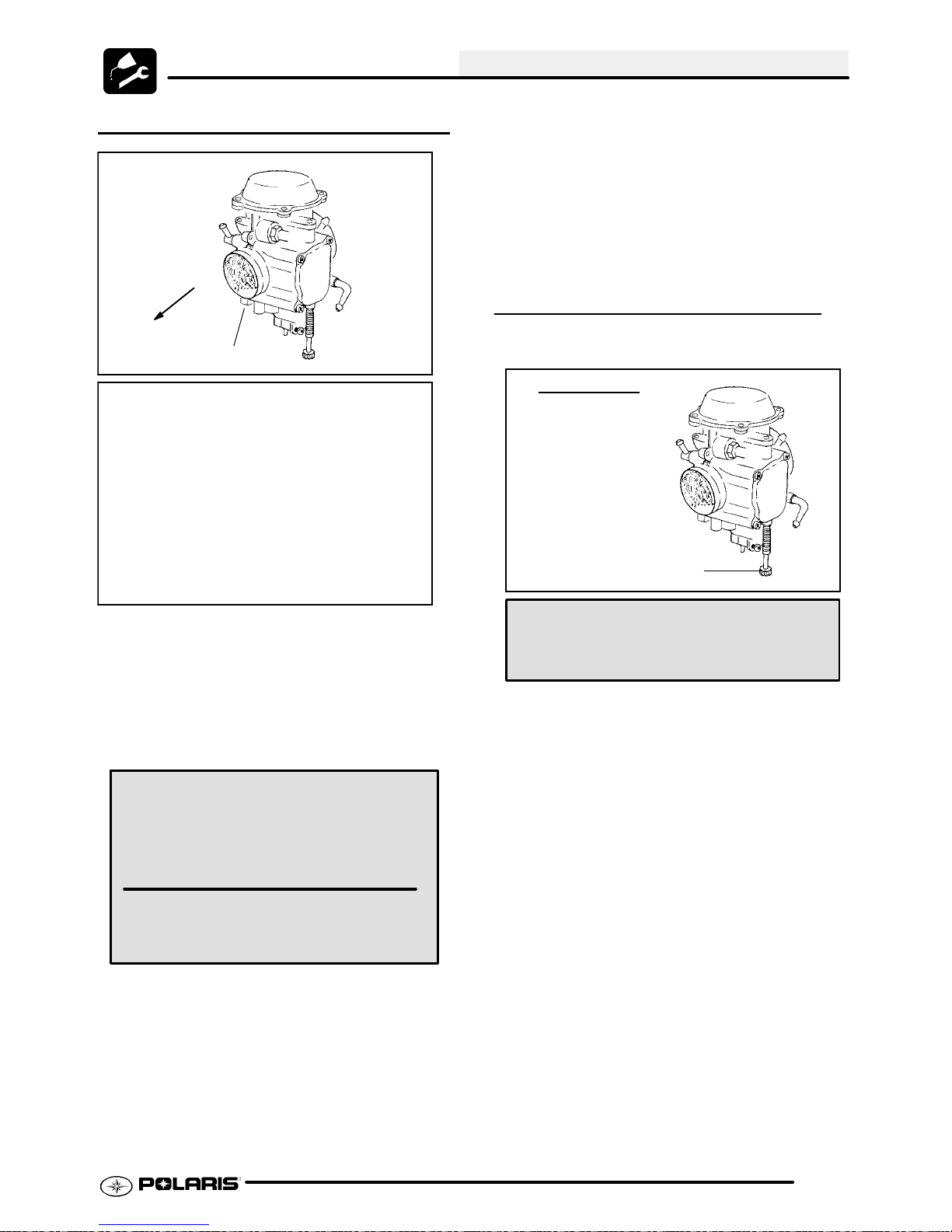
PILOT SCREW
Thepilotsystem suppliesfuelduringengine operation
with the throttle valve closed or slightly opened. The
fuel/air mixture is metered by pilot screw and
discharged into the main bore through the pilot outlet.
CAUTION:
The pilotscrew is calibratedatthe factoryto meetEPA/ CARB
regulationsfor air qualitystandards and is sealed with a brass
plug to prevent tampering. Removal of the tamper proof plug
is not permitted. For service purposes, cleaning of the pilot
circuitcan be done only by a certifiedrepairshop to ensure air
quality standards are not exceeded.
Pilot Screw location
1. Place the gear selector in neutral.
2. Set parking brake.
3. Start the engine and let it idle.
4. Turn handlebars from full right to full left. If idle
speed increases at any point inthe turningrange,
inspect throttle cable routing and condition. If
cable is routed properly and in good condition,
repeat adjustment procedure.
5. Replace the throttle cable if worn, kinked, or
damaged.
Brass Plug Installed
Brass Plug Removed
2.14
Page 25
MAINTENANCE
PILOT SCREW ADJUSTMENT
FRONT
(Engine)
Pilot Screw
View -- Right Cover Panel Removed
6. Slowly turn mixture screw counterclockwise until
idle speed increases to maximum RPM.
Continue turning counterclockwise until idle RPM
begins to drop.
7. Center the pilot screw between thepoints in Step
5 and 6.
8. Re adjust idle speed if not within specification.
IDLE SPEED ADJUSTMENT
1. Start engine and warm it up thoroughly.
CV Carburetor
Pilot Screw
1. Start engine and warm it up to operating
temperature (about 10 minutes).
2. Turnpilot screw in (clockwise) until lightly seated.
Turn screw out the specified number of turns.
NOTE: Do not tighten the pilot screw forcefully
against the seat or the screw and/or seat will be
permanently damaged.
The pilot screw is set at the factory.
Each carburetor will have a slightly different pilot screw setting, the adjustments
below are the recommended settings, the
settings may differ from these recommendations.
Pilot Screw Adjustment:
Scrambler 500 -- 2 Turns Out
3. Connect an accurate tachometer that will read in
increments of + or -- 50 RPM such as the PET
2100DX (PN 8712100DX) or the PET 2500 (PN
8712500).
4. Set idle speed to 1200 RPM. Always check
throttle cable freeplay after adjusting idle speed
and adjust if necessary.
5. Slowly turn mixture screw clockwise using the
pilot screw wrench until engine begins to miss.
Idle Screw
Idle Speed:
1200 +/-- 200 RPM
2. Adjust idle speed by turning the idle adjustment
screw in (clockwise) to increase or out
(counterclockwise) to decrease RPM. (Refer to
Ill. at right).
NOTE: Adjusting theidle speed affects throttle cable
freeplay and electronic throttle control (ETC)
adjustment. Always check throttle cable freeplay
after adjusting idle speed and adjust if necessary.
2.15
Page 26
MAINTENANCE
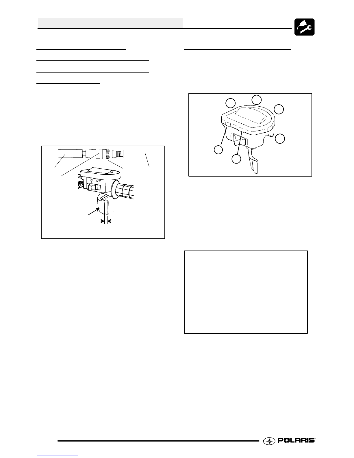
THROTTLE CABLE /
ELECTRONIC
CONTROL (ETC
THROTTLE
SWITCH)
ADJUSTMENT
1. Slide the boots off inline cable adjuster sleeve.
Loosen adjuster locknut.
2. With handlebars centered and wheels pointing
forward, turn adjuster sleeve until 1/16″ -1/8″
freeplay is achieved at the thumb lever. After
making any adjustment, “flip” the lever slightly to
confirm adjustment.
Boot
Adjuster
Sleeve
Direction
of travel
3. Tighten locknut and slide boots over cable
adjuster until they touch at the middle point of the
adjuster.
4. Withengine running, turn the handlebars fromfull
left to full right with transmission in neutral.
Engine RPM should not change and the engine
should not die. If either of these occur, return to
the first step.
1/16″ -1/8″
Freeplay
Lock-
nut
Boot
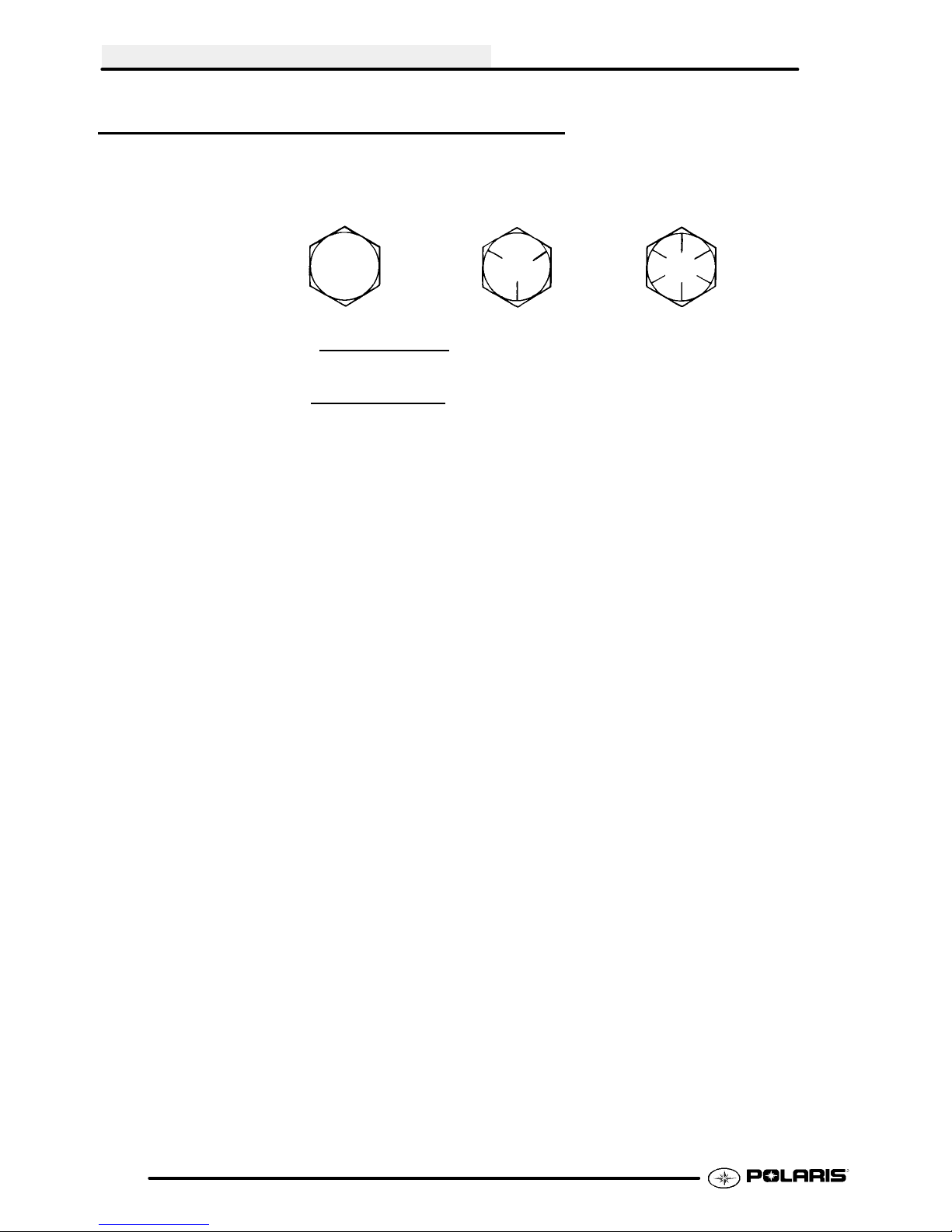
THROTTLE OPERATION
To remove the ETC cover:
1. Use a medium flat blade screwdriver and insert
blade into the pockets of the cover starting on the
#1 position.
3
6
5
2. Twistscrewdriver slightly while lifting onthecover
to release snap.
3. Repeat procedure at the other five locations as
shown. NOTE: Do not attempt to remove cover
until all latch points are released.
Check for smooth throttle opening and closing in all
handlebar positions. Throttle lever operation should
be smooth and lever must return freely without
binding. Replace the throttle cable if worn, kinked, or
damaged.
2
1
4
2.16
NOTE: When replacing the cover, check for correct
placement of cover O-ring.
Page 27
MAINTENANCE
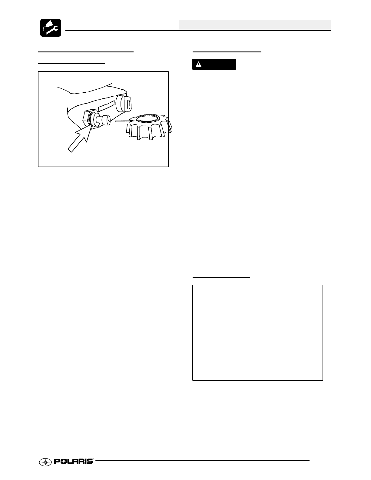
CHOKE (ENRICHER)
ADJUSTMENT
Boot
If the choke knob does not stay out when pulled,
adjust the choke tension by tightening the tensioner
located under the rubber boot between the choke
knob and nut. Firmly grasp the rubber boot and
tighten until thechoke slides freely but stays out when
pulled.
Verify free play of 1/16--3/16” (1.6--4.76 mm) and
smooth operation of choke cable.
If smooth choke operation is not obtainable, inspect
choke cable for kinks or sharp bends in routing.
FUEL SYSTEM
WARNING
Gasoline is extremely flammable and explosive
under certain conditions.
G Always stop the engine and refuel
outdoors or in a well ventilated area.
G Do not smoke or allow open flames
or sparks in or near the area where
refueling is performed or where
gasoline is stored.
G Donot overfill the tank. Donot fill the
tank neck.
G If you get gasoline in your eyes or if
you swallow gasoline, seek medical
attention immediately.
G If you spill gasoline on your skin or
clothing, immediately wash it off with
soapand water and change clothing.
G Never start the engine or let it run in
an enclosed area. Engine exhaust
fumes are poisonous and can result
loss of consciousness or death in a
short time.
G Never drain the float bowl when the
engine is hot. Severe burns may
result.
FUEL LINES
Fuel Lines
Pulse Line
Fuel Pump
Ill.1
1. Check fuel lines for signs of wear, deterioration,
damage or leakage. Replace if necessary.
2. Besurefuel linesare routed properly andsecured
with cable ties. CAUTION: Make sure lines are
not kinked or pinched.
3. Replace all fuel lines every two years.
Fuel Filter
2.17
Page 28
MAINTENANCE
VENT LINES
1. Check fuel tank, oil tank, carburetor, battery and
transmission vent lines for signs of wear,
deterioration, damage or leakage. Replace every
two years.
2. Be sure vent lines are routed properly and
secured with cable ties. CAUTION: Make sure
lines are not kinked or pinched.
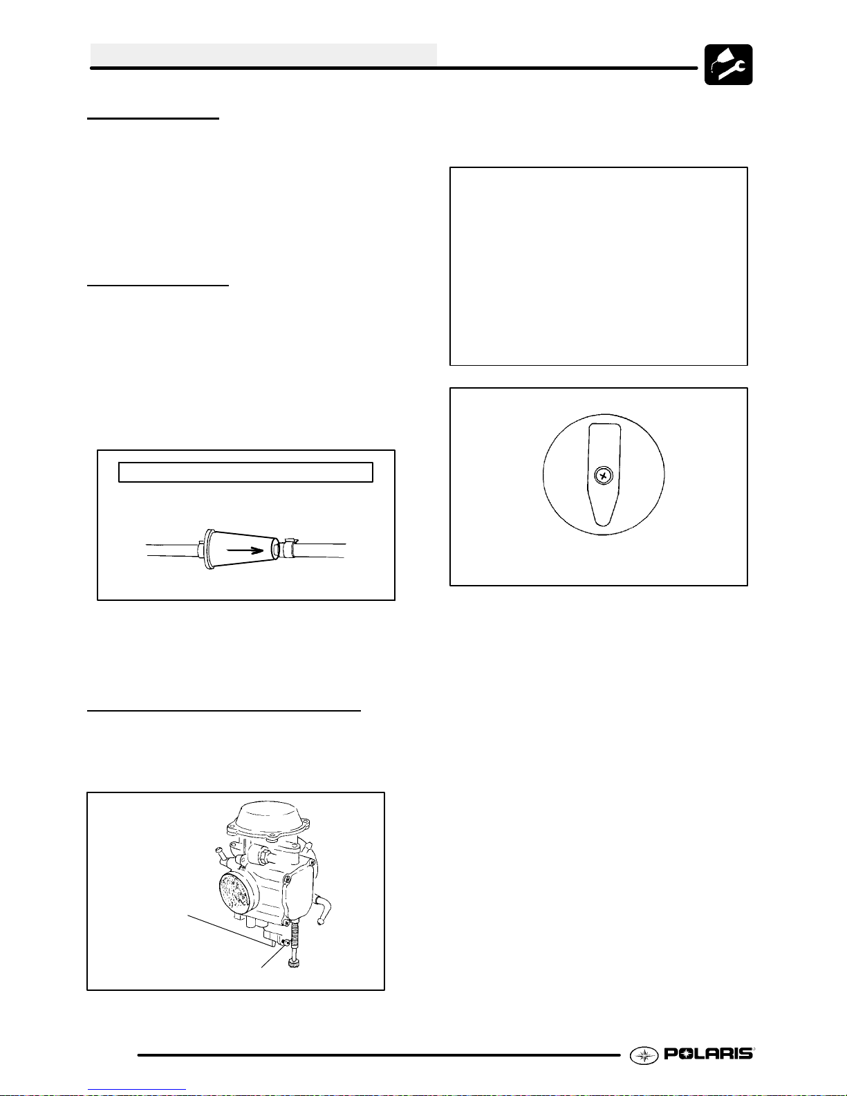
FUEL FILTER
The fuel filter should be replaced in accordance with
the Periodic Maintenance Chart.
1. Shut off fuel supply at fuel valve.
2. Remove line clamps at both ends of the filter.
3. Remove fuel lines from filter.
4. Install new filter and clamps onto fuel lines with
arrow pointed in direction of fuel flow.
Fuel Filter Located Close To Carburetor
1. Turn fuel valve to the off position.
2. Place a clean container beneath the bowl drain
spigot or bowl drain hose.
Fuel Valve Location
RES
OFF
Arrow Indicates Direction of Flow
To Carburetor
5. Install clamps on fuel line.
6. Turn fuel valve ON.
7. Start engine and inspect for leaks.
CARBURETOR DRAINING
The carburetor float bowl should be drained
periodically to remove moisture or sediment from the
bowl, or before extended periods of storage.
Drain tube
attached
here
ON
Fuel Valve
3. Turn drain screw out two turns and allow fuel in
the float bowl and fuel line to drain completely.
4. Inspect the drained fuel for water or sediment.
5. Tighten drain screw.
6. Turnfuelvalveto“ON”.
7. Start machine and check for leaks.
NOTE: If there is a tube attached, it must be
reattached as this will effect engine performance.
Drain Screw
NOTE: Thebowl drain screwis located onthebottom
left side of the float bowl.
2.18
Page 29
MAINTENANCE
COMPRESSION TEST
NOTE: This Polaris 4-Strokeengine is equipped with
an automatic decompressor. Compression readings
will vary in proportion to cranking speed during the
test. Average compression (measured) is about
70--90 psi
Smooth idle generally indicates good compression.
Low engine compression is rarely a factor in running
condition problems above idle speed. Abnormally
high compression can be caused by a decompressor
malfunction, or worn or damaged exhaust cam lobes.
Inspect camshaft and automatic decompression
mechanism if compression is abnormally high.
A cylinder leakage test isthe best indication ofengine
condition on models with automatic decompression.
Follow tester manufacturer’s instructions to perform
a cylinder leakage test. (Never use high pressure
leakage tester as crankshaft seals may dislodge and
leak).
Cylinder Compression w/ decompressor
Cylinder Leakage
during a compression test.
Standard 70--90 PSI
BATTERY MAINTENANCE
WARNING
Battery electrolyte ispoisonous. Itcontains
sulfuric acid. Serious burnscanresultfrom
contact with skin, eyes or clothing. Antidote:
External: Flush with water.
Internal: Drink large quantities of water or
milk. Follow with milk of magnesia, beaten
egg, or vegetable oil. Call physician immediately.
Eyes: Flush with water for 15 minutes and
get prompt medical attention.
Batteries produce explosive gases. Keep
sparks, flame, cigarettes, etc. away. Ventilate when charging or using in an enclosed
space. Always shield eyes when working
nearbatteries. KEEPOUTOF REACH OF
CHILDREN.
Service Limit: 10 %
(Inspect for cause if leakage exceeds 10%)
ENGINE MOUNTS
Inspect rubber engine mounts for cracks or damage.
ENGINE FASTENER TORQUE
Check engine fasteners and ensure they are tight.
SEALED LOW MAINTENANCE
BATTER
NOTE: All Low Maintenance batteries are fully
charged and tested at the factory before
installation. Expected shelf life varies on storage
conditions. As a general rule before placing the
battery into service, check the battery condition
and charge accordingly .
Battery Check:
1. Check the date label on the side of the battery to
calculate when to check voltage. The battery
should be checked every 3 months.
2. Check the voltagewith a voltmeter or multimeter.
A fully charged battery should be 12.8 V
higher
3. Ifthe voltage is below12.8V,the battery will need
to be recharged.
Y
or
.
2.19
Page 30
MAINTENANCE
SEALED LOW MAINTENANCE
New Batteries: Batteries must be fully charged
before use or battery life can be reduced by
10-30% of full potential. Charge battery for 3--5
hours using a variable rate charger. Do not use
thealternator tochargeanew battery. A high rate
battery charger can cause battery damage.
Low Maintenance batteries are permanently
sealed at the time of manufacture. The use of
lead--calcium and AGM technology instead of
lead--antimony allows the battery acid to be fully
absorbed. For this reason, a Low Maintenance
battery case is dark and the cell caps are not
removable, since there is no need to check
electrolyte level.
NEVER
Maintena nc e batte r y. Doing so will damage the
case and shorten the life of the battery. Refer to the
Battery Activation and Maintenance Video (PN
9917987) for proper instruction on servicing Low
Maintenance batteries.
NEVERattempt to add electrolyteor waterto a Low
Maintena nc e batte r y. Doing so will damage the
case and shorten the life of the battery. Refer to the
Battery Maintenance Video (PN 9917987) for proper
instruction on servicing Low Maintenance
batteries.
attempt to add electrolyte or water to a Low
BATTERY
If battery voltage is 12.8 V or less, the battery may
need recharging. When using an automatic charger,
refer to the charger manufacturer’s instructions for
recharging. When using a constant current charger,
use the following guidelines for recharging.
NOTE: Always verify battery condition beforeand 1-2
hours after the end of charging.
WARNING: An overheated battery could explode,
causing severe injury or death. Always watch
charging times carefully. Stop charging if the battery
becomes very warm to the touch. Allow it to cool
before resuming charging.
CHARGING
Battery Charging Reference Table
State of
Charge
100% 12.8--13 V None,
75--100% 12.5--12.8 V May need
50--75% 12.0--12.5 V Needs
25--50% 11.5--12.0 V Needs
0--25% 11.5 V or
Voltage Action Charge
Time
note below)
None Re-
less
check voltage at 3
mos. after
manufacture date
slight
charge
Charge
Charge
Needs
Charge
quired
3--6 hours
5--11 hours
At least 13
hours,
verify state
of charge
At least 20
hours
(*See
To service a Low Maintenance battery:
1. Remove battery from the vehicle
2. Test battery with a voltage meter or load tester to
determine battery condition. This will determine
thelengthof time requiredto chargethebatteryto
full capacity. Refer to capacity table.
3. Charge battery using a variable rate charger.
2.20
Page 31

MAINTENANCE
SEALED LOW MAINTENANCE
BATTERY
REMOV
The battery is located under the seat and right rear
fender.
NOTE: New Batteries: Batteries must be fully
charged before use or batterylifewill be reduced
by 10-30%of full potential. Charge battery for3--5
hours at a current equivalent of 1/10 of the
battery’sratedamp/hourcapacity. Do not usethe
alternatorto chargea new battery.(Referto battery
video PN 9917987)
INSPECTION/
AL
Battery Location
SPARK PLUG
1. Removespark plug hightension lead. Cleanplug
area so no dirt and debris can fall into engine
when plug is removed.
2. Remove spark plug.
3. Inspect electrodes for wear and carbon buildup.
Look for a sharp outer edge with no rounding or
erosion of the electrodes.
4. Clean with electrical contact cleaner or a glass
bead spark plugcleaner only. CAUTION: A wire
brush or coated abrasive should not be used.
5. Measure gap with a wire gauge. Refer to
specifications for proper spark plug type andgap.
Adjust gap if necessary by bending the side
electrode carefully.
To remove the battery:
1. Disconnect holder strap and remove cover.
2. Disconnect battery negative (-)(black) cablefirst,
followed by the positive (+) (red) cable.
CAUTION
To reduce the chance of sparks: Whenever
removing the battery, disconnect the negative
(black) cable first. When reinstalling the battery,
install the negative cable last.
3. Remove the battery and recharge according to
the charge chart.
4. Clean battery cables and terminals with a stiff wire
brush. Corrosion can be removed using a solution
of one cup water and one tablespoon baking soda.
Rinse well with clean water and dry thoroughly.
5. Reinstallbattery,attaching positive(+)(red) cable
first and then the negative (-) (black) cable.
6. Coat terminals and bolt threads with Dielectric
Grease (PN 2871329).
7. Reinstall battery cover and holder strap.
Spark Plug Gap
.036″ (.9 mm)
6. If necessary,replacespark plug with proper type.
CAUTION: Severe engine damage may occur if
the incorrect spark plug is used.
7. Apply a small amount of anti-seize compound to
the spark plug threads.
8. Installsparkplug andtorqueto 14 ft. lbs. (19Nm).
Recommended Spark Plug:
NGK BKR6E
Spark Plug Torque: 14 Ft. Lbs.
(12--15 Nm)
2.21
Page 32
MAINTENANCE
IGNITION TIMING
Refer to Electrical chapter for ignition timing
procedure.
Ignition Timing:
30°±2° BTDC@5000RPM
ENGINE-TO -FRAME GROUND
Inspect engine-to-frame groundcableconnection. Be
sure it is clean and tight.
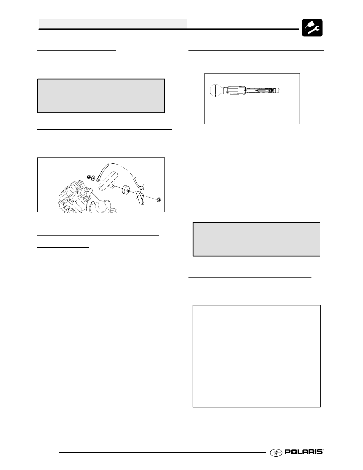
COOLANT STRENGTH / TYPE
Test the strength of the coolant using an antifreeze
hydrometer.
Antifreeze Hydrometer
G A 50/50 or 60/40 mixture of Polaris
Premium Coolant (PN 2871323) and
distilled water will provide the
optimum cooling, corrosion
protection, andantifreezeprotection.
G Do not use tap water. Tap water
contains minerals and impurities
which build up in the system. Do not
add straight antifreeze or straight
water to the system. Straight water
or antifreeze may cause the system
to freeze, corrode, or overheat.
LIQUID COOLING SYSTEM
OVER
Theengine coolant level iscontr olled ormaint ained
by the recovery system. The recovery system
components are t he recovery bottle, radiator filler
neck, radiator pressure cap and connecting hose.
As coolant operating temperature increases, the
expanding(heated)excesscoolant isforcedout ofthe
radiatorpast the pressure capand int o the recovery
bottle. Asenginecoolanttemperat ur edecreasesthe
contracting ( c ooled)coolant isdrawn bac kupf r omthe
tank past t he pressure cap and int o the radiator.
VIEW
G Some coolant level drop on new
machinesisnormalasthesystemis
purging it s elfoftrapped air.Obser ve
coolant levels often during t he
break-in period.
G Overheating of engine could occur if
air is not fully purged from system.
G PolarisPremium60/40anti --freezeis
premixed and ready to use. Do not
dilute wit h water.
Polaris 60/40 Anti-Freeze / Coolant
(PN 2871323)
COOLING SYSTEM HOSES
1. Inspect all hoses for cracks, deterioration,
abrasion or leaks. Replace if necessary.
2.22
2. Check tightness of all hose clamps.
CAUTION: Do not over-tighten hose clamps at
radiator, or radiator fitting may distort, causing a
restriction to coolant flow. Radiator hose clamp
torque is 36 in. lbs. (4 Nm).
Page 33

MAINTENANCE
RADIATOR
1. Check radiator air passages for restrictions or
damage.
2. Carefully straighten any bent radiator fins.
3. Remove any obstructions with compressed air or
low pressure water.
COOLING SYSTEM
PRESSURE
Refer to Page 3.6 for pressure test procedure.
TEST
COOLANT LEVEL
INSPECTION
WARNING
Never remove the radiator pressure cap when the
engineiswarmorhot. Escapingsteamandfluidcan
causesevere burns. Theengine mustbe allowedto
cool before removing the pressure cap.
2. Fill reservoir to upper mark with Polaris Premium
60/40 Anti Freeze / Coolant (PN 2871323)ora
mixture of antifreeze and distilled water as
required for freeze protection in your area.
3. Reinstall cap.
NOTE: Ifoverheating is evident, allow system to cool
completely and check coolant level in the radiator.
Inspect for signs of trapped air in system.
RADIATOR COOLANT LEVEL
INSPECTION
NOTE: This procedure is only required if the cooling
system has been drained for maintenance and/or
repair. However ,if the recovery bottle has run dry, or
if overheating is evident, the level in the radiator
should be inspected and coolant added if necessary.
WARNING
Never remove the radiator pressure cap when the
engineiswarmorhot. Escapingsteamandfluidcan
causesevere burns. Theengine mustbe allowedto
cool before removing the pressure cap.
Ther ecov erybott le(A),locat edontheleftsideofthe
machine,mustbemaint ainedbetweentheminimum
and maxim um levels.
A
With the engine at operating temperature, the coolant
level should be between the upper andlower marks
on the coolant reservoir. If it is not:
1. Remove reservoir cap. Verify the inner splash
cap vent hole is clear and open.
NOTE: Use of a non-standard pressure cap will not
allow the recovery system to function properly.
To access the radiator pressure cap:
Remove front cover by placing your fingers under the
front of the cover and pull upward.
Pressure Cap
2.23
Page 34

MAINTENANCE
MAIN AIR FILTER CLEANING
It is advisable to replace the filter when it is dirty.
However, in an emergency it is permissible to clean
the main filter if you observe the following practices.
G Never immerse the filter in water
since dirt can be transferred to the
clean air side of the filter.
G If compressed air is used never
exceedapressureof 40PSI. Always
use a dispersion type nozzle to
prevent filter damageand clean from
the inside to the outside.
G Replace the air filter every 50 hours,
and possibly more often in very dirty
conditions.
AIR FILTER/PRE-FILTER
SER
It is recommended that the air filter and pre filter be
replaced annually. When riding in extremely dusty
conditions, replacement is required more often.
Theprefiltershould becleanedbeforeeachrideusing
the following procedure:
1. Lift up on the rear of the seat.
2. Pull the seat back and free of the tabs. NOTE:
3. Remove clips (A) from air box cover and remove
VICE
When reinstalling seat, make sure the slots in the
seat engage the tabs in the fuel tank.
cover. Inspect the gasket. Itshould adheretightly
to the cover and seal all the way around.
4. Loosen clamp and remove air filter
assembly.
Cover
Pre-filter
Main Element
Ill.1
Cleaning:
5. Slip the pre-filter element off of main element.
Clean the pre filter with high flash point solvent,
followed by hot soapy water.
6. Rinse and dry thoroughly.
7. Inspect element for tears or damage.
8. Apply foam filter oil or clean engine oil and
squeeze until excess oil is removed.
9. Inspect main filter and replace if necessary . If the
filter has been soaked with fuel or oil it must be
replaced.
Installation:
10. Reinstall pre-filter element over main filter. Be
sure the element covers entire surface of main
filter without folds, creases, or gaps.
1 1. Reinstall filter on main filter mount. Place filter
clamp over the assembly and tighten.
Carb Boot
Gasket
2.24
NOTE: Apply a small amount of general purpose
grease to the sealing edges of the filter before
reinstalling.
A
Page 35

Filter Clamp
Ill.2
Proper Filter Placement
Filter Support
Main Filter
MAINTENANCE
Sediment Tube
NOTE: Thesediment tube willrequire morefrequent
service if the vehicle is operated in wet conditions or
at high throttle openings for extended periods.
1. Remove drain plug from end of sediment tube.
2. Drain tube.
3. Reinstall drain plug.
Air Box
Ill.3
NOTE: The air filter should rest on the filter support.
Proper placement of the air filter is important to
prevent rattles and air leaks. See Illustration above.
12. Install air box cover and secure with clips.
Front
AIR BOX SEDIMENT TUBE
Periodically check the air box drain tube located
toward the rear of the machine. Drain whenever
deposits are visible in the clear tube.
BREATHER FILTER
INSPECTION
Polaris Four cycle ATV engines are equipped with a
breather filter. The in-line filter is similar in
appearanceto afuelfilter,andis visibleon the leftside
(Location A).
Typical Breather Filter Location
In-Line Breather Filter
Location A
1. In-line breather filters should be installed with the
arrow pointing toward the engine (away from the
air box).
2.25
Page 36
MAINTENANCE
BREATHER HOSE
1. Be sure breather line is routed properly and
securedinplace. CAUTION: Makesurelinesare
not kinked, pinched or has any sags that may
collect and hold moisture.
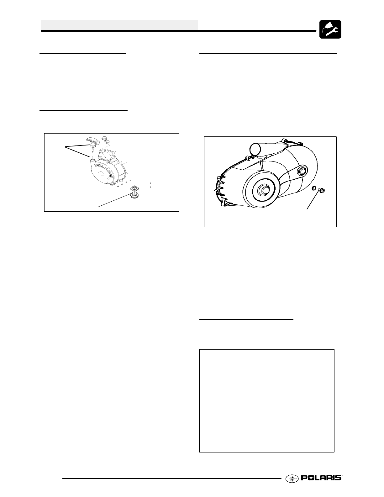
RECOIL HOUSING
G Drain the housing periodically to
remove moisture.
B
Recoil Drain
G Drain the recoil housing after
operating the ATV in very wet
conditions. Thisshould also be done
before storing the ATV. The drain
screw is located at the bottom of the
recoil housing. Remove the screw
with a 10 mm wrench. Reinstall
screw once housing has been
drained.
G CAUTION: Make sure the manual
start handle is fully seated on the
recoil housing, especially when
travelling in wet areas. If it is not
sealed properly, water may enter the
recoil housing and damage
components.
G Water will enter the recoil housing if
the starter handle is disengaged
from the rope guide when under
water.
G After travelling in wet areas, the
recoil housing and starter should
always be drained completely by
removing the recoil.
G Do not open the crankcase drain
unless the engine has ingested
water. Some engine oil will be lost if
crankcase drain is opened.
G If recoil handle seal has been
damaged, the handle assembly
should be replaced.
PVT DRAIN PLUG & DRYING
NOTE: If operating the ATV in or through water, be
sure to check the PVT cover and other components
for water ingestion. The A TV should be checked
immediately.
1. To release any water that maybe trapped in the
PVTcover,simplyremovethe PVTdrainplugand
O--ring located on the bottom of the PVT cover
and let the water drain out. The PVT drain plug is
shown below.
PVT Drain Plug & O--ring
Ill.3
2. To further expel water from the cover and to dry
out the PVT system, shift the transmission to
neutral and rev engine slightly to expel the
moisture and air-dry the belt and clutches. Allow
engine RPM to settle to idle speed, shift
transmission to lowest available range and test
for belt slippage. OperateATVin lowestavailable
range for a short period of time until PVT system
is dry.
ENGINE OIL LEVEL
The oil tank is located on the left side of the vehicle.
To check the oil level:
2.26
1. Set machine on a level surface.
Page 37

MAINTENANCE
2. Start and run engine for 20-30 seconds. This will
return oil to its true level in the oil tank.
3. Stop engine, remove dipstick and wipe dry with a
clean cloth.
4. Reinstall dipstick, screwing into place.
NOTE: The dipstick must be screwed completely in
to ensure accurate measurement.
5. Remove dipstick and check to see that the oil
level is in the normal range. Add oil as indicated
by the level on the dipstick. Do not overfill.
ADD 8 OZ. NORMAL FULL
Maintain Oil Level In Normal Range
Screw in completely to check
Recommended Engine Oil:
Polaris Premium 4 All Season
Synthetic, 0W--40, (PN 2871281)
NOTE: During cold weather operation, the oil level
should be monitored closely. Rising oil level, or milky
looking oil between checks in cold weather driving,
can indicate moisture collecting in the oil reservoir. If
the oil level is over the full mark or milky looking,
change the oil.
OIL AND FILTER CHANGE
WARNING
Personal injury can occur when handling used oil. Hot oil can cause burns
or skin damage.
4. Place a drain pan beneath oil tank and remove
drain plug. CAUTION: Oil may be hot. Do not
allow hot oil to come into contact with skin as
serious burns may result.
D
A
B
5. Allow oil to drain completely.
6. Replace sealing washer (A) on drain plug (B).
NOTE: Thesealing surfaces on drainplug andoil
tank should be clean and free of burrs, nicks or
scratches.
7. Reinstalldrainplug (B)and torque to14 ft. lbs. (19
Nm).
8. Loosen clamp (D) on oil hose.
9. Removeoil hosefromscreen fitting(C) onbottom
of oil tank.
10. Remove screen fitting (C) and clean the screen.
1 1. Apply Loctitet Thread Sealant 565 (PN
2871956) or an equivalent pipe thread sealant or
PTFE sealant tape to clean, oil free threads of
fitting (C).
Install screen fitting (C)and rotate aminimum of2
12.
1/2 turns (clockwise) into the tank threads. Then
rotate the screen fitting (C) clockwise until the
nipple of the screen fitting (C) aligns with the
marking on the tank (see Ill. 3).
Maximum torque for the screen fitting (C) is 25
ft.lbs. (34 Nm), do not overtighten.
13. Install oil hose on fitting (C) and re--install clamp
(D).
C
NOTE:
NOTICE:
Care must be taken to ensure that fluids are
contained. Be prepared to collect the fluid
with suitable containers before opening any
compartment or disassembly any component
containing fluids.
1. Place vehicle on a level surface.
2. Runenginetwoto three minutes until warm. Stop
engine.
3. Clean area around drain plug (B) at bottom of oil
tank. Remove drain plug (B).
D
C
2.27
Page 38

MAINTENANCE
Reference
Mark on Tank
C
ILL. 3
14. Place shop towels beneath oil filter (E) . Use Oil
Filter Wrench (PV--43527), turn filter
counterclockwise to remove.
E
NOTE: The sealing surfaces on the drain plug and
crankcase should be clean and free of burrs, nicks or
scratches.
19. Reinstall drain plug.
20. Removedipstick and fill tank with 2 quarts (1.9 L)
ofPolarisPremium4 SyntheticOil (PN2871844).
21. Placegearselector inPark andset parking brake.
NOTE: Clampor pinch off the vent line 2” from the oil
tank as shown below in the Oil Pump Priming
Procedure for the 500 engine.
22. Re-check the oil level on the dipstick and add oil
as necessary to bring the level to the upper mark
on the dipstick.
23. Dispose of used filter and oil properly.
Oil Tank Drain Plug Torque:
14 ft. lb s. (19 Nm)
Crankcase Drain Plug Torque:
14 ft. lb s. (19 Nm)
15. Using acleandry cloth, cleanfilter sealingsurface
on crankcase.
16. Lubricate O-ring on new filter with afilm ofengine
oil. Check to make sure the O-ring is in good
condition.
17. Installnew filter and turn by handuntilfiltergasket
contacts the sealing surface, then turn and
additional 1/2 turn.
Crankcase Drain
Engine Sump Drain Plug - Bottom View
18. Approximately 1 cup of engine oil will remain in
thecrankcase. To drain, remove drain plug found
on lower right side of crankcase.
Oil Filter Torque:
Turn by hand until filter gasket
contacts sealing surface, then
turn an additional 1/2 turn
Oil Filter Wrench:
(PV--43527)
Oil Tank Screen Fitting Torque:
See Step 12
Recommended Engine Oil:
Polaris Premium 4 All Season
Synthetic, 0W--40, (PN 2871281)
Ambient Temperature Range:
-40° Fto120° F
OIL PUMP PRIMING
PROCEDURE
NOTE: This priming procedure must be
performed whenever the oil hose connection
between the oil tank and pump inlet has been
disconnected or if the sump has been allowed to
drain.
1. Clamp or pinch off vent line (A) approximately 2I
from oil tank, between the end of oil tank vent
fitting and the vent line’s pressure relief slit.
2.28
Page 39

(A) Vent Hose to Air Box
Oil Lines
To Engine
MAINTENANCE
5. Remove timing inspection plug from recoil
housing.
CAUTION: Failure to position the crankshaft at TDC
on compression stroke will result in improper valve
adjustment.
6. Rotate engine slowly with recoil rope, watching
the intake valve(s) open and close.
NOTE: At this point watch the camshaft sprocket
locating pin and slowly rotate engine until locating pin
is facing upward, directly in line with the crankshaft to
camshaft center line as shown. The camshaft lobes
should be pointing downward.
Sprocket alignment pin facing up
Approx.
To Air Box
2I
Oil Tank
Slit
Pinch Off
Vent Hose
2. Run engine for 10-20 seconds.
3. Shut engine off. Remove the vent line clamp. A
rushof airshouldbe heard,indicatingtheoilpump
is properly primed and ready for field operation.
Note: If the system isprimedproperlyyou should
hear some air release. If you do not, the system
has not primed. Repeat the process if necessary.
VALVE CLEARANCE
Inspect and adjust valve clearance while the engine
is cold and the piston positioned at Top Dead Center
(TDC) on compression stroke.
Crankshaft-to-Camshaft Centerline
7. V erifyaccurate TDC positioning by observing the
“T” mark aligned with the pointer in the timing
inspection hole. In this position there should be
clearance on all valves.
1. Remove the seat.
2. Remove body panels and fuel tank as necessary
to gain access to valve cover.
3. Remove the spark plug high tension lead and
remove thesparkplug. CAUTION: Placea clean
shop towel into the spark plug cavity to prevent
dirt from entering.
4. Remove rocker cover bolts, cover and gasket.
NOTE: It may be necessary to tap cover lightly
with a soft-faced hammer to loosen it from the
cylinder head.
INTAKE VALVE CLEARANCE
ADJUSTMENT
1. Insert a .006″ (.15mm) feelergauge betweenend
of intake valve stem and clearance adjuster
screw. Note: Do not stack more than one feeler
gauge to make .006″.
2. Usinga 10 mm wrenchand a screwdriver,loosen
adjuster lock nut and turn adjusting screw until
there is a slight drag on the feeler gauge.
2.29
Page 40

MAINTENANCE
adjustment of each valve.
INTAKE VALVE CLEARANCE
.006″ (.15 mm)
3. Holdadjuster screw and tighten adjuster lock nut
securely.
4. Re-check the valve clearance.
5. Repeat adjustment procedure if necessary until
clearance is correct with locknut secured.
6. Repeat this step for the other intake valve.
EXHAUST VALVE
CLEARANCE
NOTE: The exhaust valves share a common rocker
arm, and must be adjusted using two feeler gauges.
Note: Do not stack more than one feeler gauge to
make .006″.
1. Insert.006feeler gauges between endof exhaust
valve stem and adjuster screws.
ADJUSTMENT
EXHAUST VALVE CLEARANCE
.006″ (.15 mm)
Valve Adjuster Tool: (PA--44689)
3. When clearance is correct, hold adjuster screw
and tighten locknut securely.
4. Re-check the valve clearance.
5. Repeat adjustment procedure if necessary until
clearance is correct with locknut secured.
STEERING
The steering components should be checked
periodicallyfor loose fasteners, worn tierod ends,and
damage. Also check to make sure all cotter pins are
in place. If cotter pins are removed, they must not be
re-used. Always use new cotter pins.
Replace any worn or damaged steering components.
Steering should move freely through entire range of
travel without binding. Check routing of all cables,
hoses, and wiring to be sure the steering mechanism
isnotrestricted orlimited. NOTE: Whenever steering
components are replaced, checkfront endalignment.
Use only genuine Polaris parts.
Feeler Gauge for Both Valves
2. Loosenlocknut(s)and turn adjuster screw(s) until
there is a slight drag on feeler gauge(s). The
Valve/Clutch Adjuster Tool (PA--44689) can be
used to adjust the engine valves. NOTE: The
feeler gauge(s) should remain inserted during
WARNING
Due to the critical nature of the procedures outlinedin
this chapter, Polaris recommends steering
componentrepair andadjustment beperformedbyan
authorized Polaris Dealer. Onlya qualifiedtechnician
should replace worn or damaged steering parts. Use
only genuine Polaris replacement parts.
One of two methods can be used to measure toe
alignment. The string method and the chalk method.
If adjustment is required, refer to following pages for
procedure.
TIE ROD END / STEERING
INSPECTION
To check for play inthetie rod end, grasp the steering
tie rod, pull in all directions feeling for movement.
G Repeat inspection for inner tie rod
end (on steering post).
2.30
Page 41
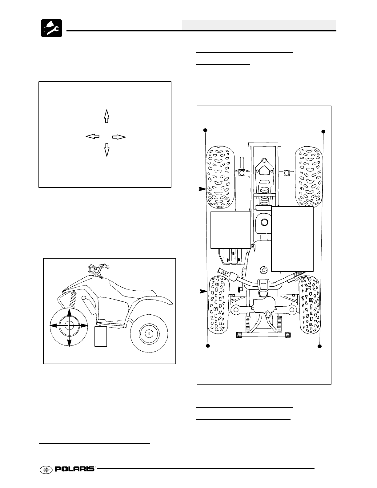
MAINTENANCE
G Replace any worn steering
components. Steering should move
freely through entire range of travel
without binding.
G Elevate front end of machine so front
wheels are off the ground. Checkfor
any looseness in front hub / wheel
assembly by grasping the tire firmly
at top and bottom first, and then at
front andrear. Try to movethewheel
and hub by pushing inward and
pulling outward.
WHEEL ALIGNMENT
METHOD 1:
STRAIGHTEDGE OR STRING
Be sure to keep handlebars centered. See notes
below.
NOTE: String should just touch side surface of rear tire on each side of machine.
Measure
from string
to rim at
front and
rear of rim.
Rear rim
measure-
ment should
be 1/16″ to
1/8″ (.2to.3
cm) more
than front rim
measure-
ment.
Check for Loose Wheel or Hub
G If abnormal movement is detected,
inspect the hub and wheel assembly
to determine the cause (loose wheel
nuts, loose front hub nut (4x4).
G Refer to the Body/Steering or Final
Drive chapter for more information.
CAMBER AND CASTER
The camber and caster are non-adjustable.
NOTE: The steering post arm “frog” can be
used as an indicator of whether the handle-
bars are straight. The frog should always
point straight back from the steering post.
WHEEL ALIGNMENT
METHOD 2:
1. Place machine on a smooth level surface.
2. Set handlebars in a straight ahead position and
secure handlebars in this position. NOTE: The
steering arm “frog” can be used as an indicator of
whether the handlebars are straight. The frog
CHALK
2.31
Page 42
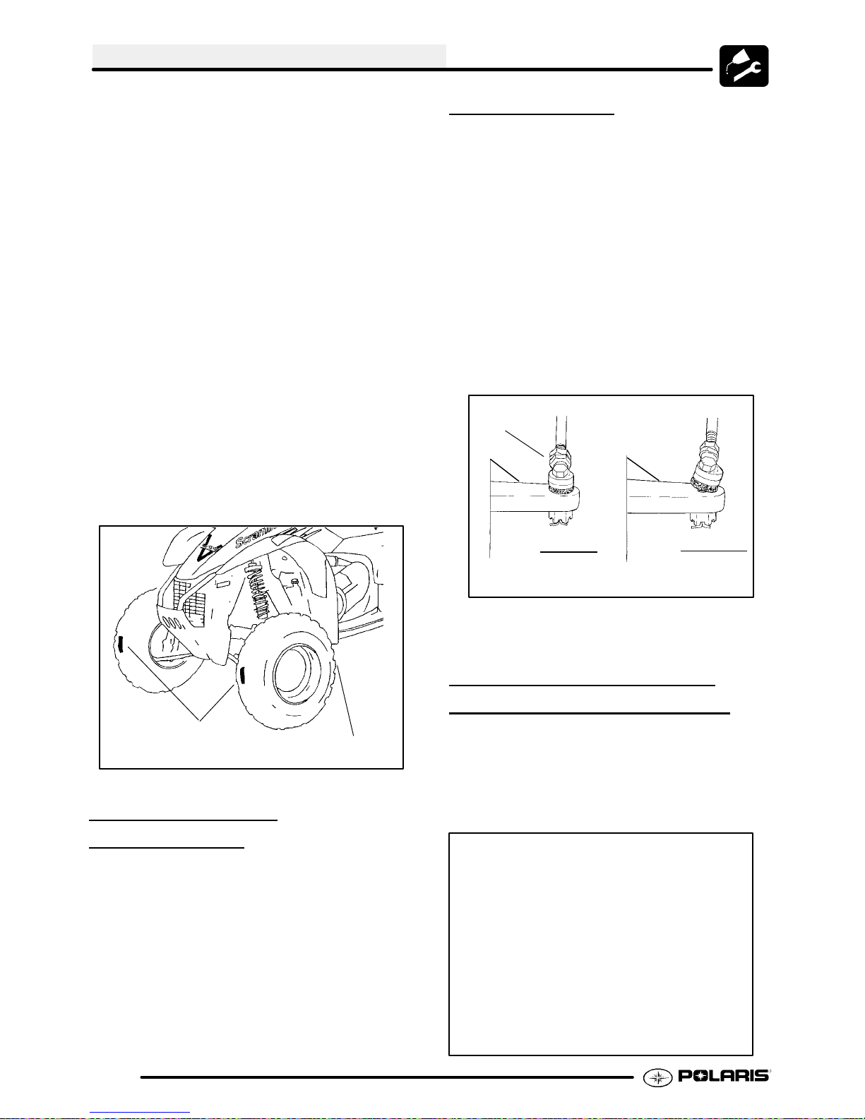
MAINTENANCE
should always point straight back from the
steering post.
3. Place a chalk mark on the center line of the front
tires approximately 10″ (25.4 cm) fromthe floor or
as close to the hub/axle center line as possible.
NOTE: It is important that the height of both
marks be equally positioned in order to get an
accurate measurement.
4. Measure the distance between the marks and
record the measurement. Callthis measurement
“A”.
5. Rotatethetires180° bymovingvehicle forwardor
backward. Position chalkmarks facing rearward,
even with the hub/axle centerline.
6. Again measure the distance between the marks
and record. Callthis measurement “B”. Subtract
measurement “B” from measurement “A”. The
difference between measurements “A” and “B” is
the vehicle toe alignment. The recommended
vehicle toe tolerance is 1/8″ to 1/4″ (.3to.6cm)
toeout. This means themeasurementat the front
ofthe tire (A)is 1/8″ to 1/4″ (.3to .6 cm)wider than
the measurement at the rear (B).
To adjust toe
G Hold tie rod end to keep it from
G Loosenjamnuts atbothendof thetie
G Shorten or lengthen the tie rod until
G Important: When tightening the tie
Hold
Rod End
alignment:
rotating.
rod.
alignmentisasrequir ed to achieve
the proper t oe set ting. M ethod 1
(1/16″ to 1/8″)or Method 2 (1/8″ to
1/4″).
rod end jam nuts, the rod ends must
be held parallel to prevent rod end
damage and premature wear.
Damage may not be immediately
apparent if done incorrectly. See
illustration.
Chalk Line
Measurement
“A”
Measurement “B”
TOE ALIGNMENT
ADJUSTMENT
If toe alignment is incorrect, measure the distance
between vehicle center and each wheel. This will tell
you which tie rod needs adjusting. NOTE: Be sure
handlebars are straight ahead before determining
which tie rod(s) need adjustment.
Correctly
Tightened
Jam Nut
7. After alignment is complete, torque jam nuts to
12-14 ft. lbs. (16-19 Nm).
Incorrectly
Tightened
Jam Nut
FRONT AWD HUB FLUID
LEVEL INSPECTION
To check front hub fluid:
1. Place vehicle on a level surface.
2. Turnwheeluntilfront hubfill/checkplugis in either
the 4:00 or 8:00 position.
3. Remove fill/check plug.
(4X4)
CAUTION: During tie rod adjustment it is very
important that the following precautions be taken
when tightening tie rod end jam nuts. If the rod end
is positioned incorrectly it will not pivot, and may
break.
2.32
Page 43

MAINTENANCE
4. Add Polaris Demand Drive Hub Fluid (PN
2871654) if necessary until fluid trickles out.
NOTE: Do not force the fluid into the hub under
pressure or seal damage may occur.
5. Reinstall plug.
6. Repeat procedure for other hub.
AWD FRONT HUB FLUID
CHANGE
1. Place a drain pan beneath the hub.
2. Remove check/fill plug.
3. Turnthe hubtothe6o’clock position anddrain the
fluid
into the drain pan.
4. Turnwheeluntilfront hubfill/checkplugis in either
the 4 or 8 o’clock position.
5. Add Polaris Demand Drive Hub Fluid until fluid
trickles out. NOTE: Donotforce the fluid into the
hub under pressure or seal damage may
occur.
(4X4)
EXHAUST PIPE
WARNING
G Do not perform clean out immediately
after the engine has been run, as the exhaust system becomes very hot. Serious
burns could result from contact with exhaust components.
G T o reduce fire hazard, make sure that
there are no combustible materials in the
area when purging the spark arrestor.
G Wear eye protection.
G Do not stand behind or in front of the ve-
hicle while purging the carbon from the
spark arrestor.
G Never run the engine in an enclosed
area. Exhaust contains poisonous carbon monoxide gas.
G Do not go under the machine while it is
inclined. Set the hand brake and block
the wheels to prevent roll back.
Failure to heed these warnings could result in
serious personal injury or death.
Polaris Demand Drive Hub Fluid:
(PN 2871654) - 8 oz..
(PN 2872277) - 2.5 gallon
The exhaust pipe must be periodically purged of
accumulated carbon as follows:
1. Remove the clean out plugs located on the
bottom of the muffler as shown in illustration 1.
Ill.1
2. Place the transmission in neutral and start the
engine. Purge accumulated carbon from the
system by momentarily revving the engine
several times.
3. If some carbon is expelled, cover the exhaust
outlet and rap on the pipe around the clean out
plugs while revving the engine several more
times.
4. If particles are still suspected to be in the muffler,
backthe machineonto an inclineso therear of the
machine is one foot higher thanthe front. Set the
hand brake and block the wheels. Make sure the
machine is in neutral and repeat Steps 2 and 3.
SEE WARNING ABOVE
5. If particles are still suspected to be in the muffler,
drive the machine onto the incline so the front of
Clean Out Plug
2.33
Page 44

MAINTENANCE
the machine is one foot higher than the rear. Set
the hand brake and block the wheels. Makesure
the machine is in neutral and repeat Steps 2 and
3. SEE WARNING ABOVE
6. Repeat Steps 2 through 5 until no more particles
are expelled when the engine is revved.
7. Stop the engine and allow the arrestor to cool.
8. Reinstall the clean out plugs.
BRAKE SYSTEM INSPECTION
The following checks are recommended to keep the
brakesystemin goodoperating condition. Service life
of brake system components depends on operating
conditions. Inspect brakes in accordance with the
maintenance schedule and before each ride.
G Keepfluidlevel inthe master cylinder
reservoir to the indicated level inside
reservoir.
G Use Polaris DOT 3 Brake Fluid (PN
2870990).
Sight
Glass
Parking Brake
Lock
BRAKE PAD INSPECTION
3/64″
(.1cm)
Minimum
Thickness
G Pads should be changed when
friction material is worn to 3/64″ (.1
cm),or aboutthethickness ofadime.
HOSE/FITTING INSPECTION
Check brake system hoses and fittings for cracks,
deterioration, abrasion, and leaks. Tighten any loose
fittings and replace any worn or damaged parts.
Rear Master Cylinder Reservoir
Max
Min
G Check brake system for fluid leaks.
G Check brake for excessive travel or
spongy feel.
G Check friction pads for wear,
damage or looseness.
G Check surface condition of the disc.
G Inspect thickness of brake pad
frictionmaterial.
AUXILIARY BRAKE
ADJUSTMENT
Use the following procedure to inspect the hydraulic
auxiliary (foot) brake system and adjust or bleed if
necessary:
First, checkfootbrake effectiveness byapplying50lb.
(approx.) downwardforce onthe pedal. The top of the
pedal should be at least 1 inch, (25.4mm) above the
surface of the footrest.
1/8, to 1/4,
Free Play
(HYDRAULIC)
50 lbs
1″ or greater
Floorboard
2.34
Page 45
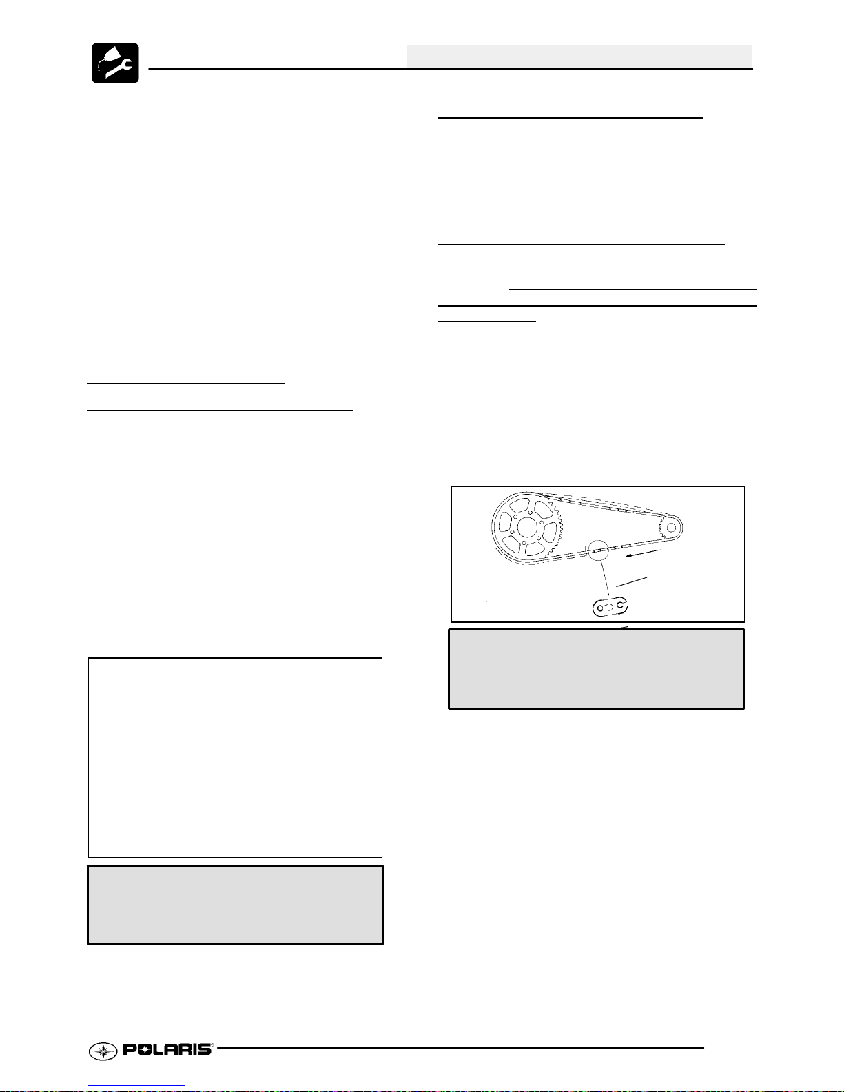
MAINTENANCE
If less than one inch, two things must be examined:
Free Play:
Free play of the brake pedal should be 1/8 - 1/4
inch (3.2 - 6.35 mm).
If free play is excessive, inspect pedal, linkage, and
master cylinder for wear or damage and replace any
parts as needed.
Bleeding:
If free play is correct and brake pedal travel is still
excessive, air may be trapped somewhere in the
system. Bleed the hydraulic auxiliarybrakesystem in
a conventional manner, following the procedure
outlined in Brake Chapter 9.
DRIVE CHAIN AND
SPROCKET
Polaris ATV drive chains are equipped with O-ring
sealed permanently greased pins and rollers. The
sprockets and outer rollers require periodic
lubrication. Lubricate the chain with Polaris O-Ring
Chain Lubricant (PN 2872073).
INSPECTION
SPROCKET INSPECTION
Inspect the sprocket for worn, broken or bent teeth.
To check for wear, pull outward on the chain as
shown. Replacesprocket if chainmovementexceeds
1/4″ (.6 cm).
DRIVE CHAIN INSPECTION
The chain must be replaced when it reaches 3%
elongation. The chain master link is a press--on
that requires a chain pressing tool to install
remove the
1. Stretch the chain tightly in a straight line.
2. Measurealength oftwentypitches(pins) from pin
center to pin center, and compare to the
specification. Replace the chain if the length
exceeds the wear limit.
3. When replacing or reinstalling drive chain, install
theclosed end ofthe splicelink clipasshown,with
the closed end leading in forward operation.
link.
style
and
Inspect the drive chain for missing or damaged
O-Rings, link plates, or rollers. Donotwashthechain
with a high pressure washer, gasoline or solvents; do
not use a wire brush to clean the chain as damage to
the O-Rings may occur. Clean chain with hot soapy
water and a soft bristled nylon brush.
Never allow battery acid to contact the drive chain.
Service Limit:
1/4″ (6mm)
Drive Chain Lubricant:
Polaris O-Ring Chain Lubricant
(PN 2872073)
Proper
Splicelink Clip
Opening
Position
Drive Chain Wear Limit-- 20 Pitch Length:
Std: 12.5″ (32 cm)
Wear Limit: 12.875″ (32.7 cm)
.003--.005”
(.076--.127 mm)
Gap after installation
2.35
Page 46
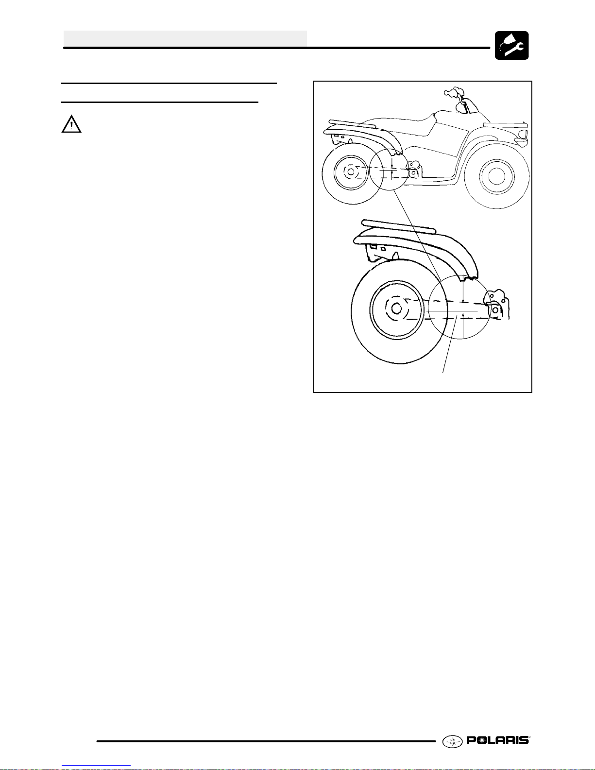
MAINTENANCE
DRIVE CHAIN ADJUSTMENT,
CONCENTRIC
CAUTION: Never adjust or operate the vehicle
with the rear drive chain too loose or too tight as
severe damage to the transmission and drive
components can result.
Break-In: Itis extremely importantto maintain proper
chain tension to ensure the best possible chain life.
There is a chain break-in period of approximately 100
miles or two (2) tanks of fuel. During this time chain
tension should be watched very closely and loads to
the chain should be kept light.
Checking Deflection: Inspect chain deflection by
slowly moving theATV forward so any slack that may
have previously been on the under part of the chain
is now on the top side of the chain. The bottom part
of the chain should be taught during inspection.
Measure the chain deflection as shown in the
diagram. Deflection should be approximately3/8
in. (10 mm). After inspection, again slowly move the
ATVforward until all the chain slack is onthe top side
of the chain and inspect the deflection. Repeat this
procedure several times to check different spots on
the chain.
The chain is correctly adjusted when the tightest
portionof thechain itself hasapproximately3/8in.,(10
mm) ofdeflection. It’sa commoncharacteristic of any
chain to have one or more tight spots in the chain.
Therefore, it is extremely important to check chain
deflection in several areas of the chain to ensure
deflection is correct at the tightest point.
SWINGARM
3/8″ (10 mm) Deflection
2.36
Page 47
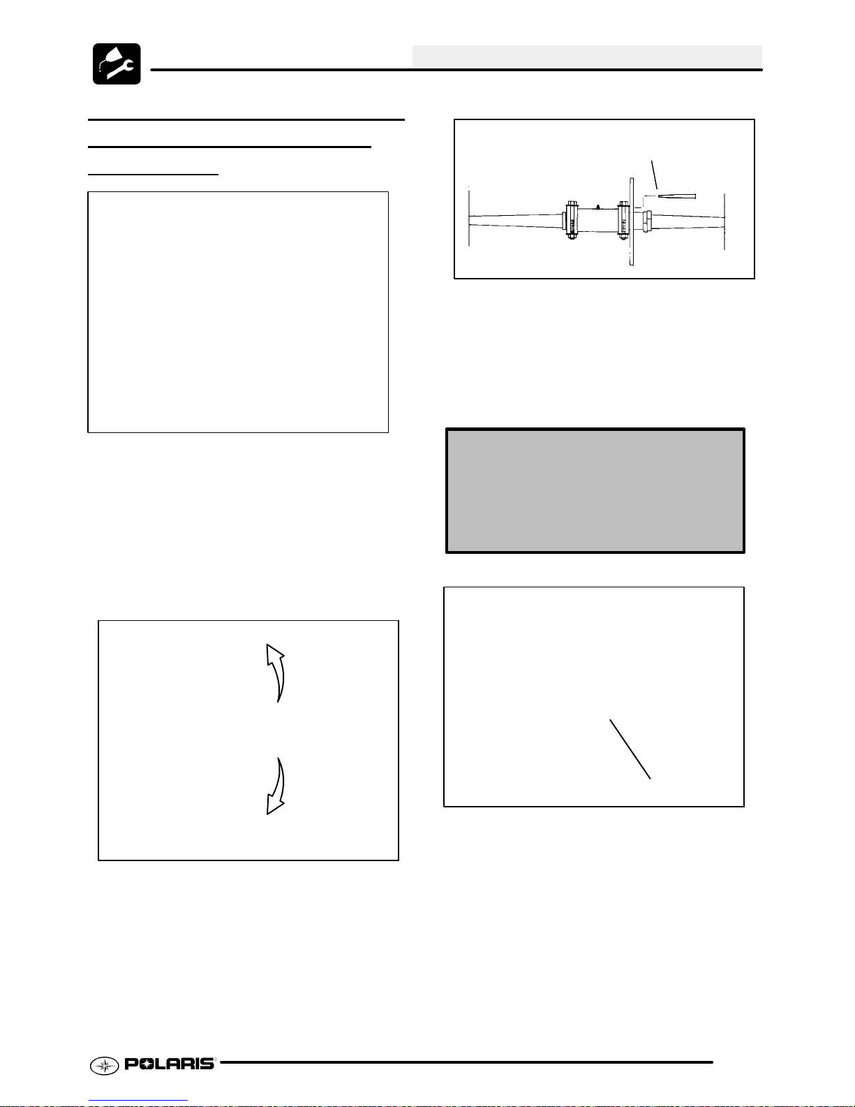
ADJUSTMENT PROCEDURE CONCENTRIC
REAR
AXLE
SWINGARM
Loosen Eccentric
clamp bolts (Step 2)
MAINTENANCE
Alternate Adjustment Method -- Pin Punch
(Step 5 and 6)
6. Roll the vehicle ahead or back to adjust chain
slack to the proper dimension.
7. Tightenthe eccentric clampbolts tospecification.
Loosen (2) caliper
mounting bracket
bolts (Step 3 --
2004 models)
1. Loosen chain guard.
2. Loosen two eccentric clamp bolts.
3. 2004 Models -- Loosen caliper mounting bracket
bolts.
4. Using a 2 1/2″ wrench, rotate the housing to
adjust chain slack to the proper dimension, and
then proceed to Step 7; or... follow Steps 5 and
6 for alternate method if 2 1/2″ wrench is not
available.
Loosen
CAUTION: DO NOT OVER-TIGHTEN
ECCENTRIC CLAMP BOLTS. PREMATURE
BEARING FAILURE MAY RESULT.
Eccentric Clamp Bolt Torque Specs
Pinch Clamp Bolt Torque --
30 ft. lb s. (41 Nm)
Pinch Clamp Bolt Torque
w/ Trailer Hitch -- 40 ft. lbs. (54 Nm)
Eccentric Clamp Without Hitch
Tighten
5. Insert a pin punch through the sprocket hub and
into the eccentric axle housing.
30 ft.lbs. (41 Nm)
Without Trailer Hitch
2.37
Page 48
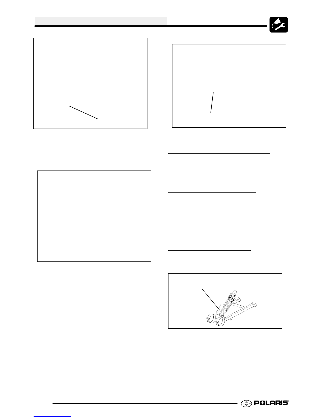
MAINTENANCE
Eccentric Clamp With Hitch
Torque to 40 ft.lbs. (54 Nm)
Chain Guide
With Trailer Hitch
8. Remove the pin punch.
9. 2004 Models -- Tighten caliper mounting bracket
bolts 10-12 ft. lbs. (14 - 17 Nm).
2004 Models: Caliper Mount Bracket
10-12 ft. lbs
10. Verify chain adjustment is correct after tightening
eccentric clamp bolts to specification by rolling
ATV forward and checking chain tension in
several places on chain. The chain is adjusted
correctly when the tightest portion of the
chain has approximately 3/8 in. (10 mm) of
deflection.
1 1. Reinstall the chain guard (where applicable).
Reposition chain guide to allow 1/8″ (.3 cm)
clearance between sprocket and guide.
SUSPENSION SPRING
PRELOAD
Operator weight and v ehicle loading affect
suspensionspringpreloadrequir ements.Adjus tas
necessary.
ADJUSTMENT
FRONT SUSPENSION
Compress and release front suspension. Damping
should be smooth throughout the range of travel.
Check all front suspension components for wear or
damage.
Inspect front strut cartridges for leakage.
REAR SUSPENSION
Compress and release rear suspension. Damping
should be smooth throughout the range of travel.
Rear Spring
Adjustment Cam
2.38
G Check all rear suspension
components for wear or damage.
G Inspect shock for leakage.
REARSHOCK: Use the ShockSpanner Wrench(PN
2870872) to adjust the shock preload cam.
Page 49

MAINTENANCE
CV SHAFT BOOT
INSPECTION
Inspect the cv shaft boots in the front of the ATV for
damage, tears, wear, or leaking grease. If the rubber
boot exhibits any of these symptoms, replace the
boot. Refer toChapter 7 for CV boot replacement, or
have you Polaris dealer replace the boot.
Inspect Boots
CONTROLS
Check controls for proper oper ation, posit ioning
and adjustment .
WHEEL, HUB, AND SPINDLE
TORQUE T
Item Specification
Front Wheel Nuts 27 Ft. Lbs. (27 Nm)
Rear Wheel Nuts 50 Ft. Lbs. (68 Nm)
Front Spindle Nut Referto procedure listed in
Rear Hub Retaining Nut 80 Ft. Lbs. (108 Nm)
ABLE
Chapter 7
WHEEL REMOVAL FRONT OR
REAR
1. Stop the engine, place the transmission in gear
and lock the parking brake.
2. Loosen the wheel nuts slightly.
3. Elevate the side of the vehicle by placing a
suitable stand under the footrest frame.
4. Remove the wheel nuts and remove the wheel.
Front Wheel
Front Spindle Nut
See Ch. 7
G Brake control and switch must be
positioned to allow brake lever to
travel throughout entire range
without contacting switch body.
WHEELS
Inspect all wheelsfor runout or damage. Checkwheel
nuts and ensure they aretight. Donot over tightenthe
wheel nuts.
Front Wheel Nuts (4)
27 ft. lbs. (34 Nm)
Rear Wheel
Rear Wheel Nuts (4)
50 ft. lbs. (68 Nm)
Taper end faces
wheel for install.
Rear Hub Nut
80 ft. lbs. (108 Nm)
2.39
Page 50

MAINTENANCE
WHEEL INSTALLATION
1. With the transmission in gear and the parking
brake locked, place the wheel in the correct
positiononthewheelhub. Besure thevalvestem
is toward the outside and rotation arrows on the
tire point toward forward rotation.
2. Attach the wheel nuts and finger tighten them.
3. Lower the vehicle to the ground.
4. Securely tighten the wheel nuts to the proper
torque listed in the table above.
CAUTION:
If wheels are improperly installed it could affect
vehicle handling and tire wear. On vehicles with
taperedrear wheelnuts, makesuretaperedend ofnut
goes into taper on wheel.
TIRE PRESSURE
Tire Pressure Inspection (PSI - Cold)
Front Rear
4 3
Tread
Depth 1/8I (3 mm)
WARNING
Operating an ATVwith worntires willincrease
the possibility of the vehicle skidding and possible loss of control.
Worn tires can cause an accident.
Always replace tires when the tread depth
measures 1/8″ (.3 cm) or less.
FRAME, NUTS, BOLTS,
ASTENERS
F
TIRE INSPECTION
CAUTION:
G Maintain proper tire pressure. Refer
to the warning tire pressure decal
applied to the vehicle.
G Impropertire inflationmayaffect ATV
maneuverability.
G When replacing a tire always use
original equipment size and type.
G Theuseof non-standard size or type
tires may affect ATV handling.
Tire Tread Depth
Always replace t ires when tread depth is worn to
1/8″ (3 mm) or less.
Periodically inspect the tightness of all fasteners in
accordance with the maintenance schedule. Check
that all cotter pins are in place. Refer to specific
fastener torques listed in each chapter.
2.40
Page 51

Torque Specifications 3.2........................
EH50PL Service Data 3.3-3.4........................
Special Tools 3.5...............................
Torque Patterns 3.5.............................
Piston Identification 3.5..........................
Cooling System Bleeding Procedure 3.6...........
Cooling System Tests/Routing/Specifications 3.7...
Engine Removal 3.8............................
Engine Installation Notes 3.8-3.9.....................
Cylinder Honing 3.9.............................
Crankshaft Runout Inspection/Straightening 3.10....
EH50PL Engine Lubrication 3.10..................
EH50PL Oil Pump Priming Procedure 3.11..........
EH50PL Lubrication/Oil Flow 3.11.................
EH50PL Engine Oil Flow charts 3.12...............
EH50PL Engine Exploded Views 3.13..............
EH50PL Engine Top End Disassembly 3.14 -3.23.........
EH50PL Valve Seat Service 3.23-3.26..................
EH50PL Cylinder Head Assembly 3.26-3.27.............
EH50PL Cylinder Service 3.27-3.31....................
EH50PL Engine Bottom End Disassembly 3.31-3.37......
EH50PL Crankcase & Bearing Assembly 3.37--3.38.......
EH50PL Crankshaft End Play Inspection 3.38-3.39.......
EH50PL Counter Balancer End Play Inspection. 3.40.
EH50PL Oil Pump Shaft End Play Inspection 3.40--3.41...
EH50PL Engine Assembly/Inspection 3.41-3.51..........
Sealed Recoil Disassembly/Inspection 3.51--3.52.........
Sealed Recoil Assembly 3.52.....................
Spark Plug Fouling Checklist 3.53.................
Troubleshooting 3.53--3.54.............................
ENGINE
3.1
Page 52
ENGINE
TORQUE SPECIFICATIONS
TORQUE SPECIFICATIONS
Fastener Size EH50PLE
Ft. Lbs. (Nm)
Blind Plug (Oil Pressure) 1/8 Pipe
Thread
Camshaft Sprocket 6mm 5-6.5 (7-9 Nm)
Camshaft Chain T ensioner Lever 6mm 5-6.5 (7-9 Nm)
Camshaft Chain T ensioner 6mm 5-6.5 (7-9 Nm)
Camshaft Chain T ensioner Cap 11mm 14-19 (20-25 Nm)
Carburetor Adaptor 8mm 12-14 (16-20 Nm)
Crankcase 8mm 14-15 (19-21 Nm)
Crankshaft Slotted Nut (Cam Chain Drive Sprocket) 28mm 35-51 (47-69 Nm)
Cylinder Base Bolts 10mm
6mm
Cylinder Head Bolts 11mm
6mm
Drive Clutch Bolt 7/16 - 20 40 (55 Nm)
Flywheel 16mm 58-72 (78-98 Nm)
Oil Delivery Pipe 12mm 11-15 (15-21 Nm)
Oil Drain Bolt (Crankcase) 14mm 14-17 (19-23 Nm)
Oil Filter Pipe Fitting 20mm 36-43 (49-59 Nm)
Oil Hose Fitting 1/8 Pipe
Thread
Hard Metal Oil Line Banjo Fitting N/A 11--16 ft. lbs.
Oil Pump 6mm 5-6.5 (7-9 Nm)
Oil Pump Case Screw 5mm 1.5-2 (2-3 Nm)
One Way Valve 11mm 14-19 (20-25 Nm)
Recoil Housing 6mm 5-6.5 (7-9 Nm)
Rocker Cover 6mm 7-8 (9-11 Nm)
Rocker Support 8mm 8-10 (1 1-13 Nm)
Rocker Adjuster Screw 6mm 6-7 (8-10 Nm)
Water Pump Impeller Nut 6mm 5-6.5 (7-9 Nm)
Water Pump Housing Cover 6mm 5-6.5 (7-9 Nm)
Stator Plate 6mm 5-6.5 (7-9 Nm)
Starter Motor 6mm 5-6.5 (7-9 Nm)
Spark Plug 14mm 9-11 (12-15 Nm)
Thermistor -- -- 26 ± 2.1 (35 ± 3
6.5-11 (9-15 Nm)
45-49 (61-67 Nm)
6-8 (9-11 Nm)
Refer to Engine
Assembly for
torque procedure
6.5-11 (9-15 Nm)
(15--21 Nm)
Nm)
3.2
Page 53

EH50PLE ENGINE SERVICE DATA
g
j
j
y
g
g
g
pgg
Cylinder Head / Valve EH50PLE10
Rocker Arm
Camshaft Cam lobe height In
Cylinder Head
Valve Seat Contacting width In
Valve Guide
Valve Margin thickness In
Valve
Valve Spring Overall length
Rocker arm ID .8669-.8678″ (22.020-22.041 mm)
Rocker shaft OD .8656-.8661″ (21.987-22.0 mm)
Rocker shaft Oil Clear-
ance
Camshaft journal OD
Camshaft journal bore ID
Camshaft Oil clearance
Surface warpage limit .0020″ (.05 mm)
Standard height 3.870″ (98.3 mm)
Inner diameter .2362-.2367″ (6.0-6.012 mm)
Protrusion above head .689-.709″ (17.5-18.0 mm)
Stem diameter In .2343-.2348″ (5.950-5.965 mm)
Stem oil clearance Std
Overall length
Squareness .075″ (1.9 mm)
Std .0008-.0021″ (.020-.054 mm)
Limit .0039″ (.10 mm)
Std 1.2884-1.2924″ (32.726-32.826 mm)
Limit 1.2766″ (32.426 mm)
Ex
Std 1.2884-1.2924″ (32.726-32.826 mm)
Limit 1.2766″ (32.426 mm)
Mag 1.4935-1.4941″ (37.935-37.950 mm)
PTO 1.4935-1.4941″ (37.935-37.950 mm)
Mag 1.4963-1.4970″ (38.005-38.025 mm)
PTO 1.4963-1.4970″ (38.005-38.025 mm)
Std .0022-.0035″ (.055-.090 mm)
Limit .0039″ (.10 mm)
Std .028″ (.7 mm)
Limit .055″ (1.4 mm)
Ex
Std .039″ (1.0 mm)
Limit .071″ (1.8 mm)
Std .039″ (1.0 mm)
Limit .031″ (.8 mm)
Ex
Std .047″ (1.2 mm)
Limit .031″ (.8 mm)
Ex .2341-.2346″ (5.945-5.960 mm)
In .0014-.0024″ (.035-.062 mm)
Ex .0016-.0026″ (.040-.067 mm)
Limit .0059″ (.15 mm)
In 3.976″ (101.0 mm)
Ex 3.984″ (101.2 mm)
Std 1.654″ (42.0 mm)
Limit 1.575″ (40.0 mm)
ENGINE
3.3
Page 54

ENGINE
g
g
p
g
g-p
groov
e
g
g
g
g
g
g
EH50PLE ENGINE SERVICE DATA
Cylinder / Piston / Connecting Rod EH50PLE10
Cylinder
Piston Outer diameter
Piston Pin
Piston Ring Piston ring installed Top
Piston Ring Standard clearance Top
Connecting
Rod
Crankshaft Crankshaft runout limit .0024″ (.06 mm)
Surface warpage limit (mating with
cylinder head)
Cylinder bore Std 3.6221-3.6228″ (92.00-92.02 mm)
Taper limit .0020″ (.050 mm)
Out of round limit .0020″ (.050 mm)
Piston clearance
Boring limit .020″ (.5 mm)
Std 3.6204-3.6215″ (91.970-91.985 mm)
.0098″ (.25
mm) OS
.0197″ (.50
mm) OS
Standard inner diameter of piston
pin bore
Outer diameter .9053-.9055″ (22.994-23.0 mm)
Standard clearance-piston pin to pin
bore
Degree of fit Piston pin must be a push (by hand) fit
gap
piston ring to ring
Connecting rod small end ID .9058-.9063″ (23.007-23.020 mm)
Connecting rod small end ra-
dial clearance
Connecting rod big end side
clearance
Connecting rod big end radial
clearance
ring
Second
ring
Oil ring
ring
Second
ring
Std .0006-.0018″ (.015-.045 mm)
Limit .0024″ (.060 mm)
Std .0079-.0138″ (.20-.36 mm)
Limit .039″ (1.0 mm)
Std .0079-.0138″ (.20-.36 mm)
Limit .039″ (1.0 mm)
Std .0079-.0276″ (.20-.70 mm)
Limit .059″ (1.5 mm)
Std .0016-.0031″ (.040-.080 mm)
Limit .0059″ (.15 mm)
Std .0012-.0028″ (.030-.070 mm)
Limit .0059″ (.15 mm)
Std .0003-.0010″ (.007-.026 mm)
Limit .0020″ (.05 mm)
Std .0039-.0256″ (.1-.65 mm)
Limit .0315″ (.80 mm)
Std .0004-.0015″ (.011-.038 mm)
Limit .0020″ (.05 mm)
.0020″ (.05 mm)
3.6304-3.6310 (92.21-92.23 mm)
3.6403-3.6407 (92.46-92.47 mm)
.9055-.9057″ (23.0-23.006 mm)
.0002-.0003″ (.004-.008 mm)
at 68° F(20° C)
KEY- Std: Standard;OS: Oversize; ID: InnerDiameter;
OD: Outer Diameter;Mag: MagnetoSide; PTO: Power
Take Off Side
3.4
Page 55
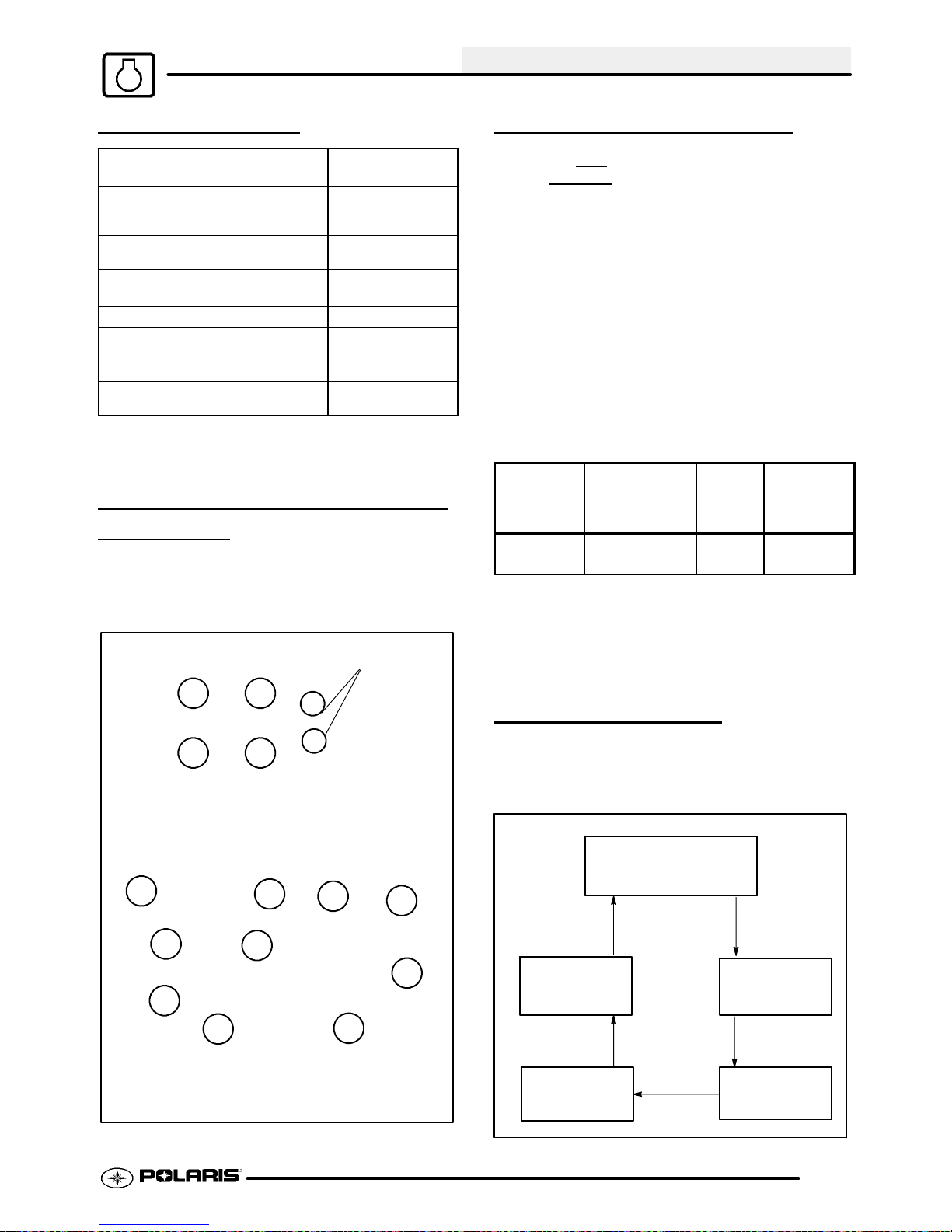
ENGINE
SPECIAL TOOLS
PART NUMBER TOOL
DESCRIPTION
2872105 Water Pump
2200634 Valve Seat
2870390 Piston Support
2871043 Flywheel Puller
2871283 Crankshaft/Water
5131135 Water Pump
Mechanical Seal
Puller
ReconditioningKit
Block
Pump Seal Install
Kit
Install Kit
ENGINE FASTENER TORQUE
TTERNS
PA
Tighten cylinder head, cylinder base, and crankcase
fasteners in 3 steps following the sequence outlined
below.
PISTON IDENTIFICATION
Thepistonmay havean identification mark or the
piston may not
piston placement. If the piston has an identification
mark, follow the directions for piston placement
below. If the piston does not have an identification
mark, the direction for placement of the piston does
not matter.
Note the directional and identification marks when
viewing the pistons from the top. The letter “F”, “ !
”, “ "”or: must always be toward the flywheel side
of the engine. The other numbers are used for
identification as to diameter, length and design. Four
stroke engine rings are rectangular profile. See text
for oil control ring upper rail installation. Use the
information below to identify pistons and rings.
Engine
Model No.
EH50PLE10 .25
*Pistons and rings marked 25 equal .25mm (.010I)
oversized
have an identification mark for
Oversize
Available*
(mm)
.50
Piston
Length
72mm C
Standard
Piston
Identifier
6mm
23
1
Cylinder Head
Cylinder Base
4
Pattern
7
3
1
5
6
5
9
10
8
2
4
6
Crankcase
Pattern
Pistons and rings marked 50 equal .50mm (.020I)
oversized
COOLING SYSTEM
WARNING: Neverremove radiator cap when engine
is warm or hot. Thecooling system is under pressure
and serious burns may result. Allow the engine and
cooling system to cool before servicing.
FLOW
Radiator
Thermostat
Cylinder
Head
Water
Pump
Cylinder
3.5
Page 56

ENGINE
COOLING SYSTEM -- 4--STROKE BLEEDING PROCEDURE
Use this procedure when a unit overhea ts and no apparent leaks in the cooling system are found.
Note: If the coolant level is LOW in the radiator, or if there
are leaks in the system, the coolant system will not draw
coolant from the reservoir tank.
1. Park Machine on a flat surface. Remove radiator cap and
top off coolant. Leave the cap off of the radiator. Start and idle
machine for 5-10 minutes until steam is visible in the radiator
cap area.
2. Stop the engine and let cool for a few minutes or until a
bubble is seen at the filler neck or there is a dropping of the
coolant level, indicating that coolant has been pulled into the
system.
ImportantTips: Slowly squeezing the hose after the bend
below the filler neck will aid in purging the system of air.
Pump the hose using your hand several times as shown in
the diagram. Elevating the rear of the ATV with a floor jack
(rear tires 4-6, off the ground) also aids the purging of air from
the system.
Squeeze Hose
Here to Help
Purge Air From
System
Pump hose by
hand to help
purge system
3. Always add coolant to the radiator first,
the neck to replace air that has been purged from the system.
Fill the reservoir only after you have completely filled the coo
ing system at the radiator filler neck
4. Repeat Steps 1 and 2 four or five times or until no more
coolant is pulled into the system.
5. In some instances, Steps 1 and 2 may have to be performed with the radiator cap on to prevent coolant loss.
6. T o test, install the radiator cap and idle machine until fan
comes on. Make sure the fan comes on before the hot light.
.
filling to the top of
Remote Filler Coo ling System
Polaris Premium Antifreeze
l-
2871534 Quart
2871323 Gallon
3.6
Page 57

ENGINE
RADIATOR CAP / SYSTEM
PRESSURE
1. Remove radiator cap and test using a cap tester
(commercially available).
2. The radiator cap relief pressure is 13 lbs. for all
models.
COOLING SYSTEM
TEST
Pressure test
here with cap
in place
Radiator
Front
View
COOLING SYSTEM
SPECIFICA
THERMISTOR READING DURING OPERA
Condition
Hot Light
On
Fan Off 296Ω -- 316Ω 180° F(82° C)
Fan On 236Ω -- 251Ω 195° F(91° C)
System
Capacity
Radiator
Cap Relief
Pressure
TIONS
Thermistor
26 ± 2.1 ft.lbs.
(35 ± 3Nm)
Approx. Reading
(Min--Max)
178Ω -- 190Ω 215° F
2.25 Quarts
(2.13L)
Temperature
(102° C)
13 PSI
TION
Vent hole inside cap
liner must be clear.
RECOMMENDED COOLANT
Use only high quality antifreeze/coolant mixed with
distilled water in a 50/50 or 60/40 ratio, depending on
freeze protection required in your area. CAUTION:
Using tap water in the cooling system will lead to a
buildup of deposits which may restrict coolant flow and
reduce heat dissipation, resulting in possible engine
damage. Polaris Premium 60/40 Antifreeze/Coolant is
recommendedfor usein all coolingsystems, andcomes
pre-mixed and ready to use.
3.7
Page 58

ENGINE
ACCESSIBLE COMPONENTS
The following components can be serviced or
removed with the engine installed in the frame:
S Flywheel
S Alternator/Stator
S Starter Motor/Starter Drive
S Cylinder Head
S Cylinder
S Piston/Rings
S Camshaft
S Rocker Arms
S Cam Chain and Sprockets
S Water Pump / Water Pump
Mechanical Seal*
The following components require engine
removal for service:
S Oil pump / Oil Pump Drive Gear
S Counterbalance Shaft or Bearing(s)
S Connecting Rod
S Crankshaft
S Crankshaft Main Bearings
S Crankcase
*It may be necessary to loosen engine mounts and
move engine slightly to access water pump. Use the
WaterPump Mechanical Seal Puller (PN 2872105)to
replace mechanical seal with engine in frame.
ENGINE REMOVAL
1. Clean work area.
2. Thoroughly clean the ATV engine and chassis.
3. Disconnect battery negative (-) cable.
4. Remove the following parts as required.
S Seat
S Left and Right Side Covers (Refer to
Chapter 5)
S Fuel T ankCover / Front Cab (Refer to
Chapter 5)
S Fuel T ank (Refer to Chapter 4)
5. Disconnect spark plug high tension lead.
6. Remove springs from exhaust pipe and remove
pipe.
7. Drain coolant and engine oil.
8. Remove air pre-cleaner and duct.
9. Remove airbox.
10. Remove carburetor. Insert a shop towel into the
carburetor flange to prevent dirt from enteringthe
intake port.
1 1. Remove center chain guard on chain drive AWD
models.
12. Remove center drive and driven sprocket bolts
andremovechain and sprockets as an assembly.
13. Refer to PVT System to remove outer clutch
cover, drive belt, drive clutch, driven clutch, and
inner cover.
14. Starter motor. Note ground cable location. Mark
positive (+) cable mounting angle and remove
cable.
15. Remove transmission linkage rod(s) from gear
selector and secure out of the way .
16. Disconnect coolant temperature sensor wire.
17. Remove engine to chassis ground cable.
18. Remove all engine mount nuts and / or engine
mount plates.
19. Remove engine through right side of frame.
ENGINE INSTALLATION
NOTES
After the engine is installed in the frame, review this
checklist and perform all steps that apply.
General Items
1. Install previously removed components using
new gaskets, seals, and fasteners where
applicable.
2. Perform regular checks on fluid levels, controls,
and all important areas on the vehicle as outlined
in the daily pre-ride inspection checklist (refer to
Chapter 2 or the Owner’s Safety and
Maintenance Manual).
PVT System
1. Adjust center distance of drive and driven clutch.
(Chapter 6)
2. Adjust clutch offset, alignment, and belt
deflection. (Chapter 6)
3. Cleanclutchsheavesthoroughlyand inspectinlet
and outlet ducts for proper routing and sealing.
(Chapter 6)
Transmission
1. Inspecttransmissionoperation andadjust linkage
if necessary. Refer to Chapter 2 and Chapter 8.
Exhaust
1. Replaceexhaust gaskets. Seal connections with
high temp silicone sealant.
2. Checkto besureall springs are in goodcondition.
Bleed Cooling System
1. Remove radiator cap and slowly add coolant to
top of filler neck.
2. Fill coolant reservoir tank to full mark.
3.8
Page 59

ENGINE
3. Install radiator cap and squeeze coolant lines to
force air out of system.
4. Againremoveradiator capandslowlyaddcoolant
to top of fill neck.
5. Start engine and observe coolant level in the
radiator. Allow air to purge and top off as
necessary. Reinstall radiator cap and bring
engine to operating temp. Check level in
reservoir tank after engineis cooland addcoolant
if necessary.
Engine Break In Period
4 Cycle Engine Break-In Period is defined as the first
10 hours of engine operation, or 2 full tanks of fuel.
1. Use only Polaris Premium 4 All Season synthetic
oil, or API certified “SH” oil. Never substitute or mix
oil brands. Serious engine damage can result.
2. Use fuel with a minimum octane of 87 (R+M)/2
method.
3. Change break-in oil and filter at 20 hours or 500
miles, whichever comes first.
CYLINDER HONE
SELECTION/HONING
PROCEDURE
CAUTION:
Selecting a hone which will straighten as well as
remove material from the cylinder is very important.
Using a common spring loaded finger type glaze
breaker for honing is never advised. Polaris
recommends using a rigid hone or arbor honing
machine which also has the capability of oversizing.
Cylinders may be wet or dry honed depending upon
the hone manufacturer’s recommendations. Wet
honing removes more material faster and leaves a
more distinct pattern in the bore.
piston-to-cylinder clearance specifications on Page
3.4 before honing. Complete the sizing with fine grit
stones to provide the proper cross-hatch finish and
required piston clearance.
EXAMPLE OF CROSS HATCH PATTERN
A finished cylinder should have a cross-hatch pattern
toensurepiston ringseatingand toaid inthe retention
of the fuel/oil mixture during initial break in. Hone
cylinder according to hone manufacturer’s
instructions, or these guidelines:
S Use a motor speed of approximately
300-500 RPM, run the hone inand out of
the cylinder rapidly until cutting tension
decreases. Remember to keep the hone
driveshaft centered (orcylinder centered
on arbor) and to bring the stone
approximately 1/2″ (1.3 cm) beyond the
bore at the end of each stroke.
S Release the hone at regular intervals and
inspect the bore to determine if it has been
cleared, andto check piston fit. NOTE: Do
not allow cylinder to heat up during honing.
The thinner areas of the liner around the
ports will expand causing uneven bore.
S After honing has been completed inspect
all port opening areas for rough or sharp
edges. Applya slight chamfer to all ports
to remove sharp edges or burrs, paying
particular attention to the corners of the
intake and exhaust ports.
HONING TO OVERSIZE
CAUTION: If cylinder wear or damage is excessive, it
will be necessary to oversize the cylinder using a new
oversize piston and rings. This may be accomplished
byeither boring the cylinder and then finish honing to the
final bore size, or by rough honing followed by finish
honing.
CAUTION: For oversize honing always wet hone
using honing oil and a coarse roughing stone.
Measure the piston (see piston measurement) and
rough hone to the size of the piston. Always leave
.002 - .003″ (.05 - .07 mm) for finish honing. Refer to
CLEANING THE CYLINDER
AFTER
It is very important that the cylinder be thoroughly
cleanedafterhoning to remove allgritmaterial. Wash
thecylinderin asolvent, then in hot, soapywater. Pay
close attention to areas where the cylinder sleeve
meets the aluminum casting(transfer port area). Use
electrical contact cleaner if necessary to clean these
areas. Rinse thoroughly, dry with compressed air ,
and oil the bore immediately with Polaris 4 Cycle
Lubricant.
HONING
3.9
Page 60
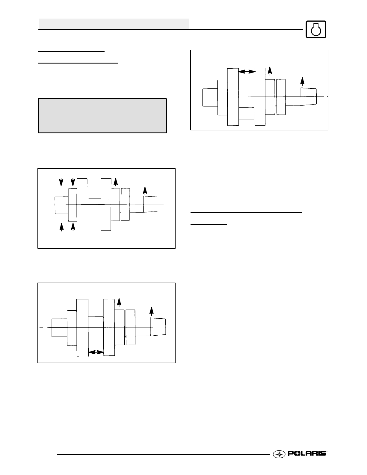
ENGINE
CRANKSHAFT
STRAIGHTENING
Lubricate the bearings and clamp the crankshaft
securely in the Crankshaft Truing Stand (PN
2870569). Refer to the illustrations below.
Crankshaft Truing Stand
(PN 2870569)
NOTE: The rod pin position in relation to the dial
indicator position tells you what action is required to
straighten the shaft.
HIGH .004 (.1mm)
A
B
SUPPORT CRANKSHAFT
HERE.
1. To correct a situation like the one shown in the
illustration at right, strikethe shaft at pointA witha
brass hammer.
HIGH .004 (.1mm)
HIGH .002 (.05mm)
A
3. If the crank rod pin location is 180_ from the dial
indicator (opposite that shown above), it will be
necessary to spread the crankshaft at position A
as shown in the illustration at right. When
rebuilding and straightening a crankshaft, runout
must be as close to zero as possible.
NOTE: Maximum allowable runout is .0024I.
A
HIGH .005 (.13mm)
ENGINE LUBRICATION EH50PL
Oil Type Polaris Premium 4 Synthetic.............
(PN 2871281)
Capacity Approximately 2 U.S.............
Quarts (1.9 l)
Filter (PN 3084963)................
Filter Wrench (PV--43527)........
HIGH .002 (.05mm)
HIGH .005 (.13mm)
AA
2. To correct a situation like the one shown in the
illustration at right, squeeze the crankshaft at
point A. (Use tool from alignment kit).
3.10
*Drain Plug / Screen Fitting 14 ft.lbs. (19 Nm) (If..
fitting is removed, follow oil pump priming procedure).
*Oil Pressure Specification 20 PSI @ 5500...
RPM, Polaris 0W--40 Synthetic (Engine Hot)
Page 61

ENGINE
V
OIL PRESSURE TEST EH50PL
1. Remove blind plug on front left cylinder head.
2. Insert a 1/8 NPT oil pressure gauge adaptor into
the cylinder head and attach the gauge.
3. Start engine and allow it to reach operating
temperature, monitoring gauge indicator.
NOTE: Use Polaris Premium 4 Synthetic Engine
Lubricant (PN 2871281).
Oil Pressure at 5500 RPM (Engine Hot):
Standard: 20 PSI
Minimum: 12 PSI
OIL PUMP PRIMING
PROCEDURE
NOTE: This priming procedure must be
performed whenever the oil hose connection
between the oil tank and pump inlet has been
disconnected.
Approx.
2I
To Air Box
OIL FLOW -- EH50PL
The chart on Page 3.12 describes the flow of oil
throughthe EH50PLengine. Beginningat the oiltank,
the oil flows through a screen fitting in the bottom of
the tank and into the oil supply hose. The feed side
oftheoil pump drawsoil through the hose and into the
crankcase oil gallery, and then pumps the oil through
another passage to the one way valve. (When the
engine is off, the one way valve closes to prevent oil
in the tank from draining into the crankcase.) The oil
ispumped through a delivery pipeto the oil filter. If the
oil filter is obstructed, a bypass valve contained in the
filter allows oil to bypass the filter element.
At this point, the oil is diverted in two directions. Oil
is supplied to the camshaft through the left front
cylinder stud, and an oil passage in the head. Oil
enters the camshaft through the PTO (L) journal. The
camshaft journals, cam lobes, and rocker arms are
lubricated through holes in the camshaft. The oil
lubricates the cam chain and sprocket and drains to
the sump.
The other oil path from the filter leads through a
delivery pipe to the crankcase main oil gallery, which
leads to the stator plate oil passage. Here it passes
through the slotted friction bearing (located in the
stator plate) into the crankshaft. An oil seal on the
stator plate prevents oil from entering the
stator/flywheel area. Oil travels through the
crankshaft to thecrank pin, lubricating the connecting
rodlargeend bearingdirectly. Oilalsopasses through
an oil jet (drilled orifice) in the end of the crank pin to
the PTO end main bearings and counterbalancer
gears.
Oil Tank
Slit
Pinch Off
ent Hose
1. Clamp or pinch off vent line approximately 2I
fromoil tankto avoidthe end ofoil tankvent fitting,
and the vent line’s pressure relief slit
2. Run engine for 10--20 seconds.
3. Shut engine off. Remove the vent line clamp. A
rushof airshouldbe heard,indicatingtheoilpump
is properly primed and ready for field operation.
Note: If the system isprimedproperlyyou should
hear some air release. If you do not, the system
has not primed. Repeat the process if necessary.
Residual oil from the lubrication of the crankshaft and
connecting rod indirectly lubricates the cylinder wall,
piston,rings,connecting rodsmall endbearing, piston
pin, oil/water pump drive gears, cam chain and drive
sprocket, and Magneto end crankshaft main bearing.
The one-way valve is located on the front left (PTO)
side of the crankcase. The valve prevents oil in the
tank from draining into the engine sump when the
engine is off. The valve mechanism consists of a
plunger, return spring, guide plug, and sealing
washer. When the engine is running, oil pressurelifts
the plunger off the seat, allowing oil flow. When the
engine is off, spring pressure forces the plunger
against the oil passage seat, preventing oil flow from
the tank to the sump. The one-way valve requires
very little maintenance. If engine oil drains into the
sumpwhen the engineis off, inspect the valvesealing
surface for debris or damage. Inspect the return
spring for distortion or damage.
3.11
Page 62

ENGINE
EH50PL OIL FLOW DIAGRAM
Internalpassage to
camshaft (front left
head bolt)
Oil filter
Oil feed to
filter
From filter
to crankshaft
One way v a lve
Oil Tank
EH50PL Oil Flo w Chart
Union Fitting
(Upper)
Prevents oil
from draining
into crankcase
with engine off
Oil Tank
Oil Hose
Crankcase
Oil Gallery
Oil Pump
(Feed)
One Way Valve
Bottom fitting is oil
exhaust or return
to tank
Top of Oil Tank
Oil Hose
Screen Fitting
(Bottomof Tank)
Cam Shaft
Journal
Union Fitting(Lower)
Crankcase
Oil Gallery
Chain Room
Cam Lobe
Top fitting is oil
feed or intake
from bottom of
tank
Oil Pump
(Scavenging)
Sprocket
Chain
Rocker Arm
Rocker Shaft
Indirect
Lubrication
Oil Strainer
Crankcase
Small End
Bearing
Cylinder Sleeve
Main Bearing
(PTO)
Large End
Bearing
Delivery Pipe
Bypass Oil Filter
3.12
Cam Shaft
Journal
Delivery Pipe
Delivery Pipe
Through Cylinder
Stud Front Left
Crankcase
Oil Gallery
Metal
Oil Jet
Crank Pin
Crankshaft
Page 63

EH50PL ENGINE EXPLODED VIEW
Crankcase Cylinder/
Cylinder
Head
A
ENGINE
Crankshaft
and Piston
Valve Train
3.13
Page 64
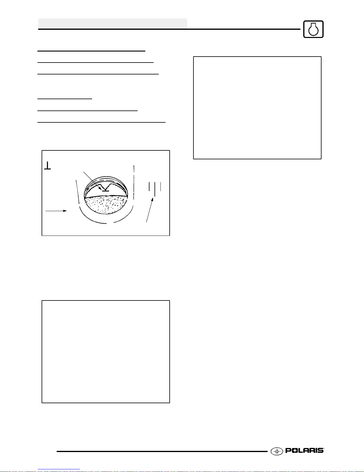
ENGINE
ENGINE DISASSEMBLY
REFER TO PAGE 3.7 FOR ENGINE
REMOVAL / INSTALLATION NOTES.
CAM CHAIN
TENSIONER/ROCKER
ARM/CAMSHAFT REMOV
1. Removeignitiontiming inspectionplug from recoil
housing.
TDC “T” Mark
Rotation
AL
should have clearance at this point.
5. Remove cam chain tensioner plug, sealing
washer, and spring. CAUTION: The plug is
under spring tension. Maintain inward pressure
while removing.
6. Remove the two 6x25 mm cam chain tensioner
flange bolts.
7. Tap lightly on tensioner body with a soft face
hammer and remove tensioner.
Advance Marks
To position crankshaft at Top Dead Center (TDC)
on compression stroke:
2. Rotate engine slowly in the direction of rotation
watching intake valves open and start to close.
3. Continue to rotate engine slowly, watching
camshaft sprocket marks and the mark in the
timing inspection hole.
4. Align single (TDC) mark on flywheel with
projection in inspection hole, and the cam
sprocket pin (facing upward) aligned with the
camshaft to crankshaft center line. NOTE: The
cam lobe should be pointing down and valves
3.14
Page 65

ENGINE
CAM CHAIN TENSIONER
INSPECTION
B
A
1. Pull cam chain tensioner plunger outward to the
end of its travel. Inspectteeth onratchet pawl(A)
and plunger teeth (B) for wear or damage.
2. Pushratchet pawl andholdit. Theplunger should
move smoothly in and out of the tensioner body.
3. Releaseratchetpawl andpushinward onplunger.
It should remain locked in position and not move
inward.
ROCKER ARM/SHAFT
INSPECTION
1. Mark or tag rocker arms to keep them in order for
assembly.
2. Inspect each rocker arm cam follower surface. If
there is any damage or uneven wear, replace the
rocker arm. NOTE: Always inspect camshaft
lobe if rocker arms are worn or damaged.
Tensioner Spring Free Length:
2.02I (5.13 cm)
4. Measurefree length of tensioner spring. Replace
spring if excessively worn. Compare to
specifications.
5. Replace entire tensioner assembly if any part is
worn or damaged.
3. Measure O.D. of rocker shaft. Inspect it for wear
or damage. Compare to specifications.
Rocker Shaft O.D.:
.8656-.8661I (21.987-22.0 mm)
3.15
Page 66
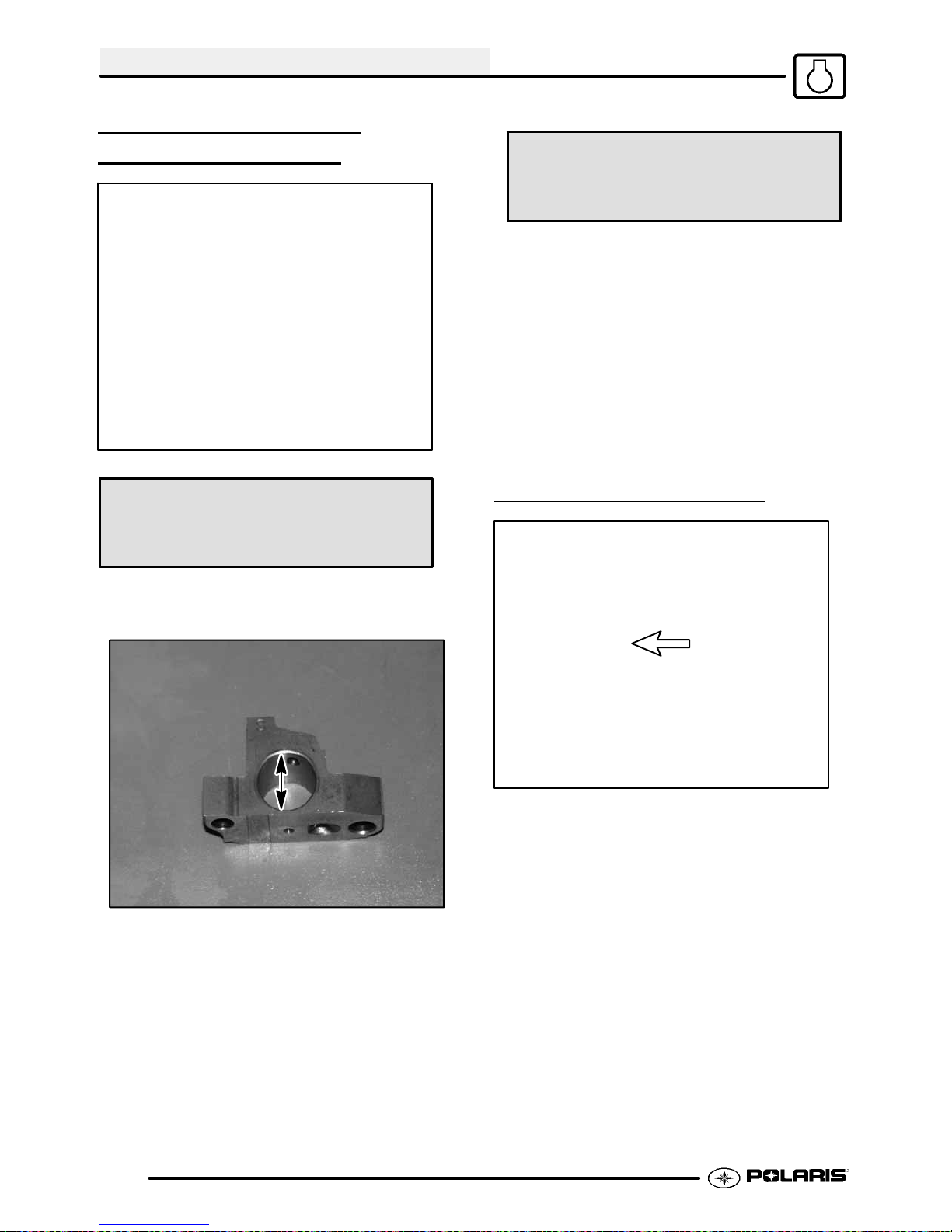
ENGINE
ROCKER ARM/SHAFT
INSPECTION, CONT
Rocker Arm & Support I.D.:
.8669-.8678I (22.020-22.041 mm)
4. Measure I.D. of each rocker arm and compare to
specifications.
.
Rocker Shaft Oil Clearance:
Std: .0008-.0021I (.020-.054 mm)
Limit: .0039I (.10 mm)
5. Measure I.D. of both rocker arm shaft supports
and visually inspect surface. Compare to
specifications.
6. Subtract rocker shaft O.D. from rocker arm &
shaft support I.D. This is the oil clearance.
Compare to specifications.
7. Inspectrocker adjuster screwsforwear,pitting,or
damage to threads of the adjuster or locknut.
Replace all worn or damaged parts. NOTE: The
end of the adjuster screwis hardened and cannot
be ground or re-faced.
CAMSHAFT REMOVAL
3.16
1. Remove thermostat housing.
2. Remove camshaft sprocket inspection cover.
Page 67
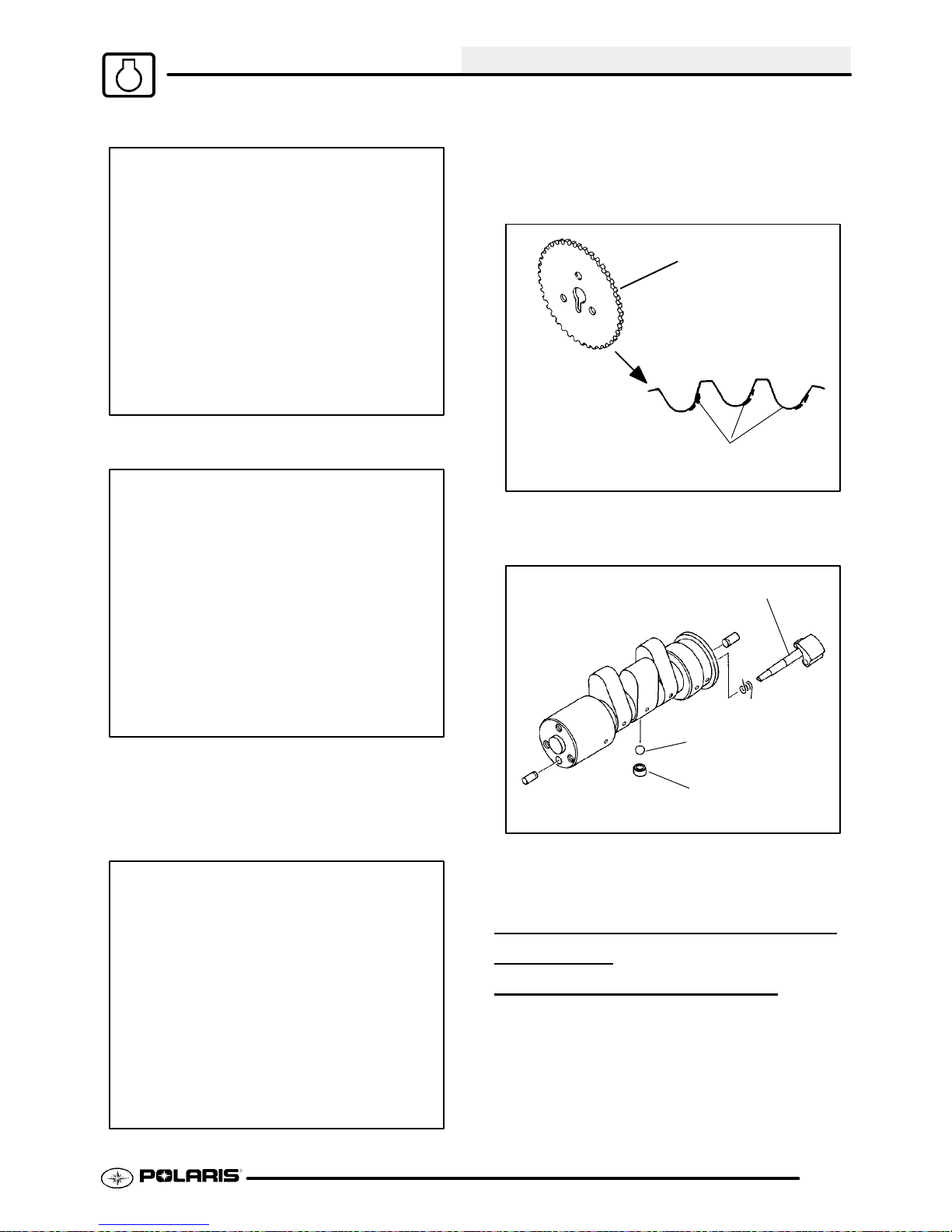
ENGINE
3. Loosen three camshaft sprocket bolts.
4. Remove camshaft end cap and O-Ring.
7. Slide camshaft inward to allow removal of cam
sprocketandremovesprocketfrom camshaftand
chain.
8. Secure cam chain with a wire to prevent it from
falling into the crankcase.
Sprocket Teeth
Inspect for Areas of Tooth
Wear or Damage
9. Inspect cam sprocket teeth for wear or damage.
Replace if necessary.
5. Inspect camshaft end cap (thrust face) for wear.
Replace if worn or damaged.
6. Place a clean shop towel in the area below cam
chain sprocket and remove sprocket retaining
bolts.
Decompressor Shaft
Decompressor Ball
Retainer Sleeve
10. Slide camshaft out the PTO side of the cylinder
head.
AUTOMATIC COMPRESSION
RELEASE
REMOV
NOTE: The automatic compression release
mechanism can be inspected and serviced without
removing the camshaft from the cylinder head. The
actuator ball in the camshaft is not replaceable.
Replace the camshaft as an assembly if the actuator
ball is worn or damaged.
AL/INSPECTION
3.17
Page 68

ENGINE
C
A
B
1. Check release lever shaft (A) for smooth
operation throughout the entire range of rotation.
The spring (B) should hold the shaft weight
against the stop pin. In this position, the actuator
ball (C) will be held outward in the compression
release mode.
2. Remove release lever shaft and return spring.
3. Inspect shaft for wear or galling.
4. Inspect lobe on end of release lever shaft and
actuator ball for wear and replace if necessary.
If Camshaft Is Removed From Engine:
3. Turn the camshaft until the actuator ball is in the
lowest position and install the release lever shaft.
If Camshaft Is Installed In The Engine:
4. Use a small magnet to draw the actuator ball
outward, or rotate the engine until the cam lobes
face upward and install release lever shaft.
5. Position camshaft as shown at bottom of
illustration at right.
6. Place arm of spring under stop pin as shown and
push release lever inward until fully seated. Do
not pre-wind the spring one full turn or the
compression release will not disengage when the
engine starts. Check operation of mechanism as
outlined in Step 1 of Removal (above).
NOTE: Whenshaft is properly installed,actuator
ballwill beheld inthe “out” position. It is important
to note that spring pressure is very light.
CAMSHAFT INSPECTION
1. Visually inspect each cam lobe for wear, chafing
or damage.
2. Thoroughly clean the cam shaft, making sure
the oil feed holes are not obstructed.
AUTOMATIC COMPRESSION
RELEASE INSTALLA
1. Slide spring onto shaft.
2. Apply engine oil to release lever shaft.
The actuator ball must be held outward to allow
installation of the release lever shaft.
Stop pin
Spring in relaxed position
TION
Lubrication holes
Lobe height
Cam Lobe Height (Intake & Exhaust):
Std: 1.2884-1.2924I (32.726-32.826 mm)
Limit: 1.2766I (32.426 mm)
3.18
Page 69

ENGINE
3. Measure height of each cam lobe using a
micrometer. Compare to specifications.
Journal O.D.
Journal
Camshaft Journal O.D.:
Mag & PTO End: 1.4935-1.4941I
(37.935-37.950 mm)
4. Measure camshaft journal outside diameter
(O.D.)
5. Measure ID of camshaft journal bore.
Camshaft Journal I.D.:
Mag & PTO End: 1.4963-1.4970I
(38.005-38.025 mm)
CYLINDER HEAD REMOVAL
1. Remove the two 6mm flange bolts (A) from
cylinder head. See next exploded view on next
page to view item A.
2. Loosen each of the four cylinder head bolts
evenly 1/8 turn each time in a criss-cross pattern
until loose.
B
3. Remove bolts (B) and tap cylinder head lightly
with a plastic hammer until loose. CAUTION:
Tap only in reinforced areas or on thick parts of
cylinder head casting to avoid damaging the
thread.
4. Remove cylinder head and head gasket.
Calculate oil clearance by subtracting journal OD
from journal bore ID. Compare to specifications.
Camshaft Oil Clearance:
Std: .0022-.0035I (.055-.090 mm)
Limit: .0039I (.10 mm)
NOTE: Replace camshaft if damaged or if any part
is worn past the service limit.
NOTE: Replace cylinder head if camshaft journal
bore is damaged or worn excessively.
3.19
Page 70

ENGINE
CYLINDER HEAD EXPLODED VIEW, EH50PL
EH50PL
3.20
Page 71

ENGINE
CYLINDER HEAD
INSPECTION
(A)
1. Thoroughly clean cylinder head (A) surface to
remove all traces of gasket material and carbon.
CAUTION: Use care not to damage sealing
surface.
CYLINDER HEAD WARPAGE
CYLINDER HEAD
DISASSEMBL
WARNING: Wear eye protection or a face shield
during cylinder head disassembly and reassembly.
NOTE: Keep all parts in order with respect to their
location in the cylinder head.
1. Using a valve spring compressor (A), compress
the valve spring and remove the split keeper.
NOTE: To prevent loss of tension, do not
compress the valve springmore than necessary.
Y
A
Cylinder Head Warpage Limit:
.002″ (.05 mm)
1. Lay a straight edge across the surface of the
cylinder head at several different points and
measure warpage by inserting a feeler gauge
between the straight edge and the cylinder head
surface. If warpage exceeds the service limit,
replace the cylinder head.
A
2. Remove spring retainer and spring.
NOTE: The valve springs should be positioned with
the tightly wound coils against the cylinder head on
progressively wound springs (A).
3. Pushvalve out, keeping it inorder forreassembly
in the same guide.
4. Measure free length of spring with a Vernier
caliper. Check spring for squareness. Compare
3.21
Page 72
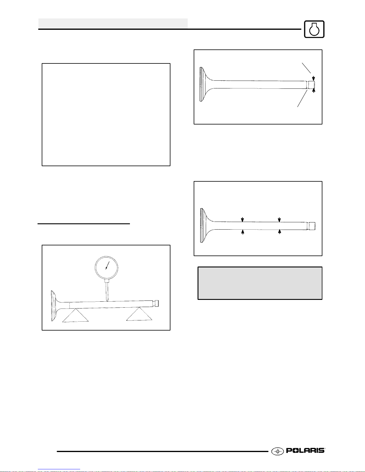
ENGINE
to specifications. Replace spring if either
measurement is out of specification
5. Remove valve seals. CAUTION: Replace seals
whenever the cylinder head is disassembled.
Hardened, cracked or worn valve seals will cause
excessive oil consumption and carbon buildup.
indicator.
A
B
3. Check end of valve stem for flaring, pitting, wear
or damage (A).
4. Inspect split keeper groove for wear or flaring of
the keeper seat area (B). NOTE: The valves
cannot be re-faced or end ground. They must be
replaced if worn, bent, or damaged.
Measure valve stem in
several places.
VALVE INSPECTION
1. Remove all carbon from valve with a soft wire
wheel.
2. Check valve face for runout, pitting, and burnt
spots. To check for bent valve stems, mount
valve in a drill or use “V” blocks and a dial
Valve Stem Diameter:
Intake: .2343-.2348I (5.950-5.965 mm)
Exhaust: .2341-.2346I (5.945-5.960 mm)
5. Measure diameter of valve stem with a
micrometer in three places and in two different
directions (six measurements total). Compareto
specifications.
3.22
Page 73

Valve Guide I.D.:
.2362-.2367I (6.0-6.012 mm)
ENGINE
VALVE SEAT SERVICE
Valve Seat Inspection
Inspect valve seat in cylinder head for pitting, burnt
spots, roughness, and uneven surface. If any of the
above conditions exist, the valve seat must be
reconditioned. See Valve Seat Reconditioning, Page
3.25. If the valve seat is cracked the cylinder head
must be replaced.
Cylinder Head Reconditioning
NOTE: Servicing the valve guides and valve seats
requires special tools and a thorough knowledge of
reconditioning techniques. Follow the instructions
provided in the cylinder head service tool kit.
CAUTION: Wear eye protection when performing
cylinder head service. Valve guide replacement will
require heating of the cylinder head. Wear gloves to
prevent burns.
6. Measure valve guide inside diameter at the top
middle and end of the guide using a small hole
gauge and a micrometer. Measure in two
directions, front to back and side to side.
7. Subtract valvestem measurement to obtainstem
to guide clearance. NOTE: Be sure to measure
each guide and valve combination individually.
8. Replace valve and/or guide if clearance is
excessive. Compare to specifications.
NOTE: If valve guides are replaced, valve seats
must be reconditioned. Refer to Valve Seat
Reconditioning for procedure.
COMBUSTION CHAMBER
Valve Guide Removal/Installation
1. Removeall carbon deposits from the combustion
chamber, valve seat and valve guide area before
attempting to remove valve guides. CAUTION:
Carbon deposits are extremely abrasiveand may
damage the valve guide bore when guides are
removed.
2. Placenew valve guides in a freezer forat least15
minutes while heating cylinder head.
3. Heatcylinder head in an ovenor use a hot plateto
bring cylinder head temperature to 212° F (100°
C). CAUTION: Do not use a torch to heat
cylinder head or warpage mayresultfromuneven
heating. Head temperature can be checked with
a pyrometer or a welding temperature stick.
VALVE SEAT
RECONDITIONING
Follow the manufacturers instructions provided with
the valve seat cutters in the Valve Seat
Reconditioning Kit (PN 2200634). Abrasive stone
seat reconditioning equipment can also be used.
Keep all valves in order with their respective seat.
Clean all accumulated carbon deposits from
combustion chamber and valve seat area with a soft
wire brush.
3.23
Page 74

ENGINE
Reaming The Valve Guide
Too
Wide
NOTE: Valveseat width and point of contact on the
valve face is very important for proper sealing. The
valve must contact the valve seat over the entire
circumference of the seat, and the seat must be the
properwidth all the way around. If theseat isuneven,
compression leakage will result. If the seat is too
wide, seat pressure is reduced, causing carbon
accumulation and possible compression loss. If the
seat is too narrow, heat transfer from valve to seat is
reduced and the valve may overheat and warp,
resulting in burnt valves.
1. When thoroughly heated, place cylinder head on
blocks of wood which will allow the old guides to
be removed.
2. Using valve guide driver, drive guides out of the
cylinder head from the combustionchamber side.
Becarefulnot to damage guidebore or valve seat
when removing guides.
3. Place cylinder head on cylinder head table.
NOTE: Be sure cylinder head is still at 212° F
(100° C) before installing new guides.
Uneven
Good
Too
Narrow
5. Allow cylinder head to cool to room temperature.
Apply cutting oil to the reamer. Guides should be
reamed from the valve spring side of the cylinder
head. Ream each guide to size by turning the
reamer clockwise continually. Continue to rotate
reamer clockwise during removal of the tool.
6. Cleanguides thoroughly withhot soapywaterand
a nylon brush. Rinse and dry with compressed
air. Apply clean engine oil to guides.
7. Install pilot into valve guide.
8. Apply cutting oil to valve seat and cutter.
A
Valve Guide Installed Height
Valve Guide Height:
.689-.709I (17.5-18.0 mm)
4. Place a new guide in the valve guide installation
tool and press guide in to proper depth. Check
heightof each guide above the cylinder head (A).
NOTE: Theguidecanalsobedrivenintothe
properdepth. Inspect the guideclosely for cracks
or damage if a driver is used.
3.24
9. Place 46° cutter on the pilot and make a light cut.
10. Inspect the cut area of the seat.
S If thecontact area is less than75% of the
circumferenceof the seat, rotate the pilot
180° and make another light cut.
S If the cutter now contacts the uncut
portion of the seat, check the pilot. Look
for burrs, nicks, or runout. If the pilot is
bent it must be replaced.
Page 75

S If the contact area of the cutter is in the
same place, the valve guide is distorted
from improper installation and must be
replaced. Be sure the cylinder head is at
the proper temperature and replace the
guide.
S If the contact area of the initial cut is
greater than 75%, continue to cut the
seat until all pits are removed and a new
seat surface is evident. NOTE: Remove
only the amount of material
necessary to repair the seat surface.
(A)
ENGINE
Valve Seat Width:
Intake Std: .028I (.7 mm)
Limit: .055I (1.4 mm)
Exhaust Std: .039I (1.0 mm)
Limit: .071I (1.8 mm)
Seat
Width
1 1. Tocheck the contact area of the seat on the valve
face,apply athin coatingof PrussianBluetpaste
to the valve seat. If using an interference angle
(46°) apply black permanent marker to the entire
valveface(A).
12. Insert valve into guide and tap valve lightly into
place a few times.
13. Remove valve and check where the Prussian
Bluet indicates seat contact on the valve face.
The valve seat should contact the middle of the
valve face or slightly above, and must be the
proper width.
S If the indicated seat contact is at the
top edge of the valve face and
contacts the margin area(B) it is too
high on the valve face. Use the 30°
cutter to lower the valve seat.
S If too low use the 60° or 75° cutterto
raise the seat. When contact area is
centered on thevalve face, measure
seat width.
S If the seat is too wide or uneven, use
both top and bottom cutters to
narrow the seat.
S If the seat is too narrow, widen using
the 45° cutter and re-check contact
pointonthevalveface andseatwidth
after each cut.
Bottom - 60° or 75°
NOTE: When using an interference angle, the seat
contact point on the valve will be very narrow, and is
a normal condition. Look for an even and continuous
contact point on the black marker, all the way around
the valve face.
14. Clean all filings from the area with hot soapy
water, rinse, and dry with compressed air.
15. Lubricate the valve guides with clean engine oil,
andapply oil or water based lapping compound to
the face of the valve. Lappingisnot requiredwith
an interference angle.
16. Insert the valve into its respective guide and lap
using a lapping tool or a section of fuel line
connected to the valve stem.
17. Rotate the valve rapidly back and forth until the
cutsounds smooth. Lift thevalve slightly offof the
seat, rotate 1/4 turn, and repeat the lapping
process. Dothis fourto fivetimesuntil the valveis
fully seated, and repeat process for the other
valve(s).
Seat - 45° or 46°
Top - 30°
3.25
Page 76
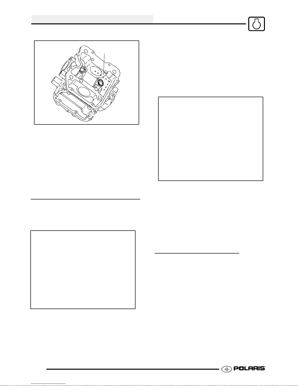
ENGINE
A
18. Clean cylinder head, valves, and camshaft oil
supply passage (A) thoroughly.
19. If oil passage blind plug was removed, apply
Crankcase Sealant (PN 2871557) or equivalent
sealer to the threads and install, torquing to 8 ft.
lbs. (11 Nm). CAUTION: Donot allow sealant to
enter oil passage.
20. Spray electrical contact cleaner into oil passage
and dry using compressed air.
CYLINDER HEAD ASSEMBLY
CAUTION: Wear eye protection during assembly.
NOTE: Assemble the valves one at a time to
maintain proper order.
1. Install new valve seals on valve guides.
2. Apply engine oil to valve guides and seats.
3. Coat valve stem with molybdenum disulfide
grease.
4. Install valve carefully with a rotating motion to
avoid damaging valve seal.
5. Dip valve spring and retainer in clean engine oil
andinstall spring with closely spaced coils toward
the cylinder head.
6. Place retainer on spring and install valve spring
compressor. Compress spring only enough to
allow split keeper installation to prevent loss of
spring tension. Install split keepers with the gap
even on both sides.
7. Repeat procedure for remaining valve.
8. When all valves are installed, tap lightly with soft
faced hammeron the endof the valvestoseat the
split keepers.
3.26
VALVE SEALING TEST
1. Clean and dry the combustion chamber area.
2. Pour a small amount of clean, high flash point
solvent intothe intake port and check for leakage
aroundeachintakevalve. The valveseatsshould
hold fluid with no seepage.
3. Repeat for exhaust valves by pouring fluid into
exhaust port.
Page 77

ENGINE
EXHAUST VALVE
CLEARANCE
Feeler Gauge for Both Valves
NOTE: The exhaust valves share a common rocker
arm, and must be adjusted using two feeler gauges.
1. Insert .006 feeler gauge(s) between end of
exhaust valve stem and adjuster screw(s).
2. Loosenlocknut(s)and turn adjuster screw(s) until
there is a slight drag on feeler gauge(s). The
Valve/Clutch Adjuster Tool (PA--44689) can be
used to adjust the 500 engine valves. NOTE:
Both feelergauges shouldremain insertedduring
adjustment of each valve.
ADJUSTMENT
500 Engine
CYLINDER/PISTON REMOVAL
AND
NOTE: Follow engine disassembly procedures to
remove valve cover, camshaft and rocker arms, and
cylinder head.
1. Remove cam chain guide at front of cylinder.
INSPECTION
EXHAUST VALVE CLEARANCE
.006″ (.15 mm)
3. When clearance is correct, hold adjuster screw
and tighten locknut securely
4. Re-check the valve clearance.
5. Repeat adjustment procedure if necessary until
clearance is correct with locknut secured.
2. Loosen all four oil pipe banjo bolts and then
remove the bolts and eight sealing washers.
Remove the pipes.
3.27
Page 78

ENGINE
3. Loosen hose clamps and remove coolant inlet
hose.
4. Remove the two 6 mm cylinder base bolts.
5. Loosen each of the four large cylinder base bolts
1/4 turn at a time in a criss-cross pattern until
loose and remove bolts.
NOTE: The bolts are inside the water jacket.
PISTON REMOVAL
1. Remove circlip. Note piston directional arrow
pointing toward the right (Mag) side of engine.
2. Remove piston circlip and push piston pin out of
piston. If necessary, heat the crown of the piston
slightly with a propane torch. CAUTION: Do not
apply heat to the piston rings. The ring may lose
radial tension.
6. Tap cylinder lightly with a plastic hammer in the
reinforced areas only until loose.
7. Rock cylinder forward and backward and lift it
from the crankcase, supporting piston and
connecting rod. Support piston with Piston
Support Block (PN 2870390).
8. Remove dowel pins from crankcase.
3.28
Page 79

3. Remove top compression ring.
*Using a piston ring pliers: Carefully expand ring
andlift it off the piston. CAUTION: Do notexpandthe
ring more than the amount necessary to remove it
from the piston, or the ring may break.
*Byhand: Placingboththumbsasshown, spread the
ring open and push up on the opposite side. Do not
scratch the ring lands.
ENGINE
2. Inspectthetop of the cylinder for warpageusing a
straight edge and feeler gauge.
Cylinder Warpage:
.002″ (.05 mm)
3. Inspect cylinder for wear, scratches, or damage.
A
4. Repeat procedure for second ring.
The oil control ring is a three piece design consisting
of a top and bottom steel rail and a center expander
section. The top rail has a locating tab on the end
which fits into a notch (A) in the upper oil ring land of
the piston.
5. Remove the top rail first followed by the bottom
rail.
6. Remove the expander.
CYLINDER INSPECTION
1. Remove all gasket material from the cylinder
sealing surfaces.
1/2″ Down From Top of Cylinder
X
X
X
1/2″ Up From Bottom
4. Inspect cylinder for taper and out of round with a
telescoping gaugeor a dial bore gauge. Measure
intwodifferentdirections,front toback andside to
side, on three different levels (1/2″ down from top,
in the middle, and 1/2″ up from bottom).
5. Record measurements. If cylinder is tapered or
out of round beyond .002, the cylinder must be
re-bored oversize, or replaced.
Y
Y
Y
Cylinder Taper
Limit: .002 Max.
Cylinder Out of Round
Limit: .002 Max.
Standard Bore Size:
3.6221-3.6228I (92.00-92.012mm)
3.29
Page 80

ENGINE
PISTON-TO-CYLINDER
CLEARANCE
Piston
40 mm
Piston Pin
1. Measurepistonoutsidediameter atapoint 40mm
down from the top of the piston at a right angle to
the directionof the pistonpin.
2. Subtract this measurement from the maximum
cylinder measurement obtained in Step 5 above.
Piston to Cylinder Clearance
1. Measure piston pin bore.
Piston Pin Measurement Locations
Piston Pin O.D.
.9053-.9055I (22.994-23.0 mm)
2. Measure piston pin O.D. Replace piston and/or
piston pin if out of tolerance.
Std: .0006-.0018I (.015-.045 mm)
Piston O.D.:
Std: 3.6204-3.6215I (91.970-91.985 mm)
PISTON/ROD INSPECTION
Piston Pin Bore
Piston Pin Bore:
.9055-.9057I (23.0-23.006 mm)
3. Measure connecting rod small end ID.
Piston
Ring
Feeler Gauge
Piston Ring-to-Groove Clearance
Top Ring Std: .0016-.0031I (.040-.080 mm)
Limit: .0059I (15 mm)
Second Ring Std: .0012-.0028I (.030-.070 mm)
Limit: .0059I (15 mm)
3.30
4. Measure piston ring to groove clearance by
placing the ring in the ring land and measuring
with athickness gauge. Replacepiston andrings
if ring-to-groove clearance exceeds service
limits.
Page 81
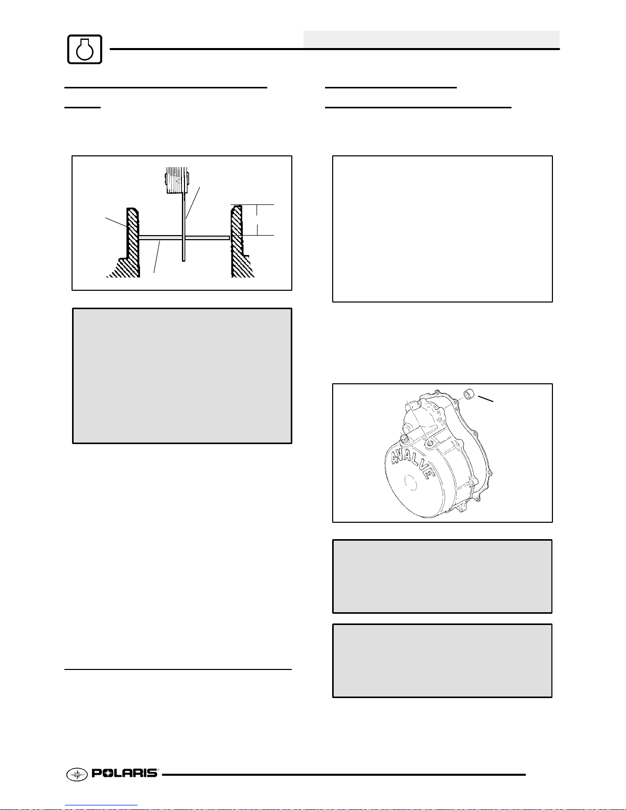
ENGINE
PISTON RING INSTALLED
GAP
1. Placeeach pistonring insidecylinderusing piston
to push ring squarely into placeas shown at right.
Feeler Gauge
Cylinder
Piston Ring
Piston Ring Installed Gap
Top Ring
Std: .0079-.0138I (.20-.36 mm)
Limit: .039I (1.0 mm)
Second Ring
Std: .0079-.0138I (.20-.36 mm)
Limit: .039I (1.0 mm)
Oil Ring
Std: .0079-.0276I (.20-.70 mm)
Limit: .059I (1.5 mm)
25-50mm
STARTER DRIVE
REMOV
1. Remove recoil housing bolts and remove
housing.
2. Remove starter drive assembly. Note the thrust
washer located at the rear of the drive
mechanism.
3. Inspectthethrustwasher for wearor damageand
replace if necessary.
AL/INSPECTION
A
2. Measureinstalled gap with a feeler gauge at both
the top and bottom of the cylinder. NOTE: A
difference in end gap indicates cylinder taper.
The cylinder should be measured for excessive
taper and out of round.
3. If thebottominstalled gap measurement exceeds
the service limit, replace the rings. If ring gap is
below specified limit, file ring ends until gap is
within specified range.
NOTE: Always check piston ring installed gap after
re-boring a cylinder or when installing new rings. A
re-bored cylinder should always be scrubbed
thoroughly with hot soapy water , rinsed, and dried
completely. Wipe cylinder bore with an oil rag
immediately to remove residue and prevent rust.
CRANKCASE DISASSEMBLY
NOTE: The recoilstarter,startermotor,starterdrive,
flywheel, stator, cam chain and sprockets can be
serviced with the engine in the frame.
Std. Bushing ID:
.4735″-.4740″ (11.11-12.04 mm)
Std. Shaft OD:
.470″-.472″ (11.93-11.99 mm)
Starter Drive Bushing Clearance:
Std: .0015″-.004″ (.038-.102 mm)
Service Limit:
.008″ (.203 mm)
4. Measurethe OD of the starter drive shaft on both
ends and record.
3.31
Page 82

ENGINE
5. Measure the ID of the bushing in the recoil
housing (A) and in the crankcase and record.
Measure in two directions 90° apart to determine
if bushing is out of round. Calculate bushing
clearance. Replacebushingif clearanceexceeds
the service limit.
6. Inspect gear teeth on starter drive. Replace
starter drive if gear teeth are cracked, worn, or
broken.
FLYWHEEL/STATOR
REMOV
1. Remove flywheel nut and washer.
2. Install Flywheel Puller (PN 2871043) and remove
flywheel. CAUTION: Do not thread the puller
bolts into the flywheel more than 1/4″ or stator
coils may be damaged.
3. Markornote positionof stator plateoncrankcase.
4. Remove bolts and carefully remove stator
assembly,beingcareful not todamagecrankshaft
bushing on stator plate.
AL/INSPECTION
6. Remove oil passage O-Ring (B).
7. Remove large sealing O-Ring from outer edge of
stator plate.
CAM CHAIN/TENSIONER
BLADE
A
5. Replace crankshaft seal (A).
A
1. Remove bolt securing tensioner blade to
crankcase (A).
2. Remove blade and inspect for cracks, wear, or
damage.
B
B
3.32
Page 83

3. Removecam chain(B). Inspect chain for worn or
missing rollers or damage. Stretch chain tight on
a flat surface and apply a 10 lb. (4.53 kg) load.
Measure length of a 20 pitch section of chain.
Replace if worn past service limit.
Chain Service Limit:
5.407″ (13.7 cm)
4. Using the special socket, remove the crankshaft
slotted nut (A). NOTE: The slotted nut is a left
hand thread.
5. Remove cam chain drive sprocket (B) and
Woodruff key from crankshaft.
6. Inspect sprocket teeth for wear or damage.
7. Inspect Woodruff key for wear.
8. Replace any worn or damaged parts.
ONE WAY VALVE
ENGINE
One Way Valve Spring Free Length:
Std: 1.450″ (3.68 cm)
3. Inspect valve for wear.
4. Check seat area for nicks or foreign material that
may prevent proper sealing of valve.
CRANKCASE SEPARATION
Theoneway valvepreventsoilfromdrainingoutof the
oil tank and into the crankcase when the engine is off.
It must be clean and have adequate spring pressure
in order to seal properly.
CD
1. Remove cap bolt (A), sealing washer (B), spring
(C), and one way valve (D) from PTO side
crankcase.
2. Inspect free length of spring and check coils for
distortion.
B
A
1. Remove flange bolts (10) from magneto side
crankcase evenly in a criss-cross pattern.
2. Separate crankcase by tapping with a soft faced
hammer in reinforced areas.
3. Tap lightly on balancer gear with a brass drift
through the hole in the crankcase if necessary ,to
ensure the balancer shaft stays in the PTO side
crankcase. Watch the gap along the crankcase
mating surface and separate the crankcase
evenly. It may also be necessary to tap the oil
pump shaft lightly to separate the crankcase.
CAUTION: Do not strike the oil pump shaft at an
angle or the shaft may bend, causing irreparable
damage. Tap only lightly on the pump shaft if
necessary.
4. Remove the Mag (RH) crankcase from the PTO
case.
3.33
Page 84

ENGINE
OIL PUMP
REMOV
1. Remove pump shaft bearing (A) and thrust
washer (B) from pump shaft.
2. Remove (2) bolts holding pump drive gear (C).
3. Inspect drive gear teeth for cracks, damage or
excessive wear.
AL/INSPECTION
C
B
A
4. Removethree oil pumpretainingbolts andpump.
5. Inspect mating surface of crankcase and oil
pump. Check for nicks, burrs, or surface
irregularities.
6. Remove the three screws and strainer screen
from pump.
7. Clean screen thoroughly.
3.34
8. Remove pump body screw and feed chamber
cover.
Page 85

9. Measure pump end clearance using a feeler
gauge and straight edge.
Pump End Clearance:
ENGINE
5. Install inner feed rotor and feed chamber cover
with screw.
6. Tighten screw securely.
7. Install screen on pump body.
8. Installoilpump oncrankcase andtorquebolts to6
ft. lbs. (8 Nm).
Std: .001-.003 (.0254-.0762 mm)
Wear Limit: .004 (.1016 mm)
10. Measure clearance between outer feed rotor and
pump body with a feeler gauge.
Rotor Tip Clearance:
Oil Pump Attaching Bolt Torque:
6 ft. lbs. (8 Nm)
COUNTER BALANCER
SHAFT
REMOV
A
AL/INSPECTION
Std: .005 (.127 mm)
Wear Limit: .008 (.2032 mm)
1 1. Measure rotor tip clearance with a feeler gauge.
12. Remove inner and outer feed rotor and pump
chamber body.
13. Repeat measurements for scavenge rotor.
14. Remove inner and outer scavenge rotor and
inspect pump shaft for wear.
OIL PUMP ASSEMBLY
1. Clean and dry all parts thoroughly. Apply clean
engineoiltoallparts. Donot usegasketsealer on
the pump body mating surfaces or oil passages
will become plugged.
2. Install pump shaft and scavenge rotor drive pin.
3. Installouter scavenge rotor,innerscavengerotor,
and scavenge casing.
4. Install outer feed rotor and inner feed rotor drive
pin.
1. Remove the shim washer (A) from the counter
balancer shaft.
3.35
Page 86
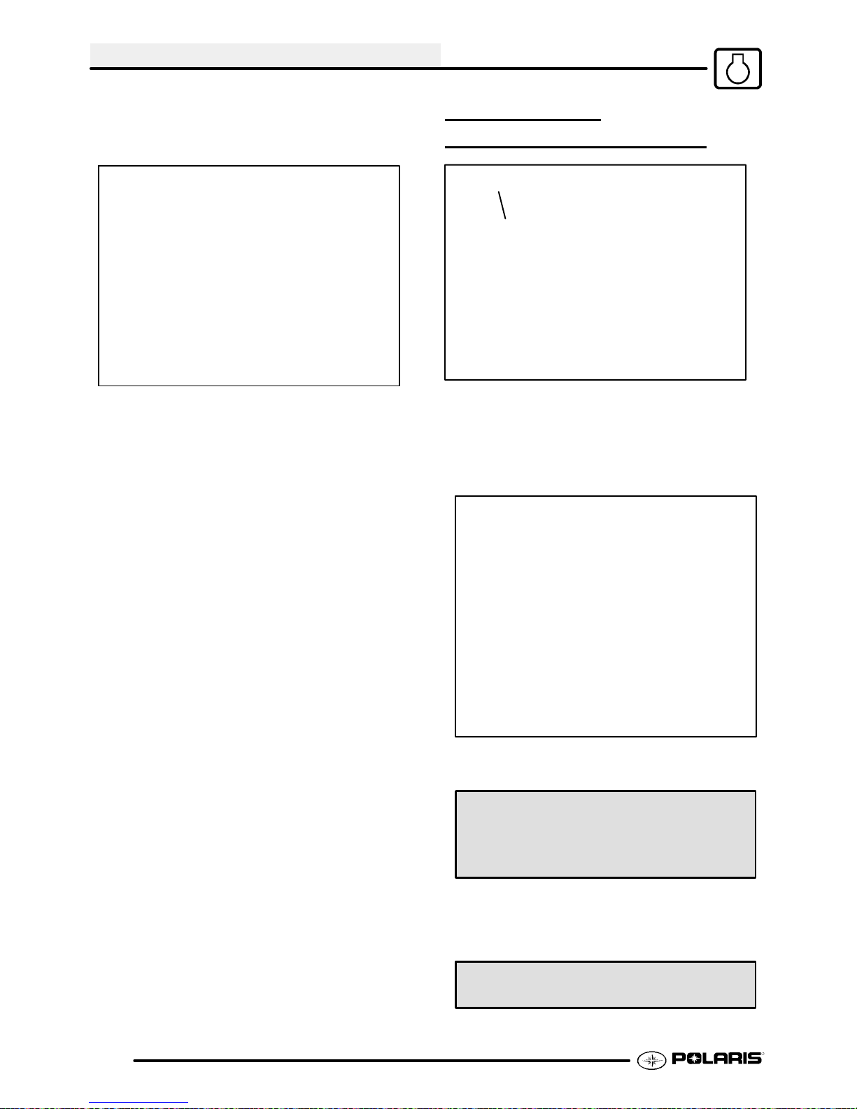
ENGINE
2. Note the alignment dots on the balancer and
crankshaft gears, the marks must be aligned
during reassembly.
3. Turnthe shaftuntilbalancercounterweightsclear
the crankshaft and remove the balancer shaft
from the crankcase.
4. Inspect the balancer drive gear and pump shaft
drive gear.
5. Replace the shaft if gear teeth are abnormally
worn or damaged.
6. Inspect the balancer shaft bearings.
NOTE: Due to extremely close tolerances and
minimal wear, the balancer shaft ball bearings must
be inspected visually and by feel. Look for signs of
discoloration, scoring or galling. Turn the inner race
of each bearing. The bearings should turn smoothly
and quietly. The outer race of each bearing should fit
tightly inthecrankcase. The inner raceshouldbefirm
withminimal sidetosidemovement andnodetectable
up and down movement.
CRANKSHAFT
REMOVAL/INSPECTION
A
1. Removetheshim washer(A) from thecrankshaft.
2. Support the PTO side crankcase and crankshaft;
press the crankshaft out. Be careful not to
damage the crankcase mating surface or
connecting rod.
3.36
3. Useafeelergauge tomeasure theconnectingrod
big end side clearance.
Connecting Rod Big End Side Clearance:
Std: .0039-.0256I (.1-.65 mm)
Limit: .0315I (.80 mm)
4. Place the crankshaft in a truing stand or V-blocks
and measure the runout on both ends with a dial
indicator.
Max Runout: .0024″ (.06 mm)
Page 87

ENGINE
5. Measure the connecting rod big end radial
clearance.
Big End Radial Clearance:
Std: .0004-.0015I (.011-.038 mm)
Limit: .0020I (.05 mm)
6. Inspect the crankshaft main bearing journals for
scoring and abnormal wear.
CRANKCASE BEARING
INSPECTION
PUMP SHAFT OIL SEAL/
WATER PUMP
SEAL
REMOV AL (ENGINE
MECHANICAL
DISASSEMBLED)
NOTE: The water pump mechanical seal can be
removedwithout removing theengine. Refer toWater
Pump Mechanical Seal Installation.
Replace the pump shaft seal and water pump
mechanical seal whenever the crankcase is
disassembled.
1. Remove the seal from the PTO side crankcase.
2. Inspect the crankshaft main bearings, balancer
shaft bearings, and pump shaft bearing.
NOTE: Due to extremely close tolerances and
minimal wear, the bearings must be inspected
visually, and by feel. Look for signs of discoloration,
scoring or galling. Turntheinner race of eachbearing.
The bearings should turn smoothly and quietly. The
outer race of each bearing should fit tightly in the
crankcase. The inner race should be firm with
minimal side to side movement and no detectable up
and down movement.
3. Support the crankcase and drive or press the
main bearings out of each crankcase.
4. To remove balancer shaft bearings and pump
shaft bearing use a blind hole bearing puller.
NOTE: Bearings are stressed during the removal
process and should not be re-used!
1. Remove the pump shaft bearing from the
Magneto (right hand) side crankcase.
2. Pry out the oil seal, noting the direction of
installation with the spring side facing IN (toward
inside of case).
3. Drive the water pump mechanical seal out of the
crankcase from insideto outside. Note: The new
mechanical seal must be installed after
crankcases are assembled, using a special tool.
See Mechanical Seal Installation.
the
CRANKCASE INSPECTION
1. Remove all traces of gasket sealer from the
crankcase mating surfaces. Inspect thesurfaces
closely for nicks, burrs or damage.
2. Check the oil pump and oil passage mating
surfaces to be sure they are clean and not
damaged.
3.37
Page 88

ENGINE
BEARING INSTALLATION
NOTE: To ease bearing installation, warm the
crankcase until hot to the touch. Place the bearings in
a freezer.
1. Install the bearings so the numbers are visible.
2. Drive or press new bearings into the crankcases,
usingtheproperdriver. CAUTION: Pressonly on
outer race of bearing to prevent bearing damage.
S 70 mm (2.755″) driver- For
crankshaft main bearings.
S 46mm (1.810″) For counterbalancer
bearings.
S 28 mm (1.100″) For pump shaft
bearing.
END PLAY
INSPECTION/ADJUSTMENT
2. Measure the distance from the PTO crankcase
mating surface to the main bearing using a dial
caliper and a straight edge.
Before reassembling the crankcase,the following
steps should be performed to determine the amount
ofcrankshaft, counter balancer shaft, and pumpshaft
endplay. Excessive endplaymay causeengine noise
at idle and slow speeds. T oo little play will side load
the bearings which may lead to premature bearing
failure.
CRANKSHAFT END PLAY
ADJUSTMENT
3. Subtract the thickness of the straightedge from
the measurement obtained in Step 2 and record.
PTO Case Depth
1. Make sure all bearings are firmly seated in the
both Mag and PTO crankcase.
3.38
Page 89

ENGINE
4. Measure the distance from the Magneto
crankcase mating surface to the main bearing
using the same method and record.
5. Subtract the thickness of the straightedge from
the measurement obtained in Step 4 and record.
Mag Case Depth
7. Measure the width of the crankshaft at the
bearing seats with a micrometer or dial caliper
and record.
Crankshaft Width
8. Subtract the Crankshaft Width measured in Step
7 from the Total Case Width recorded in Step 6,
and record below.
Total End Play
9. Subtract the thickness of the existing shim from
theresultof Step8 to determine if a different shim
is required. The result must be within the
specified range listed at right.
Crankshaft End Play:
.008″-.016″ (.02-.04 cm)
6. Add the readings recorded in Step 3 and Step 5
and record below.
Total Case Width
3.39
Page 90

ENGINE
COUNTER BALANCER
SHAFT END PLAY ADJUST
Step 2
1. Make sure all bearings are firmly seated in the
crankcase.
2. Measure the width of the counter balancer shaft
at the bearing seats with a dial caliper or
micrometer, and record reading.
.
Counter Balancer Shaft End Play:
.008″-.016″ (.02-.04 cm)
OIL PUMP SHAFT END PLAY
ADJUSTMENT
1. Makesurethe pumpshaftbearingisfirmlyseated
in the Magneto side crankcase.
Step3/4
3. Measure the distance from the Mag crankcase
mating surface tothe balance shaft bearingusing
a dial caliper and a straight edge. Subtract the
thickness of the straightedge and record.
4. Measure the distance from the PTO crankcase
mating surface to the bearing using the same
method outlined in Step 1, 2, and-3.
5. Add the readings obtained in Step 3 and Step 4.
6. Subtract the counter balancer shaft width
measured in Step 2 from the figure obtained in Step
5.
7. Subtract the thickness of the existing shim from
theresultof Step6 to determine if a different shim
isneeded. Theresultmustbe withinthespecified
range listed at below.
2. Measure the distance from the magneto
crankcase mating surface to the bearing using a
dial caliper and a straight edge. Subtract the
thickness of the straightedge and record.
3. Install the gear on the oil pump and measure the
width of the pump and gear. Subtract this
measurement from the measurement recordedin
Step 2.
4. Subtract the thickness of the existing shim from
theresultof Step3 to determine if a different shim
is needed. See Shaft End Play Spec. next page.
3.40
Page 91

Pump Shaft End Play:
.008″-.016″ (.02-.04 cm)
PUMP SHAFT OIL SEAL
INSTALLA
TION
ENGINE
difficult, installtwonuts onthe endof thethreaded
rod and tighten against each other.
3. Install the proper shim on the magneto end of the
crankshaft.
4. Place the balancer shaft in the PTO crankcase
aligning the timing marks on the crankshaft and
balancergears.Install the propershim washeron
the shaft.
5. Inspect the oil pump sealing surface on the
crankcase. Apply a light film of engine oil to the
surface and install the oil pump.
NOTE: Do notuse gasketsealer onthe pumpmating
surfaces.
NOTE: After engine is assembled and machine is
readiedfor field operation, oil pump MUST be primed.
Follow oil pump priming procedure on Page 3.10.
Oil Pump Bolt Torque:
6. ft. lbs. (8 Nm)
1. Install the seal from the outside of the crankcase
(water pump side) with the spring facing inward,
toward the pump shaft bearing.
2. Drive or press the seal into place using a 25 mm
(.985″) seal driver, until flush with the outer edge
of the seal bore.
3. Lubricate the seal lip with grease.
CRANKSHAFT/COUNTER
BALANCE/OIL
INSTALLA
Lubricate all bearings with clean engine oil before
assembly.
Use the Crankshaft/Water Pump Installation Kit (PN
2871283) to prevent damage to the crankshaft and
main bearings during installation.
1. Install the crankshaft into the PTO side
crankcase. Screw the threaded rod into the
crankshaft until the threads are engaged a
minimum of one inch (25.4mm).
2. Install the collar, washer, and nut onto the
threaded rod. Hold thecrankshaft and tightenthe
nut to draw the crankshaft into the main bearings
until fully seated. Loosen the nut and remove the
threaded rod from the crankshaft. If removal is
TION
PUMP
6. Alignthe drive gear with the drive pinon the pump
shaft and install the gear. Besure the gear is fully
seated and properly engaged.
7. Install the proper shimwasher onthe pump shaft.
CRANKCASE ASSEMBLY
1. Apply Crankcase Sealant (PN 2871557)tothe
crankcase mating surfaces. Be sure the
alignment pins are in place.
2. Set the crankcase in position carefully to avoid
damaging the pump shaft seal, and install the
magneto end crankshaft installation tool (follow
instructions provided with the Crankshaft/Water
Pump Installation Kit (PN 2871283).Drawthe
crankcase halves together by tightening the nut
on the tool and tapping lightly in the pump shaft
area with a soft faced hammer to maintain
alignment. Continually check alignment of the
cases during installation, closing the gap equally
until the surfaces are tightly seated.
3. Remove the tool.
3.41
Page 92
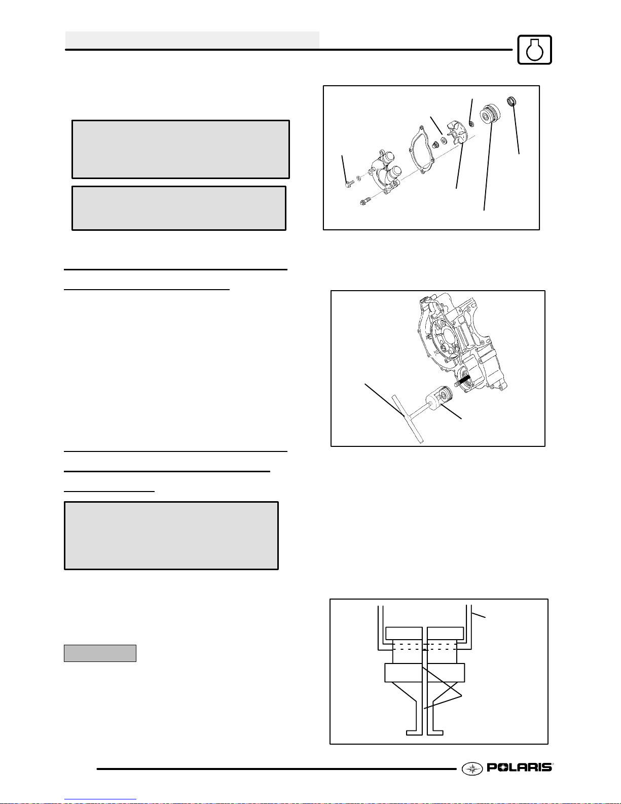
ENGINE
4. Install the crankcase flange bolts and tighten in 3
steps following the pattern on Page 3.2 to
specified torque.
Sealing Washer
(Copper or Aluminum)
Sealing Washer
Crankcase Bolt Torque:
14 ft. lb s. (19 Nm)
Crankcase Sealant:
(PN 2871557)
WATER PUMP MECHANICAL
SEAL INSTALLATION
1. Clean the seal cavity to remove all traces of old
sealer.
2. Place a new mechanical seal in the seal drive
collar, and install on the pump shaft.
3. Screw the guide onto the end of the pump shaft.
4. Installthewasherandnut andtightento drawseal
into place until fully seated.
5. Remove the guide adaptor using the additional
nut as a jam nut if necessary.
WATER PUMP MECHANICAL
SEAL REMOVAL -
ENGINE
INSTALLED
Water Pump Mechanical Seal
Puller: (PN 2872105)
Coolant Drain
Bolt
Impeller
Ill. 1
1. After the coolant has been drained, remove the
water pump cover, impeller and the sealing
washer. (Ill. 1)
T-Handle
Ill. 2
2. Slide the main puller body over the outer portion
of the mechanical seal as shown in Ill. 2 and turn
T-Handle clockwise until it contacts water pump
shaft. Continue rotating until outer portion of
mechanical seal is separated from the metal seal
body.
Mechanical Seal
Main Puller Body
Oil
Seal
Replacement T--Handle:
(PN 2872106)
This tool allows a technician to replace the
mechanical water pump seal on EH50PL engines
without removing the engine and splitting the cases.
CAUTION:
Improper or careless useof this tool or procedure can
result in a bent water pump shaft. Pump shaft
replacement requires engine removal and crankcase
separation. Use caution while performing this
procedure. Make sure that the puller is parallel to the
shaft at alltimes. Do not placesideloads onthewater
pump shaft or strike the puller or shaft in any way.
3.42
3. Insert the puller legs between the water pump
drive shaft and the remaining portion of the
mechanical seal. Attach the puller legs to the
main puller body. Ill. 3
Main puller
body
Position the split
90° to opening
on main puller
Ill. 4
body
Page 93

ENGINE
4. Ensure that the split between the puller legs is
fully supported by the main body of the tool (Ill 4).
Hex Socket Screws
Puller Legs
Lip must grasp inside
of mechanical seal.
Ill. 5
5. Tighten the hex socket screws on the puller legs
sufficiently so the lip of the puller legs will grasp
the mechanical seal. Ill. 5
ONE WAY VALVE
INSTALLA
Install the one way valve plunger, spring, and plug
using a new sealing washer.
One Way Valve Plug Torque:
16 ft. lb s. (22 Nm)
TION
CAM CHAIN DRIVE
SPROCKET INST ALLA
B
A
TION
Ill. 6
6. Turn the puller T-Handle clockwise until it
contacts thewaterpump shaft. Continuerotating
untiltheremaining portion of mechanical seal has
been removed from the cases. Ill. 6 Pump shaft
oil seal can also be replaced at this time if
necessary.
7. The Water Pump Install Kit (PN 5131135)is
required to install the new mechanical seal. This
tool is available separately and it is also included
in the Crankshaft/Water Pump Seal Installation
Kit (PN 2871283).
Tighten
1. Install the Woodruff key, drive sprocket, and
slotted nut. Tighten the nut to the specified
torque.
Slotted Nut Torque:
35-51 ft. lbs. (47-69 Nm)
3.43
Page 94

ENGINE
TENSIONER BLADE
INSTALLA
1. Install the tensioner blade and tighten the
mounting bolt to specified torque.
Tensioner Blade Mounting Bolt Torque:
TION
6 ft. lbs. (8 Nm)
PISTON RING INSTALLATION
NOTE: Apply cleanengineoil toall ringsurfacesand
ring lands. Always check piston ring installed gap
before rings are installed on piston. See Page 3.30.
If the piston has been in service clean any
accumulated carbon from the ring grooves and oil
control ring holes.
1. Place the oil control ring expander in oil ring
groove with the end gap facing forward. The
expander has no up or down marking and can be
installed either way. The ends should butt
squarely together and must not overlap.
2. Install the oil ring top rail.
NOTE: The top rail has a locating tab to prevent
rotation. The tab must be positioned in the notch on
the side of the piston as shown (A).
5. Install the top ring (chrome faced) with the “R”
mark facing up and the end gap facing forward
(toward the exhaust). (See ILL. 1).
6. Check to make sure the rings rotate freely in the
groove when
compressed.
Ring Profile
Top
Mark up
Second
Mark up
ILL. 1
PISTON INSTALLATION
1. Clean the gasket surfaces on the cylinder and
crankcase. Remove all traces of old gasket
material.
2. Make sure the cylinder mounting bolt holes are
clean and free of debris.
A
3. Install the bottom rail with the gap at least 30°
from the end of the expander on the side opposite
the top rail gap.(See ILL. 1).
4. Installthesecondring withthe “R”markfacingup.
Position the end gap toward the rear (intake) side
of the piston.
3.44
Tang Outward
3. Install a new circlip on one side of the piston with
the end gapfacing upor down, and tang outward.
CAUTION: Circlips become deformed during the
removal process. Do not re-use old circlips. Do not
Page 95

ENGINE
compress the new clip more than necessary upon
installation to prevent loss of radial tension. Severe
engine damage may result if circlips are re-used or
deformed during installation.
4. Apply clean engine oil to the piston rings, ring
lands, piston pin bore, piston pin, and pistonskirt.
Lubricate the connecting rod (both ends),
balancer drive gear, and crankshaft main bearing
area.
Mag
or
:
5. Install the piston on the connecting rod with the
arrow or : mark facing the magneto (RH) end of
thecrankshaft. Thepiston pinshould bea pushfit
in the piston.
6. Install the other circlip with the gap facing up or
downandtang outward. (SeeCautionwith Step3
above). Push the piston pin in both directions to
make sure the clips are properly seated in the
groove.
3. Apply clean engine oil to the ring compressor
(Snap Ont PN RCL30) and install the
compressor following manufacturers
instructions. CAUTION: Make sure the oil
control ring upper rail tab is positioned properly in
thenotch ofthe piston. Verifyallring end gaps are
correctly located.
4. Applyclean engineoil liberallytothe cylinderbore
and tapered area of the sleeve. Install the
cylinder with a slight rocking motion until the rings
are captive in the sleeve.
CYLINDER INSTALLATION
1. Placethedowelpins inthecrankcaseand installa
new cylinder base gasket.
A
2. Position the Piston Support Block (PN 2870390)
(A) beneath the piston skirt to support the piston
during cylinder installation.
5. Remove the ring compressor and support block.
6. Push the cylinder downward until fully seated on
the base gasket.
7. Apply a light film of oil to the threads and flange
surface of the cylinder mounting bolts.
8. Install all four bolts finger tight. Rotate the engine
and position the piston at BDC.
NOTE: If cam chain is installed, hold it up while
rotatingtheengineto avoiddamageto the chain,drive
sprocket teeth, or tensioner blade.
3.45
Page 96

ENGINE
9. Tightenthe cylinder bolts in three steps in a criss
cross pattern and torque to specifications.
10. Install the two 6 mm bolts.
Cylinder Bolt Torque:
10mm - 46 ft. lbs. (62 Nm)
6mm - 6 ft. lbs. (8 Nm)
CYLINDER HEAD
INSTALLA
Clean the gasket surfaces on the cylinder head and
cylinder. Remove all traces of old gasket material.
Refer to disassembly photos.
1. Install the cam chain tensioner guide. Be sure
bottom end of guide is located properly in
crankcase.
2. Installthetwo dowel pins anda newcylinderhead
gasket.
3. Place the cylinder head on the cylinder. Apply a
film of engine oil to the cylinder head bolt threads
and washers, and hand tighten the bolts.
The following procedure must be used to torque the
cylinder head properly:
Torque all bolts evenly in a criss cross
pattern
*Torque bolts to 22 ft. lbs. (30 Nm)
*Torque bolts to 51 ft. lbs. (70 Nm)
*Loosen bolts evenly 180° (1/2 turn)
*Loosen bolts again another 180° (1/2
turn)
*Torque bolts to 11 ft. lbs. (15 Nm)
TION
Guide in
recess
CAM CHAIN/CAMSHAFT
INSTALLATION
Install the cam chain over the crankshaft.
CAUTION: Serious engine damage may result if the
camshaft is not properly timed to the crankshaft.
IMPORTANT CAMSHAFT TIMING NOTE: In order
totimethecamshafttothecrankshaft,thepistonmust
be precisely located at Top Dead Center (TDC).
CAMSHAFT TIMING
*From this point, tighten bolts evenly
90° (1/4 turn)
*Finally, tighten another 90° (1/4 turn)
*Install two 6mm bolts and torque to 6
ft. lbs. (8 Nm)
3.46
Page 97

1. Apply Polaris Premium Starter Drive Grease (PN
2871460) to the camshaft main journals and cam
lobes. Lubricate automatic compression release
mechanism with clean engine oil. (To install the
compression release mechanism, refer to Page
3.17).
2. Install the camshaft with the lobes facing
downward and the sprocket alignment pin facing
upward.
Single (TDC)
Mark Aligned
3. Disconnect the wire from the cam chain and
rotate the engine to align the single
mark (Top Dead Center) on the flywheel with the
notch in the timing inspection window. Be sure to
usethe single TDC mark when installing thecam.
Do not use the advance marks. See Ill. on next
page.
(TDC ) timing
ENGINE
B
A
5. Before positioning the sprocket on the camshaft,
check the position of the cam sprocket alignment
pin. When the cam is positioned properly, the
cam sprocket alignment pin (A) is directly in line
with the crankshaft/camshaft centerline (B).
6. Install the sprocket on the camshaft. Apply
Loctitet 242 (PN 2871949) to the cam sprocket
bolts and torque to specifications.
Cam Sprocket Bolt Torque:
6 ft. lbs. (8 Nm)
A
4. Loopthe cam chain on the cam sprocket withthe
dots on the sprocket facing outward and the
alignment pin notch facing directly upward.
Single (TDC)
Mark Aligned
7. V erify TDC mark in timing inspection hole and
alignment pin is directly in line with crankshaft to
camshaft centerline. Refer to Ill. on following
page.
8. Apply Crankcase Sealant (PN 2871557)tothe
camshaft end capand install using a newO-Ring.
9. Check all cam timing marks to verify proper cam
timing, and install the cam chain tensioner body
with a new gasket.
10. After tensioner installation, rotate engine at least
two revolutions and re-check marks/timing.
3.47
Page 98

ENGINE
CAMSHAFT TIMING
Dots
Crankshaft to Camshaft Centerline
Sprocket Alignment Pin
3.48
Single TDC Mark Aligned
TDC Mark
Rotation
Do Not Use
Advance Marks
Page 99

ENGINE
CAM CHAIN TENSIONER
INSTALLA
1. Release the ratchet pawl (A) and push the
tensioner plunger (B) all the way into the
tensioner body.
2. Install the tensioner body with a new gasket and
tighten the bolts.
Tensioner Bolt Torque:
TION
B
A
6 ft. lbs. (8 Nm)
2. Install a new O-Ring in the oil passage recess in
the crankcase.
3. Apply 3 Bond 1215 (PN 2871557)oran
equivalent sealer to the stator plate outer surface
and install a new O-Ring.
4. Installthestatorplatebeingcareful not todamage
the seal. Align timing reference marks on the
plate and crankcase. Be sure the plate is fully
seated.
NOTE: Thisis a static timing mark. Strobe timing
should be performed after start up.
5. Torque bolts evenly to specification.
3. Install the spring, new sealing washer, and
tensioner plug.
Tensioner Plug Torque:
17 ft. lb s. (23 Nm)
4. Slowly rotate engine two to three revolutions and
re-check cam timing.
STATOR, FLYWHEEL AND
STARTER
INSTALLA
NOTE: The stator, flywheel, starter drive, and recoil
can be assembled with the engine in the frame.
Stator
1. Applya light film of grease to the crankshaft seal.
Apply molybdenum disulfide grease or assembly
lubricant to the crankshaft bushing.
DRIVE
TION
Stator Plate Bolt Torque:
5-6.5 ft. lbs. (7-9 Nm)
6. Sealstator wire grommetwithCrankcaseSealant
(PN 2871557) or equivalent sealer.
Flywheel
1. Installflywheel,washer, andnut. Torqueflywheel
to specification.
Flywheel Nut Torque:
58-72 ft. lbs. (78-98 Nm)
3.49
Page 100
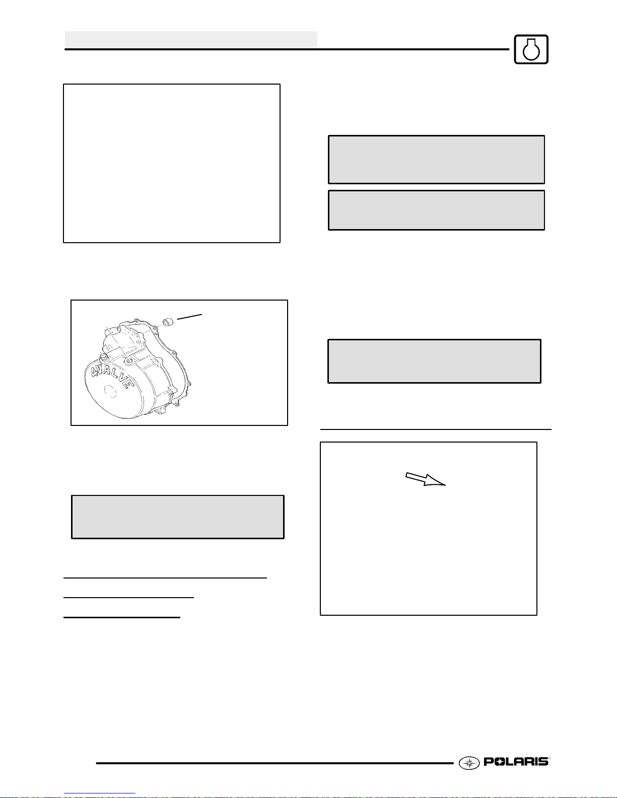
ENGINE
Starter Drive
1. Be sure the washer is positioned on the back of
the drive gear.
Apply StarterDrive
Grease to Bushing
5. Besure thedowel pins arein placeand install the
rocker shaft assembly.
6. Applya light film of engine oil to thethreads of the
bolts and tighten evenly.
Rocker Shaft Support Tower Bolt Torque:
9 ft. lbs. (12 Nm)
Rocker Shaft Locating Bolt Torque:
6 ft. lbs. (8 Nm)
7. Adjust valves according to the valve adjustment
procedure found in Chapter 2, Maintenance.
8. Apply clean engine oil liberally to the valve
springs, cam chain, rocker arms, and camshaft.
9. Place a new rocker cover gasket on the cylinder
head and install the cover and bolts.
Rocker Cover Bolt Torque:
2. Apply starter drive grease to the drive bushing in
the crankcase and all moving surfaces of the
starter drive mechanism. Install the starter drive.
3. Install recoil housing gasket and recoil housing.
Starter Drive Grease:
(PN 2871460)
ROCKER SHAFT/ROCKER
ARM ASSEMBL
INSTALLA
1. Assemble rocker arms, rocker shaft, and shaft
supports.
2. Install and tighten rocker arm shaft locating bolt.
3. Apply starter drive grease to the cam lobes and
cam follower surfaces.
4. Rotatethe engine untilthe camlobes arepointing
downward.
TION
Y
6 ft. lbs. (8 Nm)
THERMOSTAT INSTALLATION
Install the thermostat with one of the air bleed holes
positioned next to the upper thermostat cover bolt
hole as shown.
3.50
 Loading...