


 User Guide

 TCM3 & TCM5

 Tilt-Compensated Compass Module
Table of Contents
1 COPYRIGHT & WARRANTY INFORMATION ..................................................................................... |
3 |
||
2 PNI CORPORATION’S TCM3 & TCM5................................................................................................ |
4 |
||
2.1 |
PERFORMANCE SPECIFICATIONS ....................................................................................... |
5 |
|
|
2.1.1 |
Heading Specifications ................................................................................................. |
5 |
|
2.1.2 |
Magnetometer Specifications ....................................................................................... |
5 |
|
2.1.3 |
Tilt Specifications.......................................................................................................... |
5 |
|
2.1.4 |
Calibration..................................................................................................................... |
5 |
|
2.1.5 |
Mechanical Specifications ............................................................................................ |
5 |
|
2.1.6 |
I/O Specifications.......................................................................................................... |
6 |
|
2.1.7 |
Power Specifications .................................................................................................... |
6 |
|
2.1.8 |
Environmental Specifications ....................................................................................... |
6 |
2.2 |
MECHANICALS......................................................................................................................... |
7 |
|
|
2.2.1 |
Mechanical Drawing ..................................................................................................... |
7 |
|
2.2.2 |
18 in. Cable Assembly.................................................................................................. |
8 |
3 INSTALLATION OF THE TCM ............................................................................................................. |
9 |
||
3.1 |
ELECTRICAL CONNECTIONS................................................................................................. |
9 |
|
3.2 |
WHERE TO INSTALL.............................................................................................................. |
10 |
|
3.3 |
MECHANICALLY MOUNTING THE TCM............................................................................... |
11 |
|
4 USING THE TCM ................................................................................................................................ |
13 |
||
4.1 |
TCM STUDIO .......................................................................................................................... |
13 |
|
|
4.1.1 |
Install the TCM Studio program onto a Windows system: ......................................... |
13 |
|
4.1.2 |
Connection Tab .......................................................................................................... |
14 |
|
4.1.3 |
Configuration Tab ....................................................................................................... |
14 |
|
4.1.4 |
Calibration Tab ........................................................................................................... |
19 |
|
4.1.5 |
Test Tab...................................................................................................................... |
20 |
|
4.1.6 |
Data Logger Tab......................................................................................................... |
21 |
|
4.1.7 |
System Log Tab ......................................................................................................... |
21 |
4.2 |
USER CALIBRATION.............................................................................................................. |
22 |
|
|
4.2.1 |
Calibration Theory ...................................................................................................... |
23 |
|
4.2.2 |
Hard and Soft Iron Effects .......................................................................................... |
23 |
|
4.2.3 |
Pitch and Roll ............................................................................................................. |
24 |
|
4.2.4 |
Recommended Calibration Procedure For Taking The Minimum Number Of Sample |
|
|
Points |
25 |
|
|
4.2.5 |
Declination Value........................................................................................................ |
27 |
|
4.2.6 |
Other Limitations ........................................................................................................ |
28 |
4.3 |
BINARY PROTOCOL – RS232 INTERFACE ......................................................................... |
29 |
|
|
4.3.1 |
Datagram Structure .................................................................................................... |
29 |
|
4.3.2 |
Parameter Formats..................................................................................................... |
29 |
|
4.3.3 |
Commands & Communication Frames ...................................................................... |
32 |
4.4 |
CODE EXAMPLES .................................................................................................................. |
44 |
|
|
4.4.1 |
Binary TCM High Performance Protocol C Header File & CRC-16 Function ............ |
44 |
|
4.4.2 |
Binary TCM Protocol C++ Communication Examples ............................................... |
47 |
PNI Sensor Corporation |
Doc #1007537 r12 |
TCM3 & TCM5 User ManualSept 2011 |
Page 2 |

1 Copyright & Warranty Information
© Copyright PNI Sensor Corporation 2005
All Rights Reserved. Reproduction, adaptation, or translation without prior written permission is prohibited, except as allowed under copyright laws.
Revised March 2011. For most recent version visit our website at www.pnicorp.com
PNI Sensor Corporation
133 Aviation Blvd, Suite 101
Santa Rosa, CA 95403, USA
Tel: (707) 566-2260
Fax: (707) 566-2261
Warranty and Limitation of Liability. PNI Sensor Corporation ("PNI") manufactures its TCM products (“Products”) from parts and components that are new or equivalent to new in performance. PNI warrants that each Product to be delivered hereunder, if properly used, will, for one year following the date of shipment unless a different warranty time period for such Product is specified: (i) in PNI’s Price List in effect at time of order acceptance; or (ii) on PNI’s web site (www.pnicorp.com) at time of order acceptance, be free from defects in material and workmanship and will operate in accordance with PNI’s published specifications and documentation for the Product in effect at time of order. PNI will make no changes to the specifications or manufacturing processes that affect form, fit, or function of the Product without written notice to the OEM, however, PNI may at any time, without such notice, make minor changes to specifications or manufacturing processes that do not affect the form, fit, or function of the Product. This warranty will be void if the Products’ serial number, or other identification marks have been defaced, damaged, or removed. This warranty does not cover wear and tear due to normal use, or damage to the Product as the result of improper usage, neglect of care, alteration, accident, or unauthorized repair.
THE ABOVE WARRANTY IS IN LIEU OF ANY OTHER WARRANTY, WHETHER EXPRESS, IMPLIED, OR STATUTORY, INCLUDING, BUT NOT LIMITED TO, ANY WARRANTY OF MERCHANTABILITY, FITNESS FOR ANY PARTICULAR PURPOSE, OR ANY WARRANTY OTHERWISE ARISING OUT OF ANY PROPOSAL, SPECIFICATION, OR SAMPLE. PNI NEITHER ASSUMES NOR AUTHORIZES ANY PERSON TO ASSUME FOR IT ANY OTHER LIABILITY.
If any Product furnished hereunder fails to conform to the above warranty, OEM’s sole and exclusive remedy and PNI’s sole and exclusive liability will be, at PNI’s option, to repair, replace, or credit OEM’s account with an amount equal to the price paid for any such Product which fails during the applicable warranty period provided that
(i) OEM promptly notifies PNI in writing that such Product is defective and furnishes an explanation of the deficiency; (ii) such Product is returned to PNI’s service facility at OEM’s risk and expense; and (iii) PNI is satisfied that claimed deficiencies exist and were not caused by accident, misuse, neglect, alteration, repair, improper installation, or improper testing. If a Product is defective, transportation charges for the return of the Product to OEM within the United States and Canada will be paid by PNI. For all other locations, the warranty excludes all costs of shipping, customs clearance, and other related charges. PNI will have a reasonable time to make repairs or to replace the Product or to credit OEM’s account. PNI warrants any such repaired or replacement Product to be free from defects in material and workmanship on the same terms as the Product originally purchased.
Except for the breach of warranty remedies set forth herein, or for personal injury, PNI shall have no liability for any indirect or speculative damages (including, but not limited to, consequential, incidental, punitive and special damages) relating to the use of or inability to use this Product, whether arising out of contract, negligence, tort, or under any warranty theory, or for infringement of any other party’s intellectual property rights, irrespective of whether PNI had advance notice of the possibility of any such damages, including, but not limited to, loss of use, revenue or profit. In no event shall PNI’s total liability for all claims regarding a Product exceed the price paid for the Product. PNI neither assumes nor authorizes any person to assume for it any other liabilities.
Some states and provinces do not allow limitations on how long an implied warranty lasts or the exclusion or limitation of incidental or consequential damages, so the above limitations or exclusions may not apply to you. This warranty gives you specific legal rights and you may have other rights that vary by state or province.
PNI Sensor Corporation |
Doc #1007537 r12 |
TCM3 & TCM5 User Manual – Sept 2012 |
Page 3 |

2 PNI Corporation’s TCM3 & TCM5
Thank you for purchasing PNI’s TCM3 (pn 12606) or TCM5 (pn 12608) tilt-compensated compass module. You have chosen a product that represents the largest step forward in compass technology for many years. The TCM is a state-of-the-art, low power, high performance electronic tilt compensated compass sensor module.
The TCM uses advanced algorithms, with hard iron and soft iron corrections, to provide highly accurate heading information, in any orientation (TCM5 only), at latitudes up to 85 . The output information of the unit will indicate accurate attitude position of the module and can be used in systems requiring full 360 rotation (TCM5 only). This has been accomplished by integrating 3-axis magnetic field sensing, 3-axis tilt sensing, and compass heading into a single module, which is one of the smallest in the market. With its small size, the TCM is capable of fitting into today’s size sensitive systems. These advantages make PNI Corporation’s TCM the choice for applications that require the highest accuracy and performance anywhere in the world.
The TCM combines PNI Corporation’s patented Magneto-Inductive (MI) sensors and measurement circuit technology with a 3-axis MEMS accelerometer for unparalleled cost effectiveness and performance. The magnetic sensors and accelerometers are calibrated to operate from -40 to 85 C; hence the measurement is very stable over temperature and inherently free from offset drift.
The TCM’s advantages make it suitable for many applications, including:
High-performance solid state navigation equipment
High-performance attitude measurement
IMU system integration
3-axis magnetic field sensing
Robotics systems
Laser range finders
Drilling applications
With its many potential applications, the TCM provides a command set designed with flexibility and adaptability in mind. Many parameters are user-programmable, including reporting units, a wide range of sampling configurations, output damping, and more. We hope the TCM will help you to achieve the greatest performance from your target system. Thank you for selecting PNI’s TCM compass.
Note: Several versions of the TCM exist, as the product line has evolved over the years. Throughout this manual the term “TCM” refers to the TCM 3 and TCM 5. Other versions available from PNI include the current TCM XB and TCM 5LT, and the legacy TCM 2.5 and TCM 2.6. (Availability subject to change.)
PNI Sensor Corporation |
Doc #1007537 r12 |
TCM3 & TCM5 User ManualSept 2011 |
Page 4 |

2.1 Performance Specifications
2.1.1 Heading Specifications
|
Parameter |
|
|
TCM3 |
|
|
TCM5 |
|
|
Units |
|
|
|
|
|
|
|
|
|
||||
|
|
|
|
|
|
|
|
|
|
|
|
Accuracy with <65º of tilt |
0.5º |
|
0.3º |
|
|
Deg RMS |
|||||
|
Accuracy with <80º of tilt |
|
|
0.8º |
|
|
0.5º |
|
|
Deg RMS |
|
Resolution |
0.1º |
|
0.1º |
|
|
Deg RMS |
|||||
|
Repeatability[1] |
|
|
0.05º |
|
|
0.05º |
|
|
Deg RMS |
|
Max Dip Angle |
85º |
|
85º |
|
|
Deg |
|||||
[1] Repeatability is based on statistical data at ±3 sigma limit about the mean. |
|
|
|
|
|
|
|||||
2.1.2 Magnetometer Specifications
|
Parameter |
|
|
TCM3 |
|
|
TCM5 |
|
|
Units |
|
|
|
|
|
|
|
|
|
||||
|
|
|
|
|
|
|
|
|
|
|
|
Calibrated Field Measurement Range |
±80 |
|
±80 |
|
|
µT |
|||||
|
Magnetic Resolution |
|
|
±0.05 |
|
|
±0.05 |
|
|
µT |
|
Magnetic Repeatability |
±0.1 |
|
±0.1 |
|
|
µT |
|||||
2.1.3 Tilt Specifications
|
Parameter |
|
|
TCM3 |
|
|
TCM5 |
|
|
Units |
|
|
|
|
|
|
|
|
|
||||
|
|
|
|
|
|
|
|
|
|
|
|
Pitch Accuracy |
0.2º |
|
0.2º |
|
|
Deg RMS |
|||||
|
|
|
|
0.2º for pitch <65º |
|
|
0.2º for pitch <65º |
|
|
|
|
|
Roll Accuracy |
|
|
|
|
0.5º for pitch <80º |
|
|
Deg RMS |
|
|
|
|
|
0.5º for pitch <80º |
|
|
|
|
|
|||
|
|
|
|
|
|
1.0 for pitch <86º |
|
|
|
|
|
|
|
|
|
|
|
|
|
|
|||
|
|
|
|
|
|
|
|
|
|
|
|
Tilt Range |
±80º |
|
|
±90º pitch |
|
Deg |
|||||
|
|
±180º roll |
|
||||||||
|
|
|
|
|
|
|
|
|
|
||
|
Tilt Resolution |
|
|
<0.01º |
|
|
<0.01º |
|
|
Deg |
|
Tilt Repeatability[1] |
0.05º |
|
0.05º |
|
|
Deg RMA |
|||||
1] Repeatability is based on statistical data at ±3 sigma limit about the mean. |
|
|
|
|
|
|
|||||
2.1.4 Calibration
|
Parameter |
|
|
TCM3 |
|
|
TCM5 |
|
|
|
|
|
|
|
|||
|
|
|
|
|
|
|
|
|
Hard Iron Calibration |
|
Yes |
|
Yes |
||||
|
Soft Iron Calibration |
|
|
Yes |
|
|
Yes |
|
2.1.5 Mechanical Specifications
|
|
Parameter |
|
|
TCM3 |
|
|
TCM5 |
|
|
Units |
|
|
|
|
|
|
|
|
|
|
||||
|
|
|
|
|
|
|
|
|
|
|
|
|
|
Dimensions (LxWxH) |
|
3.5 x 4.3 x 1.3 |
|
3.5 x 4.3 x 1.3 |
|
|
cm |
||||
|
|
Weight |
|
|
<7 |
|
|
<7 |
|
|
grams |
|
|
Mounting Options |
|
Screw mounts/Standoffs |
|
Screw mounts/Standoffs |
|
|
|
||||
|
|
Horizontal |
|
Horizontal or vertical |
|
|
|
|
||||
|
|
|
|
|
|
|
|
|
|
|||
|
|
Connector for RS-232 |
|
|
9-pin |
|
|
9-pin |
|
|
|
|
PNI Sensor Corporation |
|
|
|
|
|
Doc #1007537 r12 |
||||||
TCM3 & TCM5 User Manual – Sept 2012 |
|
|
|
|
Page 5 |
|||||||
2.1.6 I/O Specifications
|
Parameter |
|
|
TCM3 |
|
|
TCM5 |
|
|
Units |
|
|
|
|
|
|
|
|
|
||||
|
|
|
|
|
|
|
|
|
|
|
|
Time to Initial Good Data from |
<210 |
|
<210 |
|
|
msec |
|||||
Power On1 |
|
|
|
||||||||
|
Time to Initial Good Data from |
|
|
<80 |
|
|
<80 |
|
|
msec |
|
|
|
|
|
|
|
|
|
||||
|
Sleep Mode1 |
|
|
|
|
|
|
|
|||
|
|
|
|
|
|
|
|
|
|
|
|
|
Maximum Sample Rate2 |
|
~30 |
|
~30 |
|
|
samples/sec |
|||
|
RS-232 Communication Rate |
|
|
300 to 115200 |
|
|
300 to 115200 |
|
|
baud |
|
Output Formats |
|
Binary High Performance Protocol |
|
|
|
||||||
[1]FIR taps set to “0”.
[2]The maximum sample rate is dependent on the strength of the magnetic field, and typically will be from 25 to 32 samples/sec.
2.1.7 Power Specifications
|
Parameter |
|
|
TCM3 |
|
|
TCM5 |
|
|
Units |
|
|
|
|
|
|
|
|
|
||||
|
|
|
|
|
|
|
|
|
|
|
|
Supply Voltage |
|
3.8 to 5 V (unregulated) |
|
3.8 to 5 V (unregulated) |
|
VDC |
|||||
|
Current Draw at |
|
|
20 typical |
|
|
20 typical |
|
|
mA |
|
|
|
|
|
|
|
|
|
||||
|
maximum sample rate |
|
|
|
|
|
|
|
|||
|
|
|
|
|
|
|
|
|
|
|
|
Sleep Mode |
|
0.6 typical |
|
0.6 typical |
|
mA |
|||||
2.1.8 Environmental Specifications
|
Parameter |
|
|
TCM3 |
|
|
TCM5 |
|
|
Units |
|
|
|
|
|
|
|
|
|
||||
|
|
|
|
|
|
|
|
|
|
|
|
Operating Temperature |
|
-40º to 85º |
|
-40º to 85º |
|
C |
|||||
|
Storage Temperature |
|
|
-40º to 85º |
|
|
-40º to 85º |
|
|
C |
|
PNI Sensor Corporation |
Doc #1007537 r12 |
TCM3 & TCM5 User ManualSept 2011 |
Page 6 |
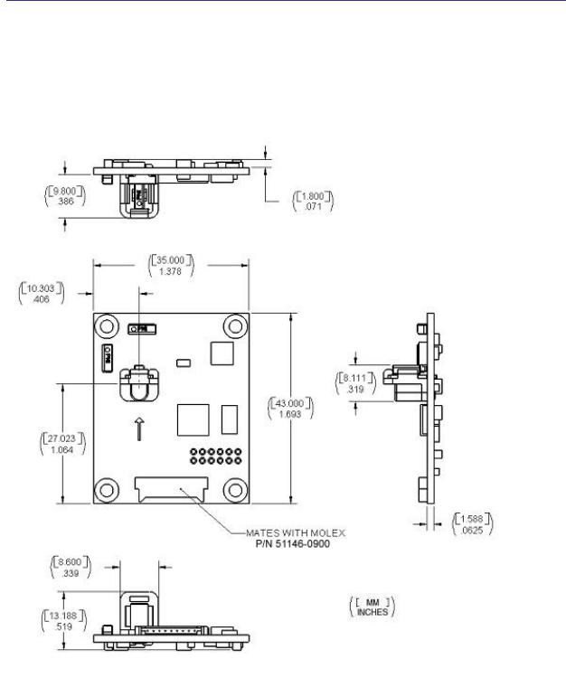
2.2 Mechanicals
2.2.1 Mechanical Drawing
The default orientation for the TCM is for the silk-screened arrow to point in the “forward” direction. That puts the edge opposite of the Molex connector as the front edge of the board.
PNI Sensor Corporation |
Doc #1007537 r12 |
TCM3 & TCM5 User Manual – Sept 2012 |
Page 7 |
2.2.2 18 in. Cable Assembly
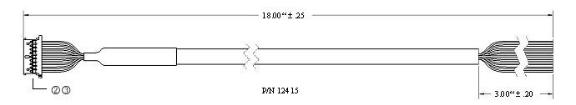
Molex p/n 51146-0900
Molex p/n 50641-8141
TCM Pin Descriptions
|
Pin |
|
|
Wire Color |
|
|
Description |
|
|
|
|
|
|
|
|||
|
|
|
|
|
|
|
|
|
1 |
|
|
Black |
|
Power Ground |
|||
|
2 |
|
|
Gray |
|
|
NC |
|
3 |
|
|
Green |
|
R2-232 Ground |
|||
|
4 |
|
|
Orange |
|
|
NC |
|
5 |
|
|
Violet |
|
NC |
|||
|
6 |
|
|
Brown |
|
|
NC |
|
7 |
|
|
Yellow |
|
TxD |
|||
|
8 |
|
|
Blue |
|
|
RxD |
|
9 |
|
|
Red |
|
5 VDC |
|||
PNI Sensor Corporation |
Doc #1007537 r12 |
TCM3 & TCM5 User ManualSept 2011 |
Page 8 |

3 Installation of the TCM
This section describes how to configure, program, and control the TCM in your host system. To install the TCM into your system, follow these steps:
Make electrical connections to the TCM
Evaluate the TCM using the included TCM Studio Program
Choose a mounting location
Mechanically mount the TCM
Perform user calibration
Before you install the module, it can be evaluated with the TCM Studio outside of your system. Please see section 4.1 TCM Studio.
3.1 Electrical Connections
Included with the TCM Interface Kit is a cable to allow for the unit to be connected to your host system.
On one end of the cable is the connector needed to mate with the TCM3/5. The cable’s wires are color coded as indicated below.
PNI also has a 6-foot cable with a DB9 connector attached. Please contact PNI Corporation for purchasing information.
TCM Pin Descriptions
|
Pin |
|
|
Wire Color |
|
|
Description |
|
|
|
|
|
|
|
|||
|
|
|
|
|
|
|
|
|
1 |
|
|
Black |
|
Power Ground |
|||
|
2 |
|
|
Gray |
|
|
NC |
|
3 |
|
|
Green |
|
R2-232 Ground |
|||
|
4 |
|
|
Orange |
|
|
NC |
|
5 |
|
|
Violet |
|
NC |
|||
|
6 |
|
|
Brown |
|
|
NC |
|
7 |
|
|
Yellow |
|
TxD |
|||
|
8 |
|
|
Blue |
|
|
RxD |
|
9 |
|
|
Red |
|
5 VDC |
|||
PNI Sensor Corporation |
Doc #1007537 r12 |
TCM3 & TCM5 User Manual – Sept 2012 |
Page 9 |

3.2 Where to Install
The TCM’s magnetometers’ wide dynamic range and its sophisticated calibration algorithms allow it to operate in many environments. For optimal performance however, you should mount the TCM with the following considerations in mind:
The TCM’s magnetometers should not saturate
The TCM can be user calibrated to correct for large static magnetic fields created by the host system. However, each axis of the TCM’s magnetometers has a maximum dynamic range of ±80 µT; if the total field exceeds this value for any axis, the TCM will not give accurate heading information. When mounting the TCM, consider the effect of any sources of magnetic fields in the local environment that when added to the earth’s field may saturate the TCM’s sensors. For example, large masses of ferrous metals such as transformers and vehicle chassis, large electric currents, permanent magnets such as electric motors, and so on.
Locate the TCM away from local sources of changing magnetic fields
It is not possible to calibrate for changing magnetic anomalies. Thus, for greatest accuracy, keep the TCM away from sources of local magnetic anomalies that will change with time; for instance, electric equipment that will be turned on and off or nearby ferrous bodies that will be changing positions. Make sure the TCM is not mounted close to cargo or payload areas that may be loaded with large sources of local magnetic fields.
The TCM should be mounted in a physically stable location
Choose a location that is isolated from excessive shock, oscillation, and vibration.
Testing
Testing should be performed in the early stages of development to understand the range of any distortion fields and transients so that component placement can take this into consideration.
To determine the range of field distortion, place the compass in a fixed position, then move/energize suspect components while observing the output to determine when they are an influence.
PNI Sensor Corporation |
Doc #1007537 r12 |
TCM3 & TCM5 User ManualSept 2011 |
Page 10 |
To determine if the mounting locations magnetic field is within the dynamic range of the compass, the following test should be performed:
With the compass mounted, rotate and tilt the systems in as many positions as possible. While doing so, monitor the magnetometer outputs, observing if the maximum dynamic range is exceeded. It is preferable to have some margin before hitting the dynamic range limit of the module.
3.3 Mechanically Mounting the TCM
Refer to the TCM Dimensional Specification later in this manual for the TCM board dimensions and the orientation of the reference frame.
The TCM is factory calibrated with respect to the mounting holes, as shown below, thus it must be aligned within the host system with respect to these mounting holes, not the board edges.
PNI Sensor Corporation |
Doc #1007537 r12 |
TCM3 & TCM5 User Manual – Sept 2012 |
Page 11 |

Mounting Options
The TCM is able to be mounted in various positions to allow for greater flexibility. All reference points are based on the white silk-screened arrow on the top side of the board.
Note: The board depicted below is for illustration purposes only and does not show the actual TCM
board.
TCM3/5 Mounting Options
PNI Sensor Corporation |
Doc #1007537 r12 |
TCM3 & TCM5 User ManualSept 2011 |
Page 12 |

4Using the TCM
TCM Studio
User Calibration
Binary Protocol
Code Examples
4.1 TCM Studio
The TCM Evaluation software communicates with the TCM through the COM port of your PC. It puts an easy-to-use interface onto the Binary command language used by the TCM, so that instead of issuing command codes manually, you can use buttons, check boxes, and dialog boxes. It reads the Binary responses of the TCM output strings and formats its sensor data into labeled and easy-to-read data fields. The program also includes the ability to log and save the outputs of the TCM to a file. All of this is so that you may begin to learn the capabilities of the TCM while using the TCM Studio program’s more friendly interface. Check the PNI website for the latest updates at www.pnicorp.com.
4.1.1 Install the TCM Studio program onto a Windows system:
1.Drag the “TCM Studio.exe” to the working directory of your computer.
2.Move the Quesa plug-in (Quesa.dll) into either the Windows System or System32 folder. Quesa is the OpenGL rendering engine and the 3D Model of the TCMStudio will not run without it.
For Windows 2000/NT copy to: /WinNT/System32 folder
For Windows XP copy to: /Windows/System32 folder
To install the TCM Studio program onto a Mac OSX system:
1.Drag the “TCM Studio” to the working directory of your computer.
2.Move the Quesa plug-in (Quesa) to: /Library/CFMSupport
PNI Sensor Corporation |
Doc #1007537 r12 |
TCM3 & TCM5 User Manual – Sept 2012 |
Page 13 |

4.1.2 Connection Tab
Initial Connection:
1.Select 38400 as the baud rate.
2.Select the serial port the unit is plugged into.
3.Click on the <Connect> button.
4.Once a connection is made the “Connected” light will turn green and the Module, Firmware Version and Serial Number will be displayed.
Change Baud Rate:
1.Select new baud rate for the module.
2.Click on the <Power Down> button.
3.Select same baud rate for the computer.
4.Click on the <Power Up> button.
Change Modules:
Once connection has been made, the TCM Studio will remember the last settings. Any time a module is switched out, clicking on the <Connect> button once the new module is attached will reestablish a
connection as long as the module baud rate is the same as the previous unit.
4.1.3 Configuration Tab
Note: No settings will be changed in the unit until the <SAVE> button has been selected.
Mounting Options:
Note: If the selection is grayed out or not listed the unit connected does not support this feature.
Refer to “Mechanically Mounting – mounting option” section for additional information on mounting options.
Standard: When selected the unit is to be mounted with the main board in a horizontal position (the Z axis magnetic sensor is vertical).
Standard 90 Degrees: When selected the unit is to be mounted with the main board in a horizontal position but rotated so the arrow is pointed 90 degrees clockwise from the front of the host system.
Standard 180 Degrees: When selected the unit is to be mounted with the main board in a horizontal position but rotated so the arrow is pointed 180 degrees from the front of the host system.
Standard 270 Degrees: When selected the unit is to be mounted with the main board in a horizontal position but rotated so the arrow is pointed 270 degrees clockwise from the front of the host system.
PNI Sensor Corporation |
Doc #1007537 r12 |
TCM3 & TCM5 User ManualSept 2011 |
Page 14 |
X Sensor Up: When selected the unit is to be mounted with the main board in a vertical position (the X axis magnetic sensor is vertical).
X Sensor Up Plus 90 Degrees: When selected the unit is to be mounted with the main board in a vertical position (the X axis magnetic sensor is vertical) and rotated 90 degrees clockwise from the front of the host system.
X Sensor Up Plus 180 Degrees: When selected the unit is to be mounted with the main board in a vertical position (the X axis magnetic sensor is vertical) and rotated 180 degrees from the front of the host system.
X Sensor Up Plus 270 Degrees: When selected the unit is to be mounted with the main board in a vertical position (the X axis magnetic sensor is vertical) and rotated 270 degrees clockwise from the front of the host system.
Y Sensor Up: When selected the unit is to be mounted with the main board in a vertical position (the Y axis magnetic sensor is vertical).
Y Sensor Up Plus 90 Degrees: When selected the unit is to be mounted with the main board in a vertical position (the Y axis magnetic sensor is vertical) and rotated 90 degrees clockwise from the front of the host system.
Y Sensor Up Plus 180 Degrees: When selected the unit is to be mounted with the main board in a vertical position (the Y axis magnetic sensor is vertical) and rotated 180 degrees from the front of the host system.
Y Sensor Up Plus 270 Degrees: When selected the unit is to be mounted with the main board in a vertical position (the Y axis magnetic sensor is vertical) and rotated 270 degrees clockwise from the front of the host system.
Z Sensor Down: When selected the unit is to be mounted with the main board in a vertical position (the Z axis magnetic sensor is vertical).
Z Sensor Down Plus 90 Degrees: When selected the unit is to be mounted with the main board in a vertical position (the Z axis magnetic sensor is vertical) and rotated 90 degrees clockwise from the front of the host system.
PNI Sensor Corporation |
Doc #1007537 r12 |
TCM3 & TCM5 User Manual – Sept 2012 |
Page 15 |
Z Sensor Down Plus 180 Degrees: When selected the unit is to be mounted with the main board in a vertical position (the Z axis magnetic sensor is vertical) and rotated 180 degrees from the front of the host system.
Z Sensor Up Plus 270 Degrees: When selected the unit is to be mounted with the main board in a vertical position (the Z axis magnetic sensor is vertical) and rotated 270 degrees clockwise from the front of the host system.
PNI Sensor Corporation |
Doc #1007537 r12 |
TCM3 & TCM5 User ManualSept 2011 |
Page 16 |
North Reference:
Magnetic: When the “Magnetic” radio button is selected, heading will be relative to Magnetic North.
True: When the “True” radio button is selected, heading will be relative to True North. To use North Heading in “True” mode, the declination needs to be set in the “Declination” window. Refer to “Using the TCM Declination Value” section for more information.
Endianess:
Use to select either Big Endian or Little Endian; default is Big Endian.
Filter Settings:
Taps: Use to select either a 0 (no filter), 4, 8, 16, or 32 samples and apply the values to a FIR filter prior to calculating the heading. These filters allow for a much more stable reading, but can make the acquisition of the data by the program slower. The default setting is 32.
Acquisition Parameters:
Mode:
When “Poll” is selected the TCM Studio program requests the data from the unit, and once it has been sent, the program will request the data again at the interval set in the “Poll Time” box. If the time is set to 0 then the TCM Studio will request the data as soon as the previous request has been fulfilled.
When “Push” is selected the unit will be in Interval Mode, which is internal to the unit. Once the unit has been set to Interval Mode and the interval time has been set in the “Interval Time” setting box, the unit will send out the preset data at the desired interval without prompting. If the interval is set to 0 then the unit will send the data as soon as the previous data stream has been sent.
Acquire Time:
The “Acquire Time” setting box sets the time between samples taken by the unit. This is an internal setting that is NOT tied to the time with which the unit transmits the data out to the program or host.
PNI Sensor Corporation |
Doc #1007537 r12 |
TCM3 & TCM5 User Manual – Sept 2012 |
Page 17 |

Flush Filters:
The filtering is set to only update the filter with the last sample taken, for example once the initial 32 samples are taken any new sample is added to the end with the first sample being dropped.
In the case where the “Acquire Time” is set to a value it would be prudent to set the unit to flush the filter prior to calculating the heading. This flushing will require the unit to take 32 new samples to use for the calculation.
Note: If the “Flush Filters” checkbox is checked, it will take longer for the unit to output updated data.
User Cal Settings:
Stability Checking:
By default the unit will wait for the readings to be stable for 3 consecutive readings when in calibration mode prior to saving the sample for use in the calibration. This is why the unit must be held steady between points during the User Calibration. This stability helps to ensure a proper heading and allow for higher accuracy, but it also takes more time. If the user de-selects the check box, then the unit will NOT wait for a stable reading and instead take a reading once the minimum change between points threshold has been met.
Automatic Sampling:
When selected the unit will take a point once the minimum change requirement and the stability check, if selected, has been satisfied. If the user wants to have more control over when the point will be taken then Auto Sampling should be deselected. Once deselected, the <Take Sample> button on the Calibration tab will be active. Selecting the <Take Sample> button will indicate to the unit to take a sample once the minimum requirements are met.
Calibration Points:
The user can select the number of points to take during a calibration. The minimum number of points needed for a successful calibration is 12. The unit will need to be rotated through at least 180 degrees in the horizontal plane with a minimum of at least 1 positive and 1 negative Pitch and at least 1 positive and 1 negative Roll as part of the 12 points.
Enable 3D Model:
Some computer systems may not have the graphics capability to render the 3D Model, for this reason it may be necessary to turn off this feature.
PNI Sensor Corporation |
Doc #1007537 r12 |
TCM3 & TCM5 User ManualSept 2011 |
Page 18 |
 Loading...