


RM3100
Table of contents
 Loading...
User Manual
RM3100 & RM2100
Geomagnetic Sensor

PNI Sensor Corporation Doc 1017252 r03
RM3100 & RM2100 Sensor Suite User Manual Page 1 of 45
Table of Contents
1 COPYRIGHT & WARRANTY INFORMATION ............................................................ 3
2 INTRODUCTION .......................................................................................................... 4
3 SPECIFICATIONS ....................................................................................................... 5
3.1 GEOMAGNETIC SENSOR CHARACTERISTICS .......................................... 5
3.2 SEN-XY-F AND SEN-Z-F CHARACTERISTICS ............................................. 6
3.3 MAGI2C CHARACTERISTICS ........................................................................ 7
3.4 DIMENSIONS, PACKAGING, AND PAD & MASK LAYOUT .......................... 8
3.4.1 Sen-XY-f ............................................................................................. 8
3.4.2 Sen-Z-f .............................................................................................. 10
3.4.3 MagI2C ............................................................................................. 12
3.5 SOLDERING ................................................................................................. 13
4 GEOMAGNETIC SENSOR OVERVIEW & SET-UP .................................................. 15
4.1 OVERVIEW ................................................................................................... 15
4.2 LAYOUT ........................................................................................................ 17
4.2.1 Sensor Coil Orientation .................................................................... 17
4.2.2 Local Magnetic Field Considerations ............................................... 18
4.2.3 Other Layout Considerations ............................................................ 19
4.3 MAGI2C PIN-OUT ......................................................................................... 19
4.3.1 General Pins ..................................................................................... 19
4.3.2 SPI Pins ............................................................................................ 21
4.3.3 I
2
C Pins ............................................................................................. 22
4.4 SPI TIMING REQUIREMENTS ..................................................................... 23
4.5 I
2
C REQUIREMENTS .................................................................................... 25
4.5.1 I
2
C Register Write ............................................................................. 25
4.5.2 I
2
C Register Read ............................................................................. 26
5 MAGI2C OPERATION ............................................................................................... 27
5.1 SET THE CYCLE COUNT REGISTERS (0X04 – 0X09) .............................. 28
5.2 INITIATE CONTINUOUS MEASUREMENT MODE (0X01) .......................... 29
5.2.1 Setting the CMM Update Rate with TMRC (0x0B) ........................... 30
5.2.2 Alarm Mode ...................................................................................... 31
5.3 INITIATE A SINGLE MEASUREMENT (0X00) ............................................. 34
5.4 CONFIRM NEW DATA READY .................................................................... 35
5.4.1 STATUS Register (0x34) .................................................................. 35
5.5 READ THE MEASUREMENT RESULTS ...................................................... 35
5.6 TROUBLESHOOTING AND GENERAL INFORMATION ............................. 36
5.6.1 Built-In Self Test Register (0x33) ..................................................... 36
5.6.2 HSHAKE Register (0x35) ................................................................. 37
5.6.3 REVID Register (0x36) ..................................................................... 38
5.7 EXAMPLES USING THE SPI INTERFACE .................................................. 38
5.7.1 Set the Cycle Count Registers ......................................................... 38
5.7.2 Making and Reading Measurements ................................................ 39
5.8 EXAMPLES USING THE I
2
C INTERFACE ................................................... 41
5.8.1 Set the Cycle Count Registers ......................................................... 41
5.8.2 Initiate a Single Measurement .......................................................... 42
5.8.3 Initiate Continuous Measurement Mode ........................................... 42
5.8.4 Read the Measurement Results ....................................................... 42

PNI Sensor Corporation Doc 1017252 r03
RM3100 & RM2100 Sensor Suite User Manual Page 2 of 45
List of Figures
Figure 3-1: Sen-XY-f Sensor Dimensions ................................................................................ 8
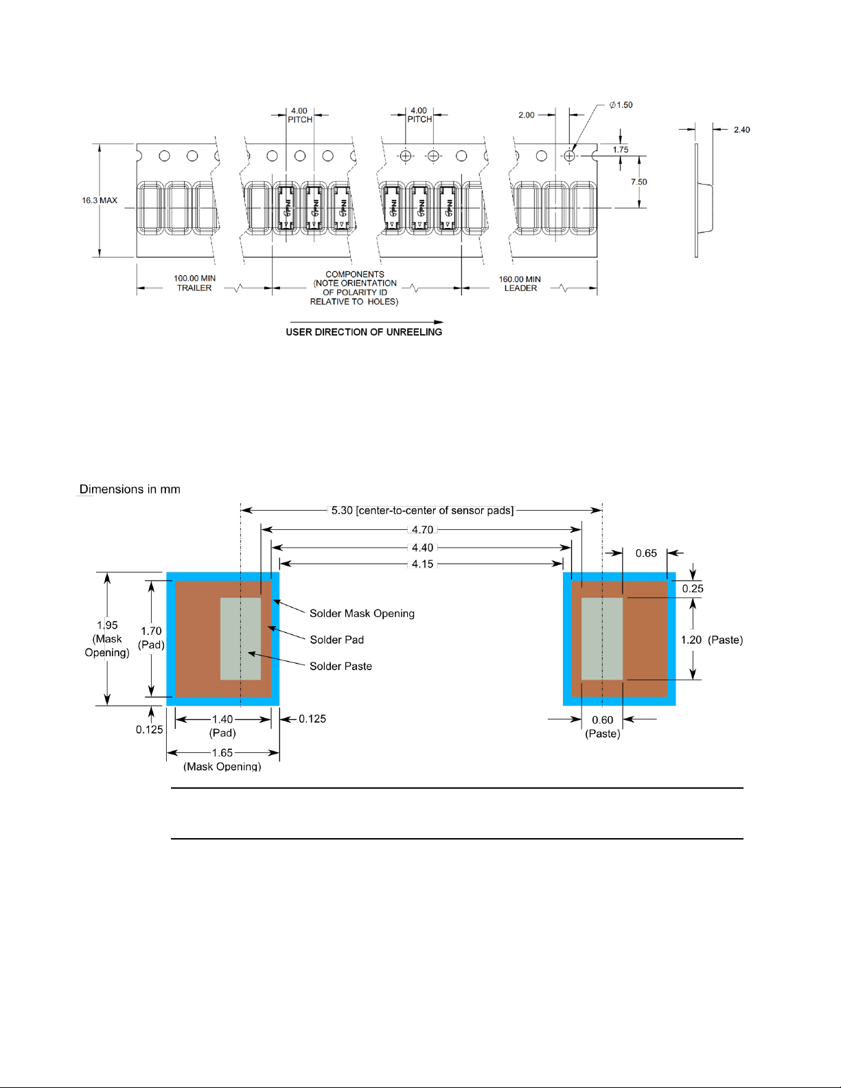
Figure 3-2: Sen-XY-f Tape and Reel Dimensions .................................................................... 9
Figure 3-3: Sen-XY-f Recommended Solder Pad, Paste, & Mask Layout ............................... 9
Figure 3-4: Sen-Z-f Sensor Dimensions ................................................................................. 10
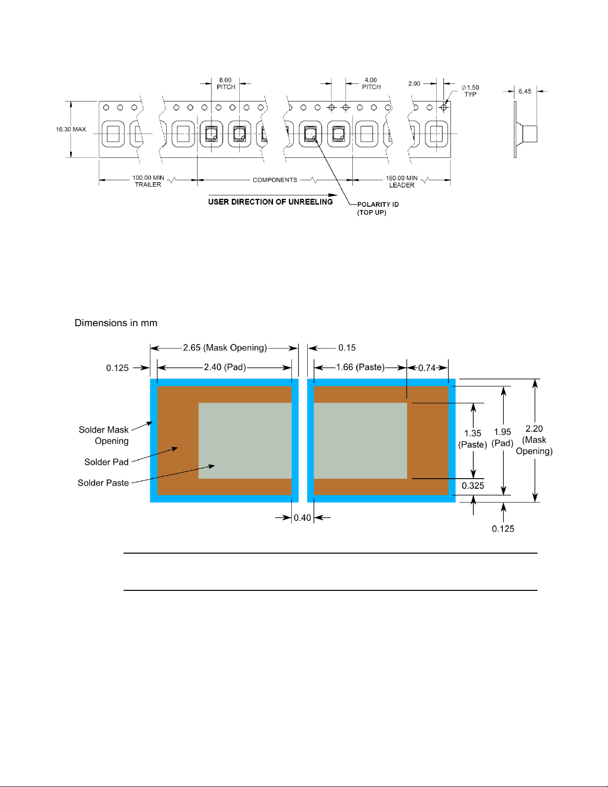
Figure 3-5: Sen-Z-f Tape and Reel Dimensions ..................................................................... 11
Figure 3-6: Sen-Z-f Recommended Solder Pad, Paste, & Mask Layout ................................ 11
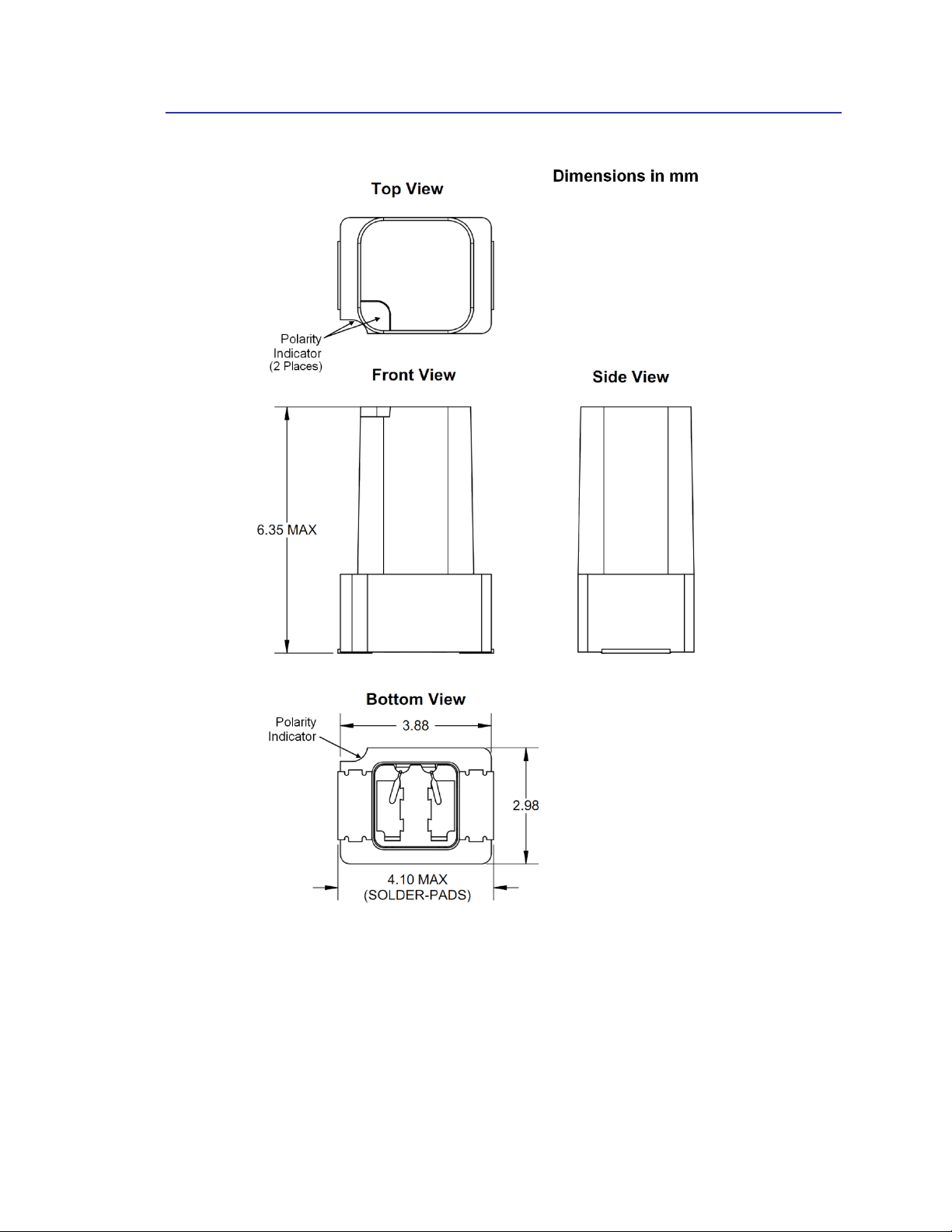
Figure 3-7: MagI2C MLF Mechanical Drawing ....................................................................... 12
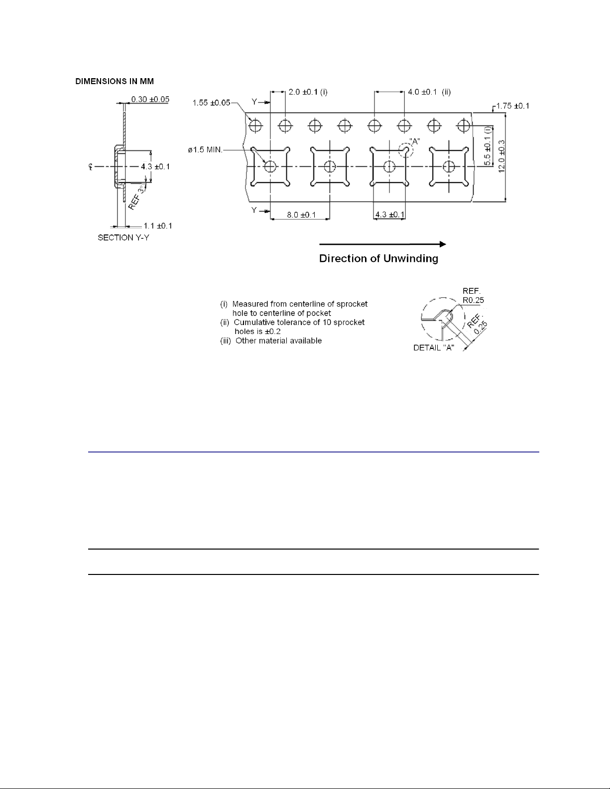
Figure 3-8: MagI2C MLF Tape Dimensions ........................................................................... 13
Figure 3-9: Recommended Solder Reflow Profile .................................................................. 14
Figure 4-1: RM3100 reference schematic – SPI Configuration .............................................. 15
Figure 4-2: RM3100 reference schematic – I
2
C Configuration............................................... 16
Figure 4-3: LR Oscillator Circuit Biasing Diagram .................................................................. 17
Figure 4-4: RM3100 North-East-Down (NED) Sensor Layout ............................................... 18
Figure 4-5: SPI Timing Diagram, CPOL = CPHA = 0 ............................................................. 24
Figure 4-6: SPI Timing Diagram, CPOL = CPHA = 1 ............................................................. 24
Figure 5-1: SPI Activity Sequence Diagram ........................................................................... 39
List of Tables
Table 3-1: Geomagnetic Sensor Performance ......................................................................... 5
Table 3-2: Sen-XY-f and Sen-Z-f Absolute Maximum Ratings ................................................. 6
Table 3-3: Sen-XY-f and Sen-Z-f Characteristics ..................................................................... 6
Table 3-4: MagI2C Absolute Maximum Ratings ....................................................................... 7
Table 3-5: MagI2C Recommended Operating Conditions ....................................................... 7
Table 3-6: Recommended Solder Processing Parameters .................................................... 14
Table 4-1: MagI2C Pin Assignments ...................................................................................... 20
Table 4-2: SPI Timing Specifications ..................................................................................... 25
Table 5-1: MagI2C Register Map ........................................................................................... 27
Table 5-2: Cycle Count Registers ........................................................................................... 28
Table 5-3: Continuous Mode DRDY Options ......................................................................... 30
Table 5-4: CMM Update Rates ............................................................................................... 31
Table 5-5: Alarm Lower and Upper Limit Registers ............................................................... 32
Table 5-6: Alarm Hysteresis Registers ................................................................................... 33
Table 5-7: Absolute vs. Relative Alarm Mode Example ......................................................... 34
Table 5-8: Measurement Results Registers ........................................................................... 36
Table 5-9: BIST Timeout Period ............................................................................................. 37
Table 5-10: BIST LR Periods .................................................................................................. 37

PNI Sensor Corporation Doc 1017252 r03
RM3100 & RM2100 Sensor Suite User Manual Page 3 of 45
1 Copyright & Warranty Information
© Copyright PNI Sensor Corporation 2013
All Rights Reserved. Reproduction, adaptation, or translation without prior written permission is prohibited, except as allowed
under copyright laws.
Revised March 2014: for the most recent version visit our website at www.pnicorp.com
PNI Sensor Corporation
2331 Circadian Way
Santa Rosa, CA 95407, USA
Tel: (707) 566-2260
Fax: (707) 566-2261
Warranty and Limitation of Liability. PNI Sensor Corporation ("PNI") manufactures its Products from parts and components
that are new or equivalent to new in performance. PNI warrants that each Product to be delivered hereunder, if properly used,
will, for ninety (90) days following the date of shipment unless a different warranty time period for such Product is specified: (i)
in PNI’s Price List in effect at time of order acceptance; or (ii) on PNI’s web site (www.pnicorp.com) at time of order
acceptance, be free from defects in material and workmanship and will operate in accordance with PNI’s published specifications
and documentation for the Product in effect at time of order. PNI will make no changes to the specifications or manufacturing
processes that affect form, fit, or function of the Product without written notice to the Customer, however, PNI may at any time,
without such notice, make minor changes to specifications or manufacturing processes that do not affect the form, fit, or function
of the Product. This warranty will be void if the Products’ serial number, or other identification marks have been defaced,
damaged, or removed. This warranty does not cover wear and tear due to normal use, or damage to the Product as the result of
improper usage, neglect of care, alteration, accident, or unauthorized repair.
THE ABOVE WARRANTY IS IN LIEU OF ANY OTHER WARRANTY, WHETHER EXPRESS, IMPLIED,
OR STATUTORY, INCLUDING, BUT NOT LIMITED TO, ANY WARRANTY OF MERCHANTABILITY,
FITNESS FOR ANY PARTICULAR PURPOSE, OR ANY WARRANTY OTHERWISE ARISING OUT OF
ANY PROPOSAL, SPECIFICATION, OR SAMPLE. PNI NEITHER ASSUMES NOR AUTHORIZES ANY
PERSON TO ASSUME FOR IT ANY OTHER LIABILITY.
If any Product furnished hereunder fails to conform to the above warranty, Customer’s sole and exclusive remedy and PNI’s sole
and exclusive liability will be, at PNI’s option, to repair, replace, or credit Customer’s account with an amount equal to the price
paid for any such Product which fails during the applicable warranty period provided that (i) Customer promptly notifies PNI in
writing that such Product is defective and furnishes an explanation of the deficiency; (ii) such Product is returned to PNI’s service
facility at Customer’s risk and expense; and (iii) PNI is satisfied that claimed deficiencies exist and were not caused by accident,
misuse, neglect, alteration, repair, improper installation, or improper testing. If a Product is defective, transportation charges for
the return of the Product to Customer within the United States and Canada will be paid by PNI. For all other locations, the
warranty excludes all costs of shipping, customs clearance, and other related charges. PNI will have a reasonable time to make
repairs or to replace the Product or to credit Customer’s account. PNI warrants any such repaired or replacement Product to be
free from defects in material and workmanship on the same terms as the Product originally purchased.
Except for the breach of warranty remedies set forth herein, or for personal injury, PNI shall have no liability for any indirect or
speculative damages (including, but not limited to, consequential, incidental, punitive and special damages) relating to the use of
or inability to use this Product, whether arising out of contract, negligence, tort, or under any warranty theory, or for infringement
of any other party’s intellectual property rights, irrespective of whether PNI had advance notice of the possibility of any such
damages, including, but not limited to, loss of use, revenue or profit. In no event shall PNI’s total liability for all claims regarding
a Product exceed the price paid for the Product. PNI neither assumes nor authorizes any person to assume for it any other
liabilities.
Some states and provinces do not allow limitations on how long an implied warranty lasts or the exclusion or limitation of
incidental or consequential damages, so the above limitations or exclusions may not apply to you. This warranty gives you
specific legal rights and you may have other rights that vary by state or province.

PNI Sensor Corporation Doc 1017252 r03
RM3100 & RM2100 Sensor Suite User Manual Page 4 of 45
2 Introduction
Thank you for purchasing PNI Sensor Corporation’s RM2100 or RM3100 Geomagnetic Sensor,
pn 90052 or pn 90053, respectively. The RM2100 is comprised of two Sen-XY-f sensor coils,
pn 13104, and a MagI2C ASIC controller, pn 13156, which forms the basis for a 2-axis digital
compass. The RM3100 is the same as the RM2100 but adds a Sen-Z-f sensor coil, pn 13101,
such that compassing measurements are not constricted to the horizontal plane.
PNI’s geomagnetic sensor technology provides high resolution, low power consumption, large
signal noise immunity, a large dynamic range, and high sampling rates. Measurements are stable
over temperature and inherently free from offset drift. The RM3100’s MagI2C ASIC features
both continuous measurement mode and single measurement polling, an alarm feature for
monitoring magnetic field strength, software-configurable resolution and sample rate, and the
ability to operate one, two, or three PNI sensor coils. And it incorporates both I
2
C and SPI
interfaces for system design flexibility.
When implementing an RM3100 or RM2100 Geomagnetic Sensor, each sensor coil serves as the
inductive element in a simple LR relaxation oscillation circuit, where the coil’s effective
inductance is proportional to the magnetic field parallel to the sensor axis. The LR circuit is
driven by the MagI2C ASIC, and the MagI2C’s internal clock is used to measure the circuit’s
oscillation frequency, and hence the magnetic field. Since PNI’s Geomagnetic Sensor works in
the frequency domain, resolution and noise are established cleanly by the number of MagI2C
internal clock counts (cycle counts). In comparison, fluxgate and MR technologies require
expensive and complex signal processing to obtain similar resolution and noise, and in many
respects the geomagnetic sensor’s performance simply cannot be matched. Also, the output from
the MagI2C is inherently digital and can be fed directly into a microprocessor, eliminating the
need for signal conditioning or an analog/digital interface between the sensor and a
microprocessor. The simplicity of PNI’s geomagnetic sensor combined with the lack of signal
conditioning makes it easier and less expensive to implement than alternative fluxgate or
magneto-resistive (MR) technologies.
For more information on PNI’s magneto-inductive sensor technology, see PNI’s whitepaper
“Magneto-Inductive Technology Overview” at http://www.pnicorp.com/technology/papers.

PNI Sensor Corporation Doc 1017252 r03
RM3100 & RM2100 Sensor Suite User Manual Page 5 of 45
3 Specifications
3.1 Geomagnetic Sensor Characteristics
Table 3-1: Geomagnetic Sensor Performance
1
Parameter
Cycle Counts
2
Units
50
100
200
Field Measurement Range
3
-800 to +800
T
Gain
20
38
75
LSB/ T
Sensitivity
50
26
13
nT
Noise
30
20
15
nT
Noise Density @ Max. Single-Axis Sample Rate
1.2
nT/ Hz
Repeatability over 200 T
15
8
8
nT
Hysteresis over 200 T
15
nT
Linearity over 200 T
0.5
%
Maximum Single-Axis Sample Rate
(divide by 3 for max. 3-axis sample rate)
1600
850
440
Hz
Single-Axis Average Current @ 24 Hz Sample
Rate (equivalent to 3-axis @ 8 Hz)
70
135
260
µA
Bias Resistor, R
b
121
External Timing Resistor for Clock, R
EXT
33
k
Circuit Oscillation Frequency
180
kHz
Operating Temperature
-40 to +85
C
Footnotes:
1. Performance values are typical. Performance specifications established with a supply voltage of
3.0 V, a bias resistor of 121 Ω, an external timing resistor of 33 kΩ, and with measurements taken
at room temperature. Other bias resistors, external timing resistors and operating voltages may
be used, but performance will differ from the values listed. Contact PNI for additional information.
2. The cycle count setting (eg. 50 ,100, and 200) is user-configurable and set in the Cycle Count
Registers. See Section 4.1 for a discussion on how the RM3100 works, and Section 5.1 for how
to set the Cycle Count Registers.
3. Field measurement range is defined as the monotonic region of the output characteristic curve.
Field measurement range can be extended using different bias resistors.

PNI Sensor Corporation Doc 1017252 r03
RM3100 & RM2100 Sensor Suite User Manual Page 6 of 45
3.2 Sen-XY-f and Sen-Z-f Characteristics
Table 3-2: Sen-XY -f and Sen-Z-f Absolute Maximum Ratings
Parameter
Minimum
Maximum
Units
Input Pin Current @ 25 C
50
mA
Voltage Across Coil
2.0
VDC
Storage Temperature
-40
+85
C
CAUTION:
Stresses beyond those listed above may cause permanent damage to the device. These
are stress ratings only. Assuming operation with the MagI2C per the guidelines in this
manual, these maximum ratings will not be violated.
Table 3-3: Sen-XY -f and Sen-Z-f Characteristics
Parameter
Min
Typical
Max
Units
Inductance
1
500-600
H
DC resistance @ 25C 15C
30
45
Resistance versus
temperature
0.4
%/C
Weight
Sen-XY-f
0.06 [0.002]
gm [oz]
Sen-Z-f
0.09 [0.003]
gm [oz]
Operating Temperature
-40
+85
C
Footnote:
1. 1 V peak-to-peak across the coil @ 100 kHz sinewave. No DC bias resistance.
Measured orthogonal to Earth’s magnetic field.

PNI Sensor Corporation Doc 1017252 r03
RM3100 & RM2100 Sensor Suite User Manual Page 7 of 45
3.3 MagI2C Characteristics
Table 3-4: MagI2C Absolute Maximum Ratings
Parameter
Minimum
Maximum
Units
Analog/Digital DC Supply Voltage, AV
DD
& DV
DD
-0.3
+3.7
VDC
Input Pin Voltage
-0.3
AV
DD
or DV
DD
VDC
Input Pin Current @ 25C
-10.0
+10.0
mA
Storage Temperature
-40°
+125°
C
CAUTION:
Stresses beyond those listed above may cause permanent damage to the device. These
are stress ratings only. Operation of the device at these or other conditions beyond those
indicated in the operational sections of the specifications is not implied.
Table 3-5: MagI2C Recommended Operating Conditions
Parameter
Symbol
Min
Typ
Max
Units
Analog/Digital DC Supply Voltage
1
AV
DD
,
DV
DD
2.0
3.0
3.6
VDC
Supply Voltage
Difference
(DV
DD
-AV
DD
)
During Operation
∆V
DD_OP
-0.1
0
+0.1
VDC
Analog Unpowered
∆V
DD_OFF
DV
DD
-0.1
DV
DD
DV
DD
+0.1
VDC
Voltage Ripple on AV
DD
or DV
DD
V
DD_ripple
0.05
V
PP
High level input voltage
V
IH
0.7*DV
DD
DV
DD
VDC
Low level input voltage
V
IL
0
0.3*DV
DD
VDC
High level output current
I
OH
-1
mA
Low level output current
I
OL
1
mA
Idle Mode Current
1
µA
Leakage Current @ DV
DD
pin
(AV
DD
=AV
SS
=DV
SS
=0V, DV
DD
=3.6V)
100
nA
Operating Temperature
T
OP
-40
+85
C
Footnote:
1. Please contact PNI if operation at <2.0 V is required.

PNI Sensor Corporation Doc 1017252 r03
RM3100 & RM2100 Sensor Suite User Manual Page 8 of 45
3.4 Dimensions, Packaging, and Pad & Mask Layout
3.4.1 Sen-XY-f
Figure 3-1: Sen-XY-f Sensor Dimensions
PNI Sensor Corporation Doc 1017252 r03
RM3100 & RM2100 Sensor Suite User Manual Page 9 of 45
Dimensions in mm
Full reel is 5000 pcs. Smaller quantities on cut tape.
Tape & reel meets ANSI/EIA standard EIA-418-B
Figure 3-2: Sen-XY-f Tape and Reel Dimensions
Note: PNI recommends a 5 mil stencil. The solder paste area is much smaller than the pad
to reduce sensor tilt and misalignment. The above layout allows for rework: for minimal
footprint, contact PNI.
Figure 3-3: Sen-XY-f Recommended Solder Pad, Paste, & Mask Layout
PNI Sensor Corporation Doc 1017252 r03
RM3100 & RM2100 Sensor Suite User Manual Page 10 of 45
3.4.2 Sen-Z-f
Figure 3-4: Sen-Z-f Sensor Dimensions
PNI Sensor Corporation Doc 1017252 r03
RM3100 & RM2100 Sensor Suite User Manual Page 11 of 45
Dimensions in mm
Full reel is 1200 pcs. Smaller quantities on cut tape.
Tape & reel meets ANSI/EIA standard EIA-418-B
Figure 3-5: Sen-Z-f Tape and Reel Dimensions
Note: PNI recommends a 5 mil stencil. The solder paste area is much smaller than the pad
to reduce sensor tilt and misalignment. The above layout allows for rework: for minimal
footprint, contact PNI.
Figure 3-6: Sen-Z-f Recommended Solder Pad, Paste, & Mask Layout

PNI Sensor Corporation Doc 1017252 r03
RM3100 & RM2100 Sensor Suite User Manual Page 12 of 45
3.4.3 MagI2C
Figure 3-7: MagI2C MLF Mechanical Drawing
PNI Sensor Corporation Doc 1017252 r03
RM3100 & RM2100 Sensor Suite User Manual Page 13 of 45
Dimensions: mm
Full reel is 5000 pcs. Smaller quantities on cut-tape.
Tape & Reel meets ANSI/EIA standard EIA-418
Figure 3-8: MagI2C MLF Tape Dimensions
3.5 Soldering
Figure 3-9 and Table 3-6 provide the recommended solder reflow profile and processing
parameters for RM3100 components. After soldering PNI components to a board, it is
possible to wave solder the opposite side of the PCB.
IMPORTANT: PNI sensor coils require the use of halide-free solder pastes and processes for
reflow and cleaning. Contact PNI if you would like recommendations.
Loading...