

Page 1
Item
Part #
Quantity
Package
SENtral
13658P
<4000
Cut-Tape
SENtral
13658
4000
Tape & Reel
SENtral
Motion Coprocessor
General Description
The SENtral Motion Coprocessor is a
custom integrated circuit that makes it easy
to quickly incorporate, optimize and operate
multiple motion sensors on mobile
consumer electronics devices. SENtral
employs and manages a user-specified
3-axis magnetometer, 3–axis accelerometer,
and 3–axis gyroscope to provide reliable
motion tracking, and accurate heading and
orientation data. SENtral gathers data from
the individual sensors, then integrates and
fuses this data using PNI’s proprietary
Kalman filtering and heuristic algorithms.
Features
Heading Accuracy of 2° rms.
Ultra Low Power Consumption
Continuous Soft and Hard-Iron
Magnetic Auto-Calibration
Magnetic Anomaly
Compensation
I2C Interface – 100 to 3400 kHz
Small Form-Factor
Sensor Flexibility
By offloading the sensor fusion and
interface from a dedicated sensor hub MCU
or the host CPU to SENtral, overall power
requirements are dramatically lowered and
processing power is opened up for other
uses.
These advantages make SENtral the ideal
choice for mobile and consumer electronics
devices desiring ultra-lower power
consumption and best-in-class sensor fusion.
Applications
Cell Phones
Tablets
Ultrabooks
TV Remote Controls
Video Game Controllers
Ordering Information
Page 2

Table of Contents
1 PRODUCT OVERVIEW ............................................................................................... 3
1.1 SENTRAL FEATURES AND BENEFITS ........................................................ 3
1.2 SENTRAL FUNCTIONAL DESCRIPTION ...................................................... 4
2 SENTRAL SPECIFICATIONS ..................................................................................... 6
2.1 PERFORMANCE CHARACTERISTICS ......................................................... 6
2.2 ELECTRICAL CHARACTERISTICS ............................................................... 6
3 LAYOUT ....................................................................................................................... 8
3.1 SYSTEM LAYOUT .......................................................................................... 8
3.2 PIN ASSIGNMENTS ....................................................................................... 9
3.3 SENSOR LAYOUT ........................................................................................ 10
3.4 DEDICATED EEPROM (OPTIONAL) ........................................................... 11
4 I2C INTERFACE ......................................................................................................... 12
4.1 I2C TIMING .................................................................................................... 12
4.2 I2C HOST INTERFACE (HOST BUS) ........................................................... 13
4.2.1 I2C Slave Transfer formats ............................................................... 14
4.3 I2C SENSOR INTERFACE (SENSOR BUS) ................................................. 15
4.4 I2C PULL-UP RESISTANCE ......................................................................... 15
5 OPERATION .............................................................................................................. 16
5.1 POWER-UP AND CONFIGURATION FILE UPLOAD .................................. 17
5.1.1 Configuration File Upload from EEPROM ........................................ 17
5.1.2 Configuration File Upload from Host ................................................ 19
5.2 INITIAL REGISTER SET-UP ......................................................................... 20
5.3 RUNNING IN NORMAL OPERATION .......................................................... 22
5.3.1 Error .................................................................................................. 23
5.3.2 CPUReset ......................................................................................... 24
5.3.3 Read Results .................................................................................... 24
5.4 STANDBY STATE ......................................................................................... 25
5.5 PASS-THROUGH STATE ............................................................................. 25
5.6 TROUBLESHOOTING .................................................................................. 27
5.6.1 Hardware-Related Error Conditions ................................................. 27
5.6.2 Software-Related Error Conditions ................................................... 27
6 SENTRAL CONFIGURATION TOOL ........................................................................ 30
6.1 CONFIGURATION TOOL GENERAL SETTINGS ........................................ 31
6.1.1 SDK Revision ................................................................................... 31
6.1.2 Host Interrupt Pin .............................................................................. 31
6.1.3 EEPROM Max. Upload Speed ......................................................... 31
6.2 CONFIGURATION TOOL SENSOR CONFIGURATION .............................. 31
6.2.1 Sensor .............................................................................................. 31
6.2.2 Interrupt Pin ...................................................................................... 31
6.2.3 Slave Address .................................................................................. 31
6.2.4 Orientation Matrix ............................................................................. 32
6.2.5 Cal Offsets ........................................................................................ 33
7 PACKAGE INFORMATION ....................................................................................... 34
8 ASSEMBLY GUIDELINES ......................................................................................... 36
APPENDIX I – CONFIGURATION FILE IMAGE FORMAT.................................................... 39
APPENDIX II – CONVERTING QUATERNIONS ................................................................... 41
APPENDIX III – PARAMETER TRANSFER ........................................................................... 43
APPENDIX IV – SAMPLE SCHEMATIC SET ........................................................................ 49
PNI Sensor Corporation Doc #1018049 R03
SENtral Technical Data Sheet Page 1
Page 3

List of Figures
Figure 1-1: SENtral Block Diagram .......................................................................................... 4
Figure 3-1: SENtral System Reference Schematic .................................................................. 8
Figure 4-1: I2C Timing Diagram .............................................................................................. 12
Figure 4-2: I2C Slave Write Example ...................................................................................... 14
Figure 4-3: I2C Slave Read Example, with Repeated START................................................ 14
Figure 4-4: I2C Slave Write Register Address Only ................................................................ 14
Figure 4-5: I2C Slave read register from current address ....................................................... 14
Figure 5-1: SENtral Initialization Sequence ............................................................................ 16
Figure 5-2: SENtral Operational States .................................................................................. 17
Figure 5-3: SENtral Normal Operation Flow ........................................................................... 22
Figure 6-1: SENtral Configuration Tool .................................................................................. 30
Figure 7-1: Mechanical Drawing ............................................................................................. 34
Figure 7-2: Tape Dimensions ................................................................................................. 35
Figure 8-1: Typical Solder Mask and Land Pad Parameters ................................................. 37
Figure 8-2: Typical Solder Reflow Profile ............................................................................... 38
Figure A3-1: Parameter Load Process ................................................................................... 44
Figure A3-2: Parameter Retrieve Process ............................................................................. 45
List of Tables
Table 2-1: Performance Characteristics ................................................................................... 6
Table 2-2: Absolute Maximum Ratings .................................................................................... 6
Table 2-3: Operating Conditions............................................................................................... 7
Table 3-1: SENtral Pin Assignments ........................................................................................ 9
Table 3-2: Recommended Power Line Distance from Magnetometer ................................... 11
Table 4-1: I2C Timing Parameters .......................................................................................... 13
Table 4-2: I2C Pull-Up Resistance Table ................................................................................ 15
Table 5-1: Configuration File Upload from EEPROM Registers ............................................ 18
Table 5-2: Configuration File Host Upload Registers ............................................................. 19
Table 5-3: Sample Host Upload Data Order .......................................................................... 20
Table 5-4: Registers for Initial Set-Up .................................................................................... 20
Table 5-5: Normal Operation Registers .................................................................................. 23
Table 5-6: Results Registers .................................................................................................. 24
Table 5-7: Standby Registers ................................................................................................. 25
Table 5-8: Pass-Through Registers........................................................................................ 26
Table 5-9: Hardware-Related Error Indications ...................................................................... 27
Table 5-10: Software-Related Error Indications ..................................................................... 27
Table 5-11: SensorStatus Register Values ............................................................................ 28
Table 5-12: ErrorRegister Values ........................................................................................... 28
Table 5-13: RAMVersion Register Values .............................................................................. 29
Table 8-1: Typical Solder Processing Parameters ................................................................. 38
Table A1-1: Configuration File Image Format ........................................................................ 39
Table A1-2: Configuration File Data Structure ....................................................................... 40
Table A3-1: Registers Used for Parameter Transfer .............................................................. 43
Table A3-2: Parameter Numbers............................................................................................ 46
Table A3-3: DriverID & AlgorithmID Definition ....................................................................... 48
PNI Sensor Corporation Doc #1018049 R03
SENtral Technical Data Sheet Page 2
Page 4

1 Product Overview
The SENtral Motion Coprocessor is an integrated circuit that makes it easy to quickly integrate,
optimize and operate multiple sensors on mobile consumer electronics devices. SENtral manages
and uses data from a user-specified 3-axis gyroscope, 3-axis accelerometer, and 3-axis
magnetometer to provide reliable motion tracking and an accurate compass heading, while
consuming about 1% of the power of a comparable sensor fusion microprocessor.
Note: This revision of the SENtral Technical Datasheet applies to Configuration Files of revision 1.1 or
higher. The Configuration File is discussed in Sections 1.2, 5.1, 5.6.2, and 6, and Appendix I. It is
generated by the SENtral Configuration Tool and is uploaded into SENtral RAM after power up.
1.1 SENtral Features and Benefits
Features and benefits of the SENtral Motion Coprocessor include:
Low power consumption. Offloads sensor processing from the less efficient host
CPU, consuming <1% of the power of a Cortex M0 running a comparable sensor
fusion algorithm. Provides the ability to tailor the tradeoff between power
consumption and motion-tracking performance.
Industry-leading heading accuracy. Unparalleled heading accuracy for consumer
electronics applications.
Continuous hard and soft-iron magnetic auto-calibration. Provides continual
background calibration of the sensors. Leverages PNI’s more than 20 years of
experience and expertise in magnetic measurement.
Magnetic anomaly compensation. Heading and motion tracking is unaffected by
magnetic anomalies such as rebar in buildings, desks, speakers etc., that can easily
throw off the accuracy. SENtral recognizes and compensates for these anomalies.
Sensor flexibility. Works with common consumer electronic MEMS motion sensors,
so system designers can choose the sensors most appropriate for their systems.
Small form-factor. 1.6x1.6x0.5 mm chip-scale package on 0.4 mm pitch. Uses little
PCB real estate, allowing for painless integration.
I2C interface. Uses the industry-standard I2C protocol to interface to the sensors and
the host, so system integration is straightforward. Standard, Fast, Fast Plus, and High
Speed are supported on the host bus.
Outputs. SENtral outputs quaternions, Euler angles (heading, pitch, & roll), and
sensor data (rotational velocity, linear acceleration, & magnetic field).
PNI Sensor Corporation Doc #1018049 R03
SENtral Technical Data Sheet Page 3
Page 5
1.2 SENtral Functional Description
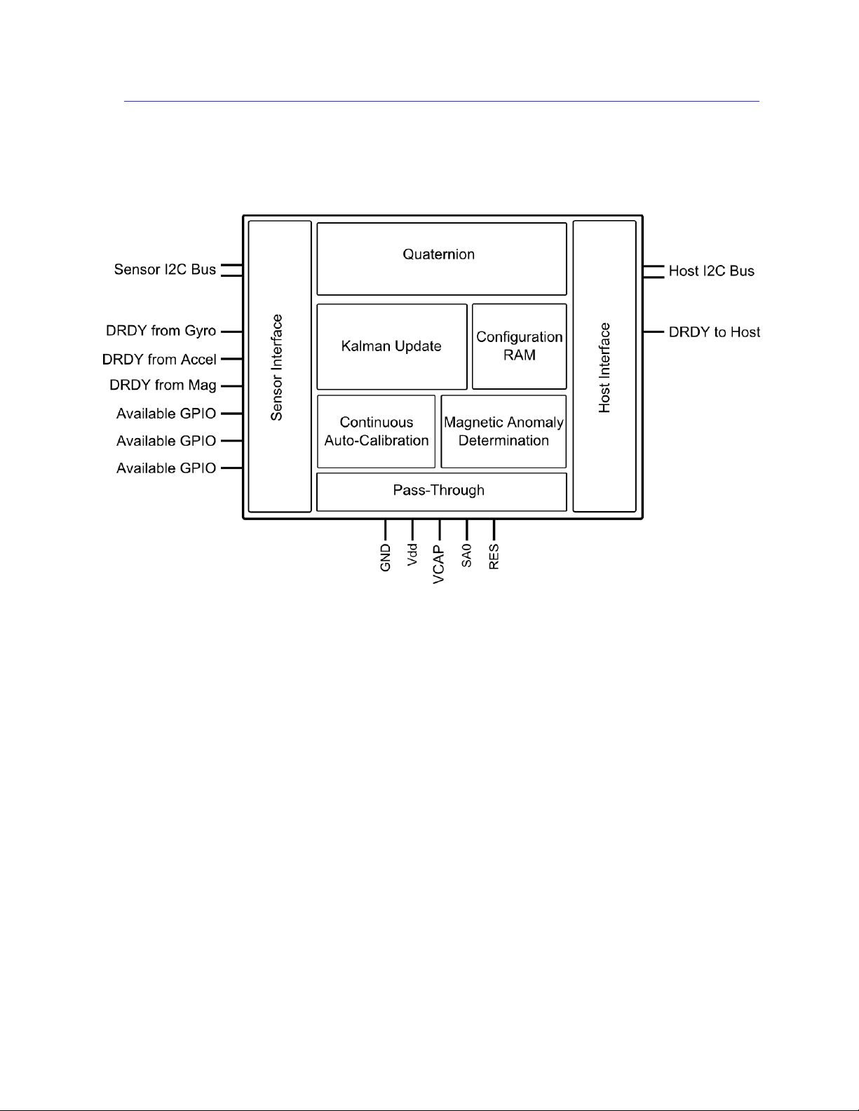
Figure 1-1 provides a diagram of SENtral’s primary functional blocks, and a brief description
of these functional blocks follows.
Figure 1-1: SENtral Block Diagram
Quaternion generates the orientation output, where the actual orientation outputs can
be quaternions or Euler angles (heading, pitch, & roll). The outputs are updated at a
rate limited to the gyro output data rate (ODR), to a maximum of 400 Hz.
Kalman Update fuses data from the 3-axis gyroscope, 3-axis accelerometer, and 3-
axis magnetometer, plus data from the magnetic anomaly determination and
continuous auto-calibration blocks to generate intelligent orientation updates. The
Kalman update involves a sophisticated multi-state Kalman algorithm.
Continuous Hard and Soft-Iron Auto-Calibration. SENtral is the only product in
the market that auto-calibrates for both hard-iron and soft-iron magnetic distortions.
While others may calibrate for hard-iron distortion, soft-iron distortion is more
difficult to correct for, and it can be caused by EMI shielding tape and other shielding
materials widely used in mobile and consumer electronic devices. It is important to
correct for soft-iron distortions since these can contribute up to 90° of error.
Additionally, since a host system’s magnetic signature can change over time and
temperature, SENtral’s continuous auto-calibration ensures accuracy all the time.
PNI Sensor Corporation Doc #1018049 R03
SENtral Technical Data Sheet Page 4
Page 6

Magnetic Anomaly Determination establishes if a transient magnetic distortion is
present and accounts for it.
Configuration RAM allows for customizing SENtral to match the specific sensors
being used and allows the user to tailor certain parameters for their specific system.
The SENtral Configuration Tool generates the SENtral Configuration File, and this is
subsequently uploaded into SENtral’s Configuration RAM.
Pass-Through allows for direct communication with devices on the sensor bus by
connecting SENtral’s I2C Host Interface to the Sensor Interface.
Host Interface communicates with the host system. Data is transmitted between the
host and SENtral via the host I2C bus, in which the host acts as the master and
SENtral acts as a slave device. SENtral signals the host that new data is available by
sending an interrupt signal on the host DRDY line.
Sensor Interface communicates primarily with the sensors. Sensor data is
transmitted from the sensors to SENtral via the sensor I2C bus, in which SENtral acts
as the master and the sensors as the slave devices.
PNI Sensor Corporation Doc #1018049 R03
SENtral Technical Data Sheet Page 5
Page 7

Parameter
Minimum
Typical
Maximum
Units
Heading Accuracy
2
° rms
Output Data Rate
200
400
Hz
Parameter
Symbol
Minimum
Maximum
Units
Supply Voltage
VDD
-0.3
+3.6
VDC
Input Pin Voltage
VIN
GND – 0.3
VDD + 0.3
VDC
ESD
Human Body Model
HBM
-2000
+2000
V
Machine Model
MM
-200
+200
V
Storage Temperature
-50°
+150°
C
2 SENtral Specifications1
2.1 Performance Characteristics
Table 2-1: Performance Characteristics
2.2 Electrical Characteristics
Table 2-2: Absolute Maximum Ratings
CAUTION:
Stresses beyond those listed above may cause permanent damage to the device. These
are stress ratings only. Operation of the device at these or other conditions beyond those
indicated in the operational sections of the specifications is not implied.
Footnote
1. Specifications subject to change.
PNI Sensor Corporation Doc #1018049 R03
SENtral Technical Data Sheet Page 6
Page 8

Parameter
Symbol
Min
Typical
Max
Units
Supply Voltage
VDD
1.6 3.3
VDC
Power-On Reset Threshold, V
REG>VPOR
V
POR
V
REG
– 0.125
VDC
High Level Input Voltage
VIH
0.7*VDD
VDD
VDC
Low Level Input Voltage
VIL 0
0.3*VDD
VDC
High Level Output Current, VOH = VDD – 0.3V
IOH
-1
mA
Low Level Output Current, VOL = 0.3V
IOL 1
mA
Current
Consumption @
1.8 VDD
Normal Operation1
100 – 300
µA
Pass-Through State2
45
µA
Standby State
7
µA
I2C Interface
Data Rate3
Host Bus
3400
kbits/sec
Sensor Bus
1000
kbits/sec
Pass-Through
400
kbits/sec
Decoupling Capacitor (ESR <2)
C
reg
0.33
0.5
1.8
µF
Operating Temperature
TOP
-40
+25
+85
C
Table 2-3: Operating Conditions
Footnotes:
1. SENtral’s current consumption in normal operation is dependent on a number of variables,
including the sensor update rates and the I2C sensor bus rate. The range given will be
typical for most customers. There is a trade-off between sensor update rates and current
consumption, as more frequent sensor update rates result in improved motion-tracking
performance, while less frequent sensor update rates result in reduced current
consumption. Faster I2C sensor bus rates result in lower current consumption.
2. Pass-Through current consumption assumes SENtral previously was in Standby State,
which is recommended, and a sensor bus rate of 400 kbits/s (Fast mode).
3. SENtral’s I2C Host Interface supports Standard, Fast, Fast Plus, and High Speed Modes.
High Speed Mode (3400 kHz) is supported with a reduced range of VDD and bus
capacitance. SENtral’s I2C sensor bus interface supports Standard, Fast, and Fast Plus
Modes. Pass-Through State, which connects the sensor bus and host bus, supports
Standard and Fast Modes.
PNI Sensor Corporation Doc #1018049 R03
SENtral Technical Data Sheet Page 7
Page 9

3 Layout
3.1 System Layout
Figure 3-1 provides a basic reference schematic for connecting SENtral with the host system
and the various sensors.
Figure 3-1: SENtral System Reference Schematic
A few points on system layout.
SENtral communicates with the sensors as the master via a dedicated I2C sensor bus.
The layout shows a discrete magnetometer, accelerometer, and gyroscope. SENtral
also works with combo sensors, such as a single 9-axis sensor or a combo gyro/accel
with a discrete magnetometer.
SENtral acts as a slave on the host system’s I2C bus. This does not need to be a
dedicated bus, although it is shown this way in the schematic. SA0 establishes
SENtral’s slave address when communicating with the host. It is shown set to
ground, but can be set HIGH instead. See Section 4.2.
The pull-up resistance on the I2C lines depends on the number of devices on the bus
and the bus speed. Normally 4.7 kΩ is appropriate for Standard or Fast modes (≤400
kbit/sec). See Section 4.4.
There are three dedicated sensor interrupt lines between the sensors and SENtral, and
one interrupt line between the host and SENtral. The default GPIO assignments are
shown, but these can be altered with the SENtral Configuration Tool. See Section 6.
PNI Sensor Corporation Doc #1018049 R03
SENtral Technical Data Sheet Page 8
Page 10

Pin#
Pin Name
I/O Type*
Description
D1
VDD
PWR
Supply voltage
D3
VCAP
PWR
External compensation capacitor for internal core
voltage regulator
D2
GND
PWR
Ground
C3
SA0
I
I2C slave address bit [0]
B1
SCLS
IO
I2C host bus SCL clock line
A1
SDAS
IO
I2C host bus SDA data line
B4
SCLM
IO
I2C sensor bus SCL clock line
A4
SDAM
IO
I2C sensor bus SDA data line
D4
GPIO[0]
IO / PUPD
General Purpose IO – Default mag interrupt
C4
GPIO[1]
IO / PUPD
General Purpose IO – Default accel interrupt
A3
GPIO[2]
IO / PUPD
General Purpose IO – Default gyro interrupt
B3
GPIO[3]
IO / PUPD
General Purpose IO – Default not connected
A2
GPIO[4]
IO / PUPD
General Purpose IO – Default not connected
B2
GPIO[5]
IO / PUPD
General Purpose IO – Default not connected
C1
GPIO[6]
IO / PUPD
General Purpose IO – Default host interrupt
C2
RES
-
Not Used – Connect to Ground
3.2 Pin Assignments
SENtral’s pin-out is a 4x4 ball-grid array, as defined in Figure 7-1. The table below provides
the pin assignments.
Table 3-1: SENtral Pin Assignments
*I/O Types are:
PWR: Power supply Connections
I: Digital Input
IO: Digital Input / Output
PU: Pull-Up
PD: Pull-Down
PNI Sensor Corporation Doc #1018049 R03
SENtral Technical Data Sheet Page 9
Page 11

3.3 Sensor Layout
SENtral provides for considerable flexibility in sensor orientation and layout, but there are
some basic requirements, as given below.
All three axes of a sensor must be orthogonal to each other. This is by-design for
most accelerometers, gyroscopes, and magnetometers.
A sensor’s X axis and Y axis should act parallel to the primary plane of the
motherboard. A sensor’s Z axis should act perpendicular to the primary plane.
Either a sensor’s X axis or Y axis should align parallel to the line-of-sight of the
motion-tracking device.
It is NOT necessary that the gyroscope, accelerometer, and magnetometer have their
same-axis sensors (i.e. all X-axis sensors) point in the same direction, since sensor
orientation is configured when running the SENtral Configuration Tool and stored in
the SENtral Configuration File.
Assuming the Orientation Matrix is properly input in the SENtral Configuration Tool,
SENtral will output data conforming to a North-East-Down (NED) convention. To convert
to East-North-Up (ENU) see Appendix II – Converting Quaternions.
In addition to the requirements listed above, other recommendations regarding sensor layout
are given below. These represent good practices, but are not mandatory.
Accelerometer
o Locate the accelerometer near the expected center of rotation of the device to
minimize rotational accelerations being interpreted as linear accelerations.
Magnetometer
o Locate the magnetometer >1 cm away from magnetic sources (hard-iron), such as
speaker magnets or known magnetized metals. If uncertain about whether a
component is a magnetic source, check it with a Gauss meter if possible.
o For non-magnetic components, try to avoid placing wireless antenna, power
capacitors, inductors, ferrite beads, and components using ferromagnetic materials
(Fe, Co, Ni) within 1 cm of the magnetometer. Examples of components in a cell
phone which typically contain ferromagnetic materials are the memory card slot,
battery, frame, electrical and magnetic noise shields, connectors, and hinges.
o Materials that are magnetically transparent, and thus relatively safe, include
aluminum, gold, titanium, copper, brass, and magnesium. Most stainless steel
alloys have relatively weak magnetic properties and are not as safe as those just
listed, but don’t need as much attention as ferromagnetic materials.
o Locate high-frequency signal lines away from the magnetometer.
o Locate power lines away from the magnetometer, per the table below.
PNI Sensor Corporation Doc #1018049 R03
SENtral Technical Data Sheet Page 10
Page 12

Current (mA)
Recommended
Distance (mm)
2
0.2
10 1 50 5 100
10
200
20
Table 3-2: Recommended Power Line Distance from Magnetometer
3.4 Dedicated EEPROM (Optional)
A crucial step in using the SENtral coprocessor is uploading the SENtral Configuration File
into SENtral’s RAM. This file contains information on how the sensor system is configured
in the user’s system, and is generated with the SENtral Configuration Tool, as discussed in
Section 6. The Configuration File can be manually uploaded from non-volatile memory in
the host CPU or automatically uploaded from a dedicated EEPROM. The primary
advantages of using a dedicated EEPROM are freeing up host processor memory and
minimizing the time from power-up until the upload is complete. The advantages of using
host CPU memory are no additional cost and no additional system footprint requirement.
If implementing a dedicated EEPROM, connect it to SENtral as a slave device on the sensor
bus, in parallel with the sensors shown in Figure 3-1. The EEPROM upload rate should be
set with the SENtral Configuration Tool (see Section 6.1.3). Faster is generally better,
although the sensor bus rate is limited to 1 Mb/sec. Writing the Configuration File onto the
EEPROM can be accomplished either using an EEPROM programmer or by writing to the
EEPROM from the host while SENtral is in Pass-Through State.
The primary EEPROM requirements are:
≥320 Kbit (40 Kb x 8 bits) of memory.
Shifted address of 0xA0, 0xA2, 0xA4, 0xA6, 0xA8, or 0xAA. (Unshifted address of
0x50, 0x52, 0x54, 0x56, 0x58, or 0x5A.)
The following devices have been used with SENtral, but this list is not exhaustive.
Microchip 24LC256T-I/SN
ST M24M01-DRCS
Renesas R1EX24512ASAS0A
PNI Sensor Corporation Doc #1018049 R03
SENtral Technical Data Sheet Page 11
Page 13

4 I2C Interface
Communication with the host processor and sensors is via an I2C interface and interrupt lines.
The SENtral Motion Coprocessor acts as the I2C master with the sensors and as a slave with the
host processor. The sensor interrupt lines let SENtral know when new data is available, while
the host interrupt line lets the host system know when SENtral has updated the quaternions. The
sensor and host output data rates are set by the MagRate, AccelRate, GyroRate, and
QRateDivisor registers.
SENtral’s I2C interface complies with NXP’s UM10204 specification and user manual, rev 04.
Standard, Fast, Fast Plus, and High Speed modes of the I2C protocol are supported by SENtral’s
I2C host interface. Below is a link to this document.
http://www.nxp.com/documents/user_manual/UM10204.pdf
4.1 I2C Timing
SENtral’s I2C timing requirements are set forth below, in Figure 4-1 and Table 4-1. For the
timing requirements shown in Figure 4-1, transitions are 30% and 70% of VDD.
Figure 4-1: I2C Timing Diagram
PNI Sensor Corporation Doc #1018049 R03
SENtral Technical Data Sheet Page 12
Page 14

Standard
Fast
Fast Plus
Units
Symbol
Parameter
Min
Max
Min
Max
Min
Max
f
SCL
SCL Clock
0
100 0 400
0
1000
kHz
tr
SDA & SCL Rise
Time
-
1000
20
300 120
ns
tf
SDA & SCL Fall Time
-
300
20*(VDD/
5.5V)
300
20*(VDD/
5.5V)
120
ns
t
LOW
LOW period of SCL
Clock
4.7 - 1.3 - 0.5
-
s
t
HIGH
HIGH period of SCL
Clock
4.0 - 0.6 - 0.26
-
s
t
HD;STA
Hold time (repeated)
START
4.0 - 0.6 - 0.26
-
s
t
HD;DAT
Data hold time
0 - 0 - 0
-
s
t
SU:DAT
Data set-up time
250 - 100 - 50 - ns
t
SU;STA
Set-Up time for
repeated Start
4.7 - 0.6 - 0.26
-
s
t
SU;STO
Stop set-up time
4.0 - 0.6 - 0.26
-
s
t
BUF
Bus free time between
STOP & START
4.7 - 1.3 - 0.5
-
s
Table 4-1: I2C Timing Parameters
4.2 I2C Host Interface (Host Bus)
The host will control SENtral on the host bus via SENtral’s I2C host interface. The host
interface consists of 2 wires: the serial clock, SCLS, and the serial data line, SDAS. Both
lines are bi-directional. SENtral is connected to the host bus via the SDAS and SCLS pins,
which incorporate open drain drivers within the device. The host bus lines must be
externally connected to a positive supply voltage (DVIO) via a pull-up resistor. See Section
4.4 for more on the pull-up resistor.
SENtral’s 7-bit I2C slave address is 0b010100x, where the most significant 6 bits of the slave
address are pre-defined in hardware and are the same for all SENtral devices. The least
significant bit is user-configurable, using the SA0 pin to set the bit to ‘0’ or ‘1’. For
example, grounding the SA0 pin (‘0’ value) results in the 7-bit address of 0b0101000. This
should be set so the SENtral slave address is unique to any other devices on the host bus.
Note that setting SA0 to ‘1’ requires utilizing microvia technology, as discussed in Section 8.
PNI Sensor Corporation Doc #1018049 R03
SENtral Technical Data Sheet Page 13
Page 15
START
SLAVE ADDRESS
RW
ACK
REGISTER ADDRESS (N)
ACK
DATA TO REGISTER (N)
ACK
DATA TO REGISTER (N+1)
ACK
STOP
S
A6
A5
A4
A3
A2
A1
A0 0 0
R7
R6
R5
R4
R3
R2
R1
R0 0 D7
D5
D4
D3
D2
D1
D0 0 D7
D5
D4
D3
D2
D1
D0 0 P
From Host to SENtral
------------ Data Transferred (n bytes + acknowledge) ------------
From SENtral to Host
START
SLAVE ADDRESS
RW
ACK
REGISTER ADDRESS (N)
ACK
START
SLAVE ADDRESS
RW
ACK
DATA FROM REGISTER (N)
NACK
STOP
S
A5
A4
A3
A2
A1
A0 0 0
R7
R5
R4
R3
R2
R1
R0 0 SR
A6
A5
A4
A3
A2
A1
A0 1 0
D7
D5
D4
D3
D2
D1
D0 1 P
Data Transferred
(n bytes + acknowledge)
START
SLAVE ADDRESS
RW
ACK
REGISTER ADDRESS (N)
ACK
STOP
S
A5
A4
A3
A2
A1
A0 0 0
R7
R5
R4
R3
R2
R1
R0 0 P
START
SLAVE ADDRESS
RW
ACK
DATA FROM REG. (N)
ACK
DATA FROM REG. (N+1)
NACK
STOP
S
A5
A4
A3
A2
A1
A0 1 0
D7
D5
D4
D3
D2
D1
D0 0 D7
D5
D4
D3
D2
D1
D0 1 P
From Host to SENtral
-------------- Data Transferred (n bytes + acknowledge) --------------
From SENtral to Host
Data transfer is always initiated by the host. Data is transferred between the host and
SENtral serially through the data line (SDAS) in an 8-bit transfer format. The transfer is
synchronized by the serial clock line, SCLS. Supported transfer formats are single-byte read,
multiple-byte read, single-byte write, and multiple-byte write. The data line can be driven
either by the host or SENtral. Normally the serial clock line will be driven by the host,
although exceptions can exist when clock-stretching is implemented in Pass-Through State.
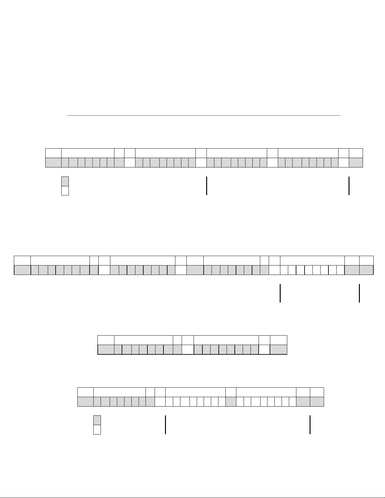
4.2.1 I2C Slave Transfer formats
Figure 4-2 illustrates writing data to registers in single-byte or multiple-byte mode.
Figure 4-2: I2C Slave Write Example
The I2C host interface supports both a read sequence using repeated START conditions,
shown in Figure 4-3, and a sequence in which the register address is sent in a separate
sequence than the data, shown in Figure 4-4 and Figure 4-5.
Figure 4-3: I2C Slave Read Example, with Repeated START
Figure 4-4: I2C Slave Write Register Address Only
Figure 4-5: I2C Slave read register from current address
PNI Sensor Corporation Doc #1018049 R03
SENtral Technical Data Sheet Page 14
Page 16

I2C Mode
Rate
(kbit/s)
Rise Time
(ns)
Max Cb (pF)
4.7 kΩ pull-up
2.4 kΩ pull-up
Standard
100
1000
251.1
491.8
Fast
400
300
75.3
147.5
Fast Plus
1000
120
30.1
59.0
High Speed-1.7 MHz
Clock
1700
80
20.1
39.3
Data
1700
160
40.2
78.7
High Speed-3.4 MHz
Clock
3400
40
10.0
19.7
Data
3400
80
20.1
39.3
4.3 I2C Sensor Interface (Sensor Bus)
SENtral communicates with the accelerometer, gyroscope, and magnetometer over the sensor
bus, where SENtral acts as the I2C master and the sensors act as the I2C slaves. On the
sensor bus, SENtral initiates data transfer and generates the serial clock. SENtral’s I2C
sensor interface supports Standard mode with a rate up to 100 kbit/s, Fast mode with a rate
up to 400 kbit/s, and Fast Plus mode with a rate up to 1000 kbit/s.
The two wires comprising the sensor bus are SDAM, the serial data line, and SCLM, the
serial clock. Both are bidirectional and driven by open drain transistors within SENtral.
Each line should be attached to a pull-up resistor, which is further discussed in Section 4.4.
4.4 I2C Pull-Up Resistance
The pull-up resistor value for both the host and sensor bus will depend on the I2C data rate
and the number of devices on the bus. Table 4-2 provides the maximum acceptable bus
capacitance, as a function of bus rate, which can be accommodated with a 4.7 kΩ or 2.4 kΩ
pull-up resistor. As a general rule, each device connected to the bus represents 10 pF of
capacitance on the bus, so a bus with 4 devices would require a “Max Cb” value of >40 pF.
Table 4-2: I2C Pull-Up Resistance Table
As the table implies, for most Standard and Fast Mode implementations a 4.7 kΩ pull-up
should work well, while a 2.4 kΩ pull-up normally should be used for Fast Plus. See Section
7.1 of NXP’s UM10204 specification for additional information.
http://www.nxp.com/documents/user_manual/UM10204.pdf.
PNI Sensor Corporation Doc #1018049 R03
SENtral Technical Data Sheet Page 15
Page 17
5 Operation
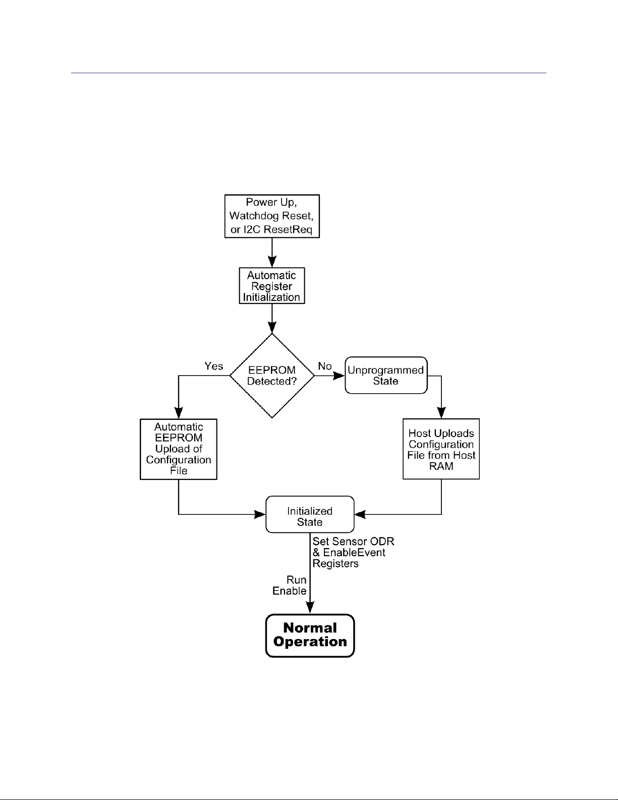
Figure 5-1 provides a flow chart of the initialization process, and a detailed discussion of the
initialization process follows in Section 5.1. For the registers, all multi-byte elements are
stored and transmitted using the Little Endian convention: the least significant byte is
stored at the lowest address and transmitted first over the I2C bus.
Figure 5-1: SENtral Initialization Sequence
PNI Sensor Corporation Doc #1018049 R03
SENtral Technical Data Sheet Page 16
Page 18

Prior to running SENtral, the Configuration File must be uploaded into SENtral’s Configuration
RAM. This file contains information regarding how the user’s sensor system is configured, such
as sensor models, sensor slave addresses, GPIO pin assignments, etc.. The Configuration File is
generated with the SENtral Configuration Tool, as discussed in Section 6. It may be stored in
the host processor’s non-volatile memory or in a dedicated EEPROM connected to SENtral’s
sensor bus. Once the Configuration File is uploaded, SENtral will move into Initialized state.
Once the initialization sequence is complete, there are three states in which SENtral may reside:
Normal Operation, Standby, and Pass-Through. Figure 5-2 indicates the recommended way to
get from one state to another, and these states are discussed in detail in Sections 225.3 (Normal
Operation), 5.4 (Standby), and 5.5 (Pass-Through).
Figure 5-2: SENtral Operational States
5.1 Power-Up and Configuration File Upload
After powering up or issuing a ResetReq command, SENtral automatically initializes the
registers, and then looks for an EEPROM on the sensor bus, as indicated in Figure 5-1.
The Configuration File must now be uploaded. This file contains information on how the
sensor system is configured in the user’s system, and is generated with the SENtral
Configuration Tool, as discussed in Section 6. It can be stored in non-volatile memory in the
host CPU or in a dedicated EEPROM. The primary advantages of using a dedicated
EEPROM are freeing up host processor memory and minimizing the time from powering up
until the upload is complete. The advantages of using the host CPU’s memory are no
additional cost and no additional system footprint requirement. If a dedicated EEPROM is
used, the EEPROM needs to be connected to SENtral as a slave device on the sensor bus.
5.1.1 Configuration File Upload from EEPROM
If a dedicated EEPROM is used to store the Configuration File, then this EEPROM
initially would be loaded with the Configuration File either using an EEPROM
programmer or by writing the file into the EEPROM from the host while SENtral is in
Pass-Through State. This later method also can be used if a new revision of the SENtral
algorithm is available or if the user is testing a variety of sensors and consequently needs
PNI Sensor Corporation Doc #1018049 R03
SENtral Technical Data Sheet Page 17
Page 19

Register Name
Address
Register Value
SentralStatus
0x37
[0] EEPROM. 1 = EEPROM detected
[1] EEUploadDone. 1 = EEPROM upload completed
[2] EEUploadError. 1 = Calculated CRC of EEPROM is
incorrect. Only valid when EEUploadDone = 1.
[3] Idle. 1 = Device in Unprogrammed or Initialized state.
[4] NoEEPROM. 1 = No EEPROM detected.
ResetReq
0x9B
[0] ResetRequest. 1 = Emulate a hard power down/power up.
to change the Configuration File depending on the sensors. As previously mentioned, the
EEPROM should be connected to SENtral via SENtral’s sensor bus.
Table 5-1: Configuration File Upload from EEPROM Registers
SENtral automatically checks the sensor bus after powering up or reseting to see if an
EEPROM is connected on the sensor bus. If an EEPROM is detected, SENtral checks
the first 2 bytes of the EEPROM file, which are fixed for all SENtral Configuration Files,
and if these match then it automatically uploads the SENtral Configuration File. Once
the upload is complete, SENtral enters Initialized State and waits for instructions from the
host. If an EEPROM is not detected, SENtral enters Unprogrammed State.
The host should confirm a successful EEPROM upload by following the steps below:
Read the value from the SentralStatus register.
Check bit [0], the EEPROM bit, to ensure an EEPROM is detected by SENtral.
Check bit [1], the EEUploadDone bit. If this is ‘0’ then the Configuration File upload
is not complete, and reread the SentralStatus register until bit [1] = 1.
Once bit [1] = 1, check bit [2], the EEUpload Error bit. If this is ‘0’, then the upload
was successful.
If the Configuration File upload failed, try the following:
Reinitialize SENtral and retry the process. Send a Reset command by writing 0x01 to
the ResetReq register.
Upload the Configuration File from the host, as discussed in the next section.
Download the Configuration File from the EEPROM and verify its contents, as given
in Appendix I – Configuration File Image Format.
Reload the Configuration File from the host into the EEPROM.
PNI Sensor Corporation Doc #1018049 R03
SENtral Technical Data Sheet Page 18
Page 20

Register Name
Address
Register Value
HostControl
0x34
[0] 1 = RunEnable
[1] 1 = HostUpload Enable
UploadAddr
0x94 to 0x95
Initial RAM address (0x0000)
UploadData
0x96
Data to be uploaded
CRCHost
0x97 to 0x9A
CRC32 of the uploaded data since
host upload was enabled
ResetReq
0x9B
[0] 1 = Reset SENtral
5.1.2 Configuration File Upload from Host
If an EEPROM is not used for storing the Configuration File, then SENtral will enter
Unprogrammed State after failing to identify an EEPROM. The host now should upload
the Configuration File from host memory. The registers involved are given below:
Table 5-2: Configuration File Host Upload Registers
To upload the Configuration File from the host, perform the following transactions:
Write value 0x01 to the ResetReq register. This results in a hard reset of SENtral.
This is unnecessary if SENtral has just been powered up or Reset.
Verify the Configuration File image, as given in Appendix I – Configuration File
Image Format. Specifically:
o Ensure the Magic Numbers are correct.
o Ensure the Uploaded Image Length matches the Uploaded Firmware Image Size.
o Ensure the Upload Image Length is a multiple of 4 bytes.
Write 0x02 to the HostControl register. This sets the UploadEnable bit, which
enables uploading of the Configuration File.
Write the initial RAM address, 0x0000, into the UploadAddr register. This normally
is an unnecessary operation, since the default after powering up or sending a
ResetReq is 0x0000.
Upload the Configuration File to SENtral’s program RAM. This represents the range
from 0x10 to 0x10+UIL-1 in the Configuration File image, as discussed in Appendix
I – Configuration File Image Format. The file is sent one byte at a time, using the
UploadData register. Data can be burst uploaded. Each group of 4 bytes should be
sent in byte-reverse order (i.e. little Endian format). Table 5-3 provides an example.
PNI Sensor Corporation Doc #1018049 R03
SENtral Technical Data Sheet Page 19
Page 21

Byte Order in Config File Image
i
i+1
i+2
i+3
i+4
i+5
i+6
i+7
Config File Image Example
0x01
0x02
0x03
0x04
0x05
0x06
0x07
0x08
Byte Order During Host Upload
i+3
i+2
i+1 i i+7
i+6
i+5
i+4
Example Bye Sent during Upload
0x04
0x03
0x02
0x01
0x08
0x07
0x06
0x05
Register Name
Address
Register Value
MagRate
0x55
Requested magnetometer output data rate
AccelRate
0x56
Requested accelerometer output data rate divided by 10
GyroRate
0x57
Requested gyroscope output data rate divided by 10
QRateDivisor
0x32
Along with GyroRate, establishes output data rate for
quaternion data.
AlgorithmControl
0x54
[0] 1 = StandbyEnable
0 = Disable Standby State
[1] RawDataEnable. 1 = Raw data provided in MX, MY,
MZ, AX, AY, AZ, GX, GY, & GZ.
0 = Scaled sensor data.
[2] HPRoutput. 1 = Heading, pitch, and roll output in QX,
QY, & QZ. QW = 0.0.
0 = Quaternion outputs.
EnableEvents
0x33
‘1’ indicates an interrupt to the host will be generated for
the event.
[0] CPUReset. Non-maskable
[1] Error
[2] QuaternionResult
[3] MagResult
[4] AccelResult
[5] GyroResult
[6] Reserved
[7] Reserved
Table 5-3: Sample Host Upload Data Order
Read the CRCHost register. Compare this to the host-calculated CRC-32 to confirm
a successful upload.
After the reset, write value 0x00 to the HostControl register, which clears the
HostUpload bit and places SENtral in Initialized State.
5.2 Initial Register Set-Up
After the initialization process is complete, it is necessary to configure a few of SENtral’s
registers before running in Normal Operation. These registers are given in Table 5-4.
Table 5-4: Registers for Initial Set-Up
PNI Sensor Corporation Doc #1018049 R03
SENtral Technical Data Sheet Page 20
Page 22

Perform the following:
Set the sensor output data rates (ODRs): MagRate, AccelRate, and GyroRate. If a
sensor rate is set to 0x00, SENtral will shutdown the sensor and disable SENtral
background calibration. There are two major points regarding setting these registers:
o The AccelRate and GyroRate register values should be 1/10th the desired rate,
while the MagRate value should match the desired ODR. For example, if the
desired ODR is 30 Hz for the magnetometer, 100 Hz for the accelerometer, and
200 Hz for the gyroscope, then the respective register values should be 0x1E
(30d), 0x0A (10d), and 0x14 (20d).
o The actual accelerometer and gyro ODRs are limited to the ODRs supported by
the specific sensors. If the AccelRate or GyroRate register values do not
correspond to a supported ODR, then the next highest ODR will be used. For
instance, if the GyroRate register is set to 0x14, which corresponds to 200 Hz, but
the gyro supports 95 Hz, 190 Hz, and 380 Hz, then the actual gyro ODR will be
380 Hz since this is the closest supported rate above that requested by the register.
Establish the quaternion or Euler angle output data rate, where the output data rate
equals GyroRate divided by QRateDivisor. The default for QRateDivisor is 0x00,
which is interpreted as ‘1’ and results in the output data rate equaling GyroRate.
Establish how SENtral’s orientation and sensor data is to be output. The
AlgorithmControl register allows the user to select either quaternion or Euler angles
(heading, pitch, and roll) for orientation outputs, and either scaled or raw sensor data
outputs. The default is 0x00, corresponding to quaternion and scaled sensor data.
Establish which events will trigger an interrupt to the host by configuring the
EnableEvent register. PNI specifically recommends enabling bit [1], the Error
interrupt bit, in addition to whichever other interrupts the user wants.
Example steps to do this are below:
Write 0x640A0F to the MagRate register. Since SENtral automatically increments to
the next register, this also populates the AccelRate and GyroRate registers. This sets
MagRate to 100 Hz, AccelRate to 100 Hz, and GyroRate to 150 Hz.
Write 0x01 to the QRateDivisor Register. This sets the quaternion output data rate to
equal the GyroRate. For writing 0x01 this step is optional, since the default also sets
the quaternion output data rate equal to GyroRate.
Write 0x06 to the AlgorithmControl register. This enables heading, pitch, and roll
orientation outputs and raw sensor data outputs. This step is optional, as the default
register value of 0x00 results in outputs of quaternions and scaled sensor data.
PNI Sensor Corporation Doc #1018049 R03
SENtral Technical Data Sheet Page 21
Page 23

Write 0x07 to the EnableEvents register. This sets up the host to receive interrupts
from SENtral whenever the quaternion results registers are updated, an error has been
detected, or when SENtral needs to be reset.
Note: It is necessary to set the MagRate, AccelRate, AND GyroRate registers to non-zero values for
the SENtral algorithm to function properly and to obtain reliable orientation and scaled sensor data. If
a [Sensor]Rate register is left as 0x00 after power-up, or is changed to 0x00, this effectively disables
that sensor within the SENtral algorithm. Also, the CalStatus, MagTransient, and AlgorithmSlow bits
become undefined.
5.3 Running in Normal Operation
After performing the steps listed above, SENtral is ready to start generating orientation data.
Below is a flow diagram for Normal Operation, followed by the pertinent registers, and then
the steps to follow when running.
Figure 5-3: SENtral Normal Operation Flow
PNI Sensor Corporation Doc #1018049 R03
SENtral Technical Data Sheet Page 22
Page 24

Register Name
Address
Register Value
HostControl
0x34
[0] 1 = RunEnable
0 = Enable Initialized State
EventStatus
0x35
‘1’ indicates a new event has been generated.
[0] CPUReset
[1] Error
[2] QuaternionResult
[3] MagResult
[4] AccelResult
[5] GyroResult
Table 5-5: Normal Operation Registers
Below are the steps to follow when operating in Normal Operation state.
a) Write 0x01 to the HostControl register. This sets the RunEnable bit to ‘1’ and
enables the sensors and the SENtral algorithm.
b) If operating in an interrupt-driven mode, then the host waits until it receives an
interrupt signal from SENtral. Alternatively the host may operate on a polling basis,
rather than an interrupt-driven basis, in which case the interrupt line may not be used.
c) Once an interrupt is received by the host or the host otherwise decides to read new
data, read the EventStatus register.
d) Interpret and act on the EventStatus register in the priority shown in Figure 5-3. If bit
[1], the Error bit, is ‘1’, see Section 5.3.1. If bit [0], the CPUReset bit, is ‘1’, see
Section 5.3.2. If bits [2], [3], [4], or [5], the Results bits, are ‘1’, see Section 5.3.1.
e) Repeat steps c and d until new orientation data is not needed and/or the host decides
to enter a different state.
Note that reading the EventStatus register clears it. It is possible for more than one bit
position to be ‘1’ in the EventStatus register, especially if the host does not always read the
EventStatus register after receiving an interrupt. Similarly, if multiple bits are set to ‘1’ in
the EventStatus register, once the register is read all the bits will be set to ‘0’. For this reason
the EventStatus register should be processed in the priority shown in Figure 5-3, as
information will be cleared for events that are not handled.
5.3.1 Error
In the event of an error, SENtral will trigger an error interrupt and SENtral will enter
Standby State. See the Section 5.6 for recommendations on Troubleshooting and/or reset
SENtral by sending 0x01 to the ResetReq register, at address 0x9B.
PNI Sensor Corporation Doc #1018049 R03
SENtral Technical Data Sheet Page 23
Page 25

Name
Address
(Hex)
Description
Format
Full-Scale Range
QX
00 – 03
Normalized Quaternion – X, or Heading
Float32
0.0 – 1.0, or ±
QY
04 – 07
Normalized Quaternion – Y, or Pitch
Float32
0.0 – 1.0, or ±/2
QZ
08 – 0B
Normalized Quaternion – Z, or Roll
Float32
0.0 – 1.0, or ±
QW
0C – 0F
Normalized Quaternion – W, or 0.0
Float32
0.0 – 1.0
QTime
10 – 11
Quaternion Data Timestamp
UInt16
0 – 2048 msec
MX
12 – 13
Magnetic Field – X Axis, or Raw Mag Data
Int16
±1000 µT when scaled
MY
14 – 15
Magnetic Field – Y Axis, or Raw Mag Data
Int16
±1000 µT when scaled
MZ
16 – 17
Magnetic Field – Z Axis, or Raw Mag Data
Int16
±1000 µT when scaled
MTime
18 – 19
Magnetometer Interrupt Timestamp
UInt16
0 – 2048 msec
AX
1A – 1B
Linear Acceleration – X Axis, or Raw Accel Data
Int16
±16 g when scaled
AY
1C – 1D
Linear Acceleration – Y Axis, or Raw Accel Data
Int16
±16 g when scaled
AZ
1E – 1F
Linear Acceleration – Z Axis, or Raw Accel Data
Int16
±16 g when scaled
ATime
20 – 21
Accelerometer Interrupt Timestamp
UInt16
0 – 2048 msec
GX
22 – 23
Rotational Velocity – X Axis, or Raw Gyro Data
Int16
±5000°/s when scaled
GY
24 – 25
Rotational Velocity – Y Axis, or Raw Gyro Data
Int16
±5000°/s when scaled
GZ
26 – 27
Rotational Velocity – Z Axis, or Raw Gyro Data
Int16
±5000°/s when scaled
GTime
28 – 29
Gyroscope Interrupt Timestamp
UInt16
0.0 – 2.048 sec
5.3.2 CPUReset
SENtral will report a CPUReset event after the ResetReq command has been issued, and
prior to uploading the Configuration File. In this case, SENtral is in Unprogrammed
State and needs the Configuration File to be uploaded. If a dedicated EEPROM is used
to store the Configuration File, then CPUReset should not be encountered as the
Configuration File is automatically uploaded.
5.3.3 Read Results
The Results Registers’ addresses, formats, and full-scale ranges are given below in Table
5-6. For an explanation of how to convert quaternions to the rotation vector, the rotation
matrix, or heading, pitch, and roll (Euler angles), see Appendix II – Converting
Quaternions. The resolution is 32 kHz for all timestamps.
Note: All multi-byte elements are stored and transmitted using the Little Endian convention: the
least significant byte is stored at the lowest address and transmitted first over the I2C bus.
Table 5-6: Results Registers
PNI Sensor Corporation Doc #1018049 R03
SENtral Technical Data Sheet Page 24
Page 26

Register Name
Address
Register Value
AlgorithmControl
0x54
[0] 1 = StandbyEnable
0 = Disable Standby State
AlgorithmStatus
0x38
[0] 1 = SENtral in Standby State
0 = SENtral not in Standby State
5.4 Standby State
In Standby State overall system power consumption is dramatically reduced because both the
SENtral algorithm and the sensors are shut down. Table 5-7 provides the registers associated
with Standby State.
Table 5-7: Standby Registers
The steps to enter and exit Standby State are given below:
Write 0x01 to the AlgorithmControl register. This places SENtral in Standby State.
Read the AlgorithmStatus register. If bit [0] is ‘1’, then SENtral is in Standby State.
This step is optional.
When you are ready to exit Standby State, write 0x00 to the AlgorithmControl
register. This takes SENtral out of Standby State and normally will place it back into
Normal Operation.
Read the AlgorithmStatus register. If bit [0] is ‘0’, then SENtral is not in Standby
State. This step is optional.
5.5 Pass-Through State
SENtral can be configured so the host communicates directly with devices on the sensor bus
by placing SENtral into Pass-Through State. In Pass-Through State, SENtral’s sensor and
host interfaces are connected by internal switches so the host system communicates directly
with the sensors and/or dedicated EEPROM. To enter Pass-Through State, SENtral first
should be in either Standby, Initialized, or Unprogrammed State. Consequently, in PassThrough State the SENtral algorithm, host interrupt line, and sensors are disabled, unless a
sensor is directly turned on by the host. When exiting Pass-Through State, SENtral will
return to its prior state.
Note: When entering Pass-Through State the sensor’s registers retain the values established by
SENtral, and when exiting Pass-Through State any register changes will be retained.
PNI Sensor Corporation Doc #1018049 R03
SENtral Technical Data Sheet Page 25
Page 27

Register Name
Address
Register Value
AlgorithmControl
0x54
[0] 1 = StandbyEnable
0 = Disable Standby State
AlgorithmStatus
0x38
[0] 1 = SENtral in Standby State
0 = SENtral not in Standby State
PassThroughControl
0xA0
[0] 1 = Enable Pass-Through State
0 = Disable Pass-Through State
PassThroughStatus
0x9E
[0] 1 = SENtral in Pass-Through State.
0 = SENtral not in Pass-Through State.
Uses for the Pass-Through State include:
Direct control of sensors, if desired.
Debugging.
Communication with the dedicated EEPROM, if implemented. Specifically, if a new
Configuration File is generated, the host can write this into the EEPROM when in
Pass-Through State.
Since operating in Pass-Through State requires stopping the SENtral algorithm, PassThrough State is not recommended for accessing sensor data unless reliable heading data is
not required. If sensor data and reliable heading data are both desired, scaled sensor data can
be accessed during Normal Operation from the Results Registers, as given in Table 5-6.
Table 5-8 provides the registers associated with Pass-Through State.
Table 5-8: Pass-Through Registers
The steps to go in and out of Pass-Through State are given below.
Write 0x01 to the AlgorithmControl register. This places SENtral in Standby State.
Write 0x01 to the PassThroughControl register. This places SENtral in Pass-Through
State.
Read the PassThroughStatus register. If bit [0] is ‘1’, then SENtral is in Pass-
Through State. This step is optional.
When you are done in Pass-Through State, write 0x00 to the PassThroughControl
register. This terminates Pass-Through mode and returns SENtral to Standby State.
Write 0x00 to the AlgorithmControl register. This takes SENtral out of Standby State
and normally will place it back into Normal Operation.
PNI Sensor Corporation Doc #1018049 R03
SENtral Technical Data Sheet Page 26
Page 28

Register Name
Address
Error Indication
EventStatus
0x35
[0] 1 = CPURest. SENtral Configuration
File needs uploading. See Section 5.1.
SentralStatus
0x37
[2] 1 = EEUploadError. Issue with
uploading from the dedicated EEPROM.
See Section 5.1.
MagRate
0x55
0x00 – Value lost
AccelRate
0x56
0x00 – Value lost
GyroRate
0x57
0x00 – Value lost
Register Name
Address
Error Indication
EventStatus
0x35
[1] 1 = Error.
SensorStatus
0x36
Non-zero value indicates sensor-related error. Check
sensors by communicating in Pass-Through State.
See Table 5-11
SentralStatus
0x37
[3] 1 = Idle. SENtral in Initialized or Unprogrammed
State.
ErrorRegister
0x50
Non-zero value indicated an error. See Table 5-12.
RAMVersion
0x72, 0x73
Unexpected Configuration File revision level.
5.6 Troubleshooting
This section provides guidance in troubleshooting SENtral, and is divided into hardwarerelated and software-related errors.
5.6.1 Hardware-Related Error Conditions
Possible indications of a hardware-related problem are given below in Table 5-9.
Table 5-9: Hardware-Related Error Indications
In the event of such errors, SENtral will enter Standby State, shut down the sensors, and
generate an interrupt to the host. Possible reasons for hardware-related errors include
problems with an external EEPROM upload, power transients detected by power
management, and errors in software detected by Watchdog. Often the error can be
cleared by sending the ResetReq command and reloading the Configuration File.
5.6.2 Software-Related Error Conditions
Possible indications of software-related errors are given below in Table 5-10:
Table 5-10: Software-Related Error Indications
PNI Sensor Corporation Doc #1018049 R03
SENtral Technical Data Sheet Page 27
Page 29

Register Name
Address
Error Indication
SensorStatus
0x36
[0] MagNACK. 1 = NACK from magnetometer
[1] AccelNACK. 1 = NACK from accelerometer
[2] GyroNACK. 1 = NACK from gyroscope
[4] MagDeviceIDErr. 1 = Unexpected DeviceID
from magnetometer
[5] AccelDeviceIDErr. 1 = Unexpected DeviceID
from accelerometer
[6] GyroDeviceIDErr. 1 = Unexpected DeviceID from
gyroscope.
Value
Error Condition
Response
0x00
No error
0x80
Invalid sample rate selected
Check sensor rate settings.
0x30
Mathematical Error
Check for software updates
0x21
Magnetometer initialization failed
This error can be caused by a wrong
driver, physically bad sensor
connection, or incorrect I2C device
address in the driver
0x22
Accelerometer initialization failed
0x24
Gyroscope initialization failed
0x11
Magnetometer rate failure
This error indicates the given sensor
is unreliable and has stopped
producing data.
0x12
Accelerometer rate failure
0x14
Gyroscope rate failure
If the SensorStatus register indicates a non-zero value, then the value provides additional
information on the sensor that is causing a problem, as given in Table 5-11.
Table 5-11: SensorStatus Register Values
If the ErrorRegister indicates a non-zero value, then the value provides additional
information on the sensor that is causing a problem, as given in Table 5-12.
Table 5-12: ErrorRegister Values
If the RAMVersion register values do not correspond to the expected Configuration File
revision level, as given in Table 5-13, certain features or functions that are expected to be
PNI Sensor Corporation Doc #1018049 R03
SENtral Technical Data Sheet Page 28
available may not be available, or they may not function as expected. This normally can
be remedied by generating the latest Configuration File revision level using the SENtral
Page 30

0x72 Register
Value
0x73 Register
Value
RAM Version
(Hex / Decimal)
Config File
Revision
0x04
0x0C
0x0C04 / 3076
1.0
0xD5
0x0C
0x0CD5 / 3285
1.1
0x37
0x0E
0x0E02 / 3639
1.2
Configuration Tool, as discussed in Section 6, and then loading this into an optional
dedicated EEPROM or otherwise uploading it into SENtral.
Table 5-13: RAMVersion Register Values
PNI Sensor Corporation Doc #1018049 R03
SENtral Technical Data Sheet Page 29
Page 31

6 SENtral Configuration Tool
Before using the SENtral Motion Coprocessor, the SENtral Configuration File must be generated
using the SENtral Configuration Tool. As discussed in prior sections, the Configuration File
contains information on how the sensor system is configured in the user’s system.
To access the SENtral Configuration Tool, go to: http://www.sentraltoolkit.com. The tool is for
SENtral customers, and registration is required. Registration requests are reviewed at PNI.
Typically it takes less than one business day to activate a registration request.
The SENtral Configuration Tool provides an intuitive GUI which allows the user to easily
generate the Configuration File. A screen shot of the tool is given in Figure 6-1, and a discussion
of the settings follows. Once the various fields are correctly populated, click <Generate> to
create the SENtral Configuration File. A zip file will automatically download onto your
computer containing the Configuration File, “sentral_[rev]_[mag]_[accel]_[gyro].fw”, and a .cfg
file providing the data input into the Configuration Tool. The .cfg file can be opened with a text
editor. Additionally, the .cfg file can be uploaded into the Configuration Tool by clicking <Load
Config> and then selecting the desired .cfg file. The “GS and M&M Configuration” link opens a
pop-up window with the configurations for the various SENtral M&M and GS modules.
Figure 6-1: SENtral Configuration Tool
PNI Sensor Corporation Doc #1018049 R03
SENtral Technical Data Sheet Page 30
Page 32

6.1 Configuration Tool General Settings
6.1.1 SDK Revision
This establishes the revision of the firmware to be generated. Normally the latest
revision is most desirable, but prior revisions are retained for customers that have
qualified an older revision level.
6.1.2 Host Interrupt Pin
This establishes which GPIO pin is used to send an event interrupt to the host system.
The default is GPIO[6], but any of the GPIO pins can be used for this function.
6.1.3 EEPROM Max. Upload Speed
If the user incorporates a dedicated EEPROM to store the SENtral’s Configuration File,
then this field establishes the maximum data rate the configuration EEPROM can
accommodate. If there is no EEPROM, this setting has no meaning. SENtral
automatically determines if a dedicated EEPROM is present.
6.2 Configuration Tool Sensor Configuration
The sensors attached to SENtral must be configured correctly for SENtral to properly
function. The magnetometer, accelerometer, and gyroscope are configured in a similar
manner, so the parameters discussed below apply to all three sensors.
6.2.1 Sensor
The drop-down menus are used to select the sensor models incorporated into the user’s
system. If a sensor is not listed, then a driver has not been developed for that sensor.
6.2.2 Interrupt Pin
This drop-down menu establishes which General Purpose IO pin is used to send a sensor
interrupt signal to SENtral. As shown in the reference schematic, Figure 3-1, the default
is to use GPIO[0] for the magnetometer, GPIO[1] for the accelerometer, and GPIO[2] for
the gyroscope. However, the GPIO pins are interchangeable and can be configured as is
most convenient for the user.
6.2.3 Slave Address
This establishes the slave address for the respective sensor, and the user needs to input
the sensor’s slave address here. The 7-bit slave address will be provided in the sensor’s
PNI Sensor Corporation Doc #1018049 R03
SENtral Technical Data Sheet Page 31
Page 33

technical data sheet and normally will be a function of 5 or 6 fixed bits and 1 or 2 bits
that are configurable by 1 or 2 of the sensor’s pins.
6.2.4 Orientation Matrix
This matrix defines how the sensors are physically laid out in the host system. The
values are normally 1s, -1s, or 0s. The matrix is used to convert the physical layout into a
north-east-down (NED) convention, where “north” is defined as the line-of-sight or
direction of travel. The matrix is defined as shown in the equation below:
where A through I are the matrix values that need to be populated (1s or 0s), X, Y, and Z
represent the orientation of the x-axis, y-axis, and z-axis sensors, where north is defined
as the line of sight, and NED is the north-east-down convention that the orientation
matrix converts [X, Y, Z] into.
For the accelerometer matrix, it is necessary to multiply the matrix by –1.
Examples:
Below are three examples. The first is if the sensor is laid out in an NED convention,
such that the x-axis points north, the y-axis points east, and the z-axis points down.
Recall that “north” is defined as the line-of-sight or direction of travel. In this case
the orientation matrix is the identity matrix, as given below.
Another common convention is east-north-up (ENU), where the x-axis points east,
the y-axis points north, and the z-axis points up, in which case the orientation matrix
and associated matrix math are given below.
PNI Sensor Corporation Doc #1018049 R03
SENtral Technical Data Sheet Page 32
Page 34

The final example is west-south-down (WSD). This matrix would be appropriate for
an ENU accelerometer, since it incorporates the -1 multiplication factor. The
orientation matrix and associated matrix math are given below.
6.2.5 Cal Offsets
Normally these fields will be ‘0’. However if the user has information indicating a given
model of sensor consistently has a fixed measurement offset, then these fields allow the
user to tailor the SENtral algorithm. For example, assume statistical data from a
manufacturer regarding their accelerometer indicates their z-axis sensor has an average
reading of 1.1 g when actually experiencing 1.0 g of gravitational force. In this case, the
user can enter an offset on the z-axis of 0.1g for the accelerometer. The fields are given
in X, Y, Z order, and the units are as follows:
Magnetometer: 1.0 = +50 T
Accelerometer: 1.0 = +1 g
Gyroscope: 1.0 = +1 radian/second
PNI Sensor Corporation Doc #1018049 R03
SENtral Technical Data Sheet Page 33
Page 35

7 Package Information
Note: For Pin-Out, see
Table 3-1
Figure 7-1: Mechanical Drawing
PNI Sensor Corporation Doc #1018049 R03
SENtral Technical Data Sheet Page 34
Page 36

Figure 7-2: Tape Dimensions
PNI Sensor Corporation Doc #1018049 R03
SENtral Technical Data Sheet Page 35
Page 37

8 Assembly Guidelines
SENtral is provided in a lead-free wafer-level chip-scale package (WL-CSP). General design
guidelines can be found in Amkor’s “Application Note for Surface Mount Assembly of Amkor’s
Eutectice and Lead-Free CSPnl Wafer Level Chip Scale Packages”, which is available from
Amkor’s website. Specific assembly guidelines are discussed below.
Comments specific to SENtral include:
Microvia technology is NOT required if GPIO[3] and GPIO[5] are not used and the
slave address pin, SA0, is set LOW. In this case the slave address pin, C3, should be
connected to C2 (unused), and C2 should be connected to D2, which is GND. Pins
B2, GPIO[5], and B3, GPIO[3], should be left unconnected.
If either GPIO[3] and GPIO[5] are to be used or the slave address pin, SA0, is to be
set HI, then microvia technology is required. Due to SENtral’s ball-grid-array 0.4
mm pitch and 0.26 mm ball diameter, connections to these inner pins should be made
with a via-in-pad design using microvias.
General CSP assembly guidelines for SENtral include:
A non-solder mask defined (NSMD) land pattern is recommended.
Solder mask registration is critical and the correct solder mask opening dimension
should be 50um either side of the copper pad.
The actual size of the copper pad should be between 80% and 100% of the diameter
of the solder ball.
The copper layer thickness should 30 um or less.
The copper pads should be finished with Organic Solderability Preservative (OSP)
coating, such as ENTEK-PLUS Cu 106A.
Standard epoxy glass PCB substrates are compatible. High temperature FR4 is
preferred over standard FR4 for improved package reliability.
PNI Sensor Corporation Doc #1018049 R03
SENtral Technical Data Sheet Page 36
Page 38

Figure 8-1 provides design parameters for a typical SENtral solder mask and pad pattern.
Figure 8-1: Typical Solder Mask and Land Pad Parameters
A typical recommended solder reflow profile is given in Figure 8-2 and the associated processing
parameters are given in Table 8-1, both on the following page. Oven type and tolerances,
thermocouple tolerance, solder type, and the temperature difference across the board will affect
the actual implemented profile.
PNI Sensor Corporation Doc #1018049 R03
SENtral Technical Data Sheet Page 37
Page 39

Parameter
Value
Ramp Up Rate
3°C/second
Preheat Temperature Range
150°C to 180°C
Preheat Time
60 – 180 seconds
Liquidus Temperature
220°C
Time above Liquidus
30 – 90 seconds
Peak Temperature
255°C ±5°C
Time within 5°C of Peak Temperature
10 – 20 seconds
Ramp Down Rate
6°C/second maximum
PB
Figure 8-2: Typical Solder Reflow Profile
Table 8-1: Typical Solder Processing Parameters
PNI Sensor Corporation Doc #1018049 R03
SENtral Technical Data Sheet Page 38
Page 40

Byte Index
Content
Note
0x00
Magic Number Lower Byte
0x2A is expected value
0x01
Magic Number Upper Byte
0x65 is expected value
0x02 & 0x03
Flags
Bit [0] – EEPROMExec
0 = Execute after EEPROM
upload (default)
1 = Do not execute after
EEPROM upload
Bits [8] to [10] – I2CClockSpeed
000 – 1 Mbit/s
001 – 833 kbit/s
010 – 400 kbit/s
011 – 333 kbit/s
100 – 100 kbit/s
Others – 83 kbit/s
Bits [11] to [14] – ROMVerExp.
0001 – version 0x7A8
0010 – version 0x9E6
0x04 to 0x07
CRC32 of uploaded image
Stored in Little Endian Format
0x08 to 0x0B
Reserved
0x00000000
0x0C & 0x0D
Uploaded Image Length (UIL)
Stored in Little Endian Format
0x0E & 0x0F
Reserved
0x0000
0x10 to
0x10+UIL-46
Uploaded Image – Instructions &
Configuration File Data
CRC32 is calculated over
uploaded image
0x10+UIL-45 to
0x10+UIL-1
Uploaded Image –Config. File
Data Structure. See Table A1-2.
Appendix I – Configuration File Image Format
Table A1-1 provides the format for the Configuration File image. While understanding the
Configuration File image format is not mandatory for operation, it can be useful when debugging
errors.
Table A1-1: Configuration File Image Format
PNI Sensor Corporation Doc #1018049 R03
SENtral Technical Data Sheet Page 39
Page 41

Byte Index
Content
Note
0x00
Signature Lower Byte
Value is 0x8B. Can be used to locate
the data structure within the image.
0x01
Signature Upper Byte
Value is 0xC8. Can be used to locate
the data structure within the image.
0x02 to 0x07
Reserved
0x08 & 0x09
RAM Version
Firmware version number
0x0A
Version
Configuration Structure Version
0x0B
Boot Protocol
Used for standalone applications
0x0C to 0x13
PinSelection
Bit 0-3 Host IRQ pin selection
Others – reserved
0x14 to 0x1B
PullSelection
Bit 0 & 1 GPIO0 pull selection
0=no pulls, 1=pull-down, 2=pull-up,
3=keep defaults
Bit 2 & 3 GPIO1 pull selection
Bit 4 & 5 GPIO2 pull selection
Bit 6 & 7 GPIO3 pull selection
Bit 8 & 9 GPIO4 pull selection
Bit 10 & 11 GPIO5 pull selection
Bit 12 & 13 GPIO6 pull selection
Others – reserved
0x1C to 0x2B
Device Name
16 character string
Table A1-2: Configuration File Data Structure
When uploading the Configuration File from a dedicated EEPROM, SENtral first checks the
Magic Number upper and lower bytes to ensure they match the expected values. If they do, then
the upload will commence, and during the upload SENtral calculates the CRC32 value over the
incoming data. At the end of the upload process, the calculated CRC32 value is compared with
the valued stored in the header. If they match the Configuration File has been successfully
uploaded. If the the EEPROMExec bit is set to ‘0’, then the SENtral algorithm automatically
will execute and move SENtral in Initialized state, as shown in Figure 5-1.
PNI Sensor Corporation Doc #1018049 R03
SENtral Technical Data Sheet Page 40
Page 42

Appendix II – Converting Quaternions
SENtral outputs orientation data in quaternions, using a North-East-Down (NED) convention.
This is done to avoid the singularities inherent in using Euler angles (heading, pitch, and roll),
and because the fusion algorithms are easier to implement with quaternions. However, normally
quaternions are not the desired final output format. Most end users will want heading, pitch, and
roll, while Android looks for a rotation vector and generally uses a rotation matrix for
orientation. Plus, Android and Win8 both expect data to be presented in the East-North-Up
(ENU) convention. This appendix discusses how to convert SENtral’s output quaternions into
these other output formats.
Converting from NED to ENU
While the North-East-Down (NED) convention is common in many industries, both Android
and Windows 8 use the East-North-Up convention. Below is the equation to convert from
NED to ENU.
Heading, Pitch, and Roll
Most end users will want orientation data reported as heading, pitch, and roll. Below are the
Excel transformation equations. Note that for other programs, such as Matlab, the ATAN2
arguments may be reversed.
Heading = atan2[(Qx2 – Qy2 – Qz2 + Qw2), 2*(QxQy + QzQw)]
Pitch = asin[-2*(QxQz – QyQw)]
Roll = atan2[(–Qx2 – Qy2 + Qz2 + Qw2), 2*(QxQw + QyQz)]
Where:
Results are in radians.
The quaternions are the outputs from SENtral in NED convention.
Heading increases as the device rotates clockwise around a positive Z axis, and the
range is 0° – 360°. (i.e. it matches what you would expect on a compass.)
Pitch increases when pitching upward and the range is ±180°.
Roll increases when rolling clockwise and the range is ±90°.
PNI Sensor Corporation Doc #1018049 R03
SENtral Technical Data Sheet Page 41
Page 43

Qw2 + Qx2 – Qy2 – Qz2
2*(Qx*Qy + Qw*Qz)
2*(Qx*Qz – Qw*Qy)
R =
2*(Qx*Qy – Qw*Qz)
Qw2 – Qx2 + Qy2 – Qz2
2*(Qy*Qz + Qw*Qy)
2*(Qx*Qz + Qw*Qy)
2*(Qy*Qz – Qw*Qy)
Qw2 – Qx2 – Qy2 + Qz2
Rotation Vector
The rotation vector is the first three elements of the quaternion output, Qx, Qy, and Qz. The
fourth element, Qw, is not included in the rotation vector. The rotation vector in ENU
convention will be the first three elements of Q
Rotation Matrix, or Direction Cosine Matrix (DCM)
, discussed above.
ENU
The rotation matrix, also known as the direction cosine matrix (DCM), can be established
from the quaternion output using the following conversion. Q
values can be substituted
ENU
to give the rotation matrix with an ENU convention.
PNI Sensor Corporation Doc #1018049 R03
SENtral Technical Data Sheet Page 42
Page 44

Register Name
Address
Access
Format
Description
AlgorithmControl
0x54
R/W
[7:0]
[0] StandbyEnable. 1 = Enable Standby state
[1] RawDataEnable. 1 = Raw data provided in
MX, MY, MZ, AX, AY, AZ, GX, GY, & GZ.
0 = Scaled sensor data.
[2] HPRoutput. 1 = Heading, pitch, and roll
output in QX, QY, & QZ. QW = 0.0.
0 = Quaternion outputs.
[7] ParamTransfer. 1 = Enable Parameter
Transfer.
LoadParamByte0
0x60
R/W
Float 8
Parameter value to be loaded – LSB
LoadParamByte1
0x61
R/W
Float 8
Parameter value to be loaded – LSB + 1
LoadParamByte2
0x62
R/W
Float 8
Parameter value to be loaded – MSB – 1
LoadParamByte3
0x63
R/W
Float 8
Parameter value to be loaded – MSB
ParamRequest
0x64
R/W
[7:0]
Bits [0] – [6] provide the parameter number to
be uploaded or retrieved.
[7] Load/Save bit. 1 = Load, 0 = Save.
ParamAcknowledge
0x3A
R/O
[7:0]
Bits [0] – [6] provide the parameter number
that was uploaded or retrieved.
[7] Load/Retrieve bit. 1 = Load, 0 = Retrieve.
RetrieveParamByte0
0x3B
R/O
Float 8
Parameter value read from Sentral – LSB
RetrieveParamByte1
0x3C
R/O
Float 8
Parameter value read from Sentral – LSB + 1
RetrieveParamByte2
0x3D
R/O
Float 8
Parameter value read from Sentral – MSB – 1
RetrieveParamByte3
0x3E
R/O
Float 8
Parameter value read from Sentral – MSB
Appendix III – Parameter Transfer
Note: Implementing the parameter transfer process is not necessary when using SENtral, but can be
useful for enabling a warm start, for setting the sensor ranges to non-default values, and/or for reading
the device driver IDs.
This appendix provides the protocol for implementing SENtral’s parameter transfer process. A
parameter transfer involves the host either loading parameter values into SENtral, or retrieving
parameter values currently used by SENtral.
Register Usage
Table A3-1 provides the registers used for the parameter transfer process.
Table A3-1: Registers Used for Parameter Transfer
PNI Sensor Corporation Doc #1018049 R03
SENtral Technical Data Sheet Page 43
Page 45

The parameter transfer process is invoked and terminated by appropriately setting the
ParamTransfer bit in the AlgorithmControl register. Ten (10) registers are used for the
transfer and for handshaking between SENtral and the host. One set of four registers is
allocated to upload a parameter value to SENtral, and another set of four registers is used to
retrieve a currently saved parameter from SENtral. Values shorter than four bytes can be
transferred using only some of the registers. Two registers implement the handshake
mechanism between SENtral and the host. Note that data is stored in little Endian format.
Parameter Load
Figure A3-1 shows the Parameter Load process by which the host loads parameter data into
SENtral.
Figure A3-1: Parameter Load Process
Initially the parameter values must be written into the LoadParamByte registers followed by
sending a non-zero parameter number into the ParamRequest register. The parameter
numbers are given in Table A3-2. The MSB of the ParamRequest register should be set
to ‘1’ to indicate a Load procedure. All five bytes can be written using a single I2C
PNI Sensor Corporation Doc #1018049 R03
SENtral Technical Data Sheet Page 44
Page 46

transaction. AFTER the first parameter is written, the ParamTransfer bit in the
AlgorithmControl register must be set to ‘1’. Sentral acknowledges receipt of a parameter
value by setting ParamAcknowledge equal to ParamRequest, and the host should check the
ParamAcknowledge register after writing the first parameter.
Once SENtral acknowledges successfully uploading the first parameter, the host can begin
writing the remaining parameters in a loop. Reading the ParamAcknowledge register is
optional for subsequent parameters. The host terminates the load procedure by setting the
ParamRequest register to 0x00 and the AlgorithmControl register’s ParamTransfer bit to ‘0’.
Parameter Retrieve
The Parameter Retrieve flowchart is given in Figure A3-2.
Figure A3-2: Parameter Retrieve Process
The process is initiated by the host writing to the ParamRequest register the desired (nonzero) parameter number. The MSB of ParamRequest register should be ‘0’ to indicate a
Retrieve procedure. After writing to the ParamRequest register, the ParamTransfer bit in
the AlgorithmControl register must be set to ‘1’. Next, the host should perform repetitive
reads of the ParamAcknowledge register until it contains the requested parameter number.
PNI Sensor Corporation Doc #1018049 R03
SENtral Technical Data Sheet Page 45
Page 47

Parameter
Number
Parameter Name
ParamRequest
Value
Load
Retrieve
1 – 35
WarmStart[1] to
WarmStart[35]
0x81 to
0xA3
0x01 to
0x23
36 – 73
Reserved
74
SensorRange[mag:accel]
0xCA
0x4A
75
SensorRange[gyro]
0xCB
0x4B
77
DriverID[mag:accel]
--
0x4D
78
DriverID[gyro]
0x4E
80
AlgorithmID
--
0x50
Now the host can read the RetrieveParamByte registers to obtain the parameter value. Note
the host can read the ParamAcknowledge and RetrieveParamByte registers using a single
five-byte read transaction. Also, the RetrieveParamByte values are given in little Endian
format, such that RetrieveParamByte3 contains the least significant byte of the parameter’s
4-byte float value. The host can continue reading other parameters by varying (normally
incrementing) the parameter number contained in the ParamRequest registers. Reading the
ParamAcknowledge register is optional for subsequent parameters. The procedure is
terminated by the host writing 0x00 to the ParamRequest and AlgorithmControl registers.
Interleaving Parameter Load and Retrieve
The host can interleave the Parameter Load and Parameter Retrieve processes during a single
process invocation. This can be done for each parameter by setting the MSB bit of the
ParamRequest register appropriately. Note that SENtral can be copying a new value into a
RetrieveParamByte register while a Parameter Load operation is requested. Interleaving can
be utilized by the host as an additional check that the parameter value was updated correctly.
Parameters
The parameter numbers and associated names are given below in Table A3-2. A discussion
on the WarmStart, SensorRange, and DriverID parameters follows.
Table A3-2: Parameter Numbers
PNI Sensor Corporation Doc #1018049 R03
SENtral Technical Data Sheet Page 46
WarmStart
A significant number of parameters are used in the SENtral algorithm as it executes,
and these parameters are refined as the SENtral device is used. These include
Page 48

parameters associated with SENtral’s continuous background calibration function and
gyro bias correction. When SENtral is powered down or otherwise re-initialized,
these parameters also are re-initialized and the parameter refinement process must
start over. The parameter transfer process provides the ability to save these
parameters to the host as they are refined, and to reload them if the parameters within
SENtral are re-initialized. Thus, if the WarmStart parameters periodically are
retrieved from SENtral and saved by the host, it is possible to effectively warm-start
SENtral after it is re-initialized by reloading the WarmStart parameters into SENtral
that previously were saved to the host.
To effectively enable a warm-start process, it is necessary to periodically save all 35
WarmStart parameters, and to reload all of them after SENtral is re-initialized.
SensorRange
The dynamic ranges of the sensors used in conjunction with SENtral normally are set
as part of the Configuration File. Typically the gyroscope will be set to 2000 dps, the
accelerometer to ±2 g or ±4 g, and the magnetometer to ±1 T. However, there may
be instances when it is desirable to change the dynamic range. For instance, if
SENtral will be used in an application with frequent shock, such as jogging, it may be
necessary to increase the accelerometer range to something greater than ±4 g.
SensorRange[mag:accel] loads or retrieves the magnetometer range data in
ParamByte0 and ParamByte1, while the accelerometer range data is in ParamByte2
and ParamByte3. For example, a likely readout for SensorRange[mag:accel] in the
4x RetrieveParamByte registers is 0xE8030200, corresponding to a magnetometer
dynamic range of 0x03E8 (±1000 T) and an accelerometer dynamic range of
0x0002 (±2 g). SensorRange[gyro] loads or retrieves the gyroscope range in
ParamByte0 and ParamByte1, while ParamByte2 and ParamByte3 are reserved and
should be 0x00.
DriverID and AlgorithmID
Sensor driver and algorithm revision information can be retrieved using the Parameter
Transfer process. Table A3-3 indicates how these parameters are defined.
ParameterBytes 2 and 3 for Parameter Numbers 78 and 80 are 0x00 and reserved for
future use.
PNI Sensor Corporation Doc #1018049 R03
SENtral Technical Data Sheet Page 47
Page 49

Parameter
Number
Parameter
Name
Parameter
Byte
Usage
77
DriverID[mag:accel]
0
Mag Driver Revision
1
Mag Driver ID
2
Accel Driver Revision
3
Accel Driver ID
78
DriverID[gyro]
0
Gyro Driver Revision
1
Gyro Driver ID
80
AlgorithmID
0
Algorithm Revision, Minor
1
Algorithm Revision, Major
Table A3-3: DriverID & AlgorithmID Definition
PNI Sensor Corporation Doc #1018049 R03
SENtral Technical Data Sheet Page 48
Page 50

Appendix IV – Sample Schematic Set
The schematics provided are for a complete Bluetooth-enabled device incorporating SENtral and
either an ST LSM9DS0 9-axis sensor or an ST LSM330 gyro/accel combo sensor with an AKM
AK8963C magnetometer. Except for the last schematic, the schematics are common regardless
of sensors.
PNI Sensor Corporation Doc #1018049 R03
SENtral Technical Data Sheet Page 49
Page 51

PNI Sensor Corporation Doc #1018049 R03
SENtral Technical Data Sheet Page 50
Page 52

PNI Sensor Corporation Doc #1018049 R03
SENtral Technical Data Sheet Page 51
Page 53

PNI Sensor Corporation Doc #1018049 R03
SENtral Technical Data Sheet Page 52
Page 54

©2013 PNI Sensor Corporation. All Rights Reserved.
Reproduction, adaptation, or translation without prior written permission is prohibited, except as allowed under copyright laws.
Revised April 2014: for the most recent version visit our website at www.pnicorp.com
PNI Sensor Corporation
2331 Circadian Way
Santa Rosa, CA 95407, USA
Tel: (707) 566-2260
Fax: (707) 566-2261
Warranty and Limitation of Liability. PNI Sensor Corporation ("PNI") manufactures its Products from parts and components that
are new or equivalent to new in performance. PNI warrants that each Product to be delivered hereunder, if properly used, will, for
ninety (90) days following the date of shipment unless a different warranty time period for such Product is specified: (i) in PNI’s Price
List in effect at time of order acceptance; or (ii) on PNI’s web site (www.pnicorp.com) at time of order acceptance, be free from
defects in material and workmanship and will operate in accordance with PNI’s published specifications and documentation for the
Product in effect at time of order. PNI will make no changes to the specifications or manufacturing processes that affect form, fit, or
function of the Product without written notice to the Customer, however, PNI may at any time, without such notice, make minor
changes to specifications or manufacturing processes that do not affect the form, fit, or function of the Product. This warranty will be
void if the Products’ serial number, or other identification marks have been defaced, damaged, or removed. This warranty does not
cover wear and tear due to normal use, or damage to the Product as the result of improper usage, neglect of care, alteration,
accident, or unauthorized repair.
THE ABOVE WARRANTY IS IN LIEU OF ANY OTHER WARRANTY, WHETHER EXPRESS, IMPLIED,
OR STATUTORY, INCLUDING, BUT NOT LIMITED TO, ANY WARRANTY OF MERCHANTABILITY,
FITNESS FOR ANY PARTICULAR PURPOSE, OR ANY WARRANTY OTHERWISE ARISING OUT OF
ANY PROPOSAL, SPECIFICATION, OR SAMPLE. PNI NEITHER ASSUMES NOR AUTHORIZES ANY
PERSON TO ASSUME FOR IT ANY OTHER LIABILITY.
If any Product furnished hereunder fails to conform to the above warranty, Customer’s sole and exclusive remedy and PNI’s sole
and exclusive liability will be, at PNI’s option, to repair, replace, or credit Customer’s account with an amount equal to th e price paid
for any such Product which fails during the applicable warranty period provided that (i) Customer promptly notifies PNI in writing that
such Product is defective and furnishes an explanation of the deficiency; (ii) such Product is returned to PNI’s service facility at
Customer’s risk and expense; and (iii) PNI is satisfied that claimed deficiencies exist and were not caused by accident, misuse,
neglect, alteration, repair, improper installation, or improper testing. If a Product is defective, transportation charges for the return of
the Product to Customer within the United States and Canada will be paid by PNI. For all other locations, the warranty excludes all
costs of shipping, customs clearance, and other related charges. PNI will have a reasonable time to make repairs or to replace the
Product or to credit Customer’s account. PNI warrants any such repaired or replacement Product to be free from defects in material
and workmanship on the same terms as the Product originally purchased.
Except for the breach of warranty remedies set forth herein, or for personal injury, PNI shall have no liability for any indirect or
speculative damages (including, but not limited to, consequential, incidental, punitive and special damages) relating to the use of or
inability to use this Product, whether arising out of contract, negligence, tort, or under any warranty theory, or for infringement of any
other party’s intellectual property rights, irrespective of whether PNI had advance notice of the possibility of any such damages,
including, but not limited to, loss of use, revenue or profit. In no event shall PNI’s total liability for all claims regarding a Product
exceed the price paid for the Product. PNI neither assumes nor authorizes any person to assume for it any other liabilities.
Some states and provinces do not allow limitations on how long an implied warranty lasts or the exclusion or limitation of incidental
or consequential damages, so the above limitations or exclusions may not apply to you. This warranty gives you specific legal rights
and you may have other rights that vary by state or province.
PNI Sensor Corporation Doc #1018049 R03
SENtral Technical Data Sheet Page 53
 Loading...