

Page 1
R07 Revised: August 2008
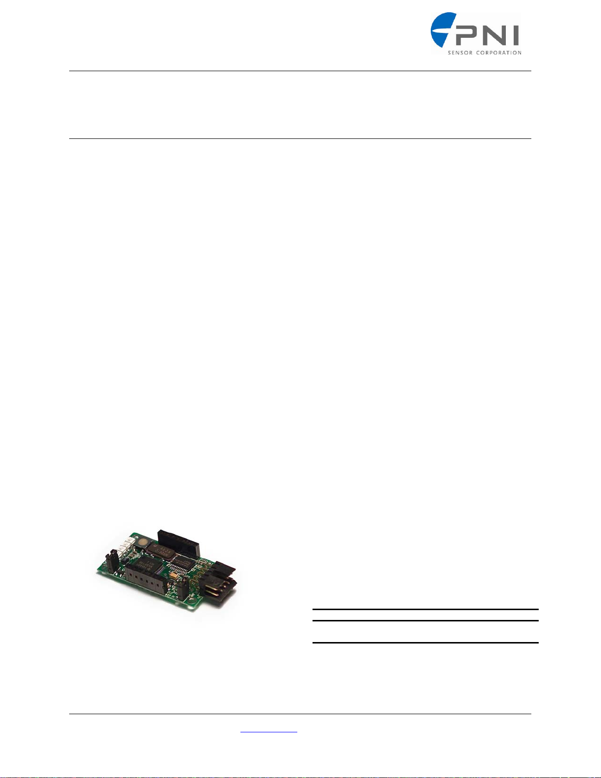
PNI CommBoard (RS-232, RS-485)
General Description
The CommBoard is a communication interface
designed to connect the MicroMag and V2Xe
modules to a host system that uses a standard
serial interface, such as a PC. It is typically used
as a prototyping and evaluation tool for PNI’s
line of compass and magnetometer modules. The
PNI CommBoard is also used for production
when the host system requires a higher level
serial protocol to interface to the PNI sensor
modules. The first version of the PNI
CommBoard features a user selectable RS-232
or RS-485 interface to the host system. The
CommBoard developer kit comes with software
for the PC that has a graphical user interface
(GUI) to control every aspect of the
CommBoard and any PNI module that is
attached to it.
In the future, different interfaces may be made
available as customer needs are identified.
Please contact PNI for support with your custom
interface high-volume opportunity
.
Features
Small size: 53 x 25 x 11 mm
RS-232 and RS-485 interfaces for
connection with PCs or other serial interface
systems
GUI control software available from PNI,
either as part of the developer kit or via the
web
Built-in support for PNI MicroMag and
V2Xe sensor modules, as well as several
future products
Voltage regulator converts 6 - 12 VDC to 3
VDC for power to the sensor modules
Minimal code changes required when
upgrading from PNI’s TCM-2 line of tilt
compensated magnetometer compass
modules
Applications
Fast compass and magnetometer prototyping
New product evaluation
Education, school projects
Any legacy compass application that has an
RS-232 interface but needs the performance
of new PNI products
Production applications where standards
based protocols are preferred over SPI.
Ordering Information
Name Part # Package
CommBoard Kit
(with cable & software)
Table 1
PNI Sensor Corporation 133 Aviation Blvd., suite 101, Santa Rosa, CA 95403-1084 USA
Phone: (707) 566-2260, Fax: (707) 566-2261, Web: www.pnicorp.com Page 1 of 42
90009 Each
Page 2

This page left intentionally blank
PNI Corporation 133 Aviation Blvd., Suite 101, Santa Rosa, CA 95403-1084 USA;, Fax: (707) 566-2261
For the most current specifications, please visit our website at: www.pnicorp.com
Page 2 of 42
Page 3

SPECIFICATIONS
CAUTION:
Stresses beyond those listed under Table 2: Absolute Maximum Ratings may cause
permanent damage to the device. These are stress ratings only. Functional operation of
the device at these or any other conditions beyond those indicated in the operational
sections of the specifications is not implied. Exposure to absolute maximum rating
conditions for extended periods may affect device reliability.
Table 2: Absolute Maximum Ratings
Symbol Parameter Minimum Maximum
VDD DC supply voltage -0.3 VDC 16 VDC
VIN
T
Storage Temperature -40°C 85°C
STRG
Input pin voltage
(CTS, RxD) to ground
Input pin voltage
(TxD, RTS) to ground
Input pin voltage
(D+, D-) to ground
CommBoard
Specifications
-25 VDC 25 VDC
-13.2 VDC 13.2 VDC
-13.2 VDC 13.2 VDC
PNI Corporation 133 Aviation Blvd., Suite 101, Santa Rosa, CA 95403-1084 USA;, Fax: (707) 566-2261
For the most current specifications, please visit our website at: www.pnicorp.com
Page 3 of 42
Page 4

Table 3: Characteristics
Parameter Minimum Maximum Typical
Operating Characteristics
Current – standby
(Low power mode, no module loaded)
LPM0a 14.4 mA RMS
b
LPM1
7.0 mA RMS
LPM2c 5.4 mA RMS
RS-232 Receiver Inputs (CTS, RxD)
Input threshold low 0.6 VDC
Input threshold high 2.0 VDC
RS-232 Transmitter Output (TxD)
Output Voltage Swing
(both transmitter outputs loaded with 3KΩ to GND)
Output resistance
= V+ = V- =0, output = 2 V)
(V
CC
Output short circuit current
(Output = GND)
RS-485 Transceiver Signals (D-, D+)
Input differential threshold -200 mVDC -50 mVDC
Differential output voltage
(R = 27 Ω)
Change in magnitude of differential output voltage for
complementary output states
(R = 27Ω or 50Ω)
Common mode output voltage
(R = 27Ω or 50 Ω)
Change in magnitude of common mode output
voltage for complementary output states
(R = 27Ω or 50 Ω)
Output sort-circuit current
(V
or VZ = +12 V to – 7 V)
Y
a. The unit is in normal operating mode with the LEDs enabled.
b. The unit is in normal operating mode with the LEDs disabled.
c. The unit is in a Sleep mode and will need to be awakened via the CTS (Wake Up) line.
CommBoard
Specifications
±5 VDC ±5.4 VDC
300Ω 10MΩ
±60 mA ±30 mA
1.5 VDC
-0.2 VDC 0.2 VDC
3.0 VDC
0.2 VDC
±250 mA
PNI Corporation 133 Aviation Blvd., Suite 101, Santa Rosa, CA 95403-1084 USA;, Fax: (707) 566-2261
For the most current specifications, please visit our website at: www.pnicorp.com
Page 4 of 42
Page 5

Serial Pin Descriptions
Figure 1: Jumpers and Connectors
CommBoard
Specifications
Table 4: Serial Pin Descriptions (J1)
Pin Name Function
1 TxD RS-232 transmitter output (transmitted data)
2 Reserved RS-232 transmitter output (reserved)
3 n/c not connected
4 RxD RS-232 receiver input (received data)
5 D– RS-485 transceiver signal (inverting RS-485 signal)
6 D+ RS-485 transceiver signal (non-inverting RS-485 signal)
7 n/c not connected
8 GND Ground
9 VCC Supply voltage (5 to 12 VDC)
10 GND Ground
RS-232 and RS-485 Jumper Settings
Table 5: Jumper Configuration
Configuration Mode
JMP1 installeda RS-232
JMP1 removeda RS-485
JMP2 installedb RS-485; 120 Ω line termination
JMP2 removedb RS-485; no line termination
a. The processor only checks the status of JMP1 at power up. IF the position of the jumper
needs to be changed, either cycle the power or press the RESET switch after the change
has been made.
b. JMP2 must only be installed on the last unit of the network. All other units need to have
JMP2 removed for proper RS-485 operation.
PNI Corporation 133 Aviation Blvd., Suite 101, Santa Rosa, CA 95403-1084 USA;, Fax: (707) 566-2261
For the most current specifications, please visit our website at: www.pnicorp.com
Page 5 of 42
Page 6

Serial Pin Descriptions (cont).
CommBoard
Specifications
Table 6: Connector J2
Pin Function I/O Direction
1 SCLK Output
2 MISO Input
3 MOSI Output
4 SSNOT Output
5 DRDY Input
6 SYNC Output
7 GND
8 GIO0 Output low
9 GIO1 Output low
10 GIO2 Output low
11 GIO3 Output low
12 VDD
13 VCC
14 GGND
PNI Corporation 133 Aviation Blvd., Suite 101, Santa Rosa, CA 95403-1084 USA;, Fax: (707) 566-2261
For the most current specifications, please visit our website at: www.pnicorp.com
Page 6 of 42
Page 7

CommBoard
Specifications
Hardware Modes
The CommBoard provides a serial interface to PNI’s sensor modules. Its purpose is to translate a serial
command from a host system into the appropriate SPI command. If the sensor module does not support
the command, it will return the appropriate error code. Otherwise, it will return the associated data. See
the applicable PNI module data sheet for specific information on communication and control using the
SPI interface.
• RS-232 mode uses software handshaking to communicate.
o Xon = ^Q = 0 x 11 (okay to send data)
o Xoff = ^S = 0 x 13 (stop sending data)
• RS-485 mode is only Half-Duplex.
o The Continuous Output (go) command is not allowed since Half-Duplex implies queried
responses only.
o The CommBoard acts as a Slave when the JMP1 is removed.
Example
!FF00$C194.74X-106.00Y-403.00Z98.00:E200*1E
!DdSs${data}*<dcs><es>
Table 7: Hardware Modes
! RS-485 data delimiter
Dd Destination address
Ss Source address
$ Start data delimiter
{data} Selected data output
* End data delimiter
<dcs> Checksum
<es> End of message based on eol variable <cr> or <lf> or <cr><lf>
NOTE:
The query and response format must match. All examples in this manual show the query and response
of the RS-232 mode. When using RS-485 just add the RS-485 data delimiter, destination address,
source address and checksum, to the examples shown.
Checksum
The CommBoard uses a XOR checksum method from the beginning of the string up to, but not
including, the end data delimiter (“*”). Examples:
RS-232 RS-485
Sent Command
Reply
PNI Corporation 133 Aviation Blvd., Suite 101, Santa Rosa, CA 95403-1084 USA;, Fax: (707) 566-2261
For the most current specifications, please visit our website at: www.pnicorp.com
id? (no checksum required) !00ff$id?*37 $id=3*27
!00ff$id?*06
Page 7 of 42
Page 8

Standard Data Output Modes
PNI Standard Output Mode (sdo=t)
The PNI Standard Output Mode may be configured to provide all sensor data availability, or only
the data you require.
EXAMPLE:
$C194.74X-106.00Y-403.00Z98.00:E200*1E
${data}*<dcs><es>
Table 8: Standard Output Modes
$ Start data delimiter
{data} Selected data output
* End data delimiter
<dcs> Checksum up to but not including “*”
<es> End of message based on eol variable <cr> or <lf> or <cr><lf>
NMEA Output Mode (National Marine Electronics Association ) (sdo=n)
The NMEA Output mode conforms to the 0183 specification. In this mode, only compass
heading information is available.
EXAMPLE:
$HCHDM,71.33,M*2F
$HC<sid>,{data},<dt>*<dcs><es>
CommBoard
Specifications
Table 9: NMEA Output Modes
$ Start data delimiter
HC Heading compass (magnetic), Talker ID
<sid> Heading magnetic = HDM, heading true = HDT, Sentence ID
71.33 Heading degrees
<dt> Data type M = magnetic, T = true
* End data delimiter
<dcs> Checksum
<es> End of message based on eol variable <cr> or <lf> or <cr><lf>
PNI Corporation 133 Aviation Blvd., Suite 101, Santa Rosa, CA 95403-1084 USA;, Fax: (707) 566-2261
For the most current specifications, please visit our website at: www.pnicorp.com
Page 8 of 42
Page 9

Raw Output Mode (sdo=r)
The Raw Output mode allows for the output of the raw, uncorrected data for any or all of the
required sensors. The Raw Output Mode is the only mode where Z-Axis is active.
EXAMPLE:
$raw,X53Y-420Z0*6E
$raw,{data}*<dcs><es>
Table 10: Raw Output Modes
$ Start data delimiter
{data} Selected data output
* End data delimiter
<dcs> Checksum
<es> End of message based on eol variable <cr> or <lf> or <cr><lf>
NOTE: For modules with a Z-axis when used in other modes than raw, Z-axis is turned off and module
is run as a Z-axis system since no tilt compensation is being done.
PNI Corporation 133 Aviation Blvd., Suite 101, Santa Rosa, CA 95403-1084 USA;, Fax: (707) 566-2261
For the most current specifications, please visit our website at: www.pnicorp.com
Page 9 of 42
Page 10

Command Line Interface
CommBoard
Command Line Interface
The Command Line interface allows you to use a simple terminal program to communicate with the
CommBoard. The Command Line interface also allows applications written in any language, including
Assembly, Basic, or C to communicate with the CommBoard via the RS-232 or RS-485.
Command Sequence
The sequence of command line events is:
1. Type in the command on the terminal program:
2. The module processes the command.
3. A reply is sent back to you.
a. If no error
b. If error
$cmdreply*<dcs><es>
$cmdreply:Exxx*<dcs><es>
cmd?<es>
Table 11: Command Notation Table
Command Symbol
? Indicated query only command or variable
= Indicates assign only command or variable
<aq>
<es>
$ Start of checksum data
! RS-485 address follows
:
* End of checksum data
<dcs> Checksum
<er> Start of data
n n Usually a lower case ‘n’ will represent a digit (0-9)
n.n n.n Represents a decimal value (positive or negative)
x x Usually a lower case ‘x’ will represent a hex digit (0-F)
xx xx Represents a Uint8
xxxx xxxx Represents a Uint16
xxxxxxxx xxxxxxxx Represents a Uint32
a. XOR checksum method.
Response Symbol
Description
Use ? for query or =<val> for assign
Ending sequence <cr> or <lf> or <cr><lf>
If error occurs; :Ennn
PNI Corporation 133 Aviation Blvd., Suite 101, Santa Rosa, CA 95403-1084 USA;, Fax: (707) 566-2261
For the most current specifications, please visit our website at: www.pnicorp.com
Page 10 of 42
Page 11

Example Command Notation
m<aq><es>
This will be interpreted as a query: em?<es>
This will be interpreted as assignment: em=<val><es>
Example Response Notation
$em=<val>*<dcs><er>
Ending Sequence
Command Line Interface
CommBoard
The CommBoard will accept either
EOL (end of line) Response
The CommBoard will send a response to you in the chosen EOL format.
If (eol=cr) Send (“\r”)
If (eol=lf) Send (“\n”)
If (eol=crlf) Send (“\r\n”)
<cr> or <lf> or <cr><lf> as an end of line (eol) indicator.
PNI Corporation 133 Aviation Blvd., Suite 101, Santa Rosa, CA 95403-1084 USA;, Fax: (707) 566-2261
For the most current specifications, please visit our website at: www.pnicorp.com
Page 11 of 42
Page 12

Command Line Interface
CommBoard
Error Codes
Error codes are a bitmap to the error that has occurred and are sent when an error condition has occurred.
Example
$C194.74X-106.00Y-403.00Z98.00:E200*1E
$Cnnn.nnXnnn.nnYnnn.nnZnnn.nn:Exxx*<dcs><er>
Exxx: “xxx” are hex values between 0 - F.
The built-in error command to parse error messages, error ffff<cr><lf>, will list the error codes.
Table 12: Error Codes
Code Description
E800 EEPROM1 error a
E400 EEPROM2 error a
E200 Module not calibratedb
E100 Module not capable
E080 Internal error
E040 Command parameter invalid
E020 Command/data mode conflict
E010 Command invalid or unavailable
E008 Module not found
E004 Magnetometer out of range
E002 Inclinometer out of range
E001 Magnetic distortion alarm
a. Indicates a possible problem with the unit. Please contact PNI
Corporation
A compass heading of –1.00 will be output when the module is not
b.
calibrated. $c-1.00:E200
Indicates that the magnetic field has changed significantly since
c.
the last calibration. See the specific module data sheet for the
parameter range
.
PNI Corporation 133 Aviation Blvd., Suite 101, Santa Rosa, CA 95403-1084 USA;, Fax: (707) 566-2261
For the most current specifications, please visit our website at: www.pnicorp.com
Page 12 of 42
Page 13

ACTION COMMANDS
factory (Factory Settings Restore)
Restores the CommBoard and modules to the factory default configuration.
Syntax:
Response Format: $factory*<dcs><er>
go (Continuous Output)
Instructs the CommBoard to enter continuous mode. The CommBoard will begin sampling
sensors at the rate specified by the Polling Frequency (pollfreq) command.
Syntax:
Response Format: $(select data)*<dcs><er>
Notes: Stopped using the h command
h (Halt Continuous Output)
Instructs the CommBoard to exit the continuous output mode.
Syntax:
h if halt = e
Response Format: $h*<dcs><er>
help or ? (Help Menu)
Instructs the CommBoard to display the Help menu.
Syntax:
Response Format: Menu Data
factory<es>
go<es>
h<es> if halt = d see halt command
help<es> or ?<es>
CommBoard
Action Commands
PNI Corporation 133 Aviation Blvd., Suite 101, Santa Rosa, CA 95403-1084 USA;, Fax: (707) 566-2261
For the most current specifications, please visit our website at: www.pnicorp.com
Page 13 of 42
Page 14

id? (Module Identification)
Displays the module type. IF the MicroMag responds with either 01 or 02, contact PNI
Corporation as there could possibly be a damaged or unconnected sensor.
Syntax:
Response Format: $id=xx*<dcs><er>
Valid Values: xx = 00 None
info? (Module Information)
Displays the CommBoard software version, module type, and module software version, if
applicable.
Syntax:
Response Format: $info,PNI-commboard Vnnn*<dcs> CommBoard
info, {module info}*<dcs> Module
id?<es>
xx = 01 MicroMag (X sensor only)
xx = 02 MicroMag (Y sensor only)
xx = 03 MicroMag (X and Y sensors)
xx = 07 MicroMag (X, Y and Z sensors)
xx = 10 V2Xe
info?<es>
CommBoard
Action Commands
PNI Corporation 133 Aviation Blvd., Suite 101, Santa Rosa, CA 95403-1084 USA;, Fax: (707) 566-2261
For the most current specifications, please visit our website at: www.pnicorp.com
Page 14 of 42
Page 15

QUERY COMMANDS
Q
c? (Compass Update)
Retrieves the compass heading. Based upon the setting for the Data Output Forma (sdo)
command and the Compass Units (uc) command. Refer to “pollfreq” on page 21.
Note: For modules that do not have an onboard processor (for example, the MicroMag), the
CommBoard will calculate and output this data
Syntax:
Response Format: $c{hdg}*<dcs><er>
Valid Values: hdg = 0 to 359.99 if uc = d
hdg = 0 to 6399 if uc = m
error x (Error Code List)
Retrieves a description of the error code entered from the CommBoard. Refer to “Error Codes”
on page 11.
Syntax:
error ffff<ex>
Response Format: $error x: (description) *<dcs><er>
Valid Values: x the error number following the “E” in the response string
m? (Magnetometer Update)
Retrieves the corrected X, Y, and Z axis magnetometer data. Corrected data is that which isused
to calculate heading. The Z sensor output is not available on all modules. Refer to the specific
module data sheet for more information.
Note: For modules that do not have an onboard processor (for example, the MicroMag), the
CommBoard will calculate and output this data
Syntax:
Response Format: $Xn.nYn.NZn.n*<dcs><er>
Valid Values:
c?<es>
error x<es>
ffff lists all error codes
m?<es>
xn.n
CommBoard
uery Commands
PNI Corporation 133 Aviation Blvd., Suite 101, Santa Rosa, CA 95403-1084 USA;, Fax: (707) 566-2261
For the most current specifications, please visit our website at: www.pnicorp.com
Page 15 of 42
Page 16

s? (Single Sample Update)
Q
Retrieves the user selected calibration information. Based upon the settings of the various
Configuration commands
Note: For modules that do not have an onboard processor (for example, the MicroMag), the
CommBoard will calculate and output this data
Syntax:
s?<es>
Response Format: ${selectedData}*<dcs><er>
Valid Values: selectedData varies according to user settings
sr? (Single Raw Sample Update)
Retrieves the raw data (uncorrected ASIC output) for the sensors selected. For example, X, Y,
and Z axis magnetometers. The Z sensor output is not available on all modules. Refer to the specific module data sheet for more information
Syntax:
sr?<es>
Response Format: ${selectedRawData}*<dcs><er>
Valid Values: selectedRawData varies according to user settings
t? (Temperature Update)
Retrieves the temperature value. Outputs are based on the setting of the Temperature Units (ut)
command. The temperature output is not available in all modules. Refer to the specific data sheet
for more information.
Syntax:
Response Format: $Tn.n*<dcs><er>
Valid Values:
t?<es>
$Tn.n the calibrated temperature sensor output
CommBoard
uery Commands
PNI Corporation 133 Aviation Blvd., Suite 101, Santa Rosa, CA 95403-1084 USA;, Fax: (707) 566-2261
For the most current specifications, please visit our website at: www.pnicorp.com
Page 16 of 42
Page 17

x? (X Axis Sensor Update)
Q
Retrieves only the corrected X axis magnetometer values used for heading calculation.
Note: For modules that do not have an onboard processor (for example, the MicroMag), the
CommBoard will calculate and output this data
Syntax: x
Response Format: $Xn.n*<dcs><er>
Valid Values: n.n
y? (Y Axis Sensor Update)
Retrieves only the corrected Y axis magnetometer values used for heading calculation.
Note: For modules that do not have an onboard processor (for example, the MicroMag), the
CommBoard will calculate and output this data
Syntax: y
Response Format: $Yn.n*<dcs><er>
Valid Values: n.n
?<es>
?<es>
CommBoard
uery Commands
PNI Corporation 133 Aviation Blvd., Suite 101, Santa Rosa, CA 95403-1084 USA;, Fax: (707) 566-2261
For the most current specifications, please visit our website at: www.pnicorp.com
Page 17 of 42
Page 18

CONFIGURATION COMMANDS
g
b (Baud Rate)
Sets the baud rate of the CommBoard
Syntax: b
Response Format: $b={value}*<dcs><er>
Valid Values:
Query Syntax:
ec (Compass Data Enable)
Enables the compass data output
Note: For modules that do not have an onboard processor (for example, the MicroMag), the
CommBoard will calculate and output this data
Syntax: ec
Response Format: $ec={value}*<dcs><er>
Valid Values: e = enabled (default)
d = disabled
Query Syntax:
<aq><es>
Table 13
0 = 300 5 = 9600(default)
1 = 600 6 = 19200
2 = 1200 7 = 38400
3 = 2400 8 = 57600
4 = 4800
b?<es>
<aq><es>
ec?<es>
Confi
uration Commands
CommBoard
PNI Corporation 133 Aviation Blvd., Suite 101, Santa Rosa, CA 95403-1084 USA;, Fax: (707) 566-2261
For the most current specifications, please visit our website at: www.pnicorp.com
Page 18 of 42
Page 19

echo (Echo Characters Enable)
g
Enables character echo, which directs the CommBoard to echo locally typed characters onto the
display
Syntax: echo
Response Format: $echo={value}*<dcs><er>
Valid Values: e = enabled
d = disabled (default)
Query Syntax:
echo?<es>
em (Magnetometer Data Enable)
Enables all of the magnetometer data output. For example, em=e will set ex=e, ey=e and ez=e.
Note: If any axis is disabled after
in raw mode.
Syntax: em
<aq><es>
Response Format: $em={value}*<dcs><er>
Valid Values: e = enabled
d = disabled (default)
Query Syntax:
em?<es>
eol (End of Line Enable)
Sets the type of end of line output
Syntax: eol
Response Format: $eol={value}*<dcs><er>
Valid Values: cr = output cr after line
lr = output lr after line
crlf = output crlf after line (default)
Query Syntax: eol
<aq><es>
?<es>
Confi
<aq><es>
em=e, em? will still respond with em=e. Z-axis is only active
CommBoard
uration Commands
PNI Corporation 133 Aviation Blvd., Suite 101, Santa Rosa, CA 95403-1084 USA;, Fax: (707) 566-2261
For the most current specifications, please visit our website at: www.pnicorp.com
Page 19 of 42
Page 20

et (Temperature Data Enable)
Enables the temperature data output. Temperature output is not available on all modules. Refer
to the specific module data sheet for more information.
Syntax: et
Response Format: $et={value}*<dcs><er>
Valid Values: e = enabled
d = disabled (default)
Query Syntax:
et?<es>
ex (X Axis Data Enable)
Enables the X-axis data output.
Syntax:
ex<aq><es>
Response Format: $ex={value}*<dcs><er>
Valid Values: e = enabled
d = disabled (default)
Query Syntax:
ex?<es>
ey (Y Axis Data Enable)
Enables the Y-axis data output.
Syntax:
Response Format: $ey={value}*<dcs><er>
Valid Values: e = enabled
d = disabled (default)
Query Syntax:
ey<aq><es>
ey?<es>
<aq><es>
Configuration Commands
CommBoard
PNI Corporation 133 Aviation Blvd., Suite 101, Santa Rosa, CA 95403-1084 USA;, Fax: (707) 566-2261
For the most current specifications, please visit our website at: www.pnicorp.com
Page 20 of 42
Page 21

ez (Z Axis Data Enable)
Enables the Z-axis data output. The Z sensor output is not available on all modules. Refer to the
specific module data sheet for more information. Z-axis is only active in raw mode.
Syntax:
ez<aq><es>
Response Format: $ez={value}*<dcs><er>
Valid Values: e = enabled
d = disabled (default)
Query Syntax:
ez?<es>
halt (Single Character Halt Enable)
Enables sending a single Halt (h) command to cancel the Continous Output (go) mode.
Syntax: halt
<aq><es>
Response Format: $halt={value}*<dcs><er>
Valid Values: e enabled; h (default)
d disabled; h<es>
Query Syntax:
halt?<es>
lpm (Low Power Mode)
Selects the low power mode for the CommBoard. Once set to lpm=2, the CommBoard will
“wake” from ultra low power and go into
interface.
Syntax:
Response Format: $lpm={value}*<dcs><er>
Valid Values: 0 no conversion (default)
Query Syntax:
Table 3 on page 4 lists the current draw at the different lpm levels.
lpm<aq><es>
1 LEDs off
2 ultra low power
lpm?<es>
Configuration Commands
CommBoard
lpm=0 when it receives a character over the RS-232
PNI Corporation 133 Aviation Blvd., Suite 101, Santa Rosa, CA 95403-1084 USA;, Fax: (707) 566-2261
For the most current specifications, please visit our website at: www.pnicorp.com
Page 21 of 42
Page 22

pollfreq (Polling Frequency)
Sets the sample polling frequency of the Continuous Output (go) command.
Syntax: pollfreq
Response Format: $pollfreq=nn*<dcs><er>
Valid Values: nn 0 = 1 sample/2 seconds
1 – 16 = value in Hz (default is 8)
Query Syntax:
pollfreq?<es>
rs485 (RS-485 Slave Address)
Sets the slave address for the CommBoard in RS-485 mode.
Syntax: rs485
Response Format: $rs485=xx*<dcs><er>
Valid Values: xx 00 to 7F (default is 00)
Query Syntax:
rs485?<es>
sdo (Data Output Format)
Sets the data output format to PNI standard, NMEA, or RAW. Refer to “Standard Output
Modes” on page 8 for more information.
Syntax: sdo
Response Format: $sdo={value}*<dcs><er>
Valid Values: t PNI standard format (default)
n NMEA 0183 compatible format
r raw output format (uncorrected from sensors)
Query Syntax:
sdo?<es>
<aq><es>
<aq><es>
<aq><es>
Configuration Commands
CommBoard
PNI Corporation 133 Aviation Blvd., Suite 101, Santa Rosa, CA 95403-1084 USA;, Fax: (707) 566-2261
For the most current specifications, please visit our website at: www.pnicorp.com
Page 22 of 42
Page 23

uc (Compass Units)
g
Sets the compass output to either degrees or mils.
Note: For modules that do not have an onboard processor (for example, the MicroMag), the
CommBoard will calculate and output this data
Syntax: uc
Response Format: $uc={value}*<dcs><er>
Valid Values: d degrees (default)
m mils
Query Syntax:
ut (Temperature Units)
Sets the temperature units to either Fahrenheit or Celsius. Temperature output is not available on
all modules. Refer to the specific module data sheet for more information.
Syntax: ut
Response Format: $ut={value}*<dcs><er>
Valid Values: f Fahrenheit (default)
c Celsius
Query Syntax:
<aq><es>
uc?<es>
<aq><es>
ut?<es>
Confi
uration Commands
CommBoard
PNI Corporation 133 Aviation Blvd., Suite 101, Santa Rosa, CA 95403-1084 USA;, Fax: (707) 566-2261
For the most current specifications, please visit our website at: www.pnicorp.com
Page 23 of 42
Page 24

MODULE COMMANDS
cc (Clear Calibration Data)
Clears the previous calibration information. Refer to the specific module data sheet for more
information.
Note: For modules that do not have an onboard processor (for example, the MicroMag), the
CommBoard will calculate and output this data
Syntax:
Response Format: $cc*<dcs><er>
damping (Digital Damping Enable)
Enables digital damping on the compass heading output. Refer to specific module data sheet for
more information.
Note: For modules that do not have an onboard processor (for example, the MicroMag), the
CommBoard will calculate and output this data
Syntax:
Response Format: $damping ={value}*<dcs><er>
Valid Values: d disabled (default)
e enabled
Query Syntax:
cc<es>
damping<aq><es>
damping?<es>
CommBoard
Module Commands
PNI Corporation 133 Aviation Blvd., Suite 101, Santa Rosa, CA 95403-1084 USA;, Fax: (707) 566-2261
For the most current specifications, please visit our website at: www.pnicorp.com
Page 24 of 42
Page 25

dampsize (Digital Damping Sample Size)
Sets the value for the digital damping of the compass heading output. Refer to specific module
data sheet for more information.
Note: For modules that do not have an onboard processor (for example, the MicroMag), the
CommBoard will calculate and output this data
Syntax:
dampsize<aq><es>
Response Format: $dampsize=nn*<dcs><er>
Valid Values: nn 1 – 8 for the MicorMag (1 is the default)
1 – 8 for the V2Xe (1 is the default)
Query Syntax:
dampsize?<es>
mag_dec (Declination Value)
Sets the declination offset for a reading of True North. Based on the setting of the Compass Units
(uc) command. Positive declination is easterly declination and negative is westerly declination.
This is not applied until True North is set to true.
Declination, also called magnetic variation, is the difference between true and magnetic north,
relative to a point on the earth. It is measured in degrees east or west of true north. Correcting for
declination is accomplished by storing the correct declination angle, and then changing the heading reference from magnetic north to true north. Declination angles vary throughout the world,
and change very slowly over time. For the greatest possible accuracy, go to the National Geophysical Data Center web page below to get the declination angle based on your latitude and longitude: http://www.ngdc.noaa.gov/cgi-bin/seg/gmag/fldsnth1.pl
Note: For modules that do not have an onboard processor (for example, the MicroMag), the
CommBoard will calculate and output this data
Syntax:
Response Format: $mag_dec=nnn*<dcs><er>
Valid Values: nnn = ±180 If
nnn = ±3200 If
Query Syntax:
mag_dec<aq><es>
mag_dec?<es>
CommBoard
Module Commands
uc = d, then mag_dec is in degrees (default is 0)
uc = m, then mag_dec is in mils (default is 0)
PNI Corporation 133 Aviation Blvd., Suite 101, Santa Rosa, CA 95403-1084 USA;, Fax: (707) 566-2261
For the most current specifications, please visit our website at: www.pnicorp.com
Page 25 of 42
Page 26

mpcal (Multi-Polled Calibration Enable)
Enables the multi-polled calibration.
Note: For modules that do not have an onboard processor (for example, the MicroMag), the
CommBoard will calculate and output this data
2-Axis Compass Calibration using the CommBoard
Calibration is the process used with PNI sensor technology to separate the earth’s magnetic field
from magnetic field distortions. Magnetic field distortions are created by the environment into
which the sensors are mounted. By implementing a simple calibration routine with the sensors in
a fixed position within the host system, the maximum and minimum strength fields can be determined and then used to correct the sensor output for the distortions present. A calibration should
be performed under the following conditions:
• when the unit is first installed into a host system.
• when the unit is moved.
• when the unit indicates that it is in need of a calibration.
Follow the steps below to perform a calibration.
1. Place the unit to be calibrated into the host system.
2. Set the unit at its intended operating position in as level of a position as possible.
3. Sent the Multi-Polled Calibration Enable (mpcal=e) command. This enables the calibration
routine.
4. Send the Go Command
5. Rotate the unit through two 360 degree circles while maintaining a level position. The
rotations should be no faster than 30 seconds each to achieve the highest possible accuracy.
6. Send the h command
7. Send the Multi-Polled Calibration Disable (mpcal=d) command. This disables the calibration
routine.
8. Send the Save Settings (save) command to save the calibration information to the
CommBoard and the attached module, where applicable.
Syntax:
Response Format: $mpcal{value}*<dcs><er>
Valid Values: d disabled (default)
e enabled
Query Syntax:
mpcal<es>
mpcal?<es>
CommBoard
Module Commands
PNI Corporation 133 Aviation Blvd., Suite 101, Santa Rosa, CA 95403-1084 USA;, Fax: (707) 566-2261
For the most current specifications, please visit our website at: www.pnicorp.com
Page 26 of 42
Page 27

ps (ASIC Period Select)
Sets the value for the ASIC period select. The lowest setting (/32) will provide the fastest
response, but the lowest resolution. The highest setting will provide the slowest response, but the
highest resolution. Refer to specific module data sheet for more response times and maximum
setting allowed.
Syntax:
Response Format: $ps=n*<dcs><er>
Syntax: n = =0 =/32
=1 =/64
=2 =/128
=3 =/256
=4 =/512 (default)
=5 =/1024
=6 =/2048
=7 =/4096
Query Syntax:
save (Save Settings)
Saves the configuration parameters to the CommBoard and attached module (where applicable).
Also used to save calibration coefficients to the CommBoard and attached module (where
applicable)
Syntax:
Response Format: $save*<dcs><er>
ps<aq><es>
ps?<es>
save<aq><es>
CommBoard
Module Commands
PNI Corporation 133 Aviation Blvd., Suite 101, Santa Rosa, CA 95403-1084 USA;, Fax: (707) 566-2261
For the most current specifications, please visit our website at: www.pnicorp.com
Page 27 of 42
Page 28

sn (North Mode)
Used to set either True or Magnetic North. If the value is set to true, then declination is applied to
get the True North heading.
Note: For modules that do not have an onboard processor (for example, the MicroMag), the
CommBoard will calculate and output this data
Syntax:
Response Format: $sn={value}*<dcs><er>
Valid Values: m magnetic (default)
t true
Query Syntax:
be (Big Endian)
Used to set the endianism of multi-byte parameters (Float32, Uint32, SInt32). If enabled, all
parameters communicated between the module and the CommBoard are assumed to be big
endian, if disabled they are assumed to be little endian
Note: For modules that do not have an onboard processor (for example, the MicroMag), the
CommBoard will calculate and output this data
Syntax:
Response Format: $be={value}*<dcs><er>
Valid Values: e enabled (default)
d disabled
Query Syntax:
sn<aq><es>
sn?<es>
be<aq><es>
be?<es>
CommBoard
Module Commands
PNI Corporation 133 Aviation Blvd., Suite 101, Santa Rosa, CA 95403-1084 USA;, Fax: (707) 566-2261
For the most current specifications, please visit our website at: www.pnicorp.com
Page 28 of 42
Page 29

SPI Interface to Sensor Module
SPI INTERFACE TO SENSOR MODULE
Table 14: SPI Pin Descriptions
Pin Name Description
1 SCLK Serial clock output for the SPI port
2 MISO Serial data input. Master In Slave Out
3 MOSI Serial data output. Master Out Slave In
4 SSNOT Active low chip select for SPI port
5 DRDY Data ready input (not supported by V2Xe module)
6 SYNC Sync output
7 GND Ground
8 GIO0 Reserved I/O
9 GIO1 Reserved I/O
10 GIO2 Reserved I/O
11 GIO3 Reserved I/O
12 VDD Supply voltage, 3 VDC regulated
13 VCC Unregulated CommBoard input supply voltage
14 GND Ground
SPI Port Pin Descriptions
MOSI – Master Out Slave In
The data sent from the CommBoard. Data is transferred most significant bit first. The MOSI line will
accept data once the SPI is enabled by taking SSNOT low. Valid data must be presented at least 100 nS
before the rising edge of the clock, and remain valid for 100 nS after the edge. New data may be presented
to the MOSI pin on the falling edge of SCLK.
CommBoard
SSNOT - Slave Select Line
Selects the module as the operating slave device. The SSNOT line must be low prior to data transfer and
must stay low during the entire transfer. Once the command byte is received by the module, and the module
begins to execute the command, the SSNOT line can be deselected until the nex t SPI transfer.
SCLK – Serial Clock
Used to synchronize both the data in and out through the MISO and MOSI lines. SCLK is generated by the
CommBoard. SCLK should be 1 MHz or less. The CommBoard is configured to run as a master device,
making it an output. One byte of data is exchanged over eight clock cycles. Data is captured by the
CommBoard on the rising edge of SCLK. Data is shifted out and presented to the module on the MOSI pin
on the falling edge of SCLK.
MISO – Master In Slave Out
The data sent from the module to the CommBoard. Data is transferred most significant bit first. The MISO
line is placed in a high impedance state if the slave is not selected (SSNOT = 1).
PNI Corporation 133 Aviation Blvd., Suite 101, Santa Rosa, CA 95403-1084 USA;, Fax: (707) 566-2261
For the most current specifications, please visit our website at: www.pnicorp.com
Page 29 of 42
Page 30

SPI Interface to Sensor Module
CommBoard
SPI Hardware Handshaking Line Descriptions
SYNC
SYNC is usually low. SYNC must be toggled from low-high-low. This is the SPI reset. This line is used to reset
the SPI slave when communications get out of synchronization. SYNC is normally used during the module
startup.
DRDY – Data Ready
The module returns DRDY. DRDY is low after a SYNC. Once a command has been received and the data is read,
DRDY goes high. This is only used with modules that do not have processor.
NOTE:
See the applicable PNI module data sheet for specific information on communication and control using
the SPI interface
PNI Corporation 133 Aviation Blvd., Suite 101, Santa Rosa, CA 95403-1084 USA;, Fax: (707) 566-2261
For the most current specifications, please visit our website at: www.pnicorp.com
Page 30 of 42
Page 31

PNI CommBoard (RS-232 and RS-485)
LED Status Indicators
1. A live indicator, toggling every ½ second.
2. Not used.
3. Not used.
4. On during transition, off when not in transition.
SPI Interface to Sensor Module
CommBoard
Figure 2: CommBoard Status Indicators
PNI Corporation 133 Aviation Blvd., Suite 101, Santa Rosa, CA 95403-1084 USA;, Fax: (707) 566-2261
For the most current specifications, please visit our website at: www.pnicorp.com
Page 31 of 42
Page 32

Communication Block Diagram
SPI Interface to Sensor Module
CommBoard
Figure 3: Block Diagram
PNI Corporation 133 Aviation Blvd., Suite 101, Santa Rosa, CA 95403-1084 USA;, Fax: (707) 566-2261
For the most current specifications, please visit our website at: www.pnicorp.com
Page 32 of 42
Page 33

Assembly Views
Figure 4: Side Views
SPI Interface to Sensor Module
CommBoard
Figure 5: Top View
PNI Corporation 133 Aviation Blvd., Suite 101, Santa Rosa, CA 95403-1084 USA;, Fax: (707) 566-2261
For the most current specifications, please visit our website at: www.pnicorp.com
Page 33 of 42
Page 34

SPI Interface to Sensor Module
Interchangeable Sensor Module
Unless otherwise stated:
• This document pertains to PNI Corporation part number 11867.
• All units are in metric, millimeters.
• Tolerances are ± 0.1 mm.
• Table 4 page 5 provides pinout definitions for connector J1.
• Serial Pin Descriptions (cont).
• Table 6 on page 6 provides pinout definitions for connector J2.
• The alignment arrows in Figure 6 are defined as pointing in the forward direction.
CAUTION
During installation, ensure that the white silk-screened arrows on both the stacked board and the
CommBoard are pointing towards CommBoard LEDs. Do not misalign or plug the stacked board
into the 7-pin headers backwards. Refer to
Figure 6 and to Figure 7.
CommBoard
PNI Corporation 133 Aviation Blvd., Suite 101, Santa Rosa, CA 95403-1084 USA;, Fax: (707) 566-2261
For the most current specifications, please visit our website at: www.pnicorp.com
Page 34 of 42
Page 35

Figure 6: CommBoard with Module Plugged-In
SPI Interface to Sensor Module
CommBoard
Figure 7: CommBoard with Interchangeable Sensor Module
Item 1, CommBoard
Item 2, Interchangeable Sensor Module
PNI Corporation 133 Aviation B x: (707) 566-2261
For the most current specifications, please visit our website at: www.pnicorp.com
lvd., Suite 101, Santa Rosa, CA 95403-1084 USA;, Fa
Page 35 of 42
Page 36

SPI Interface to Sensor Module
Figure 8: Assembled CommBoard
Dual In-Line and DB9 Connectors
Unless otherwise specified:
1. All units are in standard U.S. inches.
2. Cable assembly specifications provided in Table 15.
3. The pin descriptions for the DB9 female connector are provided in Table 16.
4. The pin descriptions for the Dual In-Line connector are provided in Table 17.
Table 15: Cable Assembly, refer to Callouts on Figure 9
CommBoard
Item Number
1 10357 10 conductor 24 AWG stranded (7 x 32) Belden 9540
2 11772 Crimp housing FCI 65846-010
3 11710 Strap battery 9 VDC I-style 4” lead Keystone 2238
4 11712 D-SUB 9 connector, female JIC DB-09S-UL
5 11711 Overmold, U-shaped JIC HD-09MTL-V
6 11773 Connector crimps FCI 482510-000
PNI Part Number
Description Approved Vendor
Vendor Part Number
Figure 9: Cable Assembly
PNI Corporation 133 Aviation Blvd., Suite 101, Santa Rosa, CA 95403-1084 USA;, Fax: (707) 566-2261
For the most current specifications, please visit our website at: www.pnicorp.com
Page 36 of 42
Page 37

Table 16: DB9 Connector Pin Descriptions. Refer to Figure 10
Pin Wire Description
1 not connected
2 Yellow TxD (RS-232)
3 Blue RxD (RS-232)
4 not connected
5 Green GND
6 not connected
7 White CTS
8 not connected
9 not connected
SPI Interface to Sensor Module
CommBoard
Figure 10: DB9 Close-up
PNI Corporation 133 Aviation Blvd., Suite 101, Santa Rosa, CA 95403-1084 USA;, Fax: (707) 566-2261
For the most current specifications, please visit our website at: www.pnicorp.com
Page 37 of 42
Page 38

Table 17: Dual In-Line Pin Descriptions. Refer to Figure 11.
Pin Wire Description
1 Yellow TxD (RS-232)
2 not connected
3 White or Orange CTS
4 Blue or Brown RxD (RS-232)
5 not connected
6 not connected
7 not connected
8 Green GND
9 Red Vsupply 5 to 12 VDC
10 Black GND
SPI Interface to Sensor Module
CommBoard
Figure 11: Dual In-Line Connector
PNI Corporation 133 Aviation Blvd., Suite 101, Santa Rosa, CA 95403-1084 USA;, Fax: (707) 566-2261
For the most current specifications, please visit our website at: www.pnicorp.com
Page 38 of 42
Page 39

CommBoard
Unused Commands
UNUSED COMMANDS
The following commands are part of the CommBoard programming but are not being used by any of the
PNI products currently available for use with the CommBoard.
i? (Inclinometer Update)
Command Type: Query Command
Retrieves the inclinometer values.
Syntax:
Response Format: $Pn.nRn.n=<dcs><er>
Valid Values: P Pitch
R Roll
z? (Z Axis Sensor Update)
Command Type: Query Command
Retrieves only the corrected Z axis magnetometer values. The Z sensor output is not available on
all modules. Refer to the specific module data sheet for more information.
Syntax: z
Response Format: $Zn.n*<dcs><er>
Valid Values: n.n
i?<es>
?<es>
PNI Corporation 133 Aviation Blvd., Suite 101, Santa Rosa, CA 95403-1084 USA;, Fax: (707) 566-2261
For the most current specifications, please visit our website at: www.pnicorp.com
Page 39 of 42
Page 40

ep (Pitch Data Enable)
Command Type: Configuration Command
Enables the pitch data output.
Syntax:
Response Format: $ep={value}*<dcs><er>
Valid Values: e enabled
d disabled (default)
Query Syntax:
er (Roll Data Enable)
Command Type: Configuration Command
Enables the roll data output.
Syntax:
ep<aq><es>
ep?<es>
er<aq><es>
CommBoard
Unused Commands
Response Format: $er={value}*<dcs><er>
Valid Values: e enabled
d disabled (default)
Query Syntax:
er?<es>
PNI Corporation 133 Aviation Blvd., Suite 101, Santa Rosa, CA 95403-1084 USA;, Fax: (707) 566-2261
For the most current specifications, please visit our website at: www.pnicorp.com
Page 40 of 42
Page 41

ui (Inclinometer Units)
Command Type: Configuration Command
Sets the inclinometer units to either degrees or mils.
Syntax:
ui<aq><es>
Response Format: $ui={value}*<dcs><er>
Valid Values: d degrees (default)
m mils
Query Syntax:
ui?<es>
cclip (Inclinometer Clip Value)
Command Type: Module Command
Sets the clipping value for the maximum positive and negative angle of the inclinometer. When
the inclinometer angle exceeds this value, it is clipped to the set value along with an out of range
flag.
Syntax:
cclip<aq><es>
CommBoard
Unused Commands
Response Format: $cclip=nn.n*<dcs><er>
Valid Values: nn.n 0 to maximum tilt value allowed by the module (0 is default)
Query Syntax:
PNI Corporation 133 Aviation Blvd., Suite 101, Santa Rosa, CA 95403-1084 USA;, Fax: (707) 566-2261
For the most current specifications, please visit our website at: www.pnicorp.com
cclip?<es>
Page 41 of 42
Page 42

lc (Last Calibration Score)
Command Type: Module Command
Retrieves the last calibration score. This option is based on the calibration score of the PNI
Corporation’s TCM2 module and is not available on all modules. Refer to the specific module
data sheet for more information.
Syntax:
Response Format: $HnVnMn.n*<dcs><er>
Valid Values: n is equal to the score value.
Hn 0 – 9
Vn 0 – 9
Mn.n >0
lc? <es>
CommBoard
Unused Commands
PNI Corporation 133 Aviation Blvd., Suite 101, Santa Rosa, CA 95403-1084 USA;, Fax: (707) 566-2261
For the most current specifications, please visit our website at: www.pnicorp.com
Page 42 of 42
 Loading...