

Page 1
43346-01 (9•98)
345 Encinal Street
Santa Cruz
CA 95060
T el 1.800.544.4660
www.plantronics.com
Printed in USA
© 1998 Plantronics, Inc.
V ista
™
Universal Modular Amplifier
M12
User's Guide
VISTA cov.eng.mech 9/16/02 5:18 PM Page 30
Page 2
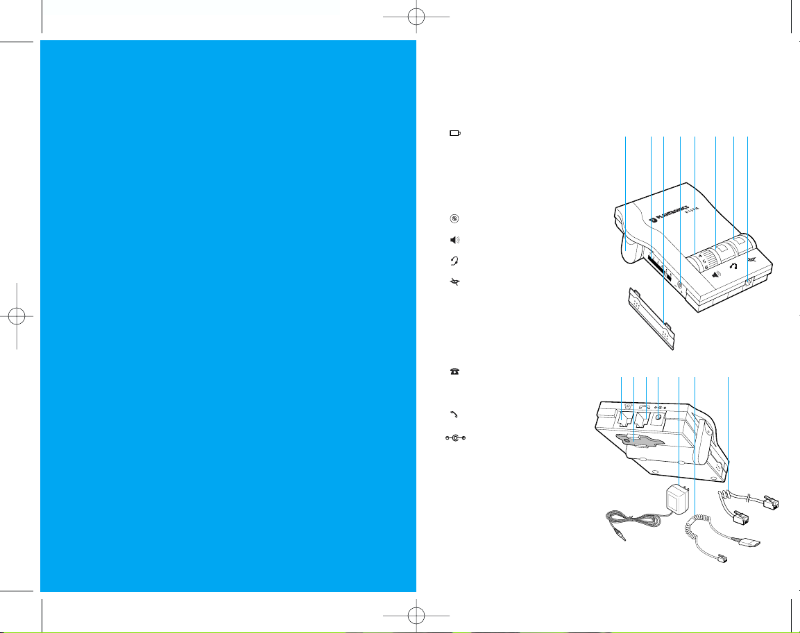
1 Te lephone Jack
2 Screwdriver
3 Handset Jack
4 AC Power Supply Jack
5 AC Power Supply
6 Amplifier to QD Coil Cable
7 Amplifier to Telephone
Coil Cable
Install in 4 easy Steps
Step 1: Install batteries.
Step 2: Attach to phone and headset.
Step 3: Set default settings.
Step 4: Set telephone/amplifier
compatibility switch.
Make a test call.
Learn the basics.
welcome
to the Vista™ Universal
Modular Amplifier
from Plantronics
®
.
PART I
PART II
PART III
The Vista Universal Modular Amplifier adapts your telephone
to a Plantronics headset and provides control of the sound
through your headset. The Vista amplifier has built-in sound
conditioning and protection.
This User Guide will help you install your Vista amplifier and
learn its basic operations.
The Vista amplifier is not designed to work on telephones that have the dial pad in the handset or on
cordless telephones.
english iiiii
1234
5
67
V ista
™
Universal Modular Amplifier
1 Battery Access Door
2 Te lephone/Amplifier
Compatibility Slide Switch
3 Te lephone/Amplifier
Compatibility Slide Switch Cover
4 Outgoing Volume Control
5 Incoming Volume Thumbwheel
6 Headset/Handset Selector
7 Mute
8 Headset Jack
+
_
1
2
345 6
7
8
VISTA.engl.mech 9/16/02 5:12 PM Page ii
Page 3
install
in 4 easy steps
INSTALL BATTERIES
ATTACH TO PHONE AND
HEADSET
SET DEFAULT SETTINGS
SET TELEPHONE/AMPLIFIER
COMPATIBILITY SWITCH
I
PAR T
englishiv
connections
& features
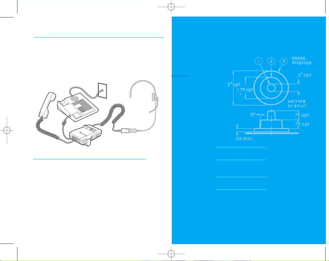
Connect the Vista amplifier to your telephone as shown.
Follow the four easy steps on the following pages for
complete installation details.
Amplifier Features
•SoundGuard®Plus™Sound Compression protects you
•from harsh noises, such as fax tones
•Call Clarity
™
System improves incoming and outgoing sound
•Switch easily between headset and handset
•Incoming and outgoing volume control
•Mute
1
VISTA.engl.mech 9/16/02 5:12 PM Page iv
Page 4
english 3english2
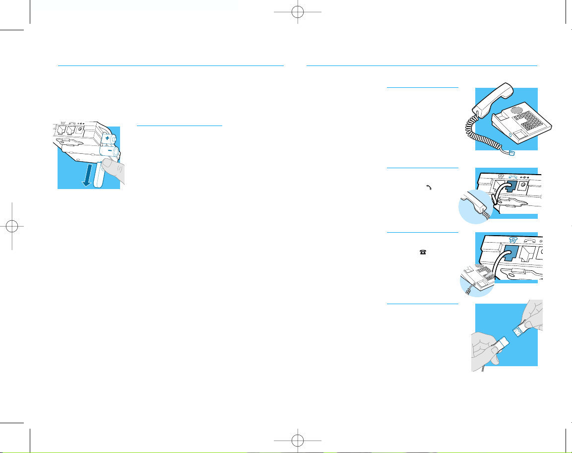
INSTALLATION STEPS
1. Unplug your telephone’s handset cord
from the telephone base.
2. Plug your telephone’s handset cord into
the Vista amplifier handset jack ( ).
3. Connect your telephone base to the
Vista amplifier telephone jack ( ) using
the short curly cord. On your telephone
base, plug the short curly cord into the
outlet normally used for your handset.
4. Plug the headset cord into the Quick
Disconnect
™
(QD) module on the long curly
cord coming from the front of the amplifier.
The QD will allow you to disconnect the
headset from the amplifier when you
are not using the phone, or need to
move away from the amplifier, while
leaving your headset in place.
STEP
2
attach to
phone and headset
INSTALLATION STEPS
The Vista Amplifier requires power
to work with most phones.
1. Remove the Battery Access Door located on
the side of the amplifier by placing your
thumb on the door and pushing down.
2. Install two AA alkaline batteries and
replace the door.
3. You will hear three “beeps“ through the
headset when the batteries are low.
STEP
1
install
batteries
VISTA.engl.mech 9/16/02 5:12 PM Page 2
Page 5

english 5english4
INSTALLATION STEPS
1. Put on headset.
2. Lift the phone’s handset off the cradle
and place it on your desk.
3. If you don’t hear a dial tone, adjust the
Telephone/Amplifier Compatibility
Switch as indicated below:
1. Remove the Telephone Compatibility
Switch Access Door by placing two fingers or thumbs on the raised bumps and
pushing down.
2. Remove the flat, plastic screwdriver
from the bottom of the amplifier by sliding it through the braces holding it in
place.
3. Make sure the amplifier is in the default
settings, and your telephone handset is
off of its cradle.
4. Using the screwdriver, slide the
Compatibility Switch until you hear a
clear dial tone. Experimenting with various switch settings will not harm the
amplifier or your telephone.
STEP
4
set telephone/amplifier
Compatibility Switch
INSTALLATION STEPS
These are the default settings for
headset use.
1. Headset /Handset Selector is depressed
(colored indicator showing).
2. Mute Switch is released (no colored
indicator showing).
3. Incoming Volume Thumbwheel is set to 4.
4. The Outgoing volume has been pre-set. You
can adjust it when you place your first call
(see page 6).
STEP
3
set default
settings
VISTA.engl.mech 9/16/02 5:12 PM Page 4
Page 6

MAKE A TEST CALL.
english 7
make
a test call
II
PAR T
1. Put on headset. Refer to your headset’s User Guide to
adjust the microphone position for best performance.
2. Lift the phone’s handset off the cradle and place it on your desk.
3. Make sure your Vista amplifier settings are in default. See
page 4 for details.
4. Call a friend or colleague.
5. Adjust the Incoming Volume using the Incoming Volume
Thumbwheel. Refer to page 10 for more details.
6. Adjust the Outgoing Volume Control until the person on
the other end can hear your voice at an appropriate level.
See page 10 for more details.
7. If your friend cannot hear you, or you hear a buzz or hum,
try changing the Compatibility Switch. See page 5 for more
details.
8. Try activating the Mute function by depressing the Mute
Switch (colored indicator showing). Release the Mute
Switch (no colored indicator showing) to deactivate the
Mute function. See page 11 for more details.
9. If you used batteries in your Vista amplifier, try removing the
batteries. If you lose power, your phone model requires
power for your Vista amplifier. Replace the batteries.
6
VISTA.engl.mech 9/16/02 5:12 PM Page 6
Page 7

LEARN THE BASICS.
Default settings
These are the default settings for
headset use:
1. Headset /Handset Selector is depressed
(colored indicator showing).
2. Mute Switch is released (no colored
indicator showing).
3. Incoming Volume Thumbwheel is set to 4.
Making and Receiving Calls with a
Headset
1. Put on headset.
2. Make sure the amplifier settings are in
default.
3. Lift the phone handset off the cradle
and place on your desk.
4. Make or receive your call. You will use
the dial pad and/or other features of
your telephone as you would normally.
5. To end the call, hang up the handset.
english 9
learn
the basics
DEFAULT SETTINGS
MAKING AND RECEIVING
CALLS WITH A HEADSET
ADJUSTING
MUTING A CALL
MAKING AND RECEIVING
CALLS WITH A HANDSET
•HEADSET INCOMING VOLUME
•HEADSET OUTGOING VOLUME
III
PAR T
8
VISTA.engl.mech 9/16/02 5:12 PM Page 8
Page 8

LEARN THE BASICS
Muting a Call
1. Activate the Mute function by depressing the
Mute switch (colored indicator showing).
2. Deactivate the Mute function by releasing the Mute switch (no colored
indicator showing).
Making and Receiving Calls with a
Handset
1. Release the Headset /Handset switch
(no colored indicator showing).
2. Use the phone handset as you normally
would.
11
LEARN THE BASICS
Adjusting Headset Incoming Volume
1. Adjust the volume by turning the
Thumbwheel on the top panel.
2. Try different volume settings. 1 is the
quietest and 9 is the loudest.
3. “Make a Test Call” (see page 7) provides
more details about adjusting your
incoming volume.
Adjusting Headset Outgoing Volume
1. Outgoing Volume is pre-set. Try making a
test call before adjusting (see page 7).
2. To access the Outgoing Volume Control,
remove the panel on the left-hand side of
the amplifier. The same panel houses the
Telephone/Amplifier Compatibility Switch.
3. Use the screwdriver attached to the bottom
of the amplifier to adjust the Outgoing
Volume Control. Turn clockwise to make
your voice louder to the caller. Turn
counter-clockwise to make your voice quieter to the caller.
4. Replace the panel door and the screwdriver.
english10 english
VISTA.engl.mech 9/16/02 5:12 PM Page 10
Page 9

maintenance
and troubleshooting
A
SECTION
12 english
MAINTENANCE AND
TROUBLESHOOTING
PROBLEM
ITEMS TO CHECK
I DO NOT HEAR A
DIAL TONE WHEN I
TRY TO MAKE OR
RECEIVE A PHONE
CALL.
If you are using batteries, confirm that they
are good and placed in the battery compartment correctly.
If you are using an AC Power Supply, confirm
that it is plugged in and the power outlet is
turned on.
Confirm that the Headset /Handset Selector
switch is depressed (colored indicator showing).
Confirm that you have lifted the telephone
handset out of the cradle.
Confirm that the telephone handset cable and
the short curly pigtail to the telephone are connected to the correct jacks. (see "Installation”)
Confirm that the Telephone/Amplifier
Compatibility Switch is in the correct setting for
your phone (see “Set the Telephone/Amplifier
Compatibility Switch” on page 5). You may
want to try moving the switch through all of
the positions until you hear a clear dial tone.
Experimenting with various switch settings will
not harm the amplifier or your phone.
The Plantronics Help Desk is ready to assist you!
Monday through Friday 8:00 AM to 5:00 PM PST
800 544-4660
Maintenance Hints
Trouble Shooting Guide
13
VISTA.engl.mech 9/16/02 5:12 PM Page 12
Page 10

15
MAINTENANCE AND
TROUBLESHOOTING
english14
I GET A LOW PITCHED
HUM IN MY HEADSET
SPEAKER AND/OR MY
CALLERS COMPLAIN
THEY CAN HEAR HUM.
I HEAR THREE ‘BEEPS’
IN THE HEADSET.
PROBLEM
ITEMS TO CHECK
MY CALLERS SAY
THAT THEY CAN’T
HEAR ME AT ALL OR
THEY CAN’T HEAR
ME VERY WELL.
Make sure the microphone of your headset is
positioned in front or near your mouth. If you
are using a “noise-cancelling” headset, the
position of the microphone is very important.
You may need to adjust the “Outgoing
Volume”. See “Adjusting Headset Outgoing
Volume” on page 10).
Confirm that the Telephone/Amplifier
Compatibility Switch is in the correct setting
for your phone (see "Set the Telephone/Amplifier
Compatibility Switch” on page 5). You may
want to try moving the switch through all of
the positions until your caller hears you clearly. Experimenting with various switch settings
will not harm the amplifier or your telephone.
Try moving the Telephone/Amplifier Compatibility
Switch through all of the positions until the
hum disappears. Experimenting with various
switch settings will not harm the amplifier or
your telephone.
If you are using batteries to power the Vista
Amplifier, the three ‘beeps’ tell you that the
batteries are low and need to be replaced.
See “Install Batteries”on page 2.
Trouble Shooting Guide
Maintenance Hints
parts
and accessories
B
SECTION
VISTA.engl.mech 9/16/02 5:12 PM Page 14
Page 11

english 17english16
REPLACEMENT PARTS AND
ACCESSORIES FOR VISTA
For information on accessories and spare
parts, call Plantronics at 1-800-544-4660,
or visit the Plantronics web site at
www.plantronics.com
AC Power Supply
ITEM PART #
AC Power Supply 26503-01
Telephone/Amplifier Compatibility
Slide Switch Door
ITEM PART
#
Telephone/Amplifier 44015-01
Compatibility
Slide Switch Door
Battery Door
ITEM PART #
Battery Door 44014-01
Amplifier to Telephone Coil Cable
(male to male modular plugs)
ITEM PART #
Amplifier to Telephone 40974-01
Coil Cable
Amplifier to QD Coil Cable
(QD to male modular plug)
ITEM PART #
Amplifier to QD 26716-01
Coil Cable
REPLACEMENT PARTS AND
ACCESSORIES FOR VISTA
Velcro®Amplifier Attachment Kit
ITEM PART #
Velcro Amplifier 17521-01
Attachment Kit
Amplifier Security Device
(attaches amplifier to desk.)
ITEM PART
#
Amplifier Security 40696-01
Device
Plantronics Custom Cradle Mate
(holds handset “off-hook” and a flashing
“BUSY” light indicates when headset is in use)
ITEM PART
#
Plantronics Custom 40715-01
Cradle Mate
Cradle Mate only
(easy-to-use device that mechanically holds
handset “off-hook”)
ITEM PART
#
Cradle Mate only 40714-01
VISTA.engl.mech 9/16/02 5:12 PM Page 16
Page 12

W ARRANTY AND SERVICE
english 19
W ARRANTY AND SERVICE
english18
WARRANTY AND SERVICE
The following warranty and service information applies only to the U.S. and Canada. For information in other countries, please contact your local distributor.
To obtain in or out of warranty service, please prepay shipment and return the unit to the appropriate
facility listed below:
IN THE UNITED STATES IN CANADA
Plantronics Service Center Plantronics Service Center
345 Encinal Street 1455 Pitfield Blvd.
Santa Cruz, CA 95060 Saint-Laurent, Quebec H4S 1G3
Tel. (80 0) 54 4-4 660 Tel. (800) 540- 8363
(831) 458-7700 (514) 956-8 363
Fax (80 0) 279-0162 Fax (514) 956-1825
Please use the original container, or pack the unit(s) in a sturdy carton with sufficient packing material to
prevent damage. Include the following information:
1. A proof-of-purchase indicating model number and date of purchase.
2. Bill-to address
3. Ship-to address
4. Number and description of units shipped
5. Name and telephone number of person to call, should contact be necessary
6. Reason for return and description of the problem
Damage occurring during shipment is deemed the responsibility of the carrier, and claims
should be made directly with the carrier.
The name Plantronics, the Plantronics logo and SoundGuard are registered trademarks of Plantronics, Inc.
Vista, Quick Disconnect, Call Clarity and SoundGuard Plus are trademarks of Plantronics, Inc.
Velcro is a registered trademark of Velcro USA.
FCC REGISTRATION INFORMATION
This equipment complies with Part 68 of the FCC rules. On the bottom of the modular adapter
is a label that contains, among other information, the FCC registration number and ringer equivalence number (REN) for this equipment. If requested, this information must be provided to the
telephone company.
The telephone company may make changes in its facilities, equipment, operation or procedures that
could affect the operation of the equipment. If this happens, the telephone company should provide
you advance notice in order for you to make the necessary modifications to maintain uninterrupted
services.
If you experience problems with your headset, please refer to the warranty section for information on
warranty and repair service. If the problem is causing harm to the telephone network, the telephone
company may request that you remove the equipment until the problem is resolved. In extreme cases, the
telephone company may be forced to disconnect your service before notifying you of the problem.
VISTA.engl.mech 9/16/02 5:12 PM Page 18
 Loading...