

Page 1

Page 2

Copyright
Copyright 2013 by PLANET Technology Corp. All rights reserved. No part of this publication may
be reproduced, transmitted, transcribed, stored in a retrieval system, or translated into any language
or computer language, in any form or by any means, electronic, mechanical, magnetic, optical,
chemical, manual or otherwise, without the prior written permission of PLANET.
PLANET makes no representations or warranties, either expressed or implied, with respect to the
contents hereof and specifically disclaims any warranties, merchantability or fitness for any particular
purpose. Any software described in this manual is sold or licensed "as is". Should the programs
prove defective following their purchase, the buyer (and not this company, its distributor, or its dealer)
assumes the entire cost of all necessary servicing, repair, and any incidental or consequential
damages resulting from any defect in the software. Further, this company reserves the right to revise
this publication and to make changes from time to time in the contents hereof without obligation to
notify any person of such revision or changes.
All brand and product names mentioned in this manual are trademarks and/or registered trademarks
of their respective holders.
Federal Communication Commission Interference Statement
This equipment has been tested and found to comply with the limits for a Class A digital device,
pursuant to part 15 of the FCC Rules. These limits are designed to provide reasonable
protection against harmful interference when the equipment is operated in a commercial
environme
nt. This equipment generates, uses, and can radiate radio frequency energy and, if not
installed and used in accordance with the instruction manual, may cause harmful interference to
radio communications. Operation of this equipment in a residential area is likely to cause harmful
interference in which case the user will be required to correct the interference at his/her own
expense. Any changes or modifications not expressly approved by PLANET could void the user’s
authority to operate this equipment under the rules and regulations of the FCC.
FCC Cau
tion:
To assure continued compliance, (example-use only shielded interface cables when connecting to
computer or peripheral devices) any changes or modifications not expressly approved by the party
responsible for compliance could void the user’s authority to operate the equipment.
This device complies with Part 15 of the FCC Rules. Operation is subject to the Following two
conditions:
(1) This device may not cause harmful interference
(2) This Device must accept any interference received, including interference that may cause
undesired operation.
Federal Communication Commission (FCC) Radiation Exposure Statement
This equipment complies with FCC radiation exposure set forth for an uncontrolled environment. In
order to avoid the possibility of exceeding the FCC radio frequency exposure limits, human proximity
to the antenna shall not be less than 20 cm (8 inches) during normal operation.
I
Page 3

CE Mark Warning
This is a Class B product. In a domestic environment, this product may cause radio interference, in
which case the user may be required to take adequate measures.
Energy Saving Note of the Device
This power required device does not support Standby mode operation.
For energy saving, please remove the DC-plug to disconnect the device from the power circuit.
Without remove the DC-plug, the device still consuming power from the power circuit. In the view of
Saving the Energy and reduce the unnecessary power consuming, it is strongly suggested to
remove the DC-plug for the device if this device is not intended to be active.
R&TTE Compliance Statement
This equipment complies with all the requirements of DIRECTIVE 1999/5/CE OF THE EUROPEAN
PARLIAMENT AND THE COUNCIL OF 9 March 1999 on radio equipment and telecommunication
terminal Equipment and the mutual recognition of their conformity (R&TTE).
The R&TTE Directive repeals and replaces in the directive 98/13/EEC (Telecommunications
Terminal Equipment and Satellite Earth Station Equipment) As of April 8, 2000.
Safety
This equipment is designed with the utmost care for the safety of those who install and use it.
However, special attention must be paid to the dangers of electric shock and static electricity when
working with electrical equipment. All guidelines of this and of the computer manufacture must
therefore be allowed at all times to ensure the safe use of the equipment.
WEEE regulation
To avoid the potential effects on the environment and human health as a result of the
presence of hazardous substances in electrical and electronic equipment, end users of
electrical and electronic equipment should understand the meaning of the crossed-out
wheeled bin symbol. Do not dispose of WEEE as unsorted municipal waste and have to
collect such WEEE separately.
II
Page 4

Revision
User’s Manual for PLANET 802.11a/n Wireless Outdoor Access Point
Model: WNAP-7206
Rev: 1.0 (January, 2013)
Part No. EM-WNAP-7206_v1.0 (2081-E10490-000)
III
Page 5

CONTENTS
Chapter 1. Product Introduction...........................................................................................................1
1.1 Package Contents ...............................................................................................................1
1.2 Product Description............................................................................................................2
1.3 Product Features................................................................................................................. 4
1.4 Product Specification ......................................................................................................... 5
Chapter 2. Hardware Installation ..........................................................................................................8
2.1 Hardware Description.........................................................................................................8
2.1.1 The Rear Panel......................................................................................................... 8
2.1.2 The Bottom Panel .....................................................................................................9
2.1.3 PoE Injector ............................................................................................................10
Chapter 3. Connecting to the AP........................................................................................................12
3.1 Preparation before Installation ........................................................................................ 12
3.1.1 Professional Installation Required .......................................................................... 12
3.1.2 Safety Precautions..................................................................................................12
3.2 Installation Precautions....................................................................................................12
3.3 Hardware Installation........................................................................................................ 14
3.4 Pole Mounting ...................................................................................................................16
3.4.1 Using the External Antenna ....................................................................................16
Chapter 4. Quick Installation Guide ................................................................................................... 17
4.1 Manual Network Setup - TCP/IP Configuration..............................................................17
4.1.1 Configure the IP Address Manually ........................................................................17
4.2 Starting Setup in the Web UI............................................................................................ 21
Chapter 5. Configuring the AP............................................................................................................ 25
5.1 Status.................................................................................................................................. 25
5.2 Quick Setup ....................................................................................................................... 28
5.3 WPS .................................................................................................................................... 28
5.3.1 Push Button Config (PBC)......................................................................................29
5.3.2 PIN Input Config (PIN)............................................................................................32
5.4 Operation Mode.................................................................................................................36
5.5 Network .............................................................................................................................. 37
5.5.1 LAN.........................................................................................................................37
5.5.2 WAN........................................................................................................................38
5.5.2.1. Dynamic IP.....................................................................................................................39
5.5.2.2. Static IP..........................................................................................................................40
5.5.2.3. PPPoE/Russia PPPoE...................................................................................................42
5.5.2.4. L2TP/Russia L2TP.........................................................................................................45
5.5.2.5. PPTP/Russia PPTP .......................................................................................................48
5.5.2.6. BigPond Cable...............................................................................................................50
IV
Page 6

5.5.3 MAC Clone .............................................................................................................52
5.6 Wireless..............................................................................................................................53
5.6.1 Wireless Settings ....................................................................................................53
5.6.1.1. Access Point Mode ........................................................................................................ 53
5.6.1.2. Multi-SSID Mode............................................................................................................55
5.6.1.3. Client Mode (Client Bridge)............................................................................................58
5.6.1.4. Repeater Mode .............................................................................................................. 61
5.6.1.5. Universal Repeater Mode ..............................................................................................63
5.6.1.6. Bridge with AP Mode (PtP & PtMP)................................................................................65
5.6.1.7. AP Router Mode ............................................................................................................68
5.6.1.8. AP Client Router Mode (WISP+AP)...............................................................................70
5.6.2 Wireless Security ....................................................................................................74
5.6.2.1. Operation Mode – Access Point..................................................................................... 75
5.6.2.2. Operation Mode – Multi-SSID ........................................................................................ 78
5.6.2.3. Operation Mode – Client ................................................................................................ 80
5.6.2.4. Operation Mode – Repeater........................................................................................... 82
5.6.2.5. Operation Mode – Universal Repeater........................................................................... 84
5.6.2.6. Operation Mode – Bridge with AP..................................................................................86
5.6.2.7. Operation Mode – AP Router ......................................................................................... 88
5.6.2.8. Operation Mode – AP Client Router............................................................................... 91
5.6.3 Wireless MAC Filtering ...........................................................................................93
5.6.4 Wireless Advanced .................................................................................................94
5.6.5 Antenna Alignment..................................................................................................96
5.6.6 Distance Setting...................................................................................................... 96
5.6.7 Throughput Monitor ................................................................................................98
5.6.8 Wireless Statistics................................................................................................... 99
5.7 DHCP .................................................................................................................................. 99
5.7.1 DHCP Settings...................................................................................................... 100
5.7.2 DHCP Clients List .................................................................................................101
5.7.3 Address Reservation ............................................................................................102
5.8 Forwarding....................................................................................................................... 103
5.8.1 Virtual Servers ......................................................................................................103
5.8.2 Port Triggering ...................................................................................................... 105
5.8.3 DMZ ...................................................................................................................... 108
5.8.4 UPnP.....................................................................................................................108
5.9 Security ............................................................................................................................ 111
5.9.1 Basic Security ....................................................................................................... 111
5.9.2 Advanced Security................................................................................................ 113
5.9.3 Local Management ............................................................................................... 115
5.9.4 Remote Management ........................................................................................... 116
5.10 Parental Control .............................................................................................................. 117
5.11 Access Control................................................................................................................118
V
Page 7

5.11.1 Rule....................................................................................................................... 119
5.11.2 Host.......................................................................................................................121
5.11.3 Target....................................................................................................................122
5.11.4 Schedule...............................................................................................................123
5.12 Static Routing..................................................................................................................125
5.13 Bandwidth Control ..........................................................................................................126
5.13.1 Control Settings ....................................................................................................126
5.13.2 Rules List .............................................................................................................. 127
5.14 IP & MAC Binding............................................................................................................129
5.14.1 Binding Settings....................................................................................................129
5.14.2 ARP List................................................................................................................130
5.15 Dynamic DNS................................................................................................................... 131
5.16 System Tools ...................................................................................................................134
5.16.1 Time Settings........................................................................................................134
5.16.2 Diagnostic ............................................................................................................. 135
5.16.3 Ping Watch Dog....................................................................................................137
5.16.4 Speed Test............................................................................................................138
5.16.5 Firmware Upgrade ................................................................................................139
5.16.6 Factory Defaults.................................................................................................... 140
5.16.7 Backup & Restore.................................................................................................140
5.16.8 Reboot ..................................................................................................................141
5.16.9 Password ..............................................................................................................141
5.16.10 System Log...........................................................................................................142
5.16.11 Statistics................................................................................................................145
Appendix A: FAQ...............................................................................................................................147
A.1 What and how to find my PC’s IP and MAC address? ...................................................147
A.2 What is Wireless LAN?...................................................................................................... 147
A.3 What are ISM bands?.........................................................................................................147
A.4 How does wireless networking work?............................................................................. 147
A.5 What is BSSID? ..................................................................................................................148
A.6 What is ESSID? .................................................................................................................. 148
A.7 What are potential factors that may causes interference?............................................148
A.8 What are the Open System and Shared Key authentications?.....................................149
A.9 What is WEP?..................................................................................................................... 149
A.10 What is Fragment Threshold? ........................................................................................149
A.11 What is RTS (Request to Send) Threshold? .................................................................150
A.12 What is Beacon Interval? ................................................................................................ 150
A.13 What is Preamble Type?.................................................................................................. 150
A.14 What is SSID Broadcast?................................................................................................150
A.15 What is Wi-Fi Protected Access (WPA)? ....................................................................... 151
VI VII
Page 8

A.16 What is WPA2? .................................................................................................................151
A.17 What is 802.1x Authentication?......................................................................................151
A.18 What is Temporal Key Integrity Protocol (TKIP)?.........................................................151
A.19 What is Advanced Encryption Standard (AES)?...........................................................151
A.20 What is Inter-Access Point Protocol (IAPP)?................................................................ 152
A.21 What is Wireless Distribution System (WDS)? .............................................................152
A.22 What is Universal Plug and Play (UPnP)?.....................................................................152
A.23 What is Maximum Transmission Unit (MTU) Size? ...................................................... 152
A.24 What is Clone MAC Address? ........................................................................................ 152
A.25 What is DDNS?................................................................................................................. 152
A.26 What is NTP Client?......................................................................................................... 152
A.27 What is VPN?....................................................................................................................153
A.28 What is IPSEC? ................................................................................................................ 153
A.29 What is WLAN Block Relay between Clients? ..............................................................153
A.30 What is WMM?..................................................................................................................153
A.31 What is WLAN ACK TIMEOUT? ......................................................................................153
A.32 What is Modulation Coding Scheme (MCS)?................................................................153
A.33 What is Frame Aggregation? ..........................................................................................153
A.34 What is Guard Intervals (GI)? ......................................................................................... 154
Appendix B: Configuring the PC in Windows 7 .............................................................................155
Appendix C: Specifications..............................................................................................................158
Appendix D: Factory Default Settings ............................................................................................161
Page 9
User Manual of WNAP-7206
Chapter 1. Product Introduction
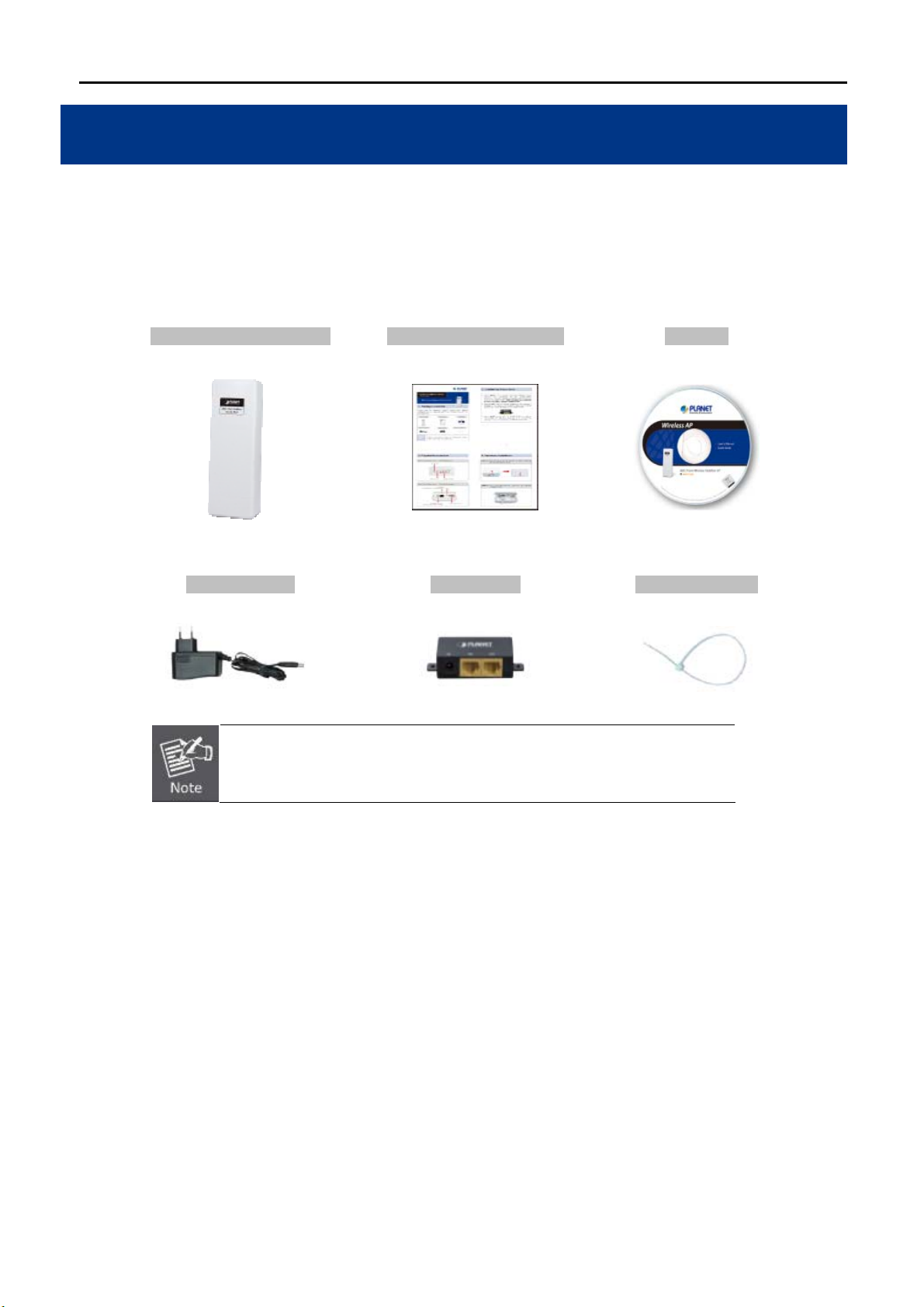
1.1 Package Contents
Thank you for choosing PLANET WNAP-7206. Before installing the AP, please verify the contents inside the
package box.
WNAP-7206 Wireless AP Quick Installation Guide CD-ROM
Power Adapter PoE Injector Mounting Tie x 2
If there is any item missed or damaged, please contact the seller
immediately.
(User Manual included)
-1-
Page 10

User Manual of WNAP-7206
1.2 Product Description
High Power Outdoor Wireless Coverage
PLANET Technology introduces the latest high power outdoor wireless LAN solution - the outdoor wireless AP,
WNAP-7206. It provides higher transmit power, better performance, and widely coverage than standard
outdoor wireless AP. The WNAP-7206 is compatible with IEEE 802.11a/n standard supporting the data rate up
to 150Mbps in 802.11n mode. The WNAP-7206 not only has built-in 15dBi panel Antenna but also reserves
one RP-SMA Type Antenna Connector to allow versatile antenna installations and multiple adjustable transmit
output power controller. Therefore, the WNAP-7206 is quite suitable for widely open space applications.
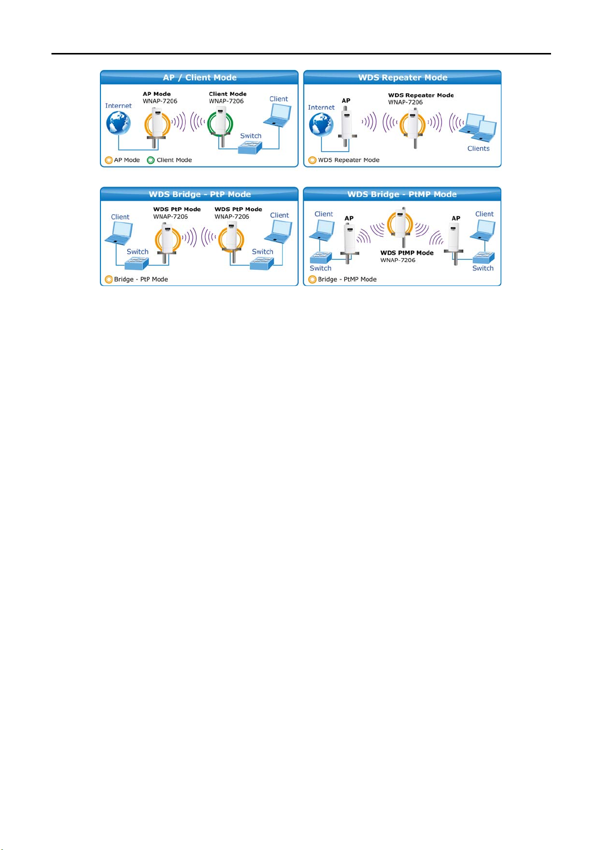
Multiple Operating & Wireless Modes
The WNAP-7206 supports multiple wireless communication connectivity (AP / Client CPE / WDS PtP / WDS
PtMP / Repeater / Universal Repeater) allowing for various application requirements and thus it gives users
more comprehensive experience when using the WNAP-7206. It helps users to easily build a wireless network
and extend the wireless range of existing wireless network.
The WNAP-7206 also supports WISP mode, so CPE users could easily connect to Internet via WISP provider
or connect to a wired network.
-2-
Page 11
Advanced Security and Management
User Manual of WNAP-7206
In aspect of security, besides 64/128/152-bit WEP encryption, the WNAP-7206 integrates WPA / WPA2,
WPA-PSK / WPA2-PSK to secure and protect your wireless LAN. The wireless MAC filtering and SSID
broadcast control consolidate the wireless network security and prevent unauthorized wireless connection. To
fulfill enterprise and various applications demand, the WNAP-7206 enhances security and management
features such as multiple SSID support. It can create up to 4 virtual standalone AP with 4 different SSID
according to individual security level and encryption scheme of various wireless devices.
Highly Reliable Outdoor Device
The WNAP-7206 is perfectly suitable to be installed in outdoor environments and exposed locations. Its
built-in 15KV ESD and 4000V lightning protection can withstand storm and prevent damage from lightning
surges. Furthermore, the WNAP-7206 can perform stably under rigorous weather conditions including heavy
rain and wind by its Outdoor Weatherproof case protection. With the proprietary Power over Ethernet (PoE)
design, the WNAP-7206 can be easily applied in any area where power outlets are not available. It is the best
way using the WNAP-7206 to build outdoor wireless access applications between buildings on campuses,
business, rural areas and etc.
Easy Installation & Management
With User-friendly Web UI and step by step Setup Wizard, the WNAP-7206 is easier to install, even for users
who never experience setting up a wireless network. Furthermore, with SNMP-Based management interface,
the WNAP-7206 is convenient to be managed and configured remotely.
-3-
Page 12

1.3 Product Features
Industrial Compliant Wireless LAN & LAN
Compliant with IEEE 802.11n wireless technology capable of up to 150Mbps data rate
Backward compatible with 802.11a standard
Equipped with 10/100Mbps RJ-45 Ports for LAN & WAN, Auto MDI/ MDI-X supported
RF Interface Characteristics
Built-in 15dBi directional antenna
High Output Power up to 500mW with multiple adjustable transmit power control
Reserve RP-SMA Type Connector
Outdoor Environmental Characteristics
Outdoor weatherproof enclosure, with built-in 15KV ESD and 4000V lightning protection
Passive Power over Ethernet design
User Manual of WNAP-7206
Operating temperature: -30~70 Degree C
Multiple Operation & Wireless Mode
Multiple Operation Modes: Bridge, Gateway, Ethernet Converter
Multiple Wireless Modes: AP, Client CPE (WISP), WDS PtP, WDS PtMP, Repeater, Universal
Repeater
Supports Multiple SSID allowing users to access different networks through one single AP
Supports WMM (Wi-Fi Multimedia)
Secure Network Connection
Advanced security: 64/128/152-bit WEP, WPA / WPA2, and WPA-PSK / WPA2-PSK (TKIP/AES)
Supports NAT firewall features, with SPI function to protect against DoS attacks
Supports IP / Protocol-based access control and MAC Filtering
Fixed-network Broadband Router
Supported connection types: Dynamic / Static IP / PPPoE / PPTP / L2TP / Russia Dual-Access
Supports multiple sessions IPSec, L2TP and PPTP VPN pass-through
Supports Virtual Server, DMZ and Port Triggering for various networking applications
Supports DHCP Server, UPnP, Dynamic DNS
Easy Installation & Management
User-friendly Web-Based UI and SNMP-Based management
Quick Setup Wizard for easy configuration
Remote Management allows configuration from a remote site
Intelligent Antenna Alignment tool speeds up field deployment
System status monitoring includes DHCP Client, System Log
-4-
Page 13

1.4 Product Specification
User Manual of WNAP-7206
Product
Hardware
Standard compliance
Memory
Button
LED
PoE
Interface
Antenna
WNAP-7206
150Mbps 802.11a/n Wireless Outdoor Access Point
IEEE 802.11a/n
IEEE 802.3
IEEE 802.3u
IEEE 802.3x
32 Mbytes DDR SDRAM
4 Mbytes Flash
Reset Button x 1
Provides 4-Level signal LED indicator
Passive PoE (Up to 60 meters)
Wireless IEEE 802.11a/n
LAN / WAN: 10/100Base-TX, Auto-MDI/MDIX x 1
Grounding Terminal x 1
Internal (Default): 15dBi directional antenna (Dual-Polarization)
Horizontal: 60 degree
Vertical: 14 degree
External (Option): RP-SMA Female type Connector
Switchable by Software
For External Antenna Mode, attach antenna before power on.
Data Rate
Media Access Control
Modulation
Frequency Band
Operating Channel
802.11a: 54, 48, 36, 24, 18, 12, 9 and 6Mbps
802.11n (20MHz): up to 72Mbps
802.11n (40MHz): up to 150Mbp
CSMA/CA
Transmission / Emission Type: OFDM
Data modulation type: OFDM with BPSK, QPSK, 16-QAM, 64-QAM
5.180-5.240GHz; 5.745-5.825GHz
5.180GHz-CH36
5.200GHz-CH40
5.220GHz-CH44
5.240GHz-CH48
5.745GHz-CH149
5.765GHz-CH153
5.785GHz-CH157
5.805GHz-CH161
5.825GHz-CH165
*The actual channels will vary depends on the regulation in different
regions and countries.
-5-
Page 14
User Manual of WNAP-7206
RF Output Power
Receiver Sensitivity
Output Power Control
Power Requirements
Power Adapter
802.11a: 27 ± 1dBm
802.11n: 24 ± 1dBm
802.11a:
54M: -77dBm
48M: -79dBm
36M: -83dBm
24M: -86dBm
18M: -91dBm
12M: -92dBm
9M: -93dBm
6M: -94dBm
High (default)
Middle
Low
Passive PoE 12V
Pin 4,5 VDC+
Pin 7,8 VDC-
12V DC, 1A (switching)
802.11n:
150M: -73dBm
121.5M: -76dBm
108M: -77dBm
81M: -81dBm
54M: -84dBm
40.5M: -88dBm
27M: -91dBm
13.5M: -93dBm
Environment & Certification
Operation
Storage
Enclosure
Regulatory
Software
LAN
WAN
VPN Passthrough
Operating Mode
Temperature: -30~70 Degree C, Humidity: 10~90% non-condensing
Temperature: -40~70 Degree C, Humidity: 5~95% non-condensing
Outdoor Weatherproof design
15KV ESD & 4000V Lightning Protection
Grounding Terminal Integrated
CE / FCC / RoHS
Built-in DHCP server supporting static IP address distributing
Supports UPnP, Dynamic DNS
Supports Flow Statistics
IP & MAC Binding
IP / Protocol-based Bandwidth Control
Static IP
Dynamic IP
PPPoE / Russia PPPoE
PPTP / Russia PPTP
L2TP / Russia L2TP
BigPond Cable
PPTP
L2TP
IPSec
Standard AP (Wireless AP)
AP Router (Wireless Broadband Router)
AP Client Router (WISP Client Router)
-6-
Page 15

Firewall
Wireless Mode
User Manual of WNAP-7206
NAT firewall with SPI (Stateful Packet Inspection)
NAT with ALG (Application Layer Gateway)
Built-in NAT server supporting Port Triggering, Virtual Server, and DMZ
Built-in firewall with IP address / MAC / DNS filtering
Supports ICMP-FLOOD, UDP-FLOOD, TCP-SYN-FLOOD filter, DoS
protection
AP
Client
WDS PTP
WDS PTMP
WDS Repeater (AP+WDS)
Universal Repeater (AP+Client)
Channel Width
Wireless Isolation
Wireless Security
Multiple SSID
Max. Wireless Client
Max. WDS AP
Max. Wired Client
WMM
NTP
Management
20MHz / 40MHz
Enable to isolate each connected wireless clients
64/128/152-bits WEP, WPA, WPA-PSK, WPA2, WPA2-PSK
Wireless MAC address filtering
Enable/Disable SSID Broadcast
Up to 3
25
4
60
Supports Wi-Fi Multimedia
Network Time Management
Web-Based (HTTP) management interface
Supports SNMP v1/v2 agent with MIB-II
Remote management
SNTP time synchronize
Easy firmware upgrade
Diagnostic tool
Configuration Backup & Restore
DHCP Client List
System Log supports auto mail and save to local host
Ping Watch Dog allows you to continuously monitor the particular
connection between the device and a remote host.
Throughput Monitor provides real-time wireless throughput information
Speed Test helps to test the connection speed
-7-
Page 16
User Manual of WNAP-7206
Chapter 2. Hardware Installation
Please follow the instructions below to connect WNAP-7206 to the existing network devices and your
computers.
2.1 Hardware Description
Dimension: 250 x 85 x 60.5 mm (W x D x H)
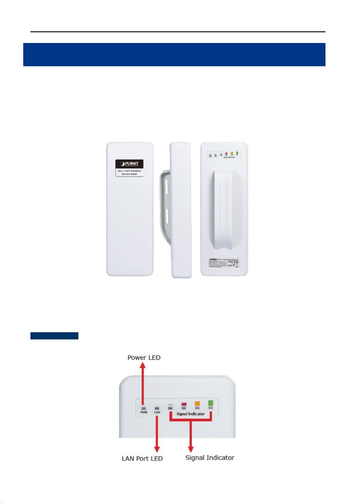
2.1.1 The Rear Panel
Rear Panel - LED
Figure 2-1 Three-way View
Figure 2-2 LED
-8-
Page 17
LED definition
LED State Meaning
User Manual of WNAP-7206
Power
On System On
Off System Off
Signal Indicator
(Client/Repeater Mode)
On Indicates the wireless signal strength of remote AP
Off No remote wireless signal
On Port linked.
WAN
Off No link.
Blinking Data is transmitting or receiving on the WAN interface.
LAN
On Port linked.
Off No link.
Blinking Data is transmitting or receiving on the LAN interface.
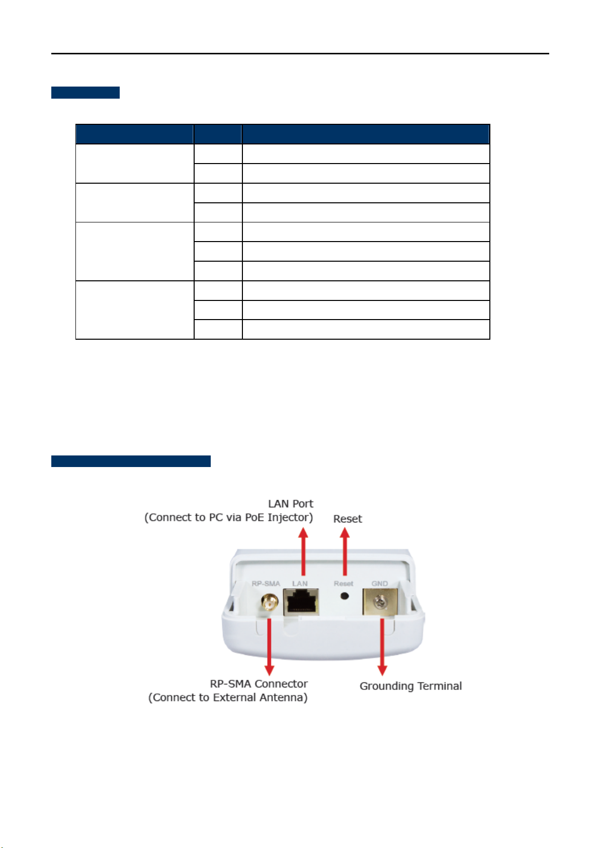
2.1.2 The Bottom Panel
The Bottom panel provides the physical connectors connected to the antenna and any other network devices.
Figure 2-3 shows the Bottom panel of WNAP-7206, and the Figure 2-4 shows the power warning of
WNAP-7206.
Bottom Panel – Port & Connector
Figure 2-3 Port & Connector
-9-
Page 18
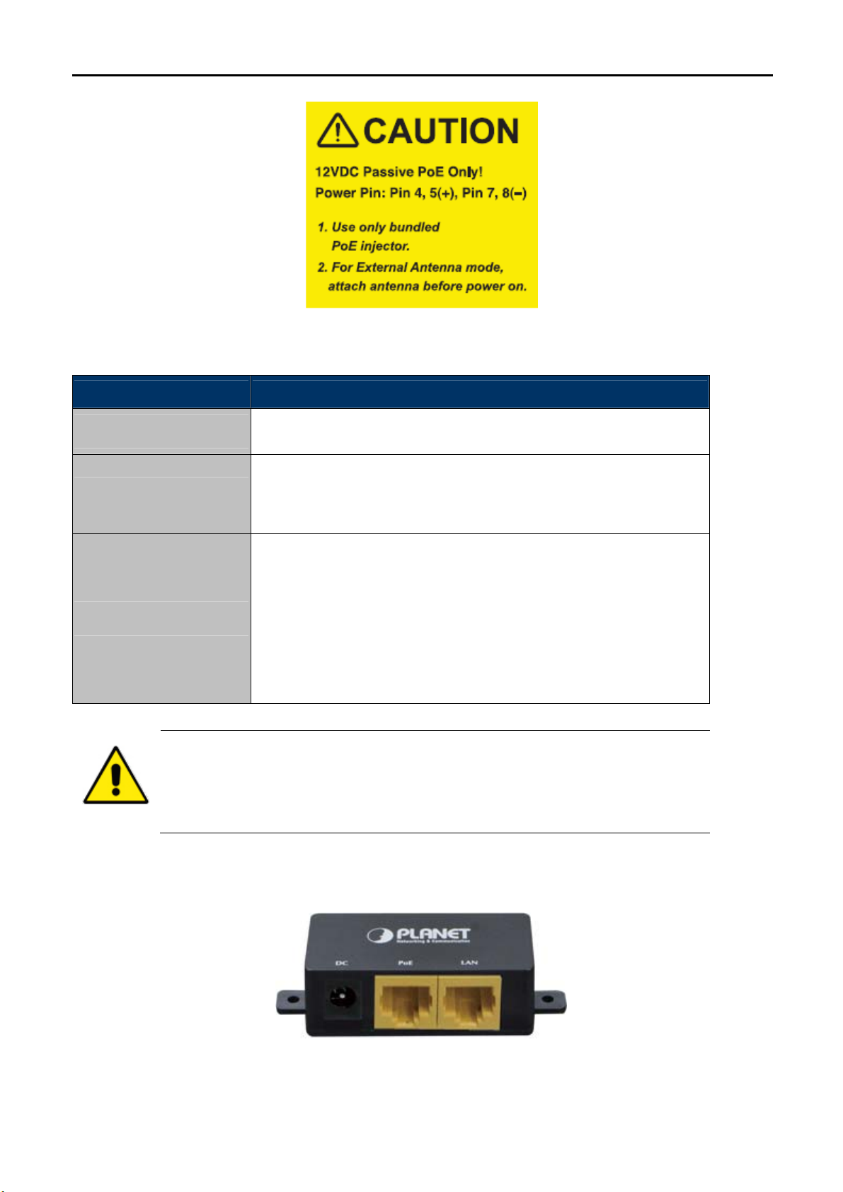
User Manual of WNAP-7206
Figure 2-4 Warning label
Interface Function
RP-SMA Connector
LAN
Reset
1. For External Antenna Mode, you MUST physically attach antenna before power
2. For using external antenna, you should configure the Antenna Switch from
For external antenna. You can use the RP-SMA connector to connect
with 5GHz external antenna.
The RJ-45 sockets allow LAN connection through Category 5 cables.
Support auto-sensing on 10/100M speed and half/ full duplex; comply
with IEEE 802.3/ 802.3u respectively.
There are two ways to reset the AP’s factory defaults:
Use the Factory Defaults function: on System Tools -> Factory
Defaults page in the AP’s Web-based Utility.
Use the Factory Default Reset button: Press and hold the Reset
button until Wireless Signal Strength LEDs flash, and then the AP
will reboot.
on.
“Internal” to “External” via Web UI.
2.1.3 PoE Injector
Figure 2-5 Top view of PoE Injector
-10-
Page 19

Figure 2-6 Warning Label of PoE Injector
User Manual of WNAP-7206
-11-
Page 20

User Manual of WNAP-7206
Chapter 3. Connecting to the AP
3.1 Preparation before Installation
3.1.1 Professional Installation Required
Please seek assistance from a professional installer who is well trained in the RF installation and knowledgeable
in the local regulations.
3.1.2 Safety Precautions
1. To keep you safe and install the hardware properly, please read and follow these safety precautions.
2. If you are installing WNAP-7206 for the first time, for your safety as well as others’, please seek assistance
from a professional installer who has received safety training on the hazards involved.
3. Keep safety as well as performance in mind when selecting your installation site, especially where there
are electric power and phone lines.
4. When installing WNAP-7206, please note the following things:
Do not use a metal ladder;
Do not work on a wet or windy day;
Wear shoes with rubber soles and heels, rubber gloves, long sleeved shirt or jacket.
5. When the system is operational, avoid standing directly in front of it. Strong RF fields are present when the
transmitter is on.
3.2 Installation Precautions
Users MUST use a proper and well-installed surge arrestor and grounding kit with WNAP-7206;
otherwise, a random lightening could easily cause fatal damage to WNAP-7206. EMD (Lightning)
DAMAGE IS NOT COVERED UNDER WARRANTY.
Users MUST use the “Power cord & PoE Injector” shipped in the box with the WNAP-7206. Use of
other options will cause damage to the WNAP-7206.
Users MUST power off the WNAP-7206 first before connecting the external antennas to it; otherwise,
damage might be caused to the WNAP-7206 itself.
-12-
Page 21

User Manual of WNAP-7206
OUTDOOR INSTALLATION WARNING
!
IMPORTANT SAFETY PRECAUTIONS:
LIVES MAY BE AT RISK! Carefully observe these instructions and any special instructions that are included with the
equipment you are installing.
CONTACTING POWER LINES CAN BE LETHAL. Make sure no power
lines are anywhere where possible contact can be made. Antennas, masts,
towers, guy wires or cables may lean or fall and contact these limes.
People may be injured or killed if they are touching or holding any part of
equipment when it contacts electric lines. Make sure there is NO possibility
that equipment or personnel can come in contact directly or indirectly with
power lines.
Assume all overhead lines are power lines.
The horizontal distance from a tower, mast or antenna to the nearest power line should be at least twice the total length of
the mast/antenna combination. This will ensure that the mast will not contact power if it falls either during installation or later.
TO AVOID FALLING, USE SAFE PROCEDURES WHEN WORKING AT HEIGHTS ABOVE GROUND.
Select equipment locations that will allow safe, simple equipment installation.
Don’t work alone. A friend or co-worker can save your life if an accident happens.
Use approved non-conducting lasers and other safety equipment. Make sure all equipment is in good repair.
If a tower or mast begins falling, don’t attempt to catch it. Stand back and let it fall.
If anything such as a wire or mast does come in contact with a power line, DON’T TOUCH IT OR ATTEMPT TO
MOVE IT. Instead, save your life by calling the power company.
Don’t attempt to erect antennas or towers on windy days.
MAKE SURE ALL TOWERS AND MASTS ARE SECURELY GROUNDED, AND ELECTRICAL CABLES CONNECTED TO
ANTENNAS HAVE LIGHTNING ARRESTORS. This will help prevent fire damage or human injury in case of lightning, static
build-up, or short circuit within equipment connected to the antenna.
The base of the antenna mast or tower must be connected directly to the building protective ground or to one or more
approved grounding rods, using 1 OAWG ground wire and corrosion-resistant connectors.
Refer to the National Electrical Code for grounding details.
IF A PERSON COMES IN CONTACT WITH ELECTRICAL POWER, AND CANNOT MOVE:
DON’T TOUCH THAT PERSON, OR YOU MAY BE ELECTROCUTED.
Use a non-conductive dry board, stick or rope to push or drag them so they no longer are in contact with electrical
power.
Once they are no longer contacting electrical power, administer CPR if you are certified, and make sure that emergency
-13-
Page 22
User Manual of WNAP-7206
medical aid has been requested.
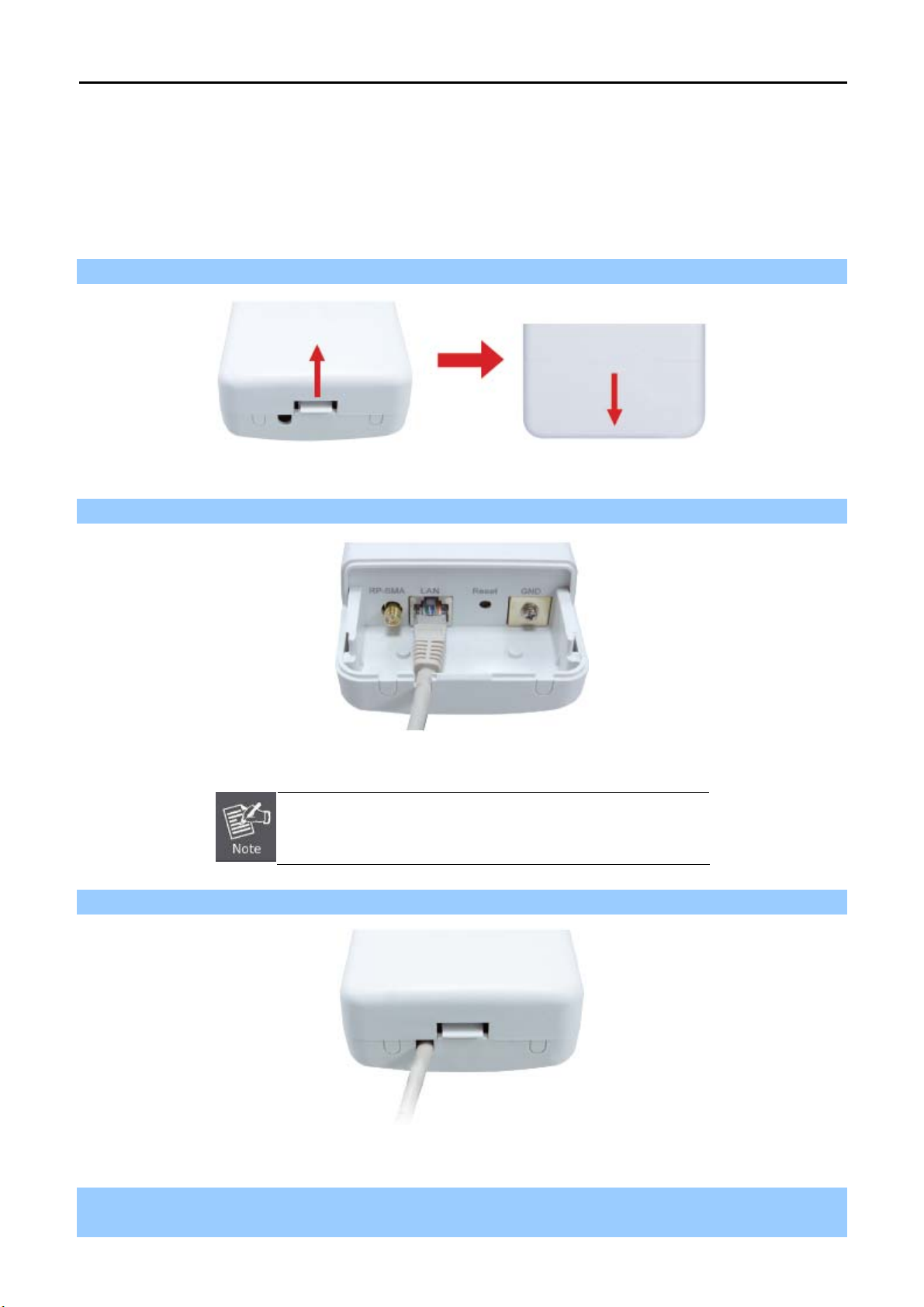
3.3 Hardware Installation
Please install the AP according to the following steps. Don't forget to pull out the power plug and keep your
hands dry.
Step 1. Push the latch in the bottom of WNAP-7206 to remove the sliding cover.
Figure 3-1
Step 2. Plug the RJ-45 Ethernet cable into the LAN Port of WNAP-7206.
Figure 3-2
RJ-45 8P8C Ethernet cable is required.
Step 3. Slide the cover back to seal the bottom of the WNAP-7206.
Figure 3-3
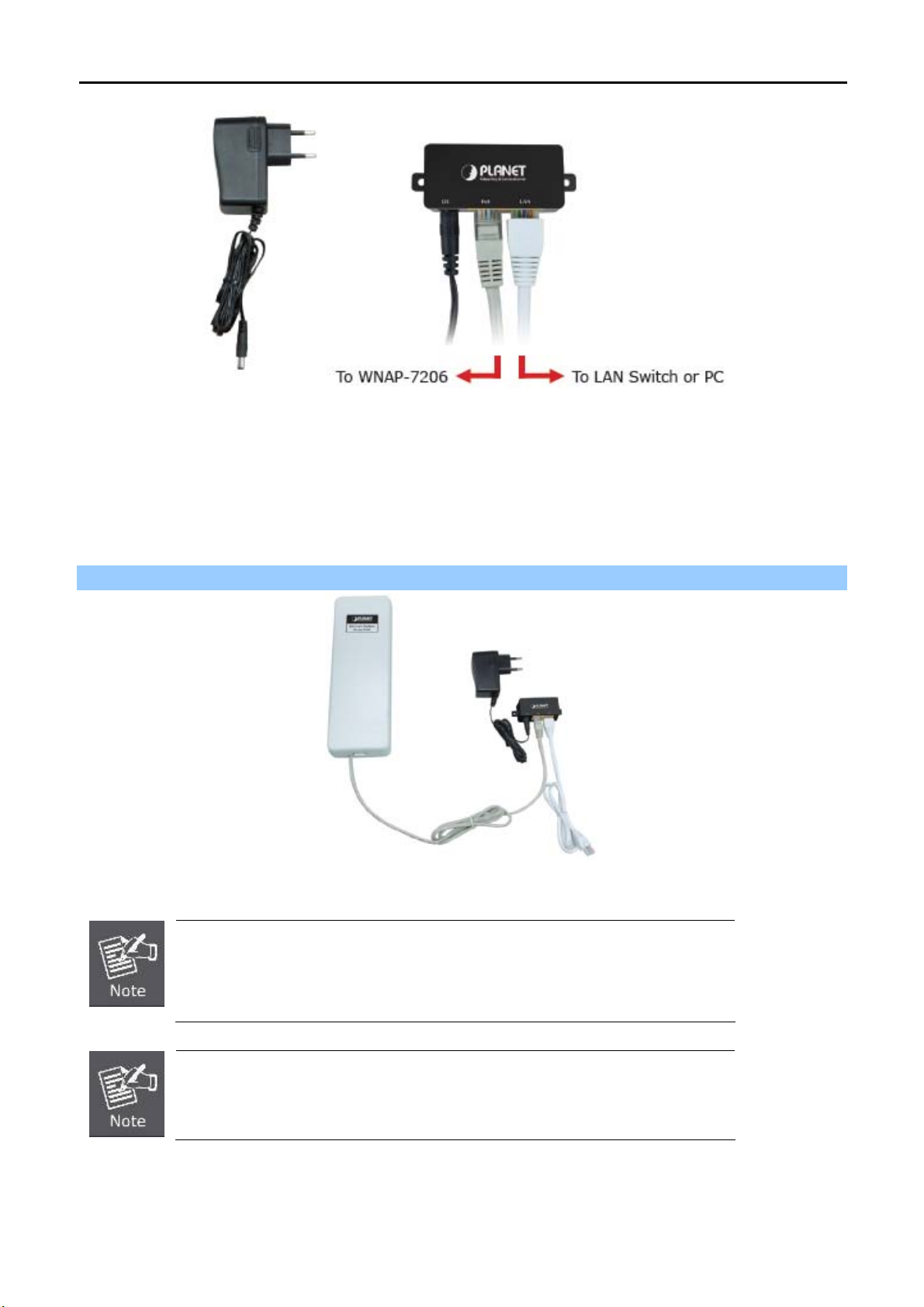
Step 4. Take out the power cord and PoE injector, plug the power cord into the DC port and plug the other side
of the RJ-45 cable in the STEP 2 into the POE port of the PoE injector.
-14-
Page 23
User Manual of WNAP-7206
Figure 3-4
DC: Insert adapter
POE: This hole is linked to LAN port of the WNAP-7206 with RJ-45 Ethernet cable.
LAN: This hole is linked to LAN port of PC/Hub or Router/xDSL modem device with RJ-45 Ethernet cable.
Step 5. Successful installation.
Figure 3-5
It will take about 50 seconds to complete the boot up sequence after powered on
the Outdoor AP/Router; Power LED will be active, and after that the LAN Activity
LED will be flashing to show the LAN interface is enabled and working now.
To avoid thunder strike, consider to install ELA-100, thunder arrester toward the
CPE AP and the PoE injector.
-15-
Page 24
User Manual of WNAP-7206
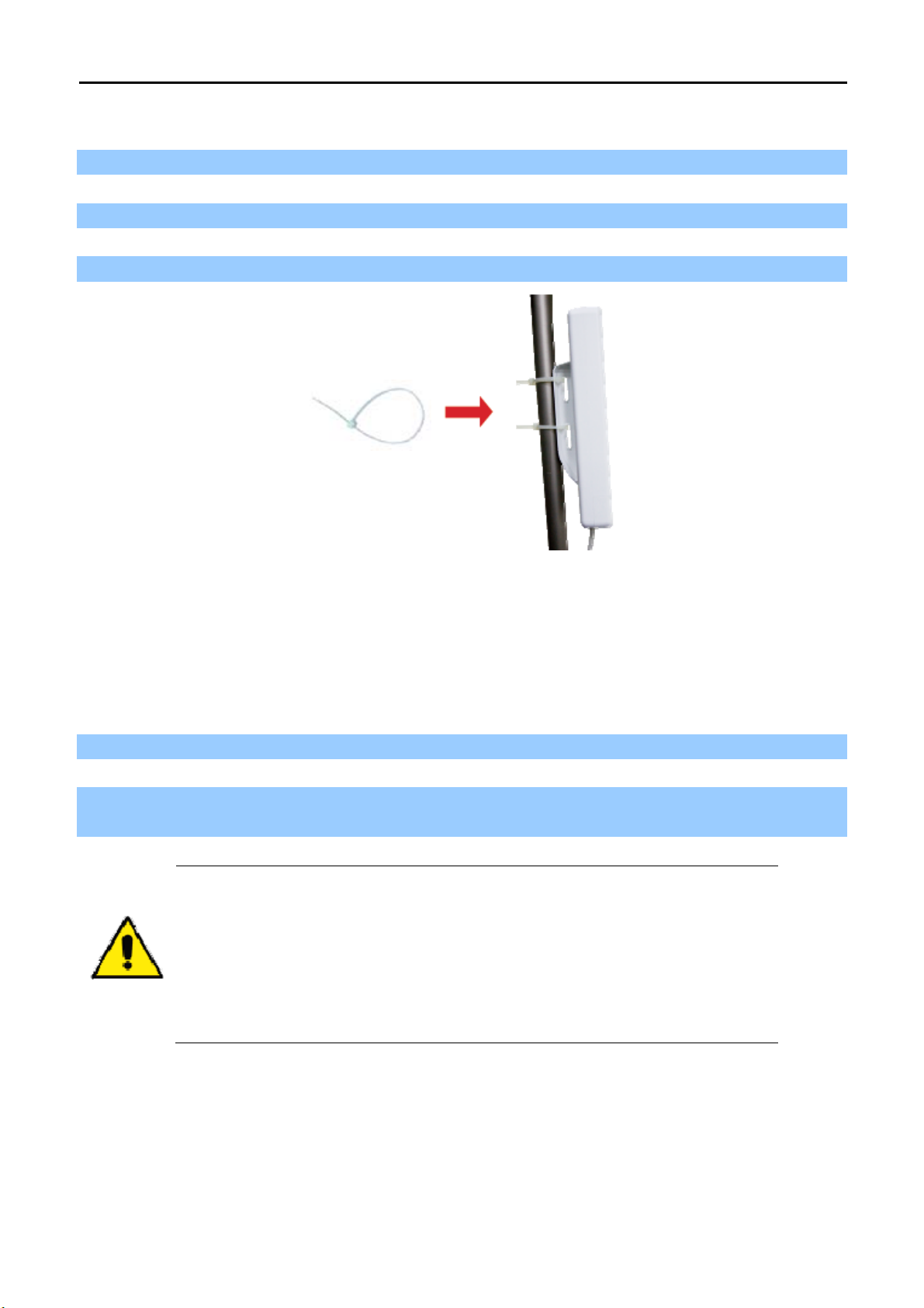
3.4 Pole Mounting
Step 1. Turn the WNAP-7206 over. Put the pole mounting tie through the middle hole of it.
Step 2. Mount WNAP-7206 steadily to the pole by fastening the mounting tie tightly.
Step 3. Now you have completed the hardware installation of WNAP-7206 as figure below.
Figure 3-6 Pole Mountin
g
3.4.1 Using the External Antenna
If you prefer to use the external antenna with RP-SMA Type connector for your application instead of the built-in
directional antenna, please follow the steps below.
Step 1. Connect your antenna with the RP-SMA Type connector on the bottom of WNAP-7206.
Step 2. Power on the WNAP-7206, and then go to Wireless -> Wireless Advanced to configure the Antenna
Setting to “External Antenna”.
1. If you are going to use an external antenna on WNAP-7206, get some cable in
advance.
1. Users MUST power off the WNAP-7206 first before connecting the external
antenna to it. Do not switch from built-in antenna to the external antenna from
WEB management without physically attaching the external antenna onto the
WNAP-7206; otherwise, damage might be caused to the WNAP-7206 itself.
-16-
Page 25

User Manual of WNAP-7206
Chapter 4. Quick Installation Guide
This chapter will show you how to configure the basic functions of your Wireless AP using Quick Setup within
minutes.
A computer with wired Ethernet connection to the Wireless AP is required for the first-time
configuration.
4.1 Manual Network Setup - TCP/IP Configuration
The default IP address of the WNAP-7206 is 192.168.1.1. And the default Subnet Mask is 255.255.255.0. These
values can be changed as you desire. In this guide, we use all the default values for description.
Connect the WNAP-7206 with your PC by an Ethernet cable plugging in LAN port of PoE injector in one side and
in LAN port of PC in the other side. Please power on the WNAP-7206 by the PoE injector shipping with
WNAP-7206.
In the following sections, we’ll introduce how to install and configure the TCP/IP correctly in Windows XP. And
the procedures in other operating systems are similar. First, make sure your Ethernet Adapter is working, and
refer to the Ethernet adapter’s manual if needed.
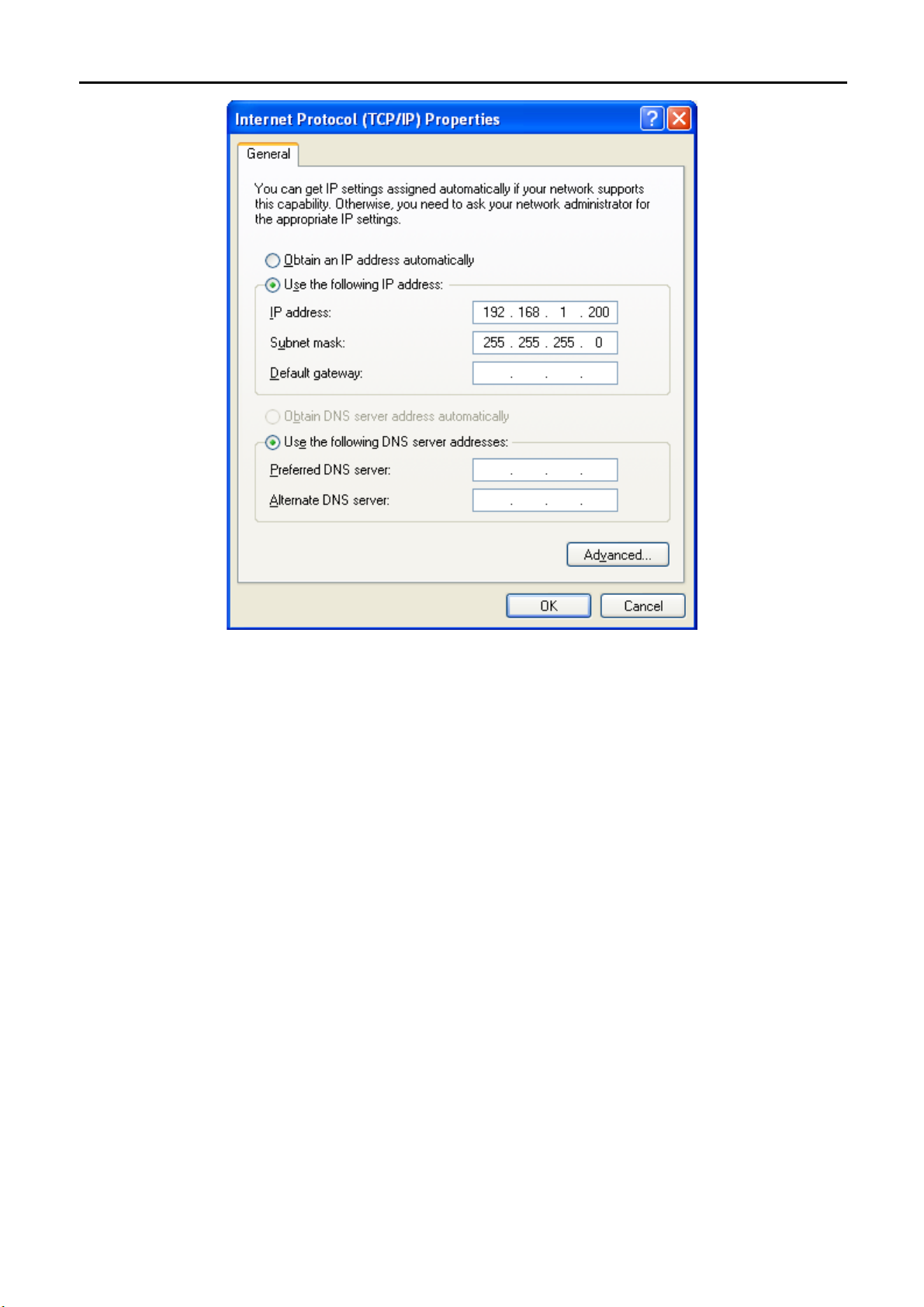
4.1.1 Configure the IP Address Manually
Summary:
Set up the TCP/IP Protocol for your PC.
Configure the network parameters. The IP address is 192.168.1.xxx ("xxx" is any number from 2 to
254), Subnet Mask is 255.255.255.0, and Gateway is 192.168.1.1 (The AP's default IP address)
1 Select Use the following IP address radio button.
2 If the AP's LAN IP address is 192.168.1.1, enter IP address 192.168.1.x (x is from 2 to 254), and Subnet
mask 255.255.255.0.
3 Select Use the following DNS server addresses radio button. In the Preferred DNS Server field, you can
enter the DNS server IP address which has been provided by your ISP
-17-
Page 26
User Manual of WNAP-7206
Figure 4-1
Now click OK to save your settings.
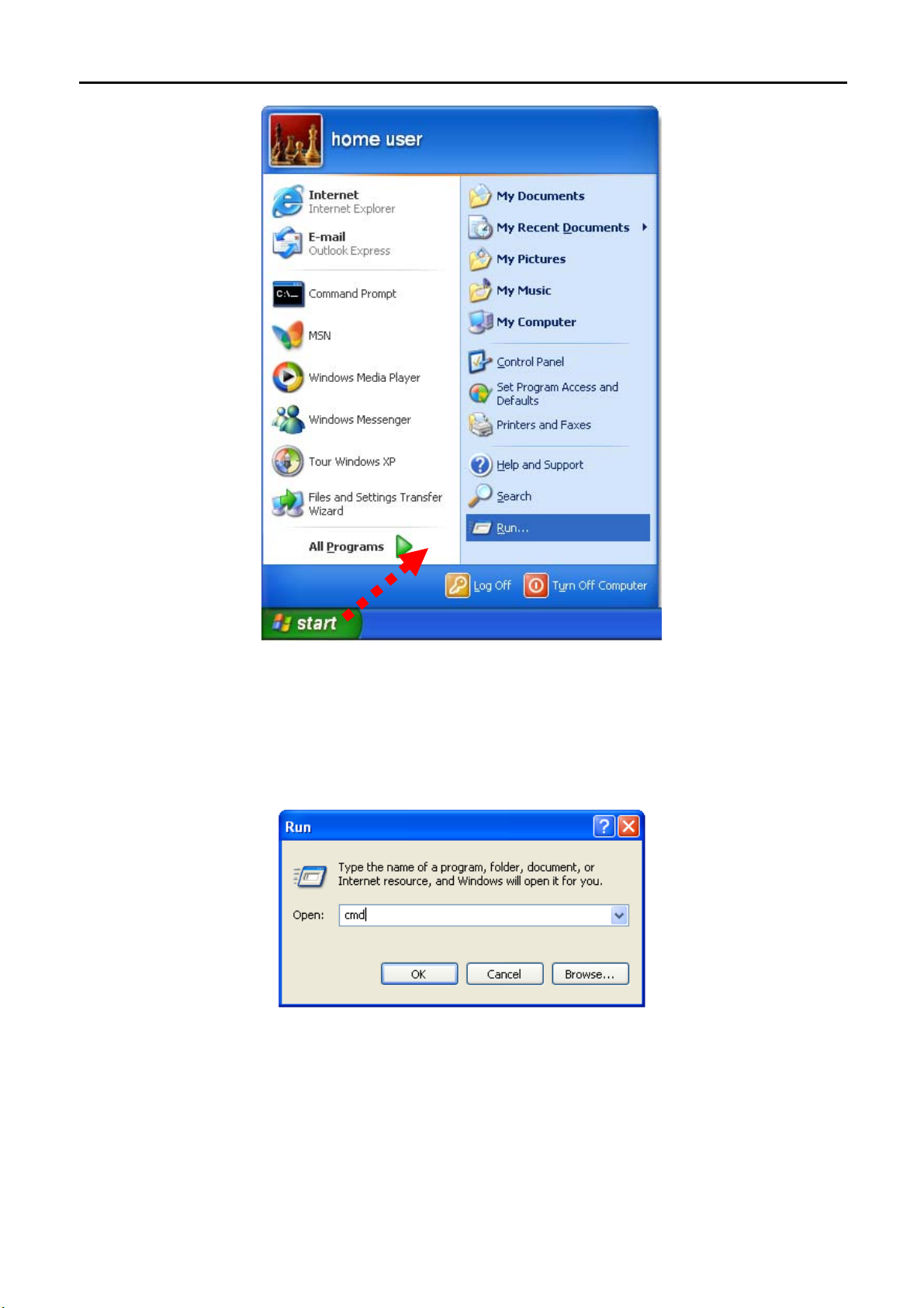
Now, you can run the Ping command in the command prompt to verify the network connection between your
PC and the AP. The following example is in Windows XP OS. Please follow the steps below:
1. Click on Start > Run.
-18-
Page 27
User Manual of WNAP-7206
2. In the run b
prompt.
Figure 4-2
ox type “cmd” and click OK. (Windows Vista users type “cmd” in the Start .Search box.)At the
Figure 4-3
Open a command prompt, and type ping 192.168.1.1, and then press Enter.
If the result displayed is similar to Figure 4-4, it means the connection between your PC and the AP
has been established well.
-19-
Page 28
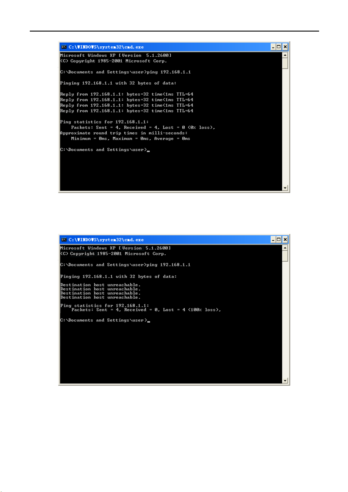
User Manual of WNAP-7206
Figure 4-4 Success result of Ping command
If the result displayed is similar to Figure 4-5, it means the connection between your PC and the AP
has failed.
Figure 4-5 Failure result of Ping command
If the address is 0.0.0.0, check your adapter installation, security settings, and the settings on your AP. Some
firewall software programs may block a DHCP request on newly installed adapters.
-20-
Page 29
User Manual of WNAP-7206
4.2 Starting Setup in the Web UI
It is easy to configure and manage the WNAP-7206 with the web browser.
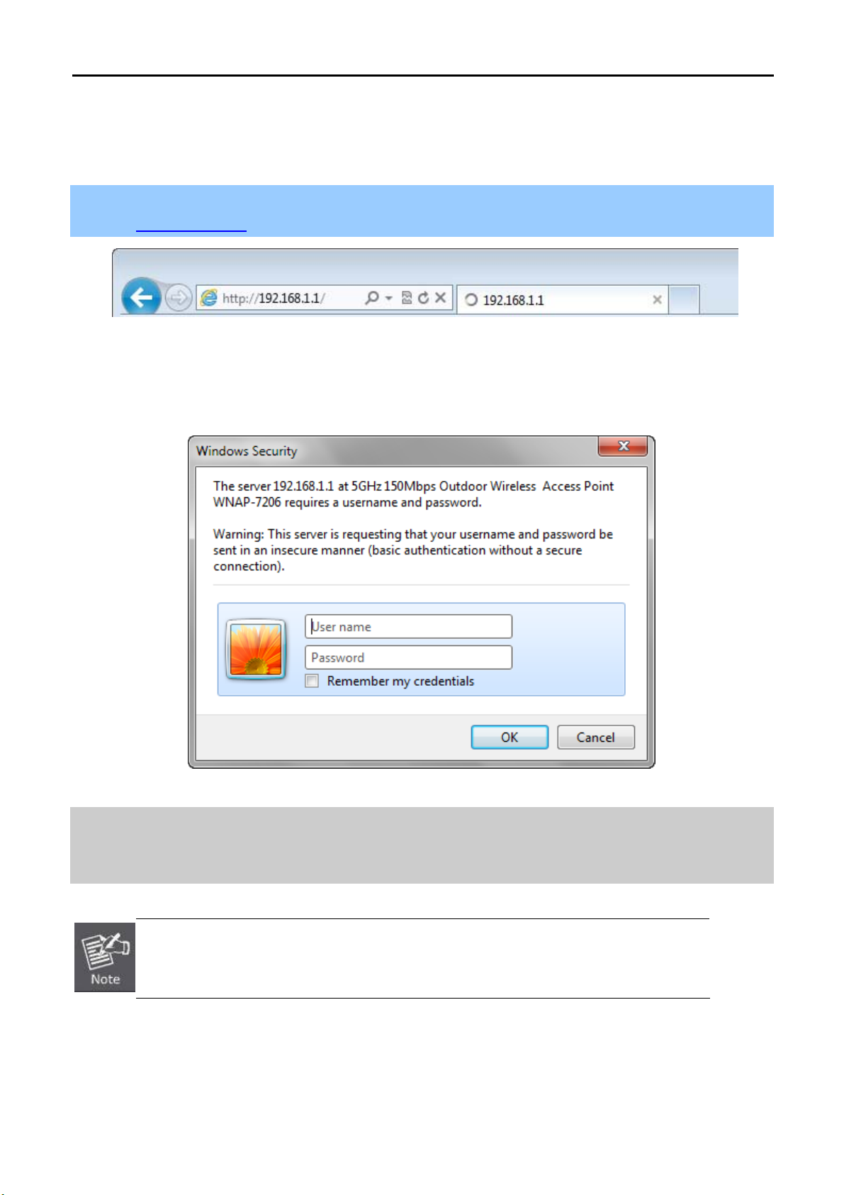
Step 1. To access the configuration page, open a web-browser and enter the default IP address
http://192.168.1.1 in the web address field of the browser.
Figure 4-6 Login the AP
After a moment, a login window will appear. Enter admin for the User Name and Password, both in lower case
letters. Then click the OK button or press the Enter key.
Figure 4-7 Login Window
Default IP Address: 192.168.1.1
Default User name: admin
Default Password: admin
If the above screen does not pop up, it may mean that your web-browser has been set to a
proxy. Go to Tools menu>Internet Options>Connections>LAN Settings, in the screen
that appears, cancel the Using Proxy checkbox, and click OK to finish it.
After entering the username and password, the Welcome message screen appears as Figure 4-8.
Check “I agree to these terms of use” and click Login button to login WNAP-7206.
-21-
Page 30
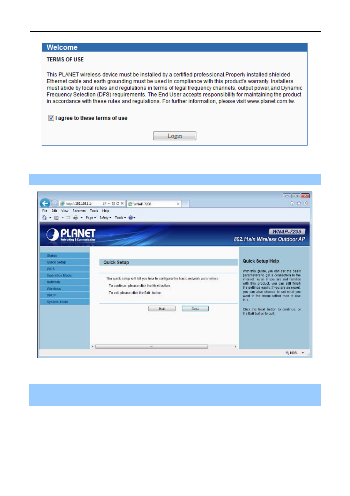
Figure 4-8 WNAP-7206 Login Welcome Screen
Step 2. The Quick Setup page appears as Figure 4-9.
User Manual of WNAP-7206
Figure 4-9 WNAP-7206 Web UI Screenshot
Step 3. Click Next to choose an Operation Mode. The default is “Standard AP” Mode. Please refer to the
instructions in the next chapter for configuring the other Operation Modes.
-22-
Page 31

User Manual of WNAP-7206
Figure 4-10 Choose Operation Mode
Step 4. Please enter the SSID, configure your Encryption Settings, Pre-Shared Key and etc. Then click Next
button to make the configuration take effect immediately.
Figure 4-11 Configure Wireless Settings
-23-
Page 32

User Manual of WNAP-7206
Step 5. Click Finish button to complete the configuration, or click Back to re-configure the setting.
h
Figure 4-12 Finis
Settings
-24-
Page 33

User Manual of WNAP-7206
Chapter 5. Configuring the AP
This chapter delivers a detailed presentation of AP’s functionalities and features allowing you to manage the AP
with ease.
5.1 Status
In this page, you can view information about the current running status of WNAP-7206, including WAN interface,
LAN interface, Wireless interface, and firmware version information.
Figure 5-1-1 Status
-25-
Page 34

User Manual of WNAP-7206
Figure 5-1-2 Status
This section allows you to view the AP’s System info listed below:
Object Description
Firmware Version
Hardware Version
The current firmware version of the AP.
The current hardware version of the AP.
LAN
MAC Address
IP Address
Subnet Mask
The physical address of the system, as seen from the LAN.
The IP address of the wired LAN.
The subnet mask associated with IP address.
Wireless
Indicates whether the wireless radio feature of the Device is
Wireless Radio
enabled or disabled.
The current wireless AP mode which the AP works on.
Wireless AP Mode
Name (SSID)
This field is only available in AP Router Mode.
The SSID of the Device.
Channel
Mode
Max Tx Rate
MAC Address
Client Status
The current wireless channel in use.
The current wireless mode which the AP works on.
The maximum Transmitting Rate.
The physical address of the AP, as seen from the WLAN.
The status of client. This field is only available in AP Client
Mode.
Init: Connection is down;
Scan: Try to find the AP;
-26-
Page 35

WDS Status
WAN
User Manual of WNAP-7206
Auth: Try to authenticate;
ASSOC: Try to associate;
Run: Associated successfully.
The status of WDS. This field is only available in AP Router
Mode.
MAC Address
IP Address
Subnet Mask
Default Gateway
DNS Server
The physical address of the WAN port, as seen from the
Internet.
The current WAN (Internet) IP Address. This field will be blank
or 0.0.0.0 if the IP Address is assigned dynamically and there
is no connection to Internet.
The subnet mask associated with the WAN IP Address.
The Gateway currently used by the Device is shown here.
When you use Dynamic IP as the connection Internet type, the
Renew button will be displayed here. Click the Renew button
to obtain new IP parameters dynamically from the ISP. And if
you have got an IP address, Release button will be displayed
here. Click the Release button to release the IP address the
Device has obtained from the ISP.
The DNS (Domain Name System) Server IP addresses
currently used by the Device. Multiple DNS IP settings are
common. Usually, the first available DNS Server is used.
Online Time
Traffic Statistics
Sent (Bytes)
Sent (Packets)
Received (Bytes)
Received (Packets)
System Up Time
The time that you are online. When you use PPPoE as WAN
connection type, the online time is displayed here. Click the
Connect or Disconnect button to connect to or disconnect from
Internet.
Traffic that counted in bytes has been sent out from the current
interface.
Traffic that counted in packets has been sent out from the
current interface.
Traffic that counted in bytes has been received from the
current interface.
Traffic that counted in packets has been received from the
current interface.
The length of the time since the Device was last powered on
or reset. Click the Refresh button to get the latest status and
settings of the Device.
-27-
Page 36

User Manual of WNAP-7206
5.2 Quick Setup
The Quick Setup helps you configure the basic functions of your Wireless AP within minutes.
Please refer to the Step 2 in the section “4.2 Starting Setup in the Web UI
Figure 5-2-1 Quick Setup
” for the detail procedure.
5.3 WPS
WPS (Wi-Fi Protected Setup) makes it easy for users who know little of wireless security to establish a secure
wireless home network, as well as to add new devices to an existing network without entering long passphrases
or configuring complicated settings.
Simply enter a PIN code or press the software PBC button or hardware WPS button (if any) and a secure
wireless connection is established.
The WPS function is only available when the Operation Mode is set to Access
Point and Multi-SSID.
The hardware WPS button is not supported in WNAP-7206.
Select menu WPS, you will see the next screen as shown in Figure 5-3-1.
Figure 5-3-1 WPS
-28-
Page 37

The page includes the following fields:
Object Description
User Manual of WNAP-7206
WPS Status
Current PIN
Add A New Device
The WPS function cannot be configured if the Wireless Function of the Device is
disabled. Please make sure the Wireless Function is enabled before configuring
the WPS.
Enable or disable the WPS function here.
The current value of the Device's PIN displayed here. The
default PIN of the Device can be found in the label or User
Guide.
Restore PIN - Restore the PIN of the Device to its default.
Gen New PIN - Click this button, and then you can get a
new random value for the Device's PIN. You can ensure
the network security by generating a new PIN.
You can add the new device to the existing network manually
by clicking Add Device button.
To add a new device:
1. If the new device supports Wi-Fi Protected Setup and is equipped with a configuration button, you can add it
to the network by pressing the configuration button on the device.
2. If the new device supports Wi-Fi Protected Setup and the connection way using PIN, you can add it to the
network by entering the Device's PIN.
For the configuration of the new device, here takes the Planet Wireless Adapter “WDL-U700” for example.
The WNAP-7206 is configured to “Standard AP” Mode.
5.3.1 Push Button Config (PBC)
This is the easiest way to establish secure connection by WPS, but if there’re more than one WPS-supported
access point using Push-Button config, please use PIN / numeric code instead.
a. To use the PBC method, select “Press the button of the new device in two minutes” in the AP.
-29-
Page 38

User Manual of WNAP-7206
Figure 5-3-1-1 PBC
b. Click Connect to start the process.
c. At the same time (within 120 seconds) in the wireless adapter, select “Push-Button” in the Add WPS
Profile. Then, click the right arrow to go next step.
Figure 5-3-1-2 Client - WPS
d. Click “Start PBC” to start the WPS process.
Figure 5-3-1-3 Client – Start PBC
-30-
Page 39

Figure 5-3-1-4
User Manual of WNAP-7206
Figure 5-3-1-5
e. Once connected, your WPS profile appears in the Profile List screen of Wireless Adapter, and the “Connect
Successfully!” message appears in the WNAP-7206.
Figure 5-3-1-6 Client – Profile List
-31-
Page 40

Figure 5-3-1-6 AP – PBC Connect Successfully
5.3.2 PIN Input Config (PIN)
User Manual of WNAP-7206
If the device supports Wi-Fi Protected Setup and the PIN method, you can add it to the network by PIN in the
following two methods.
Method One: Enter the PIN into my AP
a. To use the PIN method, select “PIN” and, in the “WPS AP List” field, select the name of the network to which
you connecting. Click the right arrow to save your settings.
Figure 5-3-2-1 Client – PIN
b. Record the PIN code of the Wireless Adapter.
-32-
Page 41

User Manual of WNAP-7206
Figure 5-3-2-2 Client – Type PIN in AP
c. In the AP, enter the PIN Code of the Wireless Adapter. Click Connect to start the process.
Figure 5-3-2-3 AP – Enter the new device’s PIN
d. Click Start PIN in Wireless Adapter.
Figure 5-3-2-4 Client – Start PIN
e. Once connected, your WPS profile appears in the Profile List screen of Wireless Adapter, and the “Connect
Successfully!” message appears in the WNAP-7206.
-33-
Page 42

Figure 5-3-2-5 Client – Profile List
User Manual of WNAP-7206
Figure 5-3-2-5 AP – PIN Connect Successfully
Method Two: Enter the PIN from my AP
a. Get the Current PIN code of the AP in Figure 5-3-1 (Each AP has its unique PIN code. Here takes the
default PIN code 12345670 of this AP for example).
b. In the Client, select “PIN” and, in the “WPS AP List” field, select the name of the network to which you
connecting. Click the right arrow to save your settings.
Figure 5-3-2-6 Client – PIN
-34-
Page 43

User Manual of WNAP-7206
c. In the PIN Entry Method, select “Type PIN below”, and enter the PIN Code of AP in the PIN Code field.
Figure 5-3-2-7 Client – Enter PIN Code
f. Go to next step, click Start PIN.
Figure 5-3-2-8 Client – Start PIN
d. In the AP, click Connect.
Figure 5-3-2-9 AP – PIN
e. Once connected, your WPS profile appears in the Profile List screen of Wireless Adapter, and the “Connect
Successfully!” message appears in the WNAP-7206.
-35-
Page 44

User Manual of WNAP-7206
Figure 5-3-2-10 Client – Profile List
Figure 5-3-2-11 AP – PIN Connect Successfully
5.4 Operation Mode
There are 3 operation modes (Standard AP, AP Router, AP Client Router) can be configured to meet various
applications.
Figure 5-4-1 Operation Mode
-36-
Page 45

The page includes the following fields:
Object Description
In this mode, the device enables multi-users to access, and provides
User Manual of WNAP-7206
Standard AP
six wireless modes: Access Point, Multi-SSID, Client, Repeater,
Universal Repeater, and Bridge with AP.
In this mode, the device enables multi-users to share Internet via
ADSL/Cable Modem. The wireless port share the same IP to ISP
AP Router
through Ethernet WAN port. The Wireless port acts the same as a LAN
port while at AP Router mode.
In this mode, the device enables multi-users to share Internet from
WISP. The LAN port devices share the same IP from WISP through
AP Client Router
Wireless port. While connecting to WISP, the Wireless port works as a
WAN port at AP Client Router mode. The Ethernet port acts as a LAN
port.
Be sure to click the Save button to save your settings on this page.
The Device will reboot automatically after you click the Save button.
5.5 Network
The Network option allows you to customize your local network manually by changing the default settings of the
AP.
5.5.1 LAN
Selecting Network > LAN will enable you to configure the IP parameters of LAN on the following page.
-37-
Page 46

The page includes the following fields:
Object Description
User Manual of WNAP-7206
Figure 5-5-1 LAN
MAC Address
Display the LAN port MAC address of the Wireless AP.
The Wireless AP’s LAN IP.
IP Address
The default is 192.168.1.1. You can change it according to your need.
Subnet Mask
Enter the subnet mask of the LAN IP.
5.5.2 WAN
Choose menu “Network > WAN”, and then you can configure the IP parameters of the WAN on the screen
below.
WAN Connection Types:
a. AP Router Mode
b. AP Client Router Mode
-38-
Page 47

User Manual of WNAP-7206
5.5.2.1. Dynamic IP
If your ISP provides the DHCP service, please choose Dynamic IP (DHCP) type, and the AP Router will
automatically obtain IP parameters from your ISP. You can see the page shown as the below.
The page includes the following fields:
Object Description
WAN Connection Type
IP Address
Subnet Mask
Default Gateway
Select Dynamic IP from the list.
The IP address assigned by your ISP dynamically.
The subnet mask assigned by your ISP dynamically.
The default gateway assigned dynamically by your ISP.
Click the Renew button to renew the IP parameters from your
Renew
ISP.
Click the Release button to release the IP parameters.
Release
If you get Address not found error when you access a Web
Figure 5-5-2 WAN - DHCP
-39-
Page 48

User Manual of WNAP-7206
site, it is likely that your DNS servers are set up improperly.
You should contact your ISP to get DNS server addresses.
The normal MTU (Maximum Transmission Unit) value for most
Ethernet networks is 1500 Bytes. For some ISPs you need to
MTU Size (in bytes)
Use These DNS
Servers
Primary DNS Server
Secondary DNS Server
Host Name
Get IP with Unicast
DHCP
modify the MTU. But this is rarely required, and should not be
done unless you are sure it is necessary for your ISP
connection.
If your ISP gives you one or two DNS IP addresses, select Use
These DNS Servers and enter the Primary DNS and
Secondary DNS into the correct fields. Otherwise, the DNS
servers will be assigned from ISP dynamically.
(Optional) Enter the DNS IP address in dotted-decimal notation
provided by your ISP.
(Optional) Enter another DNS IP address in dotted-decimal
notation provided by your ISP.
This option specifies the Host Name of the AP Router.
A few ISPs' DHCP servers do not support the broadcast
applications. If you can't get the IP Address normally, you can
choose Unicast. It is usually not required in generally condition.
5.5.2.2. Static IP
If your ISP provides a static or fixed IP Address, Subnet Mask, Gateway and DNS setting, select Static IP.
The Static IP settings page will appear as the figure shown as below.
-40-
Page 49

User Manual of WNAP-7206
The page includes the following fields:
Object Description
WAN Connections
Select Static (Fixed IP) from the list.
Enter the IP address in dotted-decimal notation provided by
IP Address
your ISP.
Enter the subnet Mask in dotted-decimal notation provided by
Subnet Mask
your ISP, usually is 255.255.255.0
(Optional) Enter the gateway IP address in dotted-decimal
Default Gateway
notation provided by your ISP.
The normal MTU (Maximum Transmission Unit) value for most
Ethernet networks is 1500 Bytes. For some ISPs you need to
MTU Size (in bytes)
modify the MTU. But this is rarely required, and should not be
Figure 5-5-3 WAN – Static IP
Primary DNS Server
Secondary DNS Server
done unless you are sure it is necessary for your ISP
connection.
(Optional) Enter the DNS IP address in dotted-decimal notation
provided by your ISP.
(Optional) Enter another DNS IP address in dotted-decimal
notation provided by your ISP.
-41-
Page 50

User Manual of WNAP-7206
5.5.2.3. PPPoE/Russia PPPoE
If local ISP provides a PPPoE connection, choose PPPoE (ADSL) and fill the necessary parameters below.
The page includes the following fields:
Object Description
WAN Connections
Select PPPoE/Russia PPPoE from the list.
PPPoE Connection
User Name
Password
Confirm Password
Enter the User Name and Password provided by your ISP.
These fields are case-sensitive.
Enter the same password entered above for the confirmation.
Secondary Connection
Figure 5-5-4 WAN – PPPoE
-42-
Page 51

User Manual of WNAP-7206
Disabled
Dynamic IP
Static IP (For Dual
Access/Russia PPPoE)
Wan Connection Mode
Connect on Demand
The Secondary Connection is disabled by default, so there is
PPPoE connection only. This is recommended.
Use dynamic IP address to connect to the local area network
provided by ISP.
Use static IP address to connect to the local area network
provided by ISP.
You can configure the Device to disconnect your Internet
connection after a specified period of the Internet connectivity
(Max Idle Time). If your Internet connection has been
terminated due to inactivity, Connect on Demand enables the
Device to automatically re-establish your connection when you
attempt to access the Internet again. If you wish to activate
Connect on Demand, put a check mark in the circle. If you
want your Internet connection to remain active all the time,
enter 0 in the Max Idle Time field.
Connect Automatically
Time-based
Connecting
Connect Manually
Sometimes the connection cannot be disconnected although
you specify a time to Max Idle Time (0~99 mins) because some
applications visit the Internet continually in the background.
Connect automatically after the Device is disconnected. To use
this option, click the radio button.
You can configure the Device to make it connect or disconnect
based on time. Enter the start time in HH-MM for connecting
and end time in HH-MM for disconnecting in the Period of Time
fields.
You can configure the Device to make it connect or disconnect
manually. After a specified period of inactivity (Max Idle Time),
the Device will disconnect your Internet connection, and not be
able to re-establish your connection automatically as soon as
you attempt to access the Internet again. To use this option,
click the radio button. If you want your Internet connection to
remain active all the times, enter 0 in the Max Idle Time field.
Connect
Disconnect
Save
Otherwise, enter the number in minutes that you wish to have
the Internet connecting last unless a new link is requested.
Click the Connect button to connect immediately.
Click the Disconnect button to disconnect immediately.
Click the Save button to save your settings.
-43-
Page 52

User Manual of WNAP-7206
Advanced
Click the Advanced button to set up the advanced options.
If you want to do some advanced configurations, please click the Advanced button, and then the page shown in
Figure 5-5-5 will appear.
The page includes the following fields:
Object Description
The default MTU (Maximum Transmission Unit) size is 1480
bytes, which is usually fine. For some ISPs, you need modify
MTU Size
the MTU. This should not be done unless you are sure it is
necessary for your ISP.
Service Name/AC
Name
They should not be done unless you are sure it is necessary
for your ISP.
If you know that your ISP does not automatically transmit IP
ISP Specified IP
Address
address to the Device during login, click "Use the IP Address
specified by ISP" checkbutton and enter the IP address in
dotted-decimal notation, which is provided by your ISP.
Detect Online Interval
The default value is 0. You can input the value between 0 and
Figure 5-5-5 PPPoE - Advanced
-44-
Page 53

User Manual of WNAP-7206
120. The Device will detect Access Concentrator online every
interval seconds. If the value is 0, it means not detecting.
If your ISP specifies a DNS server IP address for you, click the
Use the following DNS
Servers
Primary DNS
Secondary DNS
Save
Back
The new advanced PPPoE parameters will not take effect until you dial-up again.
checkbox, and fill the Primary DNS and Secondary DNS
blanks below. The Secondary DNS is optional. Otherwise, the
DNS servers will be assigned dynamically from ISP.
(Optional) Enter the DNS IP address in dotted-decimal notation
provided by your ISP.
(Optional) Enter another DNS IP address in dotted-decimal
notation provided by your ISP.
Click the Save button to save your settings.
Click the Back button when finished.
5.5.2.4. L2TP/Russia L2TP
If your ISP provides L2TP connection, please select L2TP. And enter the following parameters.
-45-
Page 54

User Manual of WNAP-7206
The page includes the following fields:
Object Description
WAN Connections
User Name
Password
Select L2TP/Russia L2TP from the list.
Enter the User Name and Password provided by your ISP.
These fields are case-sensitive.
Choose either one as you are given by your ISP. Click the
Dynamic IP/ Static IP
Connect button to connect immediately. Click the Disconnect
button to disconnect immediately.
Figure 5-5-6 L2TP
-46-
Page 55

User Manual of WNAP-7206
Server IP
Address/Name
IP Address
Subnet Mask
Gateway
DNS
Internet IP Address
Internet DNS
MTU Size (in bytes)
Max Idle Time
Connect on Demand
Connect Automatically
Connect Manually
Enter the Server IP address or domain name provided by your
ISP.
Enter the IP address used for dial-up. (Only can be configured
when Static IP is selected)
Enter the subnet Mask provided by your ISP. (Only can be
configured when Static IP is selected)
Enter gateway provided by your ISP. (Only can be configured
when Static IP is selected)
Enter DNS Server provided by your ISP. (Only can be
configured when Static IP is selected)
The Internet IP address assigned by L2TP server.
The Internet DNS server address assigned by L2TP server.
The default MTU (Maximum Transmission Unit) value is 1460
Bytes. For some ISPs you need to modify the MTU. But this is
rarely required, and should not be done unless you are sure it
is necessary for your ISP connection.
You can configure the Device to disconnect from your Internet
connection after a specified period of inactivity (Max Idle Time).
If you want your Internet connection to remain active at all time,
enter 0 in the Max Idle Time field. Otherwise, enter the number
of minutes you want to have elapsed before your Internet
connection terminates.
If your Internet connection has been terminated due to
inactivity, Connect on Demand enables the Device to
automatically re-establish your connection as soon as you
attempt to access the Internet again. If you wish to activate
Connect on Demand, check the radio button.
Connect automatically after the Device is disconnected. To use
this option, check the radio button.
You can configure the Device to make it connect or disconnect
manually. After a specified period of inactivity (Max Idle Time),
the Device will disconnect from your Internet connection, and
you will not be able to re-establish your connection
automatically as soon as you attempt to access the Internet
again. To use this option, check the radio button. If you want
your Internet connection to remain active at all time, enter "0"
in the Max Idle Time field. Otherwise, enter the number of
minutes that you wish to have the Internet connecting last
unless a new link is requested.
Save
Click the Save button to save your settings.
-47-
Page 56

User Manual of WNAP-7206
Sometimes the connection cannot be disconnected although you specify a time
to Max Idle Time, because some applications are visiting the Internet continually
in the background.
5.5.2.5. PPTP/Russia PPTP
If your ISP provides PPTP connection, please select PPTP. And enter the following parameters.
The page includes the following fields:
Figure 5-5-7 PPTP
-48-
Page 57

Object Description
User Manual of WNAP-7206
WAN Connections
User Name
Password
Dynamic IP/ Static IP
Server IP
Address/Name
IP Address
Subnet Mask
Gateway
DNS
Internet IP Address
Select PPTP/Russia PPTP from the list.
Enter the User Name and Password provided by your ISP.
These fields are case-sensitive.
Choose either one as you are given by your ISP. Click the
Connect button to connect immediately. Click the Disconnect
button to disconnect immediately.
Enter the Server IP address or domain name provided by your
ISP.
Enter the IP address used for dial-up. (Only can be configured
when Static IP is selected)
Enter the subnet Mask provided by your ISP. (Only can be
configured when Static IP is selected)
Enter gateway provided by your ISP. (Only can be configured
when Static IP is selected)
Enter DNS Server provided by your ISP. (Only can be
configured when Static IP is selected)
The Internet IP address assigned by PPTP server.
Internet DNS
MTU Size (in bytes)
Max Idle Time
Connect on Demand
Connect Automatically
Connect Manually
The Internet DNS server address assigned by PPTP server.
The default MTU (Maximum Transmission Unit) value is 1420
Bytes. For some ISPs you need to modify the MTU. But this is
rarely required, and should not be done unless you are sure it
is necessary for your ISP connection.
You can configure the Device to disconnect from your Internet
connection after a specified period of inactivity (Max Idle Time).
If you want your Internet connection to remain active at all time,
enter 0 in the Max Idle Time field. Otherwise, enter the number
of minutes you want to have elapsed before your Internet
connection terminates.
If your Internet connection has been terminated due to
inactivity, Connect on Demand enables the Device to
automatically re-establish your connection as soon as you
attempt to access the Internet again. If you wish to activate
Connect on Demand, check the radio button.
Connect automatically after the Device is disconnected. To use
this option, check the radio button.
You can configure the Device to make it connect or disconnect
manually. After a specified period of inactivity (Max Idle Time),
the Device will disconnect from your Internet connection, and
you will not be able to re-establish your connection
automatically as soon as you attempt to access the Internet
again. To use this option, check the radio button. If you want
-49-
Page 58

User Manual of WNAP-7206
your Internet connection to remain active at all time, enter "0"
in the Max Idle Time field. Otherwise, enter the number of
minutes that you wish to have the Internet connecting last
unless a new link is requested.
Save
Click the Save button to save your settings.
Sometimes the connection cannot be disconnected although you specify a time
to Max Idle Time, because some applications are visiting the Internet continually
in the background.
5.5.2.6. BigPond Cable
If your ISP provides BigPond Cable (or Heart Beat Signal) connection, please select BigPond Cable option.
And then you should enter the following parameters.
This type of WAN Connection is only available in AP Router mode, but not in AP Client Router Mode.
Figure 5-5-8 BigPond Cable
-50-
Page 59

The page includes the following fields:
Object Description
User Manual of WNAP-7206
WAN Connections
User Name
Password
Auth Server
Auth Domain
MTU Size (in bytes)
Connect on Demand
Select BigPond Cable from the list.
Enter the User Name and Password provided by your ISP.
These fields are case-sensitive.
Enter the authenticating server IP address or host name.
Type in the domain suffix server name based on your location.
NSW / ACT - nsw.bigpond.net.au
VIC / TAS / WA / SA / NT - vic.bigpond.net.au
QLD - qld.bigpond.net.au
The normal MTU (Maximum Transmission Unit) value for most
Ethernet networks is 1500 Bytes. It is not recommended that
you change the default MTU Size unless required by your ISP.
In this mode, the Internet connection can be terminated
automatically after a specified inactivity period (Max Idle Time)
and be re-established when you attempt to access the Internet
again. If you want your Internet connection keeps active all the
Connect Automatically
Connect Manually
Connect
Disconnect
Save
time, please enter 0 in the Max Idle Time field. Otherwise,
enter the number of minutes you want to have elapsed before
your Internet access disconnects.
Connect automatically after the Device is disconnected. To use
this option, check the radio button.
You can click the Connect/Disconnect button to
connect/disconnect immediately. This mode also supports the
Max Idle Time function as Connect on Demand mode. The
Internet connection can be disconnected automatically after a
specified inactivity period and re-established when you attempt
to access the Internet again.
Click the Connect button to connect immediately.
Click the Disconnect button to disconnect immediately.
Click the Save button to save your settings.
Sometimes the connection cannot be disconnected although you specify a time
to Max Idle Time, because some applications are visiting the Internet continually
in the background.
-51-
Page 60

User Manual of WNAP-7206
5.5.3 MAC Clone
Choose menu “Network > MAC Clone”, and then you can configure the WAN MAC Address on the screen
below, as shown in Figure 5-5-8.
Figure 5-5-8 MAC Clone
The page includes the following fields:
Object Description
This field displays the current MAC address of the WAN port. If
your ISP requires that you register the MAC address of your
adapter, please enter the correct MAC address into this field.
WAN MAC Address
Usually, you do not need to change anything here. The format
for the MAC Address is XX-XX-XX-XX-XX-XX (X is any
hexadecimal digit).
This field displays the MAC address of the PC that is managing
Your PC's MAC
Address
the Device. If the MAC address of your adapter is registered,
you can click the Clone MAC Address button, and then it will
be filled into the WAN MAC Address field.
Click Restore Factory MAC to restore the MAC address of
Restore Factory MAC
WAN port to the factory default value.
Save
Click the Save button to save your settings.
1. Only the PC(s) in your LAN can use the MAC Address Clone feature.
2. If you change WAN MAC Address when the WAN connection type is PPPoE, it
will not take effect until the connection is re-established.
-52-
Page 61

User Manual of WNAP-7206
5.6 Wireless
You could configure the minimum number of Wireless settings for communication, such as Network Name (SSID)
and Channel. The Access Point can be set simply with only the minimum setting items.
5.6.1 Wireless Settings
Choose menu “Wireless > Wireless Settings”, and then you can configure the basic settings for the wireless
network on the Wireless Settings page
The Wireless Settings page in Standard AP mode allows you to configure the wireless mode for your device.
Six operation modes are supported here, including Access Point, Multi-SSID, Client, Repeater, Universal
Repeater and Bridge with AP.
5.6.1.1. Access Point Mode
-53-
Page 62

User Manual of WNAP-7206
First at all, you should select your location, save it and reboot, or you may not
search any APs. Ensure you select a correct country to conform local law.
Incorrect settings may cause interference.
The page includes the following fields:
Object Description
Enter a string of up to 32 characters. The same Name (SSID) must be
assigned to all wireless devices in your network. The default SSID is set
SSID
to be default. But it is recommended strongly that you change your
networks name (SSID) to a different value. This value is case-sensitive.
For example, MYSSID is NOT the same as MySsid.
Select your region from the pull-down list. This field specifies the
region where the wireless function of the Device can be used. It may
Region
be illegal to use the wireless function of the Device in a region other
than one of those specified in this filed. If your country or region is not
listed, please contact your local government agency for assistance.
Figure 5-6-1-1 AP Mode
-54-
Page 63

User Manual of WNAP-7206
Transmit Power
Channel
Mode
Max Tx Rate
Enable Wireless Radio
Enable SSID Broadcast
Enable DFS
You can limit the Transmit Power of the Device through this field. You
can select one of the options listed as the below items.
This field determines which operating frequency will be used. It is not
necessary to change the wireless channel unless you notice
interference problems with another nearby access point. If you select
auto, then the Device will select the best channel automatically.
This field determines the wireless mode which the Device works on.
You can limit the maximum tx rate of the Device through this field. You
can select one of the options listed as the below items.
The wireless radio of the Device can be enabled or disabled to allow
wireless stations access. If enabled, the wireless stations will be able
to access the Device; otherwise, wireless stations will not be able to
access the Device.
If you select the Enable SSID Broadcast checkbox, the wireless
Router will broadcast its name (SSID) on the air.
Check Enable DFS to enable DFS function.
Save
5.6.1.2. Multi-SSID Mode
Click the Save button to save your settings on this page.
-55-
Page 64

User Manual of WNAP-7206
First at all, you should select your location, save it and reboot, or you may not
search any APs. Ensure you select a correct country to conform local law.
Incorrect settings may cause interference.
The page includes the following fields:
Object Description
Check this box to enable the VLAN function. The AP supports up to 4
VLANs. All wireless PCs in the VLANs are able to access this AP. The AP
Enable VLAN
can also work with an IEEE 802.1Q Tag VLAN supporting Switch. If this
Switch enables the Tag VLAN function, besides all wireless PCs, only the
PCs in the VLAN same with SSID1 are able to access the AP. If a PC is
Figure 5-6-1-2 Multi-SSID Mode
-56-
Page 65

SSID
VLAN ID
Region
User Manual of WNAP-7206
directly connected to the LAN port of the AP, please make sure that its
adapter supports Tag function, or this PC will not be able to access the
AP.
Enter a value of up to 32 characters. The same Name (SSID) must be
assigned to all wireless devices in your network. In Multi-SSID
operation mode, enter SSID for each BSS in the field "SSID1" ~
"SSID4".
The ID of a VLAN. Only in the same VLAN can a wireless PC and a
wired PC communicate with each other. The value can be between 1
and 4095. If the VLAN function is enabled, when AP forwards packets,
the packets out from the LAN port will be added with an IEEE 802.1Q
VLAN Tag, whose VLAN ID is just the ID of the VLAN where the
sender belongs.
Select your region from the pull-down list. This field specifies the
region where the wireless function of the Device can be used. It may
be illegal to use the wireless function of the Device in a region other
than one of those specified in this filed. If your country or region is not
listed, please contact your local government agency for assistance.
Transmit Power
Channel
Mode
Max Tx Rate
Enable Wireless Radio
Enable SSID Broadcast
Enable DFS
You can limit the Transmit Power of the Device through this field. You
can select one of the options listed as the below items.
This field determines which operating frequency will be used. It is not
necessary to change the wireless channel unless you notice
interference problems with another nearby access point. If you select
auto, then the Device will select the best channel automatically.
This field determines the wireless mode which the Device works on.
You can limit the maximum tx rate of the Device through this field. You
can select one of the options listed as the below items.
The wireless radio of the Device can be enabled or disabled to allow
wireless stations access. If enabled, the wireless stations will be able
to access the Device; otherwise, wireless stations will not be able to
access the Device.
If you select the Enable SSID Broadcast checkbox, the wireless
Router will broadcast its name (SSID) on the air.
Check Enable DFS to enable DFS function.
Save
Click the Save button to save your settings on this page.
-57-
Page 66

5.6.1.3. Client Mode (Client Bridge)
User Manual of WNAP-7206
Figure 5-6-1-3 Client Mode
First at all, you should select your location, save it and reboot, or you may not
search any APs. Ensure you select a correct country to conform local law.
Incorrect settings may cause interference.
-58-
Page 67

The page includes the following fields:
Object Description
The AP client can connect to AP with WDS enabled or disabled. If
WDS is enabled, all traffic from wired networks will be forwarded in the
Enable WDS
format of WDS frames consisting of four address fields. If WDS is
disabled, three address frames are used. If your AP supports WDS
well, please enable this option.
The SSID of the AP your Device is going to connect to as a client. You
can also use the search function to select a SSID to join.
SSID
If you know the SSID of the desired AP, you can also input it to the
field "SSID" manually.
The BSSID of the AP your Device is going to connect to as a client.
MAC of AP
You can also use the search function to select a BSSID to join.
Select your region from the pull-down list. This field specifies the
region where the wireless function of the Device can be used. It may
Region
be illegal to use the wireless function of the Device in a region other
than one of those specified in this filed. If your country or region is not
listed, please contact your local government agency for assistance.
You can limit the Transmit Power of the Device through this field. You
Transmit Power
can select one of the options listed as the below items.
The wireless radio of the Device can be enabled or disabled to allow
wireless stations access. If enabled, the wireless stations will be able
Enable Wireless Radio
to access the Device; otherwise, wireless stations will not be able to
access the Device.
User Manual of WNAP-7206
Enable DFS
Check Enable DFS to enable DFS function.
Click this button; you can search the AP which runs in the current
Search
Save
channel.
Click the Save button to save your settings on this page.
To establish connection with remote AP, please follow the instructions as below:
1. Click Search button.
-59-
Page 68

User Manual of WNAP-7206
2. In the AP List, select the AP you want to access, and click Connect.
3. The target network’s SSID will be automatically filled into the SSID field. Click Save to apply the setting.
-60-
Page 69

The operating distance or range of your wireless connection varies significantly
A
based on the physical placement of the Device. For best results, place your
Device:
Near the center of the area in which your wireless stations will operate;
In an elevated location such as a high shelf;
way from the potential sources of interference, such as PCs, microwaves,
and cordless phones;
With the Antenna in the upright position;
Away from large metal surfaces.
5.6.1.4. Repeater Mode
User Manual of WNAP-7206
-61-
Page 70

User Manual of WNAP-7206
First at all, you should select your location, save it and reboot, or you may not
search any APs. Ensure you select a correct country to conform local law.
Incorrect settings may cause interference.
The page includes the following fields:
Object Description
The BSSID of the AP your Device is going to connect to as a client.
MAC of AP
You can also use the search function to select a BSSID to join.
Select your region from the pull-down list. This field specifies the
region where the wireless function of the Device can be used. It may
Region
be illegal to use the wireless function of the Device in a region other
than one of those specified in this filed. If your country or region is not
listed, please contact your local government agency for assistance.
You can limit the Transmit Power of the Device through this field. You
Transmit Power
can select one of the options listed as the below items.
Figure 5-6-1-4 Repeater Mode
Max Tx Rate
Enable Wireless Radio
You can limit the maximum tx rate of the Device through this field. You
can select one of the options listed as the below items.
The wireless radio of the Device can be enabled or disabled to allow
wireless stations access. If enabled, the wireless stations will be able
-62-
Page 71

User Manual of WNAP-7206
to access the Device; otherwise, wireless stations will not be able to
access the Device.
Enable DFS
Check Enable DFS to enable DFS function.
Click this button; you can search the AP which runs in the current
Search
Save
channel.
Click the Save button to save your settings on this page.
5.6.1.5. Universal Repeater Mode
-63-
Page 72

User Manual of WNAP-7206
Figure 5-6-1-5 Universal Repeater Mode
First at all, you should select your location, save it and reboot, or you may not
search any APs. Ensure you select a correct country to conform local law.
Incorrect settings may cause interference.
The page includes the following fields:
Object Description
The BSSID of the AP your Device is going to connect to as a client.
MAC of AP
You can also use the search function to select a BSSID to join.
Select your region from the pull-down list. This field specifies the
region where the wireless function of the Device can be used. It may
Region
be illegal to use the wireless function of the Device in a region other
than one of those specified in this filed. If your country or region is not
listed, please contact your local government agency for assistance.
You can limit the Transmit Power of the Device through this field. You
Transmit Power
can select one of the options listed as the below items.
Max Tx Rate
Enable Wireless Radio
You can limit the maximum tx rate of the Device through this field. You
can select one of the options listed as the below items.
The wireless radio of the Device can be enabled or disabled to allow
wireless stations access. If enabled, the wireless stations will be able
to access the Device; otherwise, wireless stations will not be able to
-64-
Page 73

access the Device.
User Manual of WNAP-7206
Enable DFS
Check Enable DFS to enable DFS function.
Click this button; you can search the AP which runs in the current
Search
Save
channel.
Click the Save button to save your settings on this page.
5.6.1.6. Bridge with AP Mode (PtP & PtMP)
In this mode, you can establish Point to Point (PtP) connection or Point to Multi-Point (PtMP) connection.
-65-
Page 74

User Manual of WNAP-7206
First at all, you should select your location, save it and reboot, or you may not
search any APs. Ensure you select a correct country to conform local law.
Incorrect settings may cause interference.
The page includes the following fields:
Object Description
Enter a value of up to 32 characters. The same Name (SSID) must be
assigned to all wireless devices in your network. In Multi-SSID
SSID
operation mode, enter SSID for each BSS in the field "SSID1" ~
"SSID4".
Select your region from the pull-down list. This field specifies the
Region
region where the wireless function of the Device can be used. It may
Figure 5-6-1-6 Bridge with AP Mode
-66-
Page 75

User Manual of WNAP-7206
be illegal to use the wireless function of the Device in a region other
than one of those specified in this filed. If your country or region is not
listed, please contact your local government agency for assistance.
Transmit Power
Channel
Mode
Max Tx Rate
Enable Wireless Radio
Enable SSID Broadcast
MAC of AP1~4
You can limit the Transmit Power of the Device through this field. You
can select one of the options listed as the below items.
This field determines which operating frequency will be used. It is not
necessary to change the wireless channel unless you notice
interference problems with another nearby access point. If you select
auto, then the Device will select the best channel automatically.
This field determines the wireless mode which the Device works on.
You can limit the maximum tx rate of the Device through this field. You
can select one of the options listed as the below items.
The wireless radio of the Device can be enabled or disabled to allow
wireless stations access. If enabled, the wireless stations will be able
to access the Device; otherwise, wireless stations will not be able to
access the Device.
If you select the Enable SSID Broadcast checkbox, the wireless
Router will broadcast its name (SSID) on the air.
Enter the MAC address of AP that you want to access. If you select the
radio button before MAC of AP, the AP client will connect to AP
according to MAC address.
Enable DFS
Search
Save
Check Enable DFS to enable DFS function.
Click this button; you can search the AP which runs in the current
channel.
Click the Save button to save your settings on this page.
-67-
Page 76

5.6.1.7. AP Router Mode
User Manual of WNAP-7206
First at all, you should select your location, save it and reboot, or you may not
search any APs. Ensure you select a correct country to conform local law.
Incorrect settings may cause interference.
The page includes the following fields:
Figure 5-6-1-7 AP Router Mode
-68-
Page 77

SSID
Region
User Manual of WNAP-7206
Object Description
Enter a string of up to 32 characters. The same Name (SSID) must be
assigned to all wireless devices in your network. The default SSID is set
to be default. But it is recommended strongly that you change your
networks name (SSID) to a different value. This value is case-sensitive.
For example, MYSSID is NOT the same as MySsid.
Select your region from the pull-down list. This field specifies the
region where the wireless function of the Device can be used. It may
be illegal to use the wireless function of the Device in a region other
than one of those specified in this filed. If your country or region is not
listed, please contact your local government agency for assistance.
Transmit Power
Channel
Mode
Max Tx Rate
Enable DFS
Enable Wireless Radio
Enable SSID Broadcast
You can limit the Transmit Power of the Device through this field. You
can select one of the options listed as the below items.
This field determines which operating frequency will be used. It is not
necessary to change the wireless channel unless you notice
interference problems with another nearby access point. If you select
auto, then the Device will select the best channel automatically.
This field determines the wireless mode which the Device works on.
You can limit the maximum tx rate of the Device through this field. You
can select one of the options listed as the below items.
Check Enable DFS to enable DFS function.
The wireless radio of the Device can be enabled or disabled to allow
wireless stations access. If enabled, the wireless stations will be able
to access the Device; otherwise, wireless stations will not be able to
access the Device.
If you select the Enable SSID Broadcast checkbox, the wireless
Router will broadcast its name (SSID) on the air.
Enable WDS
Save
If you select the Enable WDS checkbox, the wireless Router will
broadcast its name (SSID) on the air.
Click the Save button to save your settings on this page.
-69-
Page 78

5.6.1.8. AP Client Router Mode (WISP+AP)
User Manual of WNAP-7206
-70-
Page 79

User Manual of WNAP-7206
Figure 5-6-1-8 AP Client Router Mode
First at all, you should select your location, save it and reboot, or you may not
search any APs. Ensure you select a correct country to conform local law.
Incorrect settings may cause interference.
The page includes the following fields:
Object Description
The SSID of the AP your Device is going to connect to as a client. You
can also use the search function to select a SSID to join.
SSID
If you know the SSID of the desired AP, you can also input it to the
field "SSID" manually.
-71-
Page 80

User Manual of WNAP-7206
BSSID
Region
Transmit Power
Enable DFS
Search
Key type
WEP Index
Auth Type
Password
Local SSID
Enable Wireless Router
Radio
The BSSID of the AP your Device is going to connect to as a client.
You can also use the search function to select a BSSID to join.
Select your region from the pull-down list. This field specifies the
region where the wireless function of the Device can be used. It may
be illegal to use the wireless function of the Device in a region other
than one of those specified in this filed. If your country or region is not
listed, please contact your local government agency for assistance.
You can limit the Transmit Power of the Device through this field. You
can select one of the options listed as the below items.
Check Enable DFS to enable DFS function.
Click this button; you can search the AP which runs in the current
channel.
This option should be chosen according to the AP's security
configuration. It is recommended that the security type is the same as
your AP's security type.
This option should be chosen if the key type is WEP (ASCII) or WEP
(HEX). It indicates the index of the WEP key.
This option should be chosen if the key type is WEP (ASCII) or WEP
(HEX). It indicates the authorization type of the Root AP.
If the AP your Device is going to connect needs password, you need to
fill the password in this blank.
Enter a value of up to 32 characters. The same Name (SSID) must be
assigned to all wireless devices in your network.
The wireless radio of the Device can be enabled or disabled to allow
wireless stations access. If enabled, the wireless stations will be able
to access the Device; otherwise, wireless stations will not be able to
access the Device.
Enable SSID Broadcast
Router will broadcast its name (SSID) on the air.
If you select the Disable Local Wireless Access checkbox, the
If you select the Enable SSID Broadcast checkbox, the wireless
Disable Local Wireless
Access
Save
wireless Device will disable local wireless access; other stations will
not be able to access the Device by wireless.
Click the Save button to save your settings on this page.
To establish connection with remote AP, please follow the instructions as below:
1. Click Search button.
-72-
Page 81

2. In the AP List, select the AP you want to access, and click Connect.
User Manual of WNAP-7206
3. The target network’s SSID will be automatically filled into the SSID field. Click Save to apply the setting.
The operating distance or range of your wireless connection varies significantly
based on the physical placement of the Device. For best results, place your
Device:
Near the center of the area in which your wireless stations will operate;
In an elevated location such as a high shelf;
-73-
Page 82

User Manual of WNAP-7206
Away from the potential sources of interference, such as PCs, microwaves,
and cordless phones;
With the Antenna in the upright position;
Away from large metal surfaces.
5.6.2 Wireless Security
Choose menu “Wireless > Wireless Security”, and then you can configure the security settings of your wireless
network.
There are three wireless security modes supported by the Device: WEP (Wired Equivalent Privacy), WPA/WPA2
(Wi-Fi Protected Access/ Wi-Fi Protected Access 2), and WPA-PSK/WPA2-PSK (Pre-Shared Key). The security
options are different for different operation mode.
Only in Standard AP mode, the current operation mode is shown at the top.
Besides, if Multi-SSID, a sub mode of Standard AP, is selected, you can choose
one of the 4 SSIDs from the pull-down list.
-74-
Page 83

5.6.2.1. Operation Mode – Access Point
User Manual of WNAP-7206
Object Description
Disable Security
WEP
WPA/WPA2
WPA-PSK/WPA2-PSK
Figure 5-6-2-1 Wireless Security - AP
The wireless security function can be enabled or disabled. If disabled,
the wireless stations will be able to connect the AP without encryption.
It is recommended strongly that you choose one of following options to
enable security.
Select 802.11 WEP security.
Select WPA based on Radius Server.
Select WPA based on pre-shared passphrase.
-75-
Page 84

User Manual of WNAP-7206
Each security option has its own settings as described follows:
WEP
WEP is intended to provide data confidentiality comparable to that of a traditional wired network. Two methods of
authentication can be used with WEP: Open System authentication and Shared Key authentication.
Object Description
You can select one of following types:
Automatic - Select Shared Key or Open System
Type
WEP Key Format
WEP Key settings
Key Type
You can select ASCII or Hexadecimal format. ASCII Format stands
for any combination of keyboard characters in the specified length.
Hexadecimal format stands for any combination of hexadecimal digits
(0-9, a-f, A-F) in the specified length.
Select which of the four keys will be used and enter the matching WEP
key information for your network in the selected key radio button.
These values must be identical on all wireless stations in your network.
You can select the WEP key length (64-bit, or 128-bit, or 152-bit) for
encryption. "Disabled" means this WEP key entry is invalid.
For 64-bit encryption - You can enter 10 hexadecimal digits (any
combination of 0-9, a-f, A-F, and null key is not permitted) or 5 ASCII
characters.
For 128-bit encryption - You can enter 26 hexadecimal digits (any
combination of 0-9, a-f, A-F, and null key is not permitted) or 13 ASCII
characters.
For 152-bit encryption - You can enter 32 hexadecimal digits (any
combination of 0-9, a-f, A-F, and null key is not permitted) or 16 ASCII
characters.
authentication type automatically based on the wireless
station's capability and request.
Shared Key - Select 802.11 Shared Key authentication.
Open System - Select 802.11 Open System authentication.
If you do not set the key, the wireless security function is still disabled even if you
have selected Shared Key as Authentication Type.
WPA/WPA2
Object Description
Version
You can select one of following versions:
Automatic - Select WPA or WPA2 automatically based on the
wireless station's capability and request.
-76-
Page 85

WPA - Wi-Fi Protected Access.
WPA2 - WPA version 2.
User Manual of WNAP-7206
Encryption
Radius Server IP
Radius Port
Radius Password
Group Key Update
Period
You can select either Automatic, or TKIP or AES.
Enter the IP address of the Radius Server.
Enter the port that radius service uses.
Enter the password for the Radius Server.
Specify the group key update interval in seconds. The value can be
either 0 or at least 30. Enter 0 to disable the update.
WPA-PSK/WPA2-PSK
The later WPA2 protocol features compliance with the full IEEE 802.11i standard and uses Advanced
Encryption Standard (AES) in addition to TKIP encryption protocol to guarantee better security than that
provided by WEP or WPA.
Object Description
You can select one of following versions:
Automatic - Select WPA-PSK or WPA2-PSK automatically based
Version
Encryption
PSK Password
Group Key Update
Period
on the wireless station's capability and request.
WPA-PSK - Pre-shared key of WPA.
WPA2-PSK - Pre-shared key of WPA2.
You can select either Automatic, or TKIP or AES.
You can enter ASCII or Hexadecimal characters. For Hexadecimal, the
length should be between 8 and 64 characters; for ASCII, the length
should be between 8 and 63 characters.
Specify the group key update interval in seconds. The value can be
either 0 or at least 30. Enter 0 to disable the update.
-77-
Page 86

5.6.2.2. Operation Mode – Multi-SSID
User Manual of WNAP-7206
Figure 5-6-2-2 Wireless Security – Multi-SSID
Object Description
The wireless security function can be enabled or disabled. If disabled,
the wireless stations will be able to connect the AP without encryption.
Disable Security
It is recommended strongly that you choose one of following options to
enable security.
WPA/WPA2
WPA-PSK/WPA2-PSK
Select WPA based on Radius Server.
Select WPA based on pre-shared passphrase.
Each security option has its own settings as described follows:
WPA/WPA2
Object Description
You can select one of following versions:
Version
Automatic - Select WPA or WPA2 automatically based on the
wireless station's capability and request.
-78-
Page 87

WPA - Wi-Fi Protected Access.
WPA2 - WPA version 2.
User Manual of WNAP-7206
Encryption
Radius Server IP
Radius Port
Radius Password
Group Key Update
Period
You can select either Automatic, or TKIP or AES.
Enter the IP address of the Radius Server.
Enter the port that radius service uses.
Enter the password for the Radius Server.
Specify the group key update interval in seconds. The value can be
either 0 or at least 30. Enter 0 to disable the update.
This security option will become unavailable, if the Enable VLAN in Wireless
Settings under Multi-SSID mode.
WPA-PSK/WPA2-PSK
The later WPA2 protocol features compliance with the full IEEE 802.11i standard and uses Advanced
Encryption Standard (AES) in addition to TKIP encryption protocol to guarantee better security than that
provided by WEP or WPA.
Object Description
You can select one of following versions:
Automatic - Select WPA-PSK or WPA2-PSK automatically based
Version
WPA-PSK - Pre-shared key of WPA.
WPA2-PSK - Pre-shared key of WPA2.
Encryption
You can select either Automatic, or TKIP or AES.
You can enter ASCII or Hexadecimal characters. For Hexadecimal, the
PSK Password
length should be between 8 and 64 characters; for ASCII, the length
should be between 8 and 63 characters.
Group Key Update
Period
Specify the group key update interval in seconds. The value can be
either 0 or at least 30. Enter 0 to disable the update.
on the wireless station's capability and request.
-79-
Page 88

5.6.2.3. Operation Mode – Client
User Manual of WNAP-7206
Figure 5-6-2-3 Wireless Security - Client
Object Description
The wireless security function can be enabled or disabled. If disabled,
the wireless stations will be able to connect the AP without encryption.
Disable Security
It is recommended strongly that you choose one of following options to
enable security.
WEP
WPA-PSK/WPA2-PSK
Select 802.11 WEP security.
Select WPA based on pre-shared passphrase.
Each security option has its own settings as described follows:
WEP
WEP is intended to provide data confidentiality comparable to that of a traditional wired network. Two methods of
authentication can be used with WEP: Open System authentication and Shared Key authentication.
Type
Object Description
You can select one of following types:
-80-
Page 89

WEP Key Format
WEP Key settings
Key Type
User Manual of WNAP-7206
Automatic - Select Shared Key or Open System
authentication type automatically based on the wireless
station's capability and request.
Shared Key - Select 802.11 Shared Key authentication.
Open System - Select 802.11 Open System authentication.
You can select ASCII or Hexadecimal format. ASCII Format stands
for any combination of keyboard characters in the specified length.
Hexadecimal format stands for any combination of hexadecimal digits
(0-9, a-f, A-F) in the specified length.
Select which of the four keys will be used and enter the matching WEP
key information for your network in the selected key radio button.
These values must be identical on all wireless stations in your network.
You can select the WEP key length (64-bit, or 128-bit, or 152-bit) for
encryption. "Disabled" means this WEP key entry is invalid.
For 64-bit encryption - You can enter 10 hexadecimal digits (any
combination of 0-9, a-f, A-F, and null key is not permitted) or 5 ASCII
characters.
For 128-bit encryption - You can enter 26 hexadecimal digits (any
combination of 0-9, a-f, A-F, and null key is not permitted) or 13 ASCII
characters.
For 152-bit encryption - You can enter 32 hexadecimal digits (any
combination of 0-9, a-f, A-F, and null key is not permitted) or 16 ASCII
characters.
If you do not set the key, the wireless security function is still disabled even if you
have selected Shared Key as Authentication Type.
WPA-PSK/WPA2-PSK
The later WPA2 protocol features compliance with the full IEEE 802.11i standard and uses Advanced
Encryption Standard (AES) in addition to TKIP encryption protocol to guarantee better security than that
provided by WEP or WPA.
Object Description
You can select one of following versions:
Automatic - Select WPA-PSK or WPA2-PSK automatically based
Version
on the wireless station's capability and request.
WPA-PSK - Pre-shared key of WPA.
Encryption
WPA2-PSK - Pre-shared key of WPA2.
You can select either Automatic, or TKIP or AES.
-81-
Page 90

User Manual of WNAP-7206
You can enter ASCII or Hexadecimal characters. For Hexadecimal, the
PSK Password
length should be between 8 and 64 characters; for ASCII, the length
should be between 8 and 63 characters.
Group Key Update
Period
Specify the group key update interval in seconds. The value can be
either 0 or at least 30. Enter 0 to disable the update.
5.6.2.4. Operation Mode – Repeater
Object Description
Disable Security
WEP
WPA-PSK/WPA2-PSK
Figure 5-6-2-4 Wireless Security - Repeater
The wireless security function can be enabled or disabled. If disabled,
the wireless stations will be able to connect the AP without encryption.
It is recommended strongly that you choose one of following options to
enable security.
Select 802.11 WEP security.
Select WPA based on pre-shared passphrase.
-82-
Page 91

User Manual of WNAP-7206
Each security option has its own settings as described follows:
WEP
WEP is intended to provide data confidentiality comparable to that of a traditional wired network. Two methods of
authentication can be used with WEP: Open System authentication and Shared Key authentication.
Object Description
You can select one of following types:
Automatic - Select Shared Key or Open System
Type
WEP Key Format
WEP Key settings
Key Type
You can select ASCII or Hexadecimal format. ASCII Format stands
for any combination of keyboard characters in the specified length.
Hexadecimal format stands for any combination of hexadecimal digits
(0-9, a-f, A-F) in the specified length.
Select which of the four keys will be used and enter the matching WEP
key information for your network in the selected key radio button.
These values must be identical on all wireless stations in your network.
You can select the WEP key length (64-bit, or 128-bit, or 152-bit) for
encryption. "Disabled" means this WEP key entry is invalid.
For 64-bit encryption - You can enter 10 hexadecimal digits (any
combination of 0-9, a-f, A-F, and null key is not permitted) or 5 ASCII
characters.
For 128-bit encryption - You can enter 26 hexadecimal digits (any
combination of 0-9, a-f, A-F, and null key is not permitted) or 13 ASCII
characters.
For 152-bit encryption - You can enter 32 hexadecimal digits (any
combination of 0-9, a-f, A-F, and null key is not permitted) or 16 ASCII
characters.
authentication type automatically based on the wireless
station's capability and request.
Shared Key - Select 802.11 Shared Key authentication.
Open System - Select 802.11 Open System authentication.
If you do not set the key, the wireless security function is still disabled even if you
have selected Shared Key as Authentication Type.
WPA-PSK/WPA2-PSK
The later WPA2 protocol features compliance with the full IEEE 802.11i standard and uses Advanced
Encryption Standard (AES) in addition to TKIP encryption protocol to guarantee better security than that
provided by WEP or WPA.
-83-
Page 92

Object Description
You can select one of following versions:
Automatic - Select WPA-PSK or WPA2-PSK automatically based
User Manual of WNAP-7206
Version
on the wireless station's capability and request.
WPA-PSK - Pre-shared key of WPA.
WPA2-PSK - Pre-shared key of WPA2.
Encryption
You can select either Automatic, or TKIP or AES.
You can enter ASCII or Hexadecimal characters. For Hexadecimal, the
PSK Password
length should be between 8 and 64 characters; for ASCII, the length
should be between 8 and 63 characters.
Group Key Update
Period
Specify the group key update interval in seconds. The value can be
either 0 or at least 30. Enter 0 to disable the update.
5.6.2.5. Operation Mode – Universal Repeater
Figure 5-6-2-5 Wireless Security – Universal Repeater
-84-
Page 93

Object Description
Disable Security
User Manual of WNAP-7206
The wireless security function can be enabled or disabled. If disabled,
the wireless stations will be able to connect the AP without encryption.
It is recommended strongly that you choose one of following options to
enable security.
WEP
WPA/WPA2
WPA-PSK/WPA2-PSK
Select 802.11 WEP security.
Select WPA based on Radius Server.
Select WPA based on pre-shared passphrase.
Each security option has its own settings as described follows:
WEP
WEP is intended to provide data confidentiality comparable to that of a traditional wired network. Two methods of
authentication can be used with WEP: Open System authentication and Shared Key authentication.
Object Description
You can select one of following types:
Automatic - Select Shared Key or Open System
Type
WEP Key Format
WEP Key settings
Key Type
You can select ASCII or Hexadecimal format. ASCII Format stands
for any combination of keyboard characters in the specified length.
Hexadecimal format stands for any combination of hexadecimal digits
(0-9, a-f, A-F) in the specified length.
Select which of the four keys will be used and enter the matching WEP
key information for your network in the selected key radio button.
These values must be identical on all wireless stations in your network.
You can select the WEP key length (64-bit, or 128-bit, or 152-bit) for
encryption. "Disabled" means this WEP key entry is invalid.
For 64-bit encryption - You can enter 10 hexadecimal digits (any
combination of 0-9, a-f, A-F, and null key is not permitted) or 5 ASCII
characters.
For 128-bit encryption - You can enter 26 hexadecimal digits (any
combination of 0-9, a-f, A-F, and null key is not permitted) or 13 ASCII
characters.
For 152-bit encryption - You can enter 32 hexadecimal digits (any
combination of 0-9, a-f, A-F, and null key is not permitted) or 16 ASCII
characters.
authentication type automatically based on the wireless
station's capability and request.
Shared Key - Select 802.11 Shared Key authentication.
Open System - Select 802.11 Open System authentication.
-85-
Page 94

User Manual of WNAP-7206
If you do not set the key, the wireless security function is still disabled even if you have
selected Shared Key as Authentication Type.
WPA-PSK/WPA2-PSK
The later WPA2 protocol features compliance with the full IEEE 802.11i standard and uses Advanced
Encryption Standard (AES) in addition to TKIP encryption protocol to guarantee better security than that
provided by WEP or WPA.
Object Description
You can select one of following versions:
Automatic - Select WPA-PSK or WPA2-PSK automatically based
Version
on the wireless station's capability and request.
WPA-PSK - Pre-shared key of WPA.
WPA2-PSK - Pre-shared key of WPA2.
Encryption
You can select either Automatic, or TKIP or AES.
You can enter ASCII or Hexadecimal characters. For Hexadecimal, the
PSK Password
length should be between 8 and 64 characters; for ASCII, the length
should be between 8 and 63 characters.
Group Key Update
Period
Specify the group key update interval in seconds. The value can be
either 0 or at least 30. Enter 0 to disable the update.
5.6.2.6. Operation Mode – Bridge with AP
Figure 5-6-2-6 Wireless Security – Bridge with AP
-86-
Page 95

Object Description
Disable Security
User Manual of WNAP-7206
The wireless security function can be enabled or disabled. If disabled,
the wireless stations will be able to connect the AP without encryption.
It is recommended strongly that you choose one of following options to
enable security.
WEP
Select 802.11 WEP security.
Each security option has its own settings as described follows:
WEP
WEP is intended to provide data confidentiality comparable to that of a traditional wired network. Two methods of
authentication can be used with WEP: Open System authentication and Shared Key authentication.
Object Description
You can select one of following types:
Automatic - Select Shared Key or Open System
Type
WEP Key Format
WEP Key settings
Key Type
You can select ASCII or Hexadecimal format. ASCII Format stands
for any combination of keyboard characters in the specified length.
Hexadecimal format stands for any combination of hexadecimal digits
(0-9, a-f, A-F) in the specified length.
Select which of the four keys will be used and enter the matching WEP
key information for your network in the selected key radio button.
These values must be identical on all wireless stations in your network.
You can select the WEP key length (64-bit, or 128-bit, or 152-bit) for
encryption. "Disabled" means this WEP key entry is invalid.
For 64-bit encryption - You can enter 10 hexadecimal digits (any
combination of 0-9, a-f, A-F, and null key is not permitted) or 5 ASCII
characters.
For 128-bit encryption - You can enter 26 hexadecimal digits (any
combination of 0-9, a-f, A-F, and null key is not permitted) or 13 ASCII
characters.
For 152-bit encryption - You can enter 32 hexadecimal digits (any
combination of 0-9, a-f, A-F, and null key is not permitted) or 16 ASCII
characters.
authentication type automatically based on the wireless
station's capability and request.
Shared Key - Select 802.11 Shared Key authentication.
Open System - Select 802.11 Open System authentication.
If you do not set the key, the wireless security function is still disabled even if you
have selected Shared Key as Authentication Type.
-87-
Page 96

5.6.2.7. Operation Mode – AP Router
User Manual of WNAP-7206
Object Description
Disable Security
WEP
WPA/WPA2
WPA-PSK/WPA2-PSK
Figure 5-6-2-7 Wireless Security – AP Router
The wireless security function can be enabled or disabled. If disabled,
the wireless stations will be able to connect the AP without encryption.
It is recommended strongly that you choose one of following options to
enable security.
Select 802.11 WEP security.
Select WPA based on Radius Server.
Select WPA based on pre-shared passphrase.
-88-
Page 97

User Manual of WNAP-7206
Each security option has its own settings as described follows:
WEP
WEP is intended to provide data confidentiality comparable to that of a traditional wired network. Two methods of
authentication can be used with WEP: Open System authentication and Shared Key authentication.
Object Description
You can select one of following types:
Automatic - Select Shared Key or Open System
Type
WEP Key Format
WEP Key settings
Key Type
You can select ASCII or Hexadecimal format. ASCII Format stands
for any combination of keyboard characters in the specified length.
Hexadecimal format stands for any combination of hexadecimal digits
(0-9, a-f, A-F) in the specified length.
Select which of the four keys will be used and enter the matching WEP
key information for your network in the selected key radio button.
These values must be identical on all wireless stations in your network.
You can select the WEP key length (64-bit, or 128-bit, or 152-bit) for
encryption. "Disabled" means this WEP key entry is invalid.
For 64-bit encryption - You can enter 10 hexadecimal digits (any
combination of 0-9, a-f, A-F, and null key is not permitted) or 5 ASCII
characters.
For 128-bit encryption - You can enter 26 hexadecimal digits (any
combination of 0-9, a-f, A-F, and null key is not permitted) or 13 ASCII
characters.
For 152-bit encryption - You can enter 32 hexadecimal digits (any
combination of 0-9, a-f, A-F, and null key is not permitted) or 16 ASCII
characters.
authentication type automatically based on the wireless
station's capability and request.
Shared Key - Select 802.11 Shared Key authentication.
Open System - Select 802.11 Open System authentication.
If you do not set the key, the wireless security function is still disabled even if you
have selected Shared Key as Authentication Type.
WPA/WPA2
Object Description
Version
You can select one of following versions:
Automatic - Select WPA or WPA2 automatically based on the
wireless station's capability and request.
WPA - Wi-Fi Protected Access.
-89-
Page 98

WPA2 - WPA version 2.
User Manual of WNAP-7206
Encryption
Radius Server IP
Radius Port
Radius Password
Group Key Update
Period
You can select either Automatic, or TKIP or AES.
Enter the IP address of the Radius Server.
Enter the port that radius service uses.
Enter the password for the Radius Server.
Specify the group key update interval in seconds. The value can be
either 0 or at least 30. Enter 0 to disable the update.
WPA-PSK/WPA2-PSK
The later WPA2 protocol features compliance with the full IEEE 802.11i standard and uses Advanced
Encryption Standard (AES) in addition to TKIP encryption protocol to guarantee better security than that
provided by WEP or WPA.
Object Description
You can select one of following versions:
Automatic - Select WPA-PSK or WPA2-PSK automatically based
Version
Encryption
PSK Password
Group Key Update
Period
on the wireless station's capability and request.
WPA-PSK - Pre-shared key of WPA.
WPA2-PSK - Pre-shared key of WPA2.
You can select either Automatic, or TKIP or AES.
You can enter ASCII or Hexadecimal characters. For Hexadecimal, the
length should be between 8 and 64 characters; for ASCII, the length
should be between 8 and 63 characters.
Specify the group key update interval in seconds. The value can be
either 0 or at least 30. Enter 0 to disable the update.
-90-
Page 99

5.6.2.8. Operation Mode – AP Client Router
User Manual of WNAP-7206
Object Description
Disable Security
WEP
WPA/WPA2
WPA-PSK/WPA2-PSK
Figure 5-6-2-8 Wireless Security – AP Client Router
The wireless security function can be enabled or disabled. If disabled,
the wireless stations will be able to connect the AP without encryption.
It is recommended strongly that you choose one of following options to
enable security.
Select 802.11 WEP security.
Select WPA based on Radius Server.
Select WPA based on pre-shared passphrase.
-91-
Page 100

User Manual of WNAP-7206
Each security option has its own settings as described follows:
WEP
WEP is intended to provide data confidentiality comparable to that of a traditional wired network. Two methods of
authentication can be used with WEP: Open System authentication and Shared Key authentication.
Object Description
You can select one of following types:
Automatic - Select Shared Key or Open System
Type
WEP Key Format
WEP Key settings
Key Type
You can select ASCII or Hexadecimal format. ASCII Format stands
for any combination of keyboard characters in the specified length.
Hexadecimal format stands for any combination of hexadecimal digits
(0-9, a-f, A-F) in the specified length.
Select which of the four keys will be used and enter the matching WEP
key information for your network in the selected key radio button.
These values must be identical on all wireless stations in your network.
You can select the WEP key length (64-bit, or 128-bit, or 152-bit) for
encryption. "Disabled" means this WEP key entry is invalid.
For 64-bit encryption - You can enter 10 hexadecimal digits (any
combination of 0-9, a-f, A-F, and null key is not permitted) or 5 ASCII
characters.
For 128-bit encryption - You can enter 26 hexadecimal digits (any
combination of 0-9, a-f, A-F, and null key is not permitted) or 13 ASCII
characters.
For 152-bit encryption - You can enter 32 hexadecimal digits (any
combination of 0-9, a-f, A-F, and null key is not permitted) or 16 ASCII
characters.
authentication type automatically based on the wireless
station's capability and request.
Shared Key - Select 802.11 Shared Key authentication.
Open System - Select 802.11 Open System authentication.
If you do not set the key, the wireless security function is still disabled even if you
have selected Shared Key as Authentication Type.
WPA/WPA2
Object Description
Version
You can select one of following versions:
Automatic - Select WPA or WPA2 automatically based on the
wireless station's capability and request.
-92-
 Loading...