

Page 1

User’s Manual of WNAP-7205
- 1 -
Page 2

User’s Manual of WNAP-7205
Copyright
Copyright 2011 by PLANET Technology Corp. All rights reserved. No part of this publication may
be reproduced, transmitted, transcribed, stored in a retrieval system, or translated into any language
or computer language, in any form or by any means, electronic, mechanical, magnetic, optical,
chemical, manual or otherwise, without the prior written permission of PLANET.
PLANET makes no representations or warranties, either expressed or implied, with respect to the
contents hereof and specifically disclaims any warranties, merchantability or fitness for any particular
purpose. Any software described in this manual is sold or licensed "as is". Should the programs
prove defective following their purchase, the buyer (and not this company, its distributor, or its dealer)
assumes the entire cost of all necessary servicing, repair, and any incidental or consequential
damages resulting from any defect in the software. Further, this company reserves the right to revise
this publication and to make changes from time to time in the contents hereof without obligation to
notify any person of such revision or changes.
All brand and product names mentioned in this manual are trademarks and/or registered trademarks
of their respective holders.
CE Mark Warning
This is a Class B product. In a domestic environment, this product may cause radio interference, in
which case the user may be required to take adequate measures.
Energy Saving Note of the Device
This power required device does not support Standby mode operation.
For energy saving, please remove the DC-plug to disconnect the device from the power circuit.
Without remove the DC-plug, the device still consuming power from the power circuit. In the view of
Saving the Energy and reduce the unnecessary power consuming, it is strongly suggested to
remove the DC-plug for the device if this device is not intended to be active.
Protection requirements for health and safety – Article 3.1a
Testing for electric safety according to EN 60950 has been conducted. These are considered
relevant and sufficient.
Protection requirements for electromagnetic compatibility – Article 3.1b
Testing for electromagnetic compatibility according to EN 301 489-1, EN 301 489-17 has been
conducted. These are considered relevant and sufficient.
Effective use of the radio spectrum – Article 3.2
Testing for radio test suites according to EN 301 893 has been conducted. These are considered
relevant and sufficient.
- 2 -
Page 3

User’s Manual of WNAP-7205
R&TTE Compliance Statement
This equipment complies with all the requirements of DIRECTIVE 1999/5/CE OF THE EUROPEAN
PARLIAMENT AND THE COUNCIL OF 9 March 1999 on radio equipment and telecommunication
terminal Equipment and the mutual recognition of their conformity (R&TTE).
The R&TTE Directive repeals and replaces in the directive 98/13/EEC (Telecommunications
Terminal Equipment and Satellite Earth Station Equipment) As of April 8, 2000.
Safety
This equipment is designed with the utmost care for the safety of those who install and use it.
However, special attention must be paid to the dangers of electric shock and static electricity when
working with electrical equipment. All guidelines of this and of the computer manufacture must
therefore be allowed at all times to ensure the safe use of the equipment.
WEEE regulation
To avoid the potential effects on the environment and human health as a result of the
presence of hazardous substances in electrical and electronic equipment, end users of
electrical and electronic equipment should understand the meaning of the crossed-out
wheeled bin symbol. Do not dispose of WEEE as unsorted municipal waste and have to
collect such WEEE separately.
ision
Rev
User’s Manual for PLANET 802.11a/n Wireless Outdoor Access Point
Model: WNAP-7205
Rev: 1.0 (September, 2011)
- 3 -
Page 4

User’s Manual of WNAP-7205
Table of Contents
Chapter 1. Product Introduction..........................................................................................................7
1.1 Package contents.................................................................................................................. 7
1.2 Product Description..............................................................................................................7
1.3 Product Features................................................................................................................. 10
1.4 Product Specification ......................................................................................................... 11
1.5 Wireless Performance ........................................................................................................14
Chapter 2. Hardware Description ......................................................................................................15
2.1 The Rear Panel – LED ......................................................................................................... 15
2.2 LED Indications ................................................................................................................... 15
2.3 The Rear Panel – Port & Connector ..................................................................................16
2.4 PoE Injector ......................................................................................................................... 17
Chapter 3. Hardware installation .......................................................................................................18
3.1 Preparation before Installation .......................................................................................... 18
3.1.1 Professional Installation Required ..............................................................................18
3.1.2 Safety Precautions......................................................................................................18
3.1.3 Installation Precautions............................................................................................... 18
3.2 Hardware Installation..........................................................................................................19
3.2.1 Connect Up .................................................................................................................19
3.2.2 Pole Mounting .............................................................................................................22
3.2.3 Using the External Antenna ........................................................................................ 22
Chapter 4. Software Installation ........................................................................................................23
4.1 Software Configuration.......................................................................................................23
4.2 Connecting the AP .............................................................................................................. 23
4.3 Web Login ............................................................................................................................27
Chapter 5. Basic System Settings.....................................................................................................30
5.1 Setup Wizard ....................................................................................................................... 30
5.2 Operation Mode...................................................................................................................37
5.3 Internet Settings..................................................................................................................38
5.3.1 WAN............................................................................................................................38
5.3.2 LAN ............................................................................................................................. 41
5.3.3 DHCP Clients..............................................................................................................43
5.3.4 VPN Passthrough ....................................................................................................... 43
5.4 Wireless................................................................................................................................44
5.4.1 Basic ........................................................................................................................... 44
- 4 -
Page 5

User’s Manual of WNAP-7205
5.4.2 Advanced Wireless ..................................................................................................... 47
5.4.3 Wi-Fi Multimedia (WMM) ............................................................................................ 49
5.4.4 Security ....................................................................................................................... 51
5.4.5 WDS............................................................................................................................60
5.4.6 Site Survey.................................................................................................................. 64
5.4.7 WPS............................................................................................................................67
5.5 Firewall .................................................................................................................................71
5.5.1 MAC /IP /Port Filtering ................................................................................................71
5.5.2 Port Forwarding/ Virtual Server................................................................................... 73
5.5.3 DMZ ............................................................................................................................ 75
5.5.4 System Security ..........................................................................................................75
5.5.5 Content Filtering.......................................................................................................... 76
5.6 Administration.....................................................................................................................77
5.6.1 Management – System & DDNS ................................................................................77
5.6.2 QoS.............................................................................................................................78
5.6.3 Upload Firmware......................................................................................................... 79
5.6.4 Settings Management.................................................................................................80
5.6.5 Status..........................................................................................................................81
5.6.6 System Log ................................................................................................................. 82
Appendix A: FAQ.................................................................................................................................83
1. What and how to find my PC’s IP and MAC address? .................................................... 83
2. What is Wireless LAN?....................................................................................................... 83
3. What are ISM bands? .........................................................................................................83
4. How does wireless networking work?..............................................................................83
5. What is BSSID?...................................................................................................................84
6. What is ESSID? ................................................................................................................... 84
7. What are potential factors that may causes interference? ............................................84
8. What are the Open System and Shared Key authentications?...................................... 85
9. What is WEP?......................................................................................................................85
10. What is Fragment Threshold?...........................................................................................85
11. What is RTS (Request to Send) Threshold? ....................................................................86
12. What is Beacon Interval? ...................................................................................................86
13. What is Preamble Type?.....................................................................................................86
14. What is SSID Broadcast?...................................................................................................86
15. What is Wi-Fi Protected Access (WPA)? ..........................................................................87
16. What is WPA2? ....................................................................................................................87
17. What is 802.1x Authentication?......................................................................................... 87
18. What is Temporal Key Integrity Protocol (TKIP)?............................................................87
19. What is Advanced Encryption Standard (AES)? ............................................................. 87
20. What is Inter-Access Point Protocol (IAPP)?................................................................... 87
- 5 -
Page 6

User’s Manual of WNAP-7205
21. What is Wireless Distribution System (WDS)?................................................................88
22. What is Universal Plug and Play (UPnP)?........................................................................88
23. What is Maximum Transmission Unit (MTU) Size? .........................................................88
24. What is Clone MAC Address? ...........................................................................................88
25. What is DDNS?.................................................................................................................... 88
26. What is NTP Client?............................................................................................................ 88
27. What is VPN?.......................................................................................................................88
28. What is IPSEC? ................................................................................................................... 88
29. What is WLAN Block Relay between Clients? .................................................................89
30. What is WMM?.....................................................................................................................89
31. What is WLAN ACK TIMEOUT?.........................................................................................89
32. What is Modulation Coding Scheme (MCS)?................................................................... 89
33. What is Frame Aggregation? ............................................................................................. 89
34. What is Guard Intervals (GI)? ............................................................................................ 89
Appendix B: Configuration Example ................................................................................................90
1. Example – PPPoE on the WAN ............................................................................................90
2. Example – fixed IP on the WAN ...........................................................................................94
3. Example – set WLAN to be WAN as WiFi Client.................................................................98
Appendix C: Specifications..............................................................................................................101
Appendix D: Glossary.......................................................................................................................104
- 6 -
Page 7

User’s Manual of WNAP-7205
Chapter 1. Product Introduction
1.1 Package contents
The following items should be contained in the package:
WNAP-7205 Wireless Outdoor AP
Power Adapter (12V, 1A)
PoE Injector with reset button
Mounting Tie x 2
Quick Installation Guide
CD-ROM (User’s Manual included)
If there is any item missed or damaged, please contact the seller immediately.
1.2 Product Description
The WNAP-7205 is an affordable IEEE 802.11a/n specification of Outdoor Router solution. It provides
a setting of SOHO and enterprise standard for high performance, secure, manageable and reliable
WLAN. This document describes the steps required for the initial IP address assign and other
configuration of the outdoor router.
Faster Speed and Widely Range
Adopting IEEE 802.11a/n advanced MIMO technology; it provides reliable wireless network coverage,
and incredible improvement in the wireless performance. As an IEEE 802.11a/n compliant wireless
device, the WNAP-7205 is able to give stable and efficient wireless performance for long distance
application, while designed with IEEE 802.11n standard and 1T1R MIMO technology makes it possible
to deliver three times faster data rate up to 150Mbps than normal 802.11a wireless device. With its
adjustable output power up to 300mW can extend the higher coverage up to 10Km for outdoor long
range application.
- 7 -
Page 8
User’s Manual of WNAP-7205
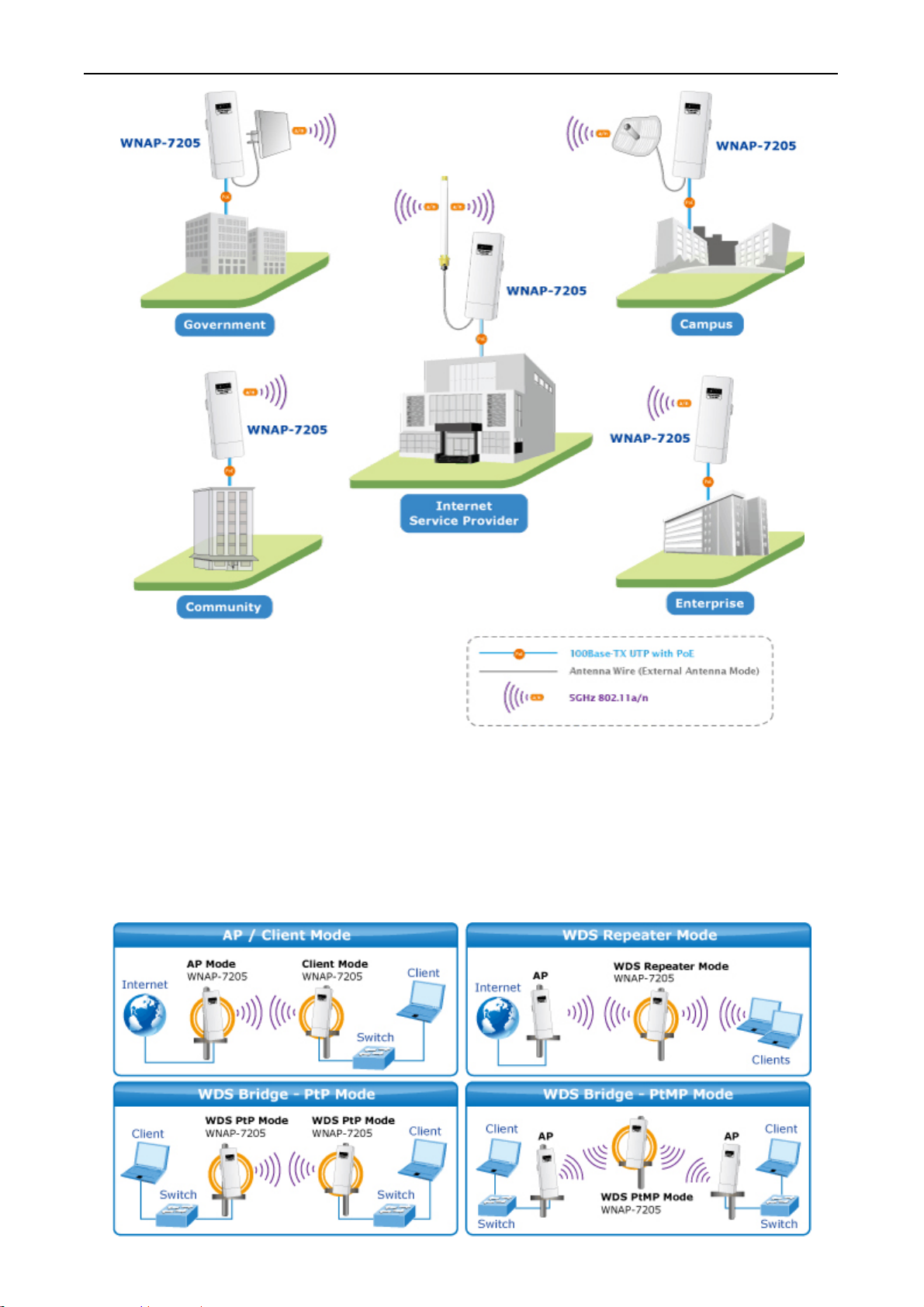
Multiple Operating & Wireless Modes
It supports multiple wireless communication connectivity (AP / Client CPE / WDS PtP / WDS PtMP /
Repeater / Universal Repeater), allowing for various application requirements that gives user more
comprehensive experience when using WNAP-7205. It also helps user easily to build wireless network
and extend the wireless range of existed wireless network.
- 8 -
Page 9

User’s Manual of WNAP-7205
Advanced Wireless Security
In aspect of security, besides 64/128- bit WEP encryption, the WNAP-7205 integrates WPA / WPA2,
WPA-PSK / WPA2-PSK and 802.1x authority to secure and protect your wireless LAN. The wireless
MAC filtering and SSID broadcast control to consolidate the wireless network security and prevent
unauthorized wireless connection.
Perfect Solution for Outdoor Environment
The WNAP-7205 is perfectly suitable to be installed in outdoor environments and exposed locations.
With its IP-55 casing protection, the WNAP-7205 can perform normally under rigorous weather
conditions including heavy rain and wind. With the proprietary Power over Ethernet (PoE) design, the
WNAP-7205 can be easily installed in the areas where power outlets are not available. It is the best
way using the WNAP-7205 to build outdoor wireless access applications between buildings on
campuses, business, rural areas and etc.
Easy Installation & Management
With User-friendly Web UI and step by step Setup Wizard, it is easier to install, even through a user
who never experiencing setup a wireless network.
- 9 -
Page 10

1.3 Product Features
Industrial Compliant Wireless LAN & LAN
Compliant with IEEE 802.11n wireless technology capable of up to 150Mbps data rate
Backward compatible with 802.11a standard
Equipped with 10/100Mbps RJ-45 Ports for LAN & WAN, Auto MDI/ MDI-X supported
Fixed-network Broadband Router
Supported connection types: Dynamic IP/ Static IP / PPPoE / PPTP / L2TP
Supports multiple sessions IPSec, L2TP and PPTP VPN pass-through
Supports Virtual Server, DMZ and Port Forwarding for various networking applications
Supports DHCP Server, UPnP, Dynamic DNS
RF Interface Characteristics
Built-in 16dBi Directional Antenna
User’s Manual of WNAP-7205
High Output Power Up to 300mW with multiple adjustable transmit power control
Reserve RP-SMA Type Connector
Outdoor Environmental Characteristics
IP55 Enclosure
Passive Power Over Ethernet Design
Reset Button on PoE Injector
Operating Temperature: -20~70 Degree C
Multiple Operation & Wireless Mode
Multiple Operation Modes: Bridge, Gateway, Ethernet Converter
Multiple Wireless Modes: AP, Client CPE(WISP), WDS PtP, WDS PtMP, Repeater,
Universal Repeater
Secure Network Connection
Supports Software Wi-Fi Protected Setup (WPS)
Advanced security: 64/128-bit WEP, WPA/WPA2, WPA-PSK/WPA2-PSK(TKIP/AES),
and 802.1x Authentication
Supports NAT firewall features, with SPI function to protect against DoS attacks
Supports IP / Protocol-Based access control and MAC Filtering
Easy Installation & Management
Web-Based UI and Quick Setup Wizard for easy configuration
Remote Management allows configuration from a remote site
System status monitoring includes DHCP Client, System Log
- 10 -
Page 11

1.4 Product Specification
User’s Manual of WNAP-7205
Product
Hardware
Standard support
Chipset
Memory
PoE
Interface
Antenna
WNAP-7205
150Mbps 802.11a/n Wireless Outdoor Access Point
IEEE802.11a/n
IEEE 802.3
IEEE 802.3u
IEEE 802.3x
Ralink RT2880
32 Mbytes DDR SDRAM
4 Mbytes Flash
Passive PoE
Reset Button on PoE Injector
Wireless: IEEE 802.11a/n, 1T1R
LAN: 1 x 10/100Base-TX, Auto-MDI/MDIX
WAN: 1 x 10/100Base-TX, Auto-MDI/MDIX
Internal (Default): 16dBi directional antenna (Vertical Polarization)
Horizontal: 60 degree
Vertical: 30 degree
External (Option): RP-SMA type Connector
Switchable by Software
For External Antenna Mode, attach antenna before power on.
802.11a: 54, 48, 36, 24, 18, 12, 9 and 6Mbps
Data Rate
Media Access Control
Modulation
Frequency Band 5.180GHz ~ 5.825GHz
Opt. Channel
802.11n (20MHz): up to 72Mbps
802.11n (40MHz): up to 150Mbp
CSMA/CA
Transmission/Emission Type: OFDM
Data modulation type: OFDM with BPSK, QPSK, 16-QAM, 64-QAM
5.180GHz-CH36
5.200GHz-CH40
5.220GHz-CH44
5.240GHz-CH48
5.260GHz-CH52
5.280GHz-CH56
5.300GHz-CH60
5.320GHz-CH64
5.500GHz-CH100
5.520GHz-CH104
5.540GHz-CH108
5.560GHz-CH112
5.580GHz-CH116
5.600GHz-CH120
- 11 -
Page 12
RF Output Power
Receiver Sensitivity
Output Power Control
User’s Manual of WNAP-7205
5.620GHz-CH124
5.640GHz-CH128
5.660GHz-CH132
5.680GHz-CH136
5.700GHz-CH140
5.745GHz-CH149
5.765GHz-CH153
5.785GHz-CH157
5.805GHz-CH161
5.825GHz-CH165
802.11a: 25 ± 1dBm
802.11n: 22 ± 1dBm
IEEE 802.11a: -90dBm
IEEE 802.11n: -88dBm
Range 1~100, default:100
Power Requirements
Environment & Certification
Operation Temp.
Storage Temp.
IP Level
Regulatory
Software
LAN
WAN
VPN Passthrough
12V DC, 1A (switching)
Temp.: -20~70 Degree C, Humidity: 10~90% non-condensing
Temp.: -30~80 Degree C, Humidity: 5~90% non-condensing
IP55
CE / FCC / RoHS
Built-in DHCP server supporting static IP address distributing
Supports UPnP
Supports IGMP Proxy, DNS Proxy
Supports 802.1d STP (Spanning Tree)
Static IP
Dynamic IP
PPPoE
PPTP
L2TP
PPTP
L2TP
IPSec
Operating Mode
Firewall
Wireless Mode
Bridge
Gateway
Ethernet Converter (WISP)
NAT firewall with SPI (Stateful Packet Inspection)
Built-in NAT server supporting Port Forwarding (Virtual Server), and DMZ
Built-in firewall with Port/ IP address/ MAC/ URL filtering
AP
Client
WDS PTP
- 12 -
Page 13

Channel Width
User’s Manual of WNAP-7205
WDS PTMP
WDS Repeater (AP+WDS)
Universal Repeater (AP+Client)
20MHz / 40MHz
Wireless Isolation
Encryption Type
Wireless Security
Max. Wireless Client
Max. WDS AP
Max. Wired Client
NTP
Management
Diagnostic tool
Enable to isolate each connected wireless clients
64/128-bits WEP, WPA, WPA-PSK, WPA2, WPA2-PSK, 802.1x
Provides wireless LAN ACL (Access Control List) filtering
Wireless MAC address filtering
Supports WPS (WIFI Protected Setup )
Enable/Disable SSID Broadcast
25
4
60
Network Time Management
Web UI, DHCP Client, Configuration Backup & Restore, Dynamic DNS
System Log
- 13 -
Page 14

User’s Manual of WNAP-7205
1.5 Wireless Performance
The following information will help you utilizing the wireless performance, and operating coverage of
WNAP-7205.
1. Site selection
To avoid interferences, please locate WNAP-7205 and wireless clients away from transformers,
microwave ovens, heavy-duty motors, refrigerators, fluorescent lights, and other industrial equipments.
Keep the number of walls, or ceilings between AP and clients as few as possible; otherwise the signal
strength may be seriously reduced. Place WNAP-7205 in open space or add additional WNAP-7205 as
needed to improve the coverage.
2. Environmental factors
The wireless network is easily affected by many environmental factors. Every environment is unique
with different obstacles, construction materials, weather, etc. It is hard to determine the exact operating
range of WNAP-7205 in a specific location without testing.
- 14 -
Page 15
Chapter 2. Hardware Description
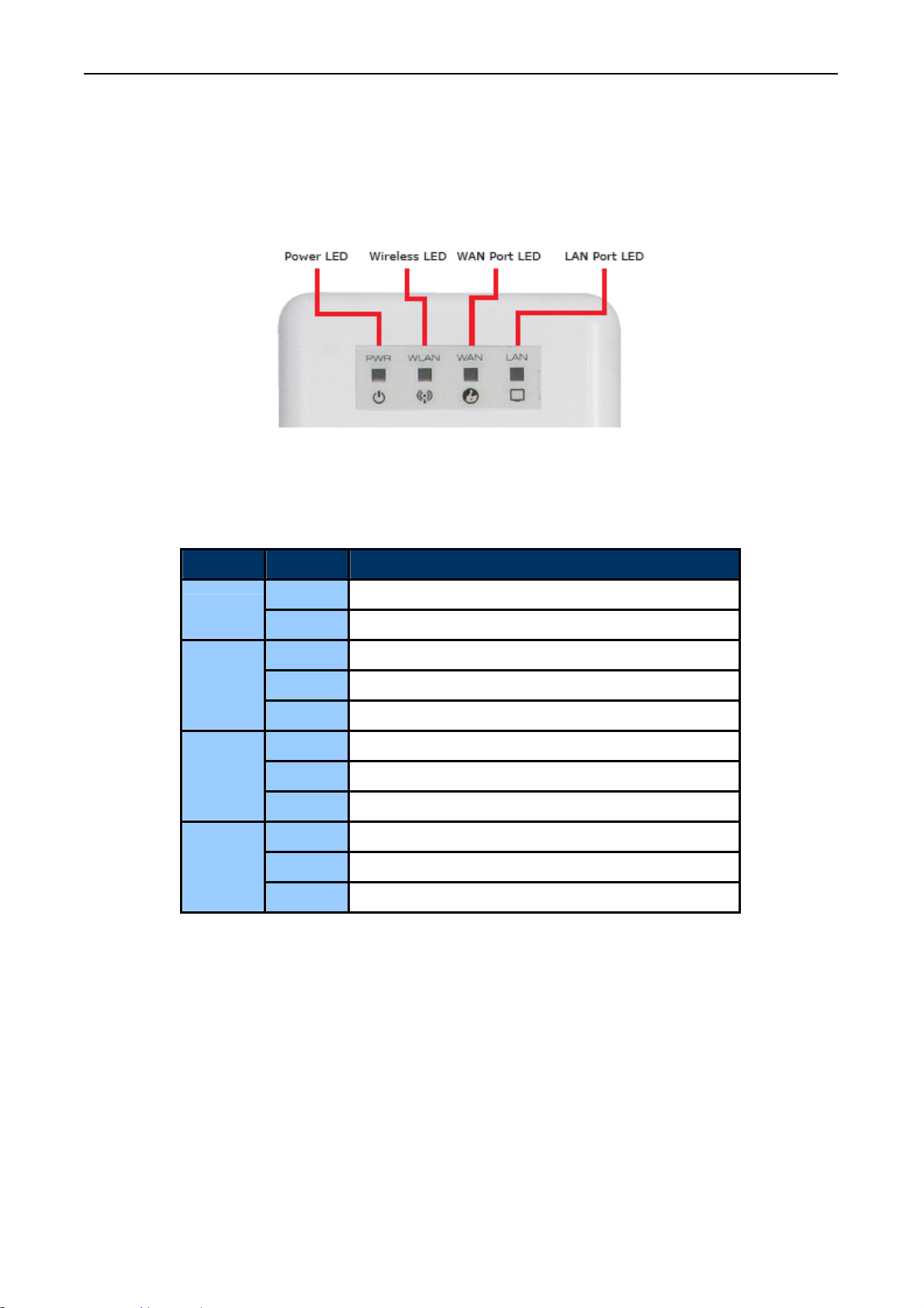
2.1 The Rear Panel – LED
Figure 2-1 Rear Panel LED Indication
User’s Manual of WNAP-7205
2.2 LED Indications
LED State Meaning
Power
WLAN
WAN
LAN
On System On
Off System Off
On Wireless Radio ON.
Off Wireless Radio Off.
Blinking Data is transmitting or receiving on the wireless.
On Port linked.
Off No link.
Blinking Data is transmitting or receiving on the WAN interface.
On Port linked.
Off No link.
Blinking Data is transmitting or receiving on the LAN interface.
- 15 -
Page 16
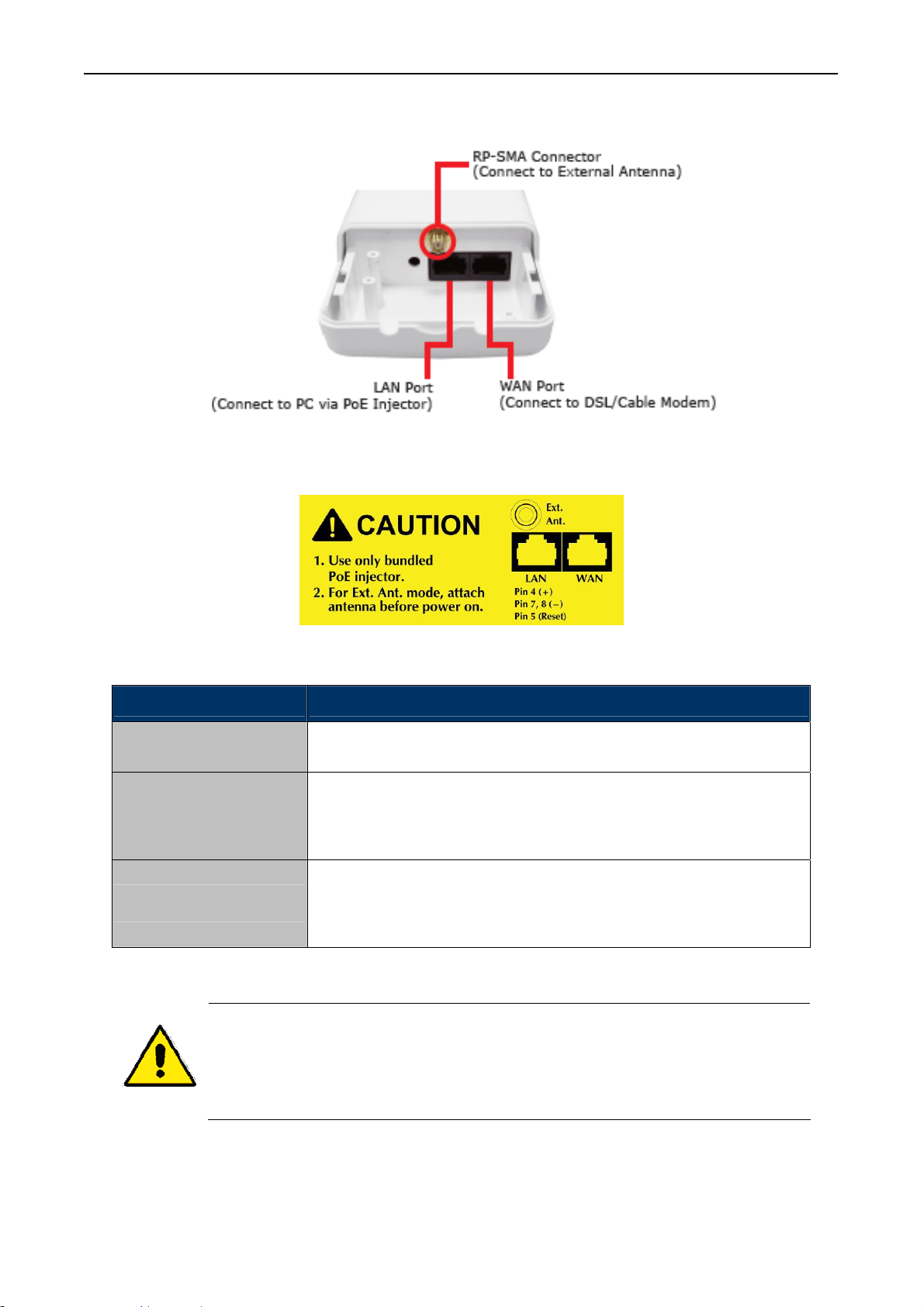
2.3 The Rear Panel – Port & Connector
Figure 2-2 Port and Connector of WNAP-7205
User’s Manual of WNAP-7205
Interface Function
RP-SMA Connector
LAN
WAN
1. For External Antenna Mode, you MUST physically attach antenna before power
Figure 2-3 Port and Connector description label
For external antenna. You can use the RP-SMA connector to connect
with 5GHz external antenna.
The RJ-45 sockets allow LAN connection through Category 5 cables.
Support auto-sensing on 10/100M speed and half/ full duplex; comply
with IEEE 802.3/ 802.3u respectively.
The RJ-45 socket allows WAN connection through a Category 5 cable.
Support auto-sensing on 10/100M speed and half/ full duplex; comply
with IEEE 802.3/ 802.3u respectively.
on.
2. For using external antenna, you should configure the Antenna Switch from
“Internal” to “External” via Web UI.
- 16 -
Page 17
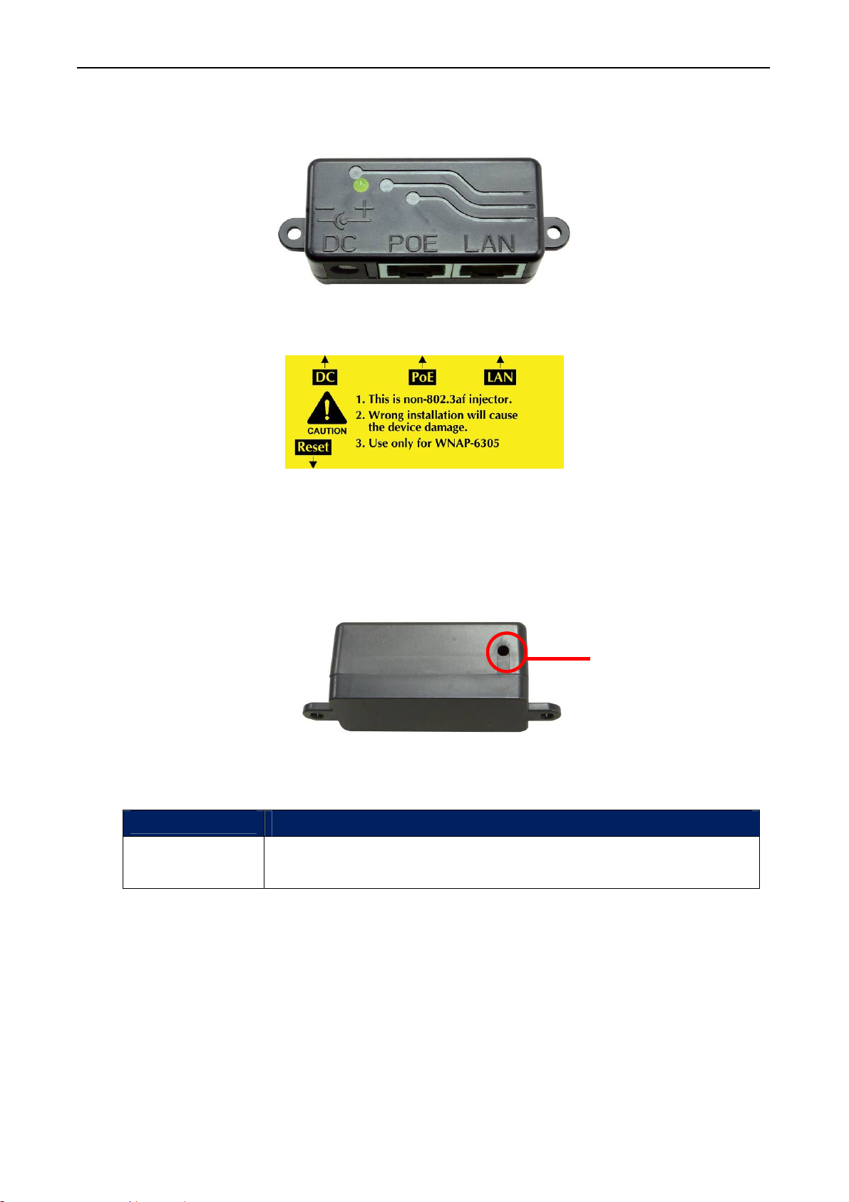
2.4 PoE Injector
User’s Manual of WNAP-7205
Figure 2-4 Top view of PoE Injector
Hardware Button
Active
Reset
Figure 2-5 Label of PoE Injector
Figure 2.6 Reset Button of PoE Injec
Time
Push continually the reset button of POE injector about 5 ~ 10 seconds to
reset the configuration parameters to factory defaults.
tor
Reset Button
- 17 -
Page 18

User’s Manual of WNAP-7205
Chapter 3. Hardware installation
This chapter describes safety precautions and product information you have to know and check before
installing WNAP-7205.
3.1 Preparation before Installation
3.1.1 Professional Installation Required
Please seek assistance from a professional installer who is well trained in the RF installation and
knowledgeable in the local regulations.
3.1.2 Safety Precautions
1. To keep you safe and install the hardware properly, please read and follow these safety
precautions.
2. If you are installing WNAP-7205 for the first time, for your safety as well as others’, please seek
assistance from a professional installer who has received safety training on the hazards
involved.
3. Keep safety as well as performance in mind when selecting your installation site, especially
where there are electric power and phone lines.
4. When installing WNAP-7205, please note the following things:
Do not use a metal ladder;
Do not work on a wet or windy day;
Wear shoes with rubber soles and heels, rubber gloves, long sleeved shirt or jacket.
5. When the system is operational, avoid standing directly in front of it. Strong RF fields are present
when the transmitter is on.
3.1.3 Installation Precautions
To keep the WNAP-7205 well while you are installing it, please read and follow these installation
precautions.
1. Users MUST use a proper and well-installed surge arrestor with the WNAP-7205; otherwise, a
random lightening could easily cause fatal damage to WNAP-7205. EMD (Lightning)
DAMAGE IS NOT COVERED UNDER WARRNTY.
2. Users MUST use the “Power cord & PoE Injector” shipped in the box with the WNAP-7205.
Use of other options will cause damage to the WNAP-7205.
3. Users MUST power off the WNAP-7205 first before connecting the external antenna to it.
Do not switch from built-in antenna to the external antenna from WEB management without
physically attaching the external antenna onto the WNAP-7205; otherwise, damage might be
caused to the WNAP-7205 itself.
- 18 -
Page 19
User’s Manual of WNAP-7205
3.2 Hardware Installation
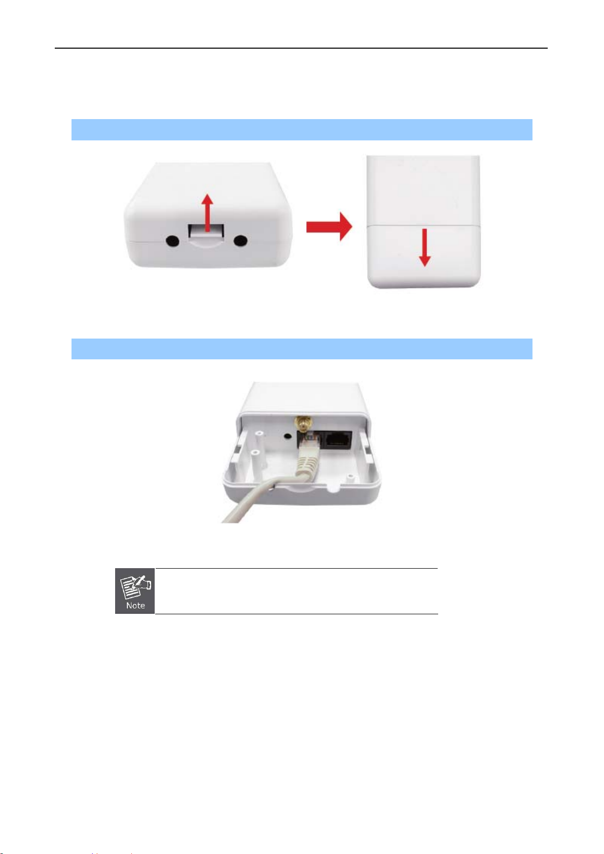
3.2.1 Connect Up
Step 1. Push the latch in the bottom of WNAP-7205 to remove the sliding cover.
Figure 3-1 Move the cover
Step 2. Plug the RJ-45 Ethernet cable into the LAN Port of WNAP-7205.
Figure 3-2 Cable Connection
RJ-45 8P8C Ethernet cable is required.
- 19 -
Page 20
User’s Manual of WNAP-7205
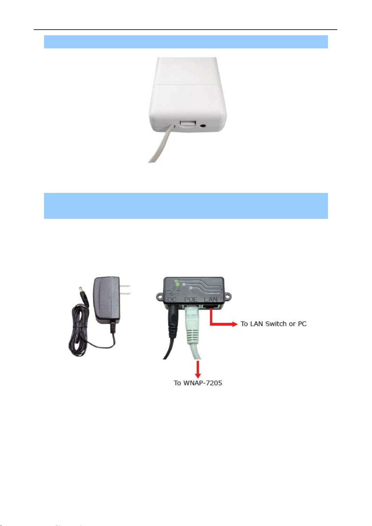
Step 3. Slide the cover back to seal the bottom of the WNAP-7205.
Figure 3-3 Seal the bottom
Step 4. Take out the power cord and PoE injector, plug the power cord into the DC port and plug the
other side of the RJ-45 cable in the STEP 2 into the POE port of the PoE injector.
DC: Insert adapter
POE: This hole is linked to LAN port of the Outdoor Router with RJ-45.
LAN: This hole is linked to LAN side PC/Hub or Router/ADSL modem device with RJ-45
Figure 3-4 Connect to PoE Injector
- 20 -
Page 21
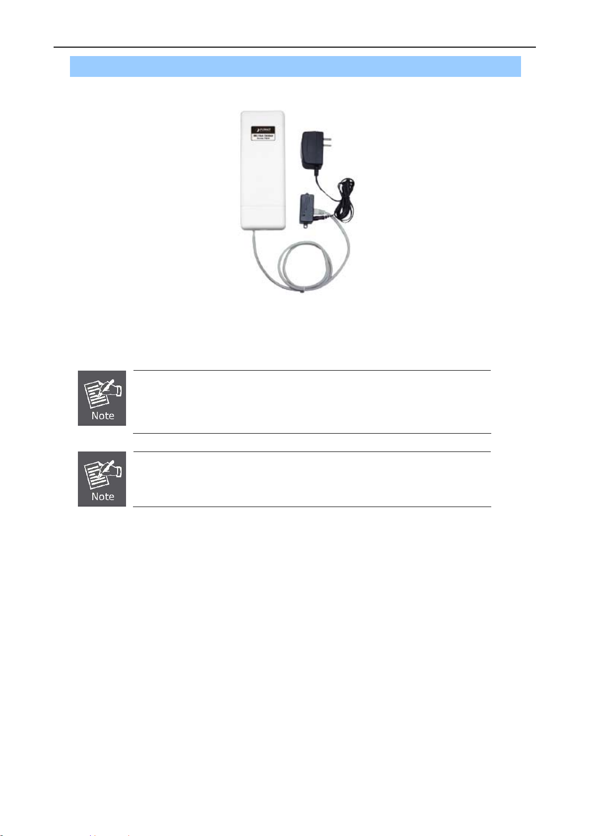
Step 5. Complete the hardware installation as diagram at below.
User’s Manual of WNAP-7205
Figure 3-5 Complete set
It will take about 50 seconds to complete the boot up sequence after powered on
the Outdoor Router; Power LED will be active, and after that the WLAN Activity
LED will be flashing to show the WLAN interface is enabled and working now.
To avoid thunder strike, consider to install ELA-100, thunder arrester toward the
CPE AP and the PoE injector.
- 21 -
Page 22
User’s Manual of WNAP-7205
3.2.2 Pole Mounting
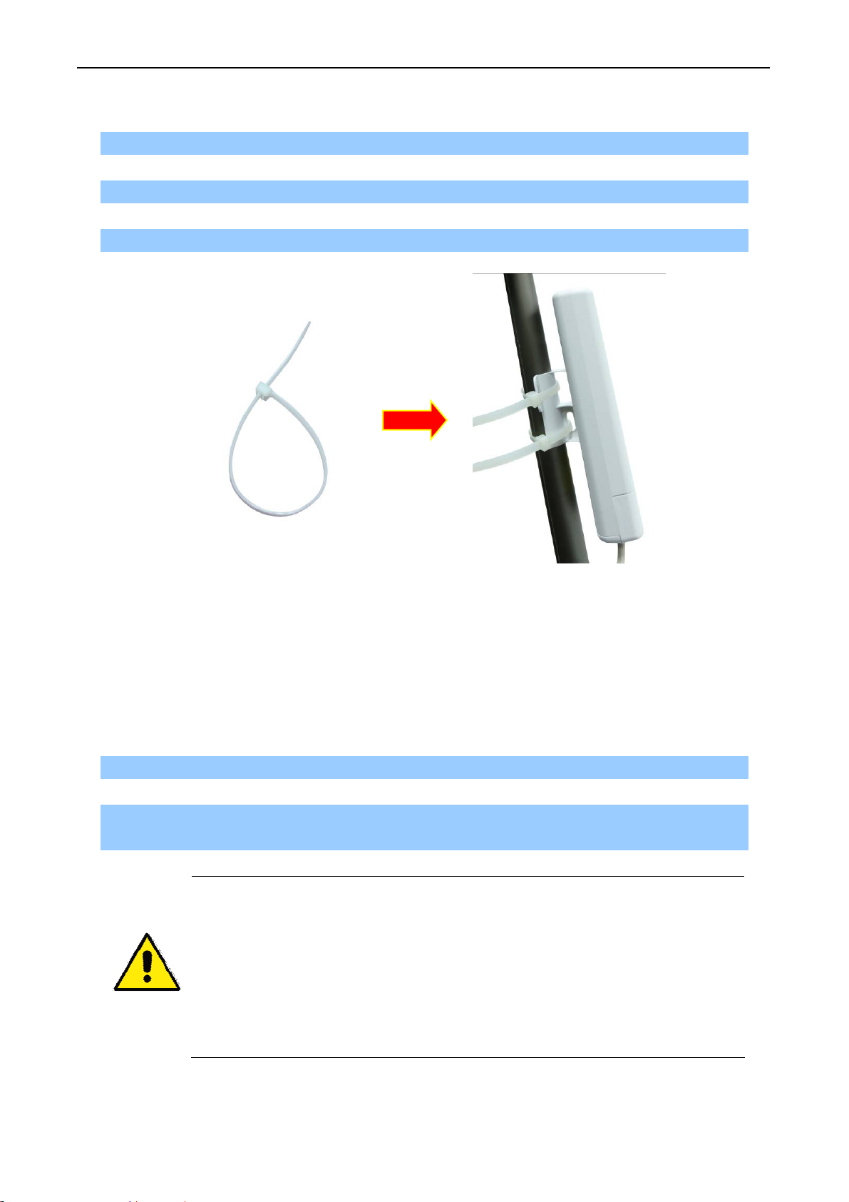
Step 1. Turn the WNAP-7205 over. Put the pole mounting tie through the middle hole of it.
Step 2. Mount WNAP-7205 steadily to the pole by fastening the mounting tie tightly.
Step 3. Now you have completed the hardware installation of WNAP-7205 as figure below.
Mounting Tie
Figure 3-6 Pole Mountin
g
3.2.3 Using the External Antenna
If you prefer to use the external antenna with RP-SMA Type connector for your application instead of
the built-in directional antenna, please follow the steps below.
Step 1. Connect your antenna with the RP-SMA Type connector on the bottom of WNAP-7205.
Step 2. Power on the WNAP-7205, and then go to Wireless Settings-> Basic to configure the
Antenna Switch from “Internal” to “External”.
1. If you are going to use an external antenna on WNAP-7205, get some cable in
advance.
1. Users MUST power off the WNAP-7205 first before connecting the external
antenna to it. Do not switch from built-in antenna to the external antenna from
WEB management without physically attaching the external antenna onto the
WNAP-7205; otherwise, damage might be caused to the WNAP-7205 itself.
- 22 -
Page 23
User’s Manual of WNAP-7205
Chapter 4. Software Installation
4.1 Software Configuration
There are web based management and configuration functions allowing you to have the jobs done
easily. The WNAP-7205 is delivered with the following factory default parameters on the Ethernet LAN
interfaces.
Default IP Address: 192.168.1.1
Default IP subnet mask: 255.255.255.0
WEB login User Name: admin
WEB login Password: admin
4.2 Connecting the AP
For OS of Microsoft Windows 2000/ XP:
1. Click the Start button and select Settings, then click Control Panel. The Control Panel window
will appear.
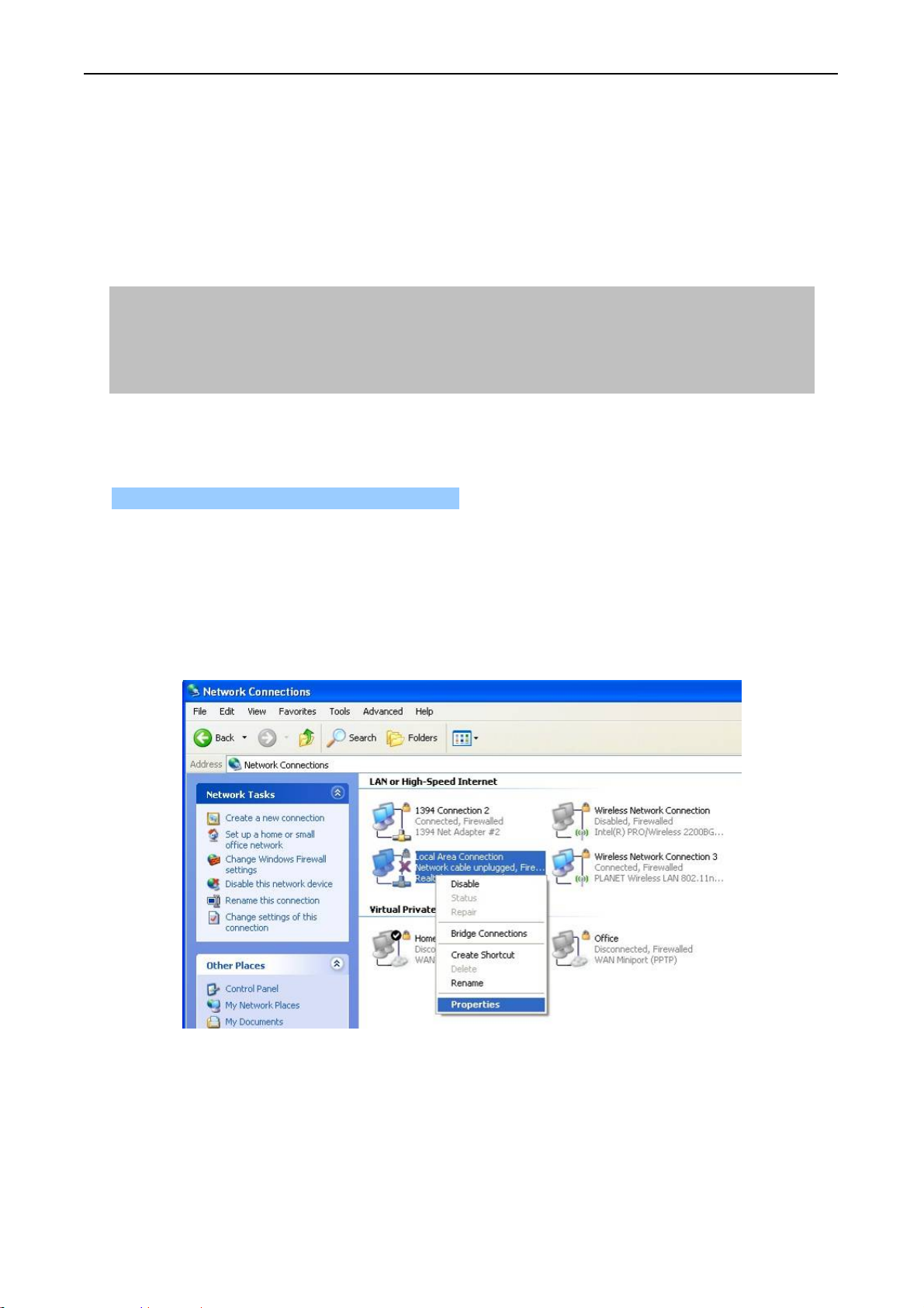
2. Move mouse and double-click the right button on Network and Dial-up Connections icon.
Move mouse and double-click the Local Area Connection icon. The Local Area Connection
window will appear. Click Properties button in the Local Area Connection window.
Figure 4-1
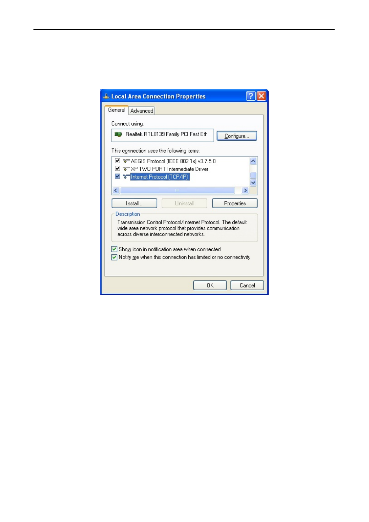
3. Check the installed list of Network Components. If TCP/IP is not installed, click the Add
button to install it; otherwise go to step 6.
4. Select Protocol in the Network Component Type dialog box and click Add button.
- 23 -
Page 24
User’s Manual of WNAP-7205
5. Select TCP/IP in Microsoft of Select Network Protocol dialog box then click OK button to
install the TCP/IP protocol, it may need the Microsoft Windows CD to complete the installation.
Close and go back to Network dialog box after the TCP/IP installation.
6. Select TCP/IP and click the properties button on the Network dialog box.
Figure 4-2
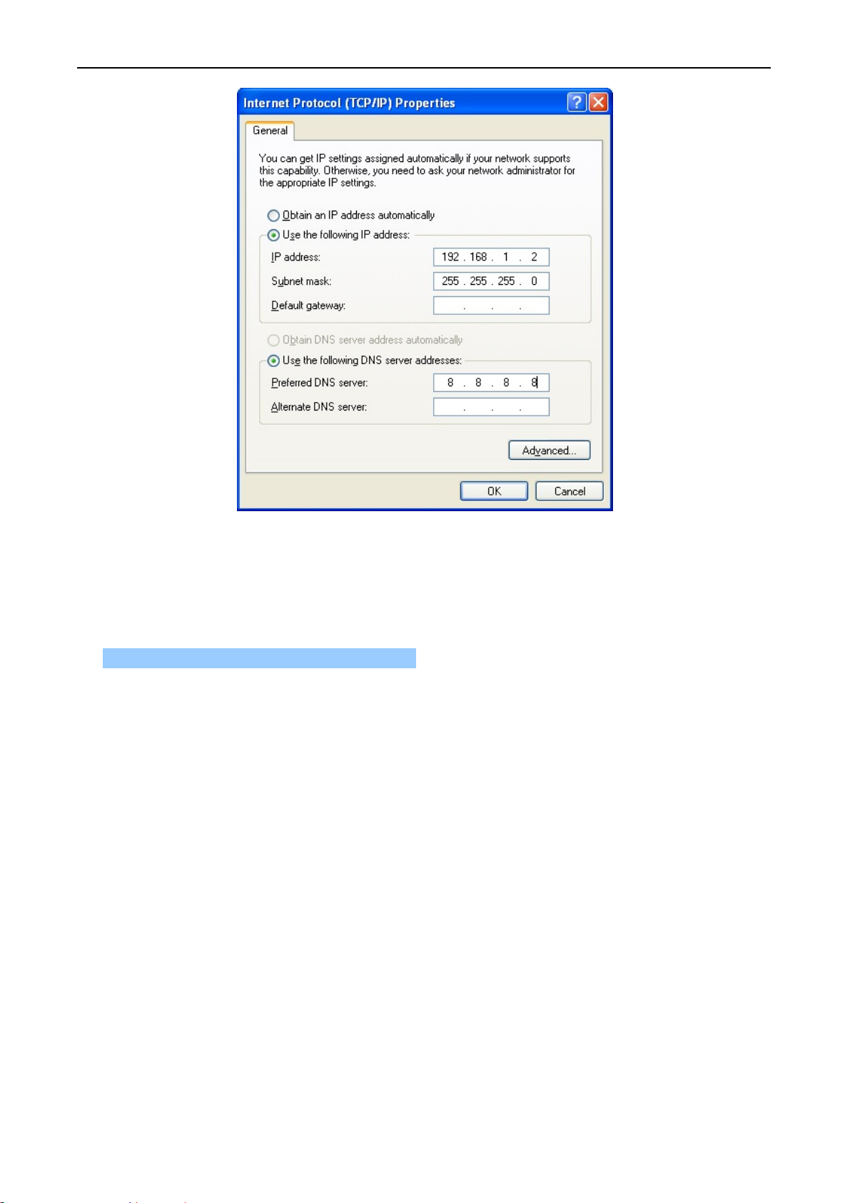
7. Select Specify an IP address and type in values as following example.
IP Address: 192.168.1.2, any IP address within 192.168.1.2 to 192.168.1.254 is good to
connect the Wireless LAN Access Point.
IP Subnet Mask: 255.255.255.0
- 24 -
Page 25
User’s Manual of WNAP-7205
Figure 4-3
8. Click OK to complete the IP parameters setting.
For OS of Microsoft Windows Vista / 7:
1. Click the Start button and select Settings, then click Control Panel. The Control Panel window
will appear.
2. Move mouse and double-click the right button on Network Connect ions item. The Network
Connections window will appear. Double click Local Area Connection icon, then User
Account Control window shown. Right click Continue button to set properties.
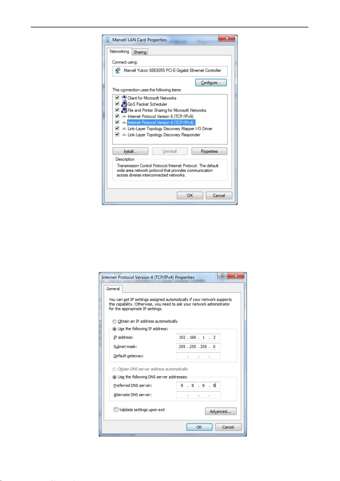
3. In Local Area Connection Properties window, Choose Networking tab, move mouse and
click Internet Protocol Version 4 (T CP/IPv4), then click Properties button.
- 25 -
Page 26
User’s Manual of WNAP-7205
Figure 4-4
4. Move mouse and click General tab, Select Specify an IP address and type in values as
following example.
IP Address: 192.168.1.2, any IP address within 192.168.1.2 to 192.168.1.254 is good to
connect the Wireless LAN Access Point. IP Subnet Mask: 255.255.255.0
Figure 4-5
- 26 -
Page 27

User’s Manual of WNAP-7205
5. Click OK to complete the IP parameters setting.
For OS of Microsoft Windows NT:
1. Click the Start button and select Settings, then click Control Panel. The Control Panel window will
appear.
2. Move mouse and double-click the right button on Network icon. The Network window will appear.
Click Protocol tab from the Network window.
3. Check the installed list of Network Protocol window. If TCP/IP is not installed, click the Add button
to install it; otherwise go to step 6.
4. Select Protocol in the Network Component Type dialog box and click Add button.
5. Select TCP/IP in Microsoft of Select Network Protocol dialog box then click OK button to install
the TCP/IP protocol, it may need the Microsoft Windows CD to complete the installation. Close
and go back to Network dialog box after the TCP/IP installation.
6. Select TCP/IP and click the properties button on the Network dialog box.
7. Select Specify an IP address and type in values as following example.
IP Address: 192.168.1.2, any IP address within 192.168.1.2 to 192.168.1.254 is good to connect
the Wireless LAN Access Point.
IP Subnet Mask: 255.255.255.0
8. Click OK to complete the IP parameters setting.
4.3 Web Login
Open a WEB browser, i.e. Microsoft Internet Explore 6.1 SP1 or above, then enter 192.168.1.1 on the
URL to connect the WNAP-7205.
Figure 4-6
After a moment, a login window will appear. Enter the User Name and Password. Then click the OK
button.
- 27 -
Page 28
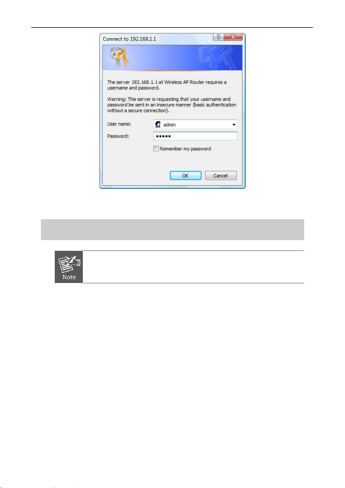
Figure 4-7 Login Window
User’s Manual of WNAP-7205
Default User name: admin
Default Password: admin
If the above screen does not pop up, it may mean that your web-browser has been set
to a proxy. Go to Tools menu>Internet Options>Connections>LAN Settings, in the
screen that appears, cancel the Using Proxy checkbox, and click OK to finish it.
After you enter the username and password, the main screen appears as Figure 4-8
- 28 -
Page 29

Figure 4-8 Web UI Screenshot
User’s Manual of WNAP-7205
The next chapter will introduce the functions of the web UI.
- 29 -
Page 30
User’s Manual of WNAP-7205
Chapter 5. Basic System Settings
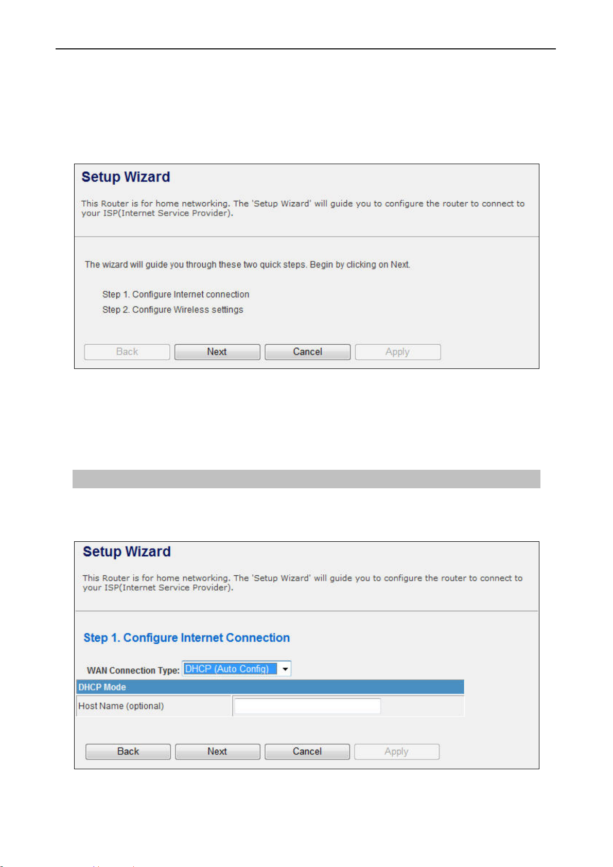
5.1 Setup Wizard
This Setup Wizard page guides you to configure the Internet connect and Wireless Setting quickly.
Figure 5-1 Setup Wizard
Click Next button to next step for Internet connection settings. There are five options (DHCP, Static
Mode, PPPOE, L2TP, PPTP) for Internet connection on WAN port.
a. DHCP (Auto Config)
If your ISP provides the DHCP service, please choose Dynamic IP type, and the Router will
automatically obtain IP parameters from your ISP. You can see the page as follows
Figure 5-2 Step 1. DHCP
- 30 -
Page 31

The page includes the following fields:
Object Description
User’s Manual of WNAP-7205
Host Name
This option specifies the Host Name of the Router.
b. Static IP Address
If your ISP provides a static or fixed IP Address, Subnet Mask, Gateway and DNS setting, select
Static Mode (fixed IP). The Static IP settings page will appear, shown as following.
Figure 5-3 Step 1. Static Mode
The page includes the following fields:
Object Description
IP Address
Subnet Mask
Enter the IP address in dotted-decimal notation provided by your ISP.
Enter the subnet Mask in dotted-decimal notation provided by your ISP,
usually is 255.255.255.0
Default Gateway
(Optional) Enter the gateway IP address in dotted-decimal notation
provided by your ISP.
Primary/Secondary DNS
(Optional) Enter one or two DNS addresses in dotted-decimal notation
provided by your ISP.
- 31 -
Page 32

User’s Manual of WNAP-7205
c. PPPOE Connection
If your ISP provides a PPPoE connection, select PPPoE option. And enter the following parameters.
The page includes the following fields:
Object Description
User Name/Password
Enter the User Name and Password provided by your ISP. These fields
are case-sensitive.
Verify Password
Fill in the password again for verification.
Keep Alive: Keep the PPPoE connection all the time. Please also
configure the Redial Period field.
On Demand: Please configure the Idle Time field. When time is
Operation Mode
up, the PPPoE connection will disconnect. The connection will
re-connect when any outgoing packet arise.
Manual: Let user connect the PPPoE connection manually.
Sometimes the connection cannot be terminated although you specify a time to
Idle Time, since some applications are visiting the Internet continually in the
Figure 5-4 Step 1. PPPOE
background.
- 32 -
Page 33

User’s Manual of WNAP-7205
d. L2TP
If your ISP provides L2TP connection, please select L2TP option. And enter the following parameters.
The page includes the following fields:
Object Description
L2TP Server IP Address
Allow user to make a tunnel with remote site directly to secure the data
transmission among the connection. User can use embedded L2TP
client supported by this router to make a VPN connection.
If you select the L2TP support on WAN interface, fill in the IP address
for it.
User Name/Password
Enter the User Name and Password provided by your ISP. These fields
are case-sensitive.
Address Mode
Static: To configure the IP address information by manually,
please fill in the related setting at below.
Dynamic: The option allows the machine to get IP address
information automatically from DHCP server on WAN side.
Figure 5-5 Step 1. L2TP
- 33 -
Page 34

User’s Manual of WNAP-7205
IP Address
Subnet Mask
Default Gateway
Operation Mode
Fill in the IP address for WAN interface.
Fill in the subnet mask for WAN interface.
Fill in the default gateway for WAN interface out going data packets.
Keep Alive: Keep the L2TP connection all the time. Please also
configure the Redial Period field.
Manual: Let user connect the L2TP connection manually.
e. PPTP
If your ISP provides PPTP connection, please select PPTP option. And enter the following parameters.
Figure 5-6 Step1. PPTP
- 34 -
Page 35

The page includes the following fields:
Object Description
User’s Manual of WNAP-7205
PPTP Server IP
Address
User Name/Password
Address Mode
IP Address
Subnet Mask
Allow user to make a tunnel with remote site directly to secure the data
transmission among the connection. User can use embedded PPTP
client supported by this router to make a VPN connection.
If you select the PPTP support on WAN interface, fill in the IP address
for it.
Enter the User Name and Password provided by your ISP. These fields
are case-sensitive.
Static: To configure the IP address information by manually, please fill
in the related setting at below.
Dynamic: The option allows the machine to get IP address
information automatically from DHCP server on WAN side.
Fill in the IP address for WAN interface.
Fill in the subnet mask for WAN interface.
Default Gateway
Operation Mode
Fill in the default gateway for WAN interface out going data packets.
Keep Alive: Keep the PPTP connection all the time. Please also
configure the Redial Period field.
Manual: Let user connect the PPTP connection manually.
When you finish these settings, then click Next button to jump at Step2.
Step 2: configure Wireless Settings
There are five options (Disable, OPENWEP, SHAREDWEP, WPA-PSK, WPA2-PSK) for Wireless
security connection.
- 35 -
Page 36

User’s Manual of WNAP-7205
Object Description
Network Mode
Frequency (Channel)
Network Name (SSID)
Figure 5-7 Step2. Configure Wireless Settings
This field determines the wireless mode which the Router works on.
This field determines which operating frequency will be used. The
default channel is set to AutoSelect, so the router will choose the best
channel automatically. It is not necessary to change the wireless
channel unless you notice interference problems with another nearby
access point.
Enter a value of up to 32 characters. The same name of SSID (Service
Set Identification) must be assigned to all wireless devices in your
network. Considering your wireless network security, the default SSID
is set to be default. This value is case-sensitive. For example, PLANET
is NOT the same as planet.
Channel Bandwidth Select the operating channel width 20 MHz or 20/40 MHz.
Disable: No security required
Security Mode
OPENWEP / SHAREDWEP:
When you select WEP, please input 5, 13 (ASCII), 10 or 26
(HEX) characters for WEP Key.
WPA-PSK / WPA2-PSK: You can enter ASCII characters between
8 and 63 characters or 8 to 64 Hexadecimal characters.
When you finish these settings, then click Apply button to save.
- 36 -
Page 37

5.2 Operation Mode
User’s Manual of WNAP-7205
Figure 5-8 Operation Mode Configurations
a. Bridge:
The Bridge mode allows that all Ethernet and wireless interfaces are bridged into a single Bridge
interface.
Figure 5-9 WDS Bridge
b. Gateway:
The Gateway mode allows that the first Ethernet port is treated as WAN port and the Ethernet port
and the wireless interface are bridged together and are treated as LAN ports.
c. Wireless ISP:
The Wireless ISP mode allows that the wireless interface is treated as WAN port, and the Ethernet
ports are LAN ports.
- 37 -
Page 38

5.3 Internet Settings
5.3.1 WAN
User’s Manual of WNAP-7205
a. STATIC
Object Description
IP Address
Subnet Mask
Default Gateway
Primary/Secondary DNS
b. DHCP
Object Description
Host Name
Figure 5-10 WAN Settings
Enter the IP address in dotted-decimal notation provided by your ISP.
Enter the subnet Mask in dotted-decimal notation provided by your ISP,
usually is 255.255.255.0
(Optional) Enter the gateway IP address in dotted-decimal notation
provided by your ISP.
(Optional) Enter one or two DNS addresses in dotted-decimal notation
provided by your ISP.
This option specifies the Host Name of the Router.
MAC Clone
Take NIC MAC address of PC on LAN side as the MAC address of
WAN interface.
- 38 -
Page 39

c. PPPoE
User’s Manual of WNAP-7205
Object Description
User Name/Password
Verify Password
Operation Mode
d. L2TP
Object Description
L2TP Server IP Address
Enter the User Name and Password provided by your ISP. These fields
are case-sensitive.
Fill in the password again for verification.
Keep Alive: Keep the PPPoE connection all the time. Please also
configure the Redial Period field.
On Demand: Please configure the Idle Time field. When time is up, the
PPPoE connection will disconnect. The connection will re-connect
when any outgoing packet arise.
Manual: Let user connect the PPPoE connection manually.
Allow user to make a tunnel with remote site directly to secure the data
transmission among the connection. User can use embedded L2TP
client supported by this router to make a VPN connection.
User Name/Password
Address Mode
IP Address
Subnet Mask
Default Gateway
Operation Mode
If you select the L2TP support on WAN interface, fill in the IP address
for it.
Enter the User Name and Password provided by your ISP. These fields
are case-sensitive.
Static: To configure the IP address information by manually,
please fill in the related setting at below.
Dynamic: The option allows the machine to get IP address
information automatically from DHCP server on WAN side.
Fill in the IP address for WAN interface.
Fill in the subnet mask for WAN interface.
Fill in the default gateway for WAN interface out going data packets.
Keep Alive: Keep the L2TP connection all the time. Please also
configure the Redial Period field.
Manual: Let user connect the L2TP connection manually.
e. PPTP
Object Description
PPTP Server IP
Allow user to make a tunnel with remote site directly to secure the data
transmission among the connection. User can use embedded PPTP
- 39 -
Page 40

User’s Manual of WNAP-7205
Address
User Name/Password
Address Mode
IP Address
Subnet Mask
Default Gateway
Operation Mode
client supported by this router to make a VPN connection.
If you select the PPTP support on WAN interface, fill in the IP address
for it.
Enter the User Name and Password provided by your ISP. These fields
are case-sensitive.
Static: To configure the IP address information by manually,
please fill in the related setting at below.
Dynamic: The option allows the machine to get IP address
information automatically from DHCP server on WAN side.
Fill in the IP address for WAN interface.
Fill in the subnet mask for WAN interface.
Fill in the default gateway for WAN interface out going data packets.
Keep Alive: Keep the PPTP connection all the time. Please also
configure the Redial Period field.
Manual: Let user connect the PPTP connection manually.
- 40 -
Page 41

5.3.2 LAN
User’s Manual of WNAP-7205
Figure 5-11 LAN Settings
The page includes the following fields:
Object Description
MAC Address
IP Address
Subnet Mask
Default Gateway Fill in the default gateway for LAN interfaces out going data packets.
DHCP Type
The physical address of the Router, as seen from the LAN. The value
can't be changed.
Enter the IP address of your Router or reset it in dotted-decimal
notation (factory default: 192.168.1.1).
An address code that determines the size of the network. Normally use
255.255.255.0 as the subnet mask.
Disable: Disable DHCP server on LAN side.
- 41 -
Page 42

Start IP Address
User’s Manual of WNAP-7205
Server: Enable DHCP server on LAN side.
Fill in the start IP address to allocate a range of IP addresses; client
with DHCP function set will be assigned an IP address from the range.
End IP Address
Lease Time Fill in the lease time of DHCP server function.
802.1d Spanning Tree
LLTD
IGMP Proxy
UPNP Select enable or disable the UPnP protocol from pull-down menu.
DNS Proxy Select enable or disable the DNS Proxy function from pull-down menu.
Fill in the end IP address to allocate a range of IP addresses; client
with DHCP function set will be assigned an IP address from the range.
Select enable or disable the IEEE 802.1d Spanning Tree function from
pull-down menu.
Select enable or disable the Link Layer Topology Discover function
from pull-down menu.
Select enable or disable the IGMP proxy function from pull-down
menu.
- 42 -
Page 43

User’s Manual of WNAP-7205
5.3.3 DHCP Clients
The “DHCP clients” page shows all the active DHCP clients. The table window shows the active clients
with their Hostname, MAC address, assigned IP address, and time expired information.
Figure 5-12 DHCP Clients
5.3.4 VPN Passthrough
Figure 5-13 VPN Passthrough
The page includes the following fields:
Object Description
L2TP Passthrough Select enable or disable the L2TP pass-through function from
pull-down menu.
IPSec Passthrough Select enable or disable the IPSec pass-through function from
pull-down menu.
PPTP Passthrough Select enable or disable the PPTP pass-through function from
pull-down menu.
- 43 -
Page 44

5.4 Wireless
5.4.1 Basic
User’s Manual of WNAP-7205
Figure 5-14 Basic Wireless Settings
The page includes the following fields:
Object Description
Wireless On/Off
Click Wireless OFF button to turn off wireless RF radio.
Click Wireless ON button to turn on wireless RF radio.
- 44 -
Page 45

User’s Manual of WNAP-7205
Antenna Switch
Wireless Mode
Wireless Band
Select Internal antenna or External antenna for using.
The default is using Internal antenna.
Click to select Wireless Mode from pull down menu.
There are 4 options available:
AP
AP Client (Universal Repeater Mode)
AP+WDS (WDS Repeater Mode)
WDS (WDS Bridge Mode)
Click to select Wireless Band from pull down menu.
There are 3 options available:
802.11a(5G)
802.11a/n mixed
802.11n(5G)
SSID
Multiple SSID 1~3
Broadcast Network
Name (SSID)
AP Isolation
MBSSID AP Isolation
It is the wireless network name. The SSID can be 32 bytes long.
User can use the default SSID or change it.
There are 3 multiple SSIDs available. Enter their descriptive names that
you want to use.
Enable or disable the SSID broadcast function.
Wireless network is similar to the virtual local area network. All of the
Wireless client devices can access each other completely.
When you enable this function, it will turn off connection between
wireless clients. Only allows connection between wireless client and
this AP router.
Enable this function will turn off connection between clients with
different MBSSID. Example: The client connected with BSSID 1. When
enable this function, it will not connect with BSSID 2. Only can access
between clients with SSID 1.
BSSID
Frequency (Channel)
Operating Mode
Show the MAC address of Wireless interface.
Select the wireless communication frequency/channel from pull-down
menu.
Select “Mixed Mode” for 11a/n mode or “Green Field” for 11n mode.
- 45 -
Page 46

User’s Manual of WNAP-7205
Channel BandWidth
Guard Interval
MCS
Select the operating channel width 20 MHz or 20/40 MHz.
Select “Long” or “Auto”. Guard intervals are used to ensure that distinct
transmissions do not interfere with one another. Only effect under
Mixed Mode.
Select 0~7 or “Auto” from pull down menu. The default is “Auto”. Only
effect under Mixed Mode.
- 46 -
Page 47

5.4.2 Advanced Wireless
User’s Manual of WNAP-7205
Figure 5-15 Advanced Wireless Settings
The page includes the following fields:
Object Description
Beacon Interval
Beacons are the packets sending by Access point to synchronize the
wireless network. The beacon interval is the time interval between
beacons sending by this unit in AP or AP+WDS operation. The default
and recommended beacon interval is 100 milliseconds.
- 47 -
Page 48

User’s Manual of WNAP-7205
Data Beacon Rate(DTM)
Fragment Threshold
RTS Threshold
This is the Delivery Traffic Indication Map. It is used to alert the clients
that multicast and broadcast packets buffered at the AP will be
transmitted immediately after the transmission of this beacon frame.
You can change the value from 1 to 255. The AP will check the buffered
data according to this value. For example, selecting “1” means to check
the buffered data at every beacon.
The fragmentation threshold determines the size at which packets are
fragmented (sent as several pieces instead of as one block). Use a low
setting in areas where communication is poor or where there is a great
deal of radio interference. This function will help you to improve the
network performance.
The RTS threshold determines the packet size at which the radio issues
a request to send (RTS) before sending the packet. A low RTS
Threshold setting can be useful in areas where many client devices are
associating with the device, or in areas where the clients are far apart
and can detect only the device and not each other. You can enter a
setting ranging from 0 to 2347 bytes.
TX Power
Short Preamble
Short Slot
TX Burst
Country Code
Carrier Detect
The default TX power is 100%. In case of shortening the distance and
the coverage of the wireless network, input a smaller value to reduce
the radio transmission power. For example, input 80 to apply 80% Tx
power.
Default: Disable. It is a performance parameter for 802.11 b/g mode
and not supported by some of very early stage of 802.11b station cards.
If there is no such kind of stations associated to this AP, you can enable
this function.
It is used to shorten the communication time between this AP and
station.
The device will try to send a serial of packages with single ACK reply
from the clients. Enable this function to apply it.
Select the country code for wireless from pull down menu.
Select Enabled to enable Carrier Detect.
- 48 -
Page 49

5.4.3 Wi-Fi Multimedia (WMM)
User’s Manual of WNAP-7205
Figure 5-16 WMM Settings
- 49 -
Page 50

The page includes the following fields:
Object Description
WMM Capable Enable or disable WMM.
APSD Capable Enable or disable APSD.
DLS Capable Enable or disable DLS.
User’s Manual of WNAP-7205
WMM Parameters
Click WMM Configuration button to pop up WMM Parameters of
Access Point page. You can configure WMM parameters in the page.
- 50 -
Page 51

5.4.4 Security
a. Disable
User’s Manual of WNAP-7205
Figure 5-17 Wireless Security Settings
If you set Security Mode to “Disable”, the wireless data transmission will not include encryption to
prevent from unauthorized access and monitoring.
b. OPEN-WEP
- 51 -
Page 52

User’s Manual of WNAP-7205
Figure 5-18 OPEN-WEP
If you set Security Mode to “OPEN-WEP” or “SHARED-WEP”, please fill in the related configurations
at below.
Object Description
Default Key Specify a Key number for effective.
WEP Keys
(1~4)
When you select the encryption type as WEP, please input 5, 13
(ASCII), 10 or 26 (HEX) characters for WEP Key.
- 52 -
Page 53

c. SHARED-WEP
User’s Manual of WNAP-7205
Figure 5-19 SHARED-WEP
If you set Security Mode to “OPEN-WEP” or “SHARED-WEP”, please fill in the related configurations
at below.
Object Description
Default Key Specify a Key number for effective.
WEP Keys
(1~4)
When you select the encryption type as WEP, please input 5, 13
(ASCII), 10 or 26 (HEX) characters for WEP Key.
- 53 -
Page 54

d. WPA-RADIUS
User’s Manual of WNAP-7205
Figure 5-20 WPA-RADIUS
The page includes the following fields:
Object Description
WPA Cipher Suite Select TKIP, AES or TKIPAES for WPA algorithms.
Key Renewal Interval Please fill in a number for Group Key Renewal interval time.
IP Address Enter the RADIUS Server’s IP Address provided by your ISP.
Enter the RADIUS Server’s port number provided by your ISP.
Port
(The Default is 1812.)
Enter the password that the Wireless Router shares with the RADIUS
Shared Secret
Server.
Session timeout interval is for 802.1x re-authentication setting. Set to
Session Timeout
zero to disable 802.1x re-authentication service for each session.
Session timeout interval unit is second and must be larger than 60.
Idle Timeout Enter the idle timeout in the column.
- 54 -
Page 55

e. WPA-PSK
User’s Manual of WNAP-7205
Figure 5-21 WPA-PSK
The page includes the following fields:
Object Description
WPA Cipher Suite
Select TKIP, AES or TKIPAES for WPA algorithms.
Pre-Shared Key Please fill in a passphrase like ‘test wpa 123’, or a hexadecimal string
like '65E4 E123 456 E1'.
Key Renewal Interval
Please fill in a number for Group Key Renewal interval time.
- 55 -
Page 56

f. WPA2-RADIUS
User’s Manual of WNAP-7205
Figure 5-22 WPA2-RADIUS
The page includes the following fields:
Object Description
WPA Cipher Suite Select TKIP, AES or TKIPAES for WPA algorithms.
Key Renewal Interval Please fill in a number for Group Key Renewal interval time.
Only valid in WPA2 security. Set WPA2 PMKID cache timeout period,
PMK Cache Period
after time out, the cached key will be deleted. PMK Cache Period unit
is minute.
Only valid in WPA2 security. The most important features beyond
WPA to become standardized through 802.11i/WPA2 are:
Pre-Authentication
Pre-authentication, which enables secure fast roaming without
noticeable signal latency.
- 56 -
Page 57

User’s Manual of WNAP-7205
Shared Secret
Enter the password that the Wireless Router shares with the RADIUS
Server.
Session timeout interval is for 802.1x re-authentication setting. Set to
Session Timeout
zero to disable 802.1x re-authentication service for each session.
Session timeout interval unit is second and must be larger than 60.
IP Address Enter the RADIUS Server’s IP Address provided by your ISP.
Port Enter the RADIUS Server’s port number provided by your ISP. (The
Default is 1812.)
Shared Secret Enter the password that the Wireless Router shares with the RADIUS
Server.
Session Timeout Session timeout interval is for 802.1x re-authentication setting. Set to
zero to disable 802.1x re-authentication service for each session.
Session timeout interval unit is second and must be larger than 60.
Idle Timeout Enter the idle timeout in the column.
g. WPA2-PSK
Figure 5-23 WPA2-PSK
- 57 -
Page 58

The page includes the following fields:
Object Description
User’s Manual of WNAP-7205
WPA Cipher Suite
Pre-Shared Key
Key Renewal Interval
h. 802.1X
Select TKIP, AES or TKIPAES for WPA algorithms.
Please fill in a passphrase like ‘test wpa 123’, or a hexadecimal string
like '65E4 E123 456 E1'.
Please fill in a number for Group Key Renewal interval time.
The page includes the following fields:
Object Description
WEP
IP Address
Port
Enable or Disable WEP encryption.
Enter the RADIUS Server’s IP Address provided by your ISP.
Enter the RADIUS Server’s port number provided by your ISP. (The
Default is 1812.)
Figure 5-24 802.1X
- 58 -
Page 59

User’s Manual of WNAP-7205
Shared Secret
Session Timeout
Idle Timeout
e. Access Policy
Enter the password that the Wireless Router shares with the RADIUS
Server.
Session timeout interval is for 802.1x re-authentication setting. Set to
zero to disable 802.1x re-authentication service for each session.
Session timeout interval unit is second and must be larger than 60.
Enter the idle timeout in the column.
The page includes the following fields:
Object Description
Policy
Add a station MAC
Select the Disabled, Allow or Reject of drop down menu choose
wireless access control mode. This is a security control function; only
those clients registered in the access control list can link to this WLAN
Broadband Router.
Fill in the MAC address of client to register this AP router access
capability.
Figure 5-25 Access Policy
- 59 -
Page 60

User’s Manual of WNAP-7205
5.4.5 WDS
In the Basic Wireless Settings page, select the Wireless Mode to “WDS” to setup the WDS connection.
a. WDS Mode
WDS mode allows user to operate as a standard WDS that forwards traffic between WDS links (links
that connect to other units in Repeater). The MAC addresses of WDS peers must be configured on the
Wireless 11n Access Points/ Repeaters. Basically this mode is used when you have a 2.4GHz outdoor
router with more than one WDS link to other AP/Repeaters.
Note: In this mode wireless clients will not be able to connect to the 2.4GHz outdoor router directly.
Step 1. In the Basic Wireless Settings, configure Wireless Mode to “WDS”.
Figure 5-26 Wireless Mode - WDS
- 60 -
Page 61
User’s Manual of WNAP-7205
A
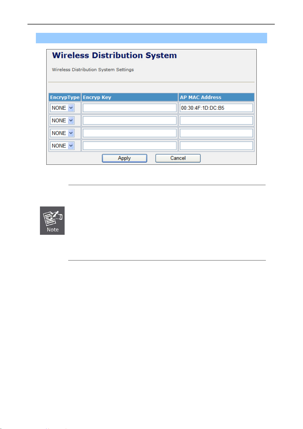
Step 2. Go to “Wireless Settings-> WDS”, fill in the MAC Address of the remote site.
Figure 5-27 WDS Configuration
1. To Setup the WDS Connection, the channel must be the same in both sites. You
should fix the channel from “AutoSelect” to a static one.
2. You must fill in the MAC Address by each other. For example, enter the MAC
Address of the remote site to the settings of local site; and enter the M
of the local site to the settings of remote site.
C Address
3. The Encryption Type must be the same in both sites if available.
c. AP+WDS (Repeater) Mode
Repeater mode allows user to operate as a wireless repeater, extending the range for remote wireless
clients and connecting them to an AP connected to the wired network. The MAC addresses of WDS
peers must be configured on the Wireless 2.4G Access Point/Repeater.
- 61 -
Page 62

User’s Manual of WNAP-7205
Step 1. In the Basic Wireless Settings, configure Wireless Mode to “AP+WDS”.
Figure 5-28 Wireless Mode – AP+WDS
- 62 -
Page 63

User’s Manual of WNAP-7205
A
Step 3. Go to “Wireless Settings-> WDS”, fill in the MAC Address of the remote site.
Figure 5-29 WDS Configuration
1. To Setup the WDS Connection, the channel must be the same in both sites. You
should fix the channel from “AutoSelect” to a static one.
2. You must fill in the MAC Address by each other. For example, enter the MAC
ddress of the remote site to the settings of local site; and enter the MAC Address
of the local site to the settings of remote site.
3. The Encryption Type must be the same in both sites if available.
- 63 -
Page 64

User’s Manual of WNAP-7205
5.4.6 Site Survey
This page is used to view or configure other APs near yours.
To connect with other AP by site survey, you need to configure the WNAP-7205 as “AP Client” mode in
the Basic Wireless Settings page as following.
Step 1. Go to “Wireless Settings-> Basic”, select the Wireless Moe to “AP Client”.
Figure 5-30 Basic Wireless Settings
Step 2. Go to “Wireless Settings->Site Survey” to scan the AP. Select the AP that you choose to
connect, and then click “Next”.
Figure 5-31 Site Survey - 1
- 64 -
Page 65

The page includes the following fields:
Object Description
User’s Manual of WNAP-7205
SSID
BSSID
RSSI
Channel
Encrypt
Wireless Mode
It shows the SSID of AP.
It shows BSSID of AP.
It shows the signal strength of current AP.
It show the current channel of AP occupied.
It shows the encryption status.
It show the wireless mode of AP.
Step 3. If the AP has encryption setting, it will pop out a window for you filling the encryption setting.
Please fill up the code, in this case, the code was “1234567890”, and click “Apply” to connect with
the AP.
Figure 5-32 Site Survey - 2
- 65 -
Page 66

User’s Manual of WNAP-7205
Step 4. After connected with AP, you can open “Status” page under Administrator to check link
status.
Figure 5-33 AP Status - Connected
If the Repeater Status is “Disconnected”, please check your security setting and
wireless channel, both AP & Client should be the same.
- 66 -
Page 67

User’s Manual of WNAP-7205
5.4.7 WPS
This section will guide you to add a new wireless device quickly to an existing network by WPS (Wi-Fi
Protected Setup) function.
Step 1. Choose menu “WPS”, you will see the next screen.
Figure 5-34 WPS Setup
The page includes the following fields:
Object Description
WPS Select Enable or Disable the Wi-Fi Protected Setup function. Then
click Apply button to take effect function after change.
WPS Summary After enabling the WPS function, if there is connection the WPS
Summary will show related information and status.
AP PIN Here shows the AP’s PIN code (Personal Identification Number) that
the enrollee should enter the registrar’s PIN code to make a
connection.
Click Generate button to generate a new AP PIN code.
- 67 -
Page 68

User’s Manual of WNAP-7205
Reset OOB Click Reset OOB button to reset WPS AP to the OOB (out-of-box)
configuration.
WPS mode Select WPS mode. PIN: Personal Identification Number. PBC: Push
Button Communication.
PIN Input enrollee’s PIN code to AP-registrar.
Step 2. To add a new device:
If the wireless adapter supports Wi-Fi Protected Setup (WPS), you can establish a wireless connection
between wireless adapter and Router using either Push Button Configuration (PBC) method or PIN
method.
To build a successful connection by WPS, you should also do the corresponding
configuration of the new device for WPS function meanwhile.
I. By Push Button Configuration (PBC)
If the wireless adapter supports Wi-Fi Protected Setup and the Push Button Configuration (PBC)
method, you can add it to the network by PBC with the following two methods.
Step 1: Choose PBC, and click “Apply”.
Figure 5-35 WPS - PBC
Step 2: u
Press and hold the WPS Button equipped on the adapter directly for 2 or 3 seconds. Or yo
can click the WPS button with the same function in the configuration utility of the adapter.
1) Step 1 & 2 should process within two minutes.
2) WNAP-7205 only supported Software PBC.
Wait for a while until the connection establish
ed to complete the WPS configuration. Step 3:
- 68 -
Page 69

User’s Manual of WNAP-7205
II. By PIN
If the new device supports Wi-Fi Protected Setup and the PIN method, you can add it to the network by
PIN with the following two methods.
Method One: Enter the PIN of your Wireless adapter into the configuration utility of the Router
Step 1: Choose PIN, and enter the PIN code of the wireless adapter.
Please find the PIN code
the configuration utility of the WPS.
Figure 5-36 WPS – PIN of Wirele
The PIN co
de of the adapter is always displayed on the WPS configuration screen.
ss adapter
of the Wireless adapter from
Step 2: u want to For the configuration of the wireless adapter, please choose the option that yo
enter PIN into the Router in the configuration utility of the WPS, and click Next.
Method Two: Enter the PIN of the Router into the configuration utility of your Wireless adapter
Step 1: t PIN code of the Router in WPS Summary table
Choose PIN option, and get the Curren
(each Router has its unique PIN code).
- 69 -
Page 70

User’s Manual of WNAP-7205
Figure 5-37 WPS – PIN of AP
Step 2: For the configuration of the wireless adapter, please choose the option that you want to
enter the PIN of the Router in the configuration utility of the Wireless adapter, and enter it
into the field. Then click Next.
Step 3: You will see the WPS Current Status is “Configured” when the new device has successfully
connected to the network.
Figure 5-38
WPS – Configured
- 70 -
Page 71

User’s Manual of WNAP-7205
1) The WPS function cannot be configured if the Wireless Function of the Router is
disabled. Please make sure the Wireless Function is enabled before configuring
the WPS.
5.5 Firewall
5.5.1 MAC /IP /Port Filtering
Figure 5-39 MAC/IP/Port filtering
The page includes the following fields:
- 71 -
Page 72

User’s Manual of WNAP-7205
Object Description
MAC/IP/Port Filtering
Source MAC address
Dest IP Address
Source IP Address
Protocol
Dest Port Range
Source Port Range
Action
Select Enable or Disable the MAC/IP/Port Filtering function.
Fill in the MAC address of source NIC, to restrict data transmission.
Fill in the IP address of destination, to restrict data transmission.
Fill in the IP address of source, to restrict data transmission.
Select the protocol that you want to restrict. There are four options:
None, TCP, UDP and ICMP.
Fill in the start-port and end-port number of destination, to restrict data
transmission.
Fill in the start-port and end-port number of source, to restrict data
transmission.
Select Accept or Drop to specify the action of filtering policies.
Comment
Delete Selected
Reset
Make a comment for the filtering policy.
Click Delete Selected button to delete all that you selected.
Click Reset button to clear selected items.
- 72 -
Page 73

5.5.2 Port Forwarding/ Virtual Server
User’s Manual of WNAP-7205
- 73 -
Page 74

User’s Manual of WNAP-7205
Figure 5-40 Port Fordwarding
The page includes the following fields:
Object Description
Port Forwarding Select Enable or Disable the Port Forwarding function.
IP Address To forward data packets coming from WAN to a specific IP address
that hosted in local network behind the NAT firewall, fill in the IP
address.
Port Range To forward data packets coming from WAN to a specific IP address
that hosted in local network behind the NAT firewall, fill in the port
range.
Protocol Specify protocol, TCP&UDP, TCP or UDP.
Comment Make a comment for the port forwarding policy.
Delete Selected Click Delete Selected button to delete all that you selected.
Reset Click Reset button to clear selected items.
Virtual Server Select Enable or Disable the Virtual Server function.
IP Address To forward data packets coming from WAN to a specific IP address
that hosted in local network behind the NAT firewall, fill in the IP
address.
Public Port To forward data packets coming from WAN to a specific IP address
that hosted in local network behind the NAT firewall, fill in the public
port.
Private Port To forward data packets coming from WAN to a specific IP address
that hosted in local network behind the NAT firewall, fill in the private
port.
Protocol Specify protocol, TCP&UDP, TCP or UDP.
Comment Make a comment for the virtual server policy.
Delete Selected Click Delete Selected button to delete all that you selected.
Reset Click Reset button to clear selected items.
- 74 -
Page 75

5.5.3 DMZ
The page includes the following fields:
User’s Manual of WNAP-7205
Figure 5-41 DMZ
Object Description
DMZ Settings Enable or Disable the DMZ function.
DMZ IP Address
To support DMZ in your firewall design, fill in the IP address of DMZ
host that can be access from the WAN interface.
5.5.4 System Security
Figure 5-42 System Security
- 75 -
Page 76

The page includes the following fields:
Object Description
User’s Manual of WNAP-7205
Remote management
Ping form WAN Filter
SPI Firewall
5.5.5 Content Filtering
Select Deny or Allow for remote management function.
Select Disable or Enable for Ping permit from WAN.
Select Disable or Enable for SPI firewall function.
Figure 5-43 Content Filtering
The page includes the following fields:
Object Description
Keyword
Delete
Reset
Fill in a word for Webs Host Filter policy.
Click Delete button to delete all that you selected.
Click Reset button to clear selected items.
- 76 -
Page 77

5.6 Administration
5.6.1 Management – System & DDNS
User’s Manual of WNAP-7205
Figure 5-44 System Management
The page includes the following fields:
Object Description
Username Fill in the user name for web management login control.
Password Fill in the password for web management login control.
Current Time It shows the current time.
- 77 -
Page 78

User’s Manual of WNAP-7205
Time Zone Select the time zone in your country from pull-down menu..
NTP Server Fill in NTP server IP address.
NTP synchronization Fill in a number to decide the synchronization frequency with NTP
server.
Dynamic DNS Provider Click the drop down menu to pick up the right DDNS provider you
registered.
Account Fill in the account of DDNS you registered.
Password Fill in the password of DDNS you registered.
DDNS Fill in the domain name that you registered.
5.6.2 QoS
You may set up rules to provide Quality of Service (QoS) guarantee for some specific applications. In
the page, you can enable or disable Quality of Service. After enabling QoS, you can set upload
bandwidth and download bandwidth.
The page includes the following fields:
Object Description
Quality of Service
Uplink Speed (Kbps)
Select Disable or Enable for QoS function.
User can limit the uplink speed by entering the proper value in
this field.
Figure 5-45 QoS
- 78 -
Page 79

User’s Manual of WNAP-7205
Downlink Speed (Kbps)
Local IP Address
Uplink BandWidth (Kbps)
Downlink BandWidth (Kbps)
5.6.3 Upload Firmware
User can limit the downlink speed by entering the proper value in
this field.
User can limit the uplink & downlink bandwidth to a specific
Local IP Address range.
User can set the uplink bandwidth by entering the proper
bandwidth in this field.
User can set the downlink bandwidth by entering the proper
bandwidth in this field.
The page includes the following fields:
Object Description
Click the Browse button to select the new firmware image file on PC.
Location
And click the Apply button to upgrade firmware.
Figure 5-46 Upload F/W
- 79 -
Page 80

5.6.4 Settings Management
User’s Manual of WNAP-7205
Figure 5-47 Setting Management
The page includes the following fields:
Object Description
Export Button
Settings file location
Load Default Button
Click Export button to export the current configuration to your PC.
Click Browse button to select the configuration file from your PC, then
click Import button to update the configuration.
Click the Load Default button to reset the configuration parameter to
factory defaults.
- 80 -
Page 81
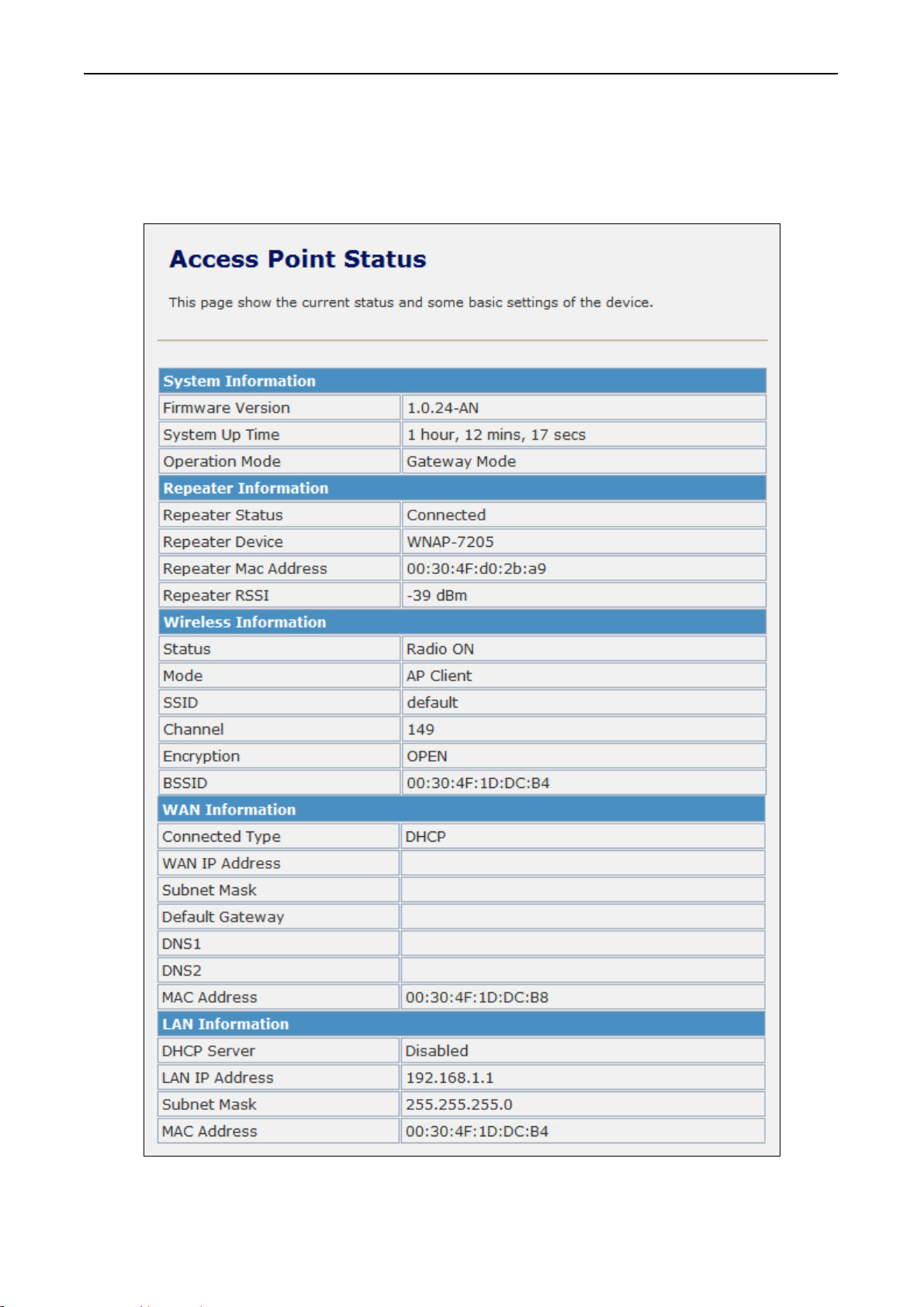
User’s Manual of WNAP-7205
5.6.5 Status
This page shows the current status and some basic settings of the device, includes system information,
Repeater Information (Wireless Connection Status), Wireless Information (Wireless Configurations),
WAN Information (Internet Configurations), and LAN Information (Local Network).
Figure 5-48 Status - All
- 81 -
Page 82

5.6.6 System Log
This page is used to view the system logs.
Figure 5-49 System Log
The page includes the following fields:
User’s Manual of WNAP-7205
Refresh
Clear
Object Description
Click the Refresh button to refresh the log shown on the screen.
Click the Clear button to clear the log display screen.
- 82 -
Page 83

User’s Manual of WNAP-7205
Appendix A: FAQ
1. What and how to find my PC’s IP and MAC address?
IP address is the identifier for a computer or device on a TCP/IP network. Networks using the TCP/IP
protocol route messages based on the IP address of the destination. The format of an IP address is a
32-bit numeric address written as four numbers separated by periods. Each number can be zero to 255.
For example, 191.168.1.254 could be an IP address
The MAC (Media Access Control) address is your computer's unique hardware number. (On an
Ethernet LAN, it's the same as your Ethernet address.) When you're connected to the Internet from
your computer (or host as the Internet protocol thinks of it), a correspondence table relates your IP
address to your computer's physical (MAC) address on the LAN.
To find your PC’s IP and MAC address,
(1) Open the Command program in the Microsoft Windows.
(2) Type in “ipconfig /all”, then press the Enter button.
(3) Your PC’s IP address is the one entitled IP Address and your PC’s MAC address is the one
entitled Physical Address.
2. What is Wireless LAN?
A
wireless LAN (WLAN) is a network that allows access to Internet without the need for any wired
connections to the user’s machine.
3. What are ISM bands?
ands for Industrial, Scientific and Medical; radio frequency bands that the Federal
ISM st
Communications Commission (FCC) authorized for wireless LANs. The ISM bands are located at 915
+/-13 MHz, 2450 +/-50 MHz and 5800 +/-75 MHz.
4. How does wireless networking work?
The 802.
the wireless network consists of at least one access point connected to the wired network
infrastructure and a set of wireless end stations. This configuration is called a Basic Service Set (BSS).
An Extended Service Set (ESS) is a set of two or more BSSs forming a single sub-network. Since most
corporate WLANs require access to the wired LAN for services (file servers, printers, Internet links)
they will operate in infrastructure mode.
11 standard define two modes: infrastructure mode and ad hoc mode. In infrastructure mode,
- 83 -
Page 84

User’s Manual of WNAP-7205
Example 1: wireless Infrastructure Mode
Ad hoc mode (also called peer-to-peer mode or an Independent Basic Service Set, or IBSS) is simply a
set of 802.11 wireless stations that communicate directly with one another without using an access
point or any connection to a wired network. This mode is useful for quickly and easily setting up a
wireless network anywhere that a wireless infrastructure does not exist or is not required for services,
such as a hotel room, convention center, or airport, or where access to the wired network is barred
(such as for consultants at a client site).
Example 2: wireless Ad Hoc Mode
5. What is BSSID?
A
six-byte address is that distinguish a particular a particular access point from others. Also know as
just SSID. Serve as a network ID or name.
6. What is ESSID?
The Extended Service Set
ID (ESSID) is the name of the network you want to access. It is used to
identify different wireless networks.
7. What are potential factors that may causes interference?
Facto
rs of interference:
Obstacles: walls, ceilings, furniture… etc.
Building Materials: metal door, aluminum studs.
Electrical devices: microwaves, monitors and electrical motors.
- 84 -
Page 85

User’s Manual of WNAP-7205
Solutions to overcome the interferences:
Minimizing the number of walls and ceilings.
Position the WLAN antenna for best reception.
Keep WLAN devices away from other electrical devices, eg: microwaves, monitors, electric
motors…etc.
Add additional WLAN Access Points if necessary.
8. What are the Open System and Shared Key authentications?
IEEE 802.1
1 supports two subtypes of network authentication services: open system and shared key.
Under open system authentication, any wireless station can request authentication. The station that
needs to authenticate with another wireless station sends an authentication management frame that
contains the identity of the sending station. The receiving station then returns a frame that indicates
whether it recognizes the sending station. Under shared key authentication, each wireless station is
assumed to have received a secret shared key over a secure channel that is independent from the
802.11 wireless network communications channel.
9. What is WEP?
An option of IEEE 802.1
1 function is that offers frame transmission privacy similar to a wired network.
The Wired Equivalent Privacy generates secret shared encryption keys that both source and
destination stations can use to alert frame bits to avoid disclosure to eavesdroppers.
WEP relies on a secret key that is shared between a mobile station (e.g. a laptop with a wireless
Ethernet card) and an access point (i.e. a base station). The secret key is used to encrypt packets
before they are transmitted, and an integrity check is used to ensure that packets are not modified in
transit.
10. What is Fragment Threshold?
The proposed protocol uses the fram
e fragmentation mechanism defined in IEEE 802.11 to achieve
parallel transmissions. A large data frame is fragmented into several fragments each of size equal to
fragment threshold. By tuning the fragment threshold value, we can get varying fragment sizes. The
determination of an efficient fragment threshold is an important issue in this scheme. If the fragment
threshold is small, the overlap part of the master and parallel transmissions is large. This means the
spatial reuse ratio of parallel transmissions is high. In contrast, with a large fragment threshold, the
overlap is small and the spatial reuse ratio is low. However high fragment threshold leads to low
fragment overhead. Hence there is a trade-off between spatial re-use and fragment overhead.
Fragment threshold is the maximum packet size used for fragmentation. Packets larger than the size
programmed in this field will be fragmented.
If you find that your corrupted packets or asymmetric packet reception (all send packets, for example).
You may want to try lowering your fragmentation threshold. This will cause packets to be broken into
smaller fragments. These small fragments, if corrupted, can be resent faster than a larger fragment.
Fragmentation increases overhead, so you'll want to keep this value as close to the maximum value as
possible.
- 85 -
Page 86

User’s Manual of WNAP-7205
11. What is RTS (Request to Send) Threshold?
The RTS threshold is the packet size at which packet transmission is governed by the RTS/CTS
transaction. The IEEE 802.11-1997 standard allows for short packets to be transmitted without RTS/
CTS transactions. Each station can have a different RTS threshold. RTS/CTS is used when the data
packet size exceeds the defined RTS threshold. With the CSMA/CA transmission mechanism, the
transmitting station sends out an RTS packet to the receiving station, and waits for the receiving station
to send back a CTS (Clear to Send) packet before sending the actual packet data.
This setting is useful for networks with many clients. With many clients, and a high network load, there
will be many more collisions. By lowering the RTS threshold, there may be fewer collisions, and
performance should improve. Basically, with a faster RTS threshold, the system can recover from
problems faster. RTS packets consume valuable bandwidth, however, so setting this value too low will
limit performance.
12. What is Beacon Interval?
In addition to dat
a frames that carry information from higher layers, 802.11 include management and
control frames that support data transfer. The beacon frame, which is a type of management frame,
provides the "heartbeat" of a wireless LAN, enabling stations to establish and maintain
communications in an orderly fashion.
Beacon Interval represents the amount of time between beacon transmissions. Before a station enters
power save mode, the station needs the beacon interval to know when to wake up to receive the
beacon (and learn whether there are buffered frames at the access point).
13. What is Preamble Type?
There are two preamble types defined i
n IEEE 802.11 specification. A long preamble basically gives
the decoder more time to process the preamble. All 802.11 devices support a long preamble. The short
preamble is designed to improve efficiency (for example, for VoIP systems). The difference between
the two is in the Synchronization field. The long preamble is 128 bits, and the short is 56 bits.
14. What is SSID Broadcast?
Broad
cast of SSID is done in access points by the beacon. This announces your access point
(including various bits of information about it) to the wireless world around it. By disabling that feature,
the SSID configured in the client must match the SSID of the access point.
Some wireless devices don't work properly if SSID isn't broadcast (for example the D-link DWL-120
USB 802.11b adapter). Generally if your client hardware supports operation with SSID disabled, it's not
a bad idea to run that way to enhance network security. However it's no replacement for WEP, MAC
filtering or other protections.
- 86 -
Page 87

User’s Manual of WNAP-7205
15. What is Wi-Fi Protected Access (WPA)?
Wi-Fi’s original security mechanism, Wired Equivalent Privacy (WEP), has been viewed as insufficient
for securing confidential business communications. A longer-term solution, the IEEE 802.11i standard,
is under development. However, since the IEEE 802.11i standard is not expected to be published until
the end of 2003, several members of the WI-Fi Alliance teamed up with members of the IEEE 802.11i
task group to develop a significant near-term enhancement to Wi-Fi security. Together, this team
developed Wi-Fi Protected Access.
To upgrade a WLAN network to support WPA, Access Points will require a WPA software upgrade.
Clients will require a software upgrade for the network interface card, and possibly a software update
for the operating system. For enterprise networks, an authentication server, typically one that supports
RADIUS and the selected EAP authentication protocol, will be added to the network.
16. What is WPA2?
It is the seco
nd generation of WPA. WPA2 is based on the final IEEE 802.11i amendment to the 802.11
standard.
17. What is 802.1x Authentication?
802.1x is a framework for authenti
cated MAC-level access control, defines Extensible Authentication
Protocol (EAP) over LANs (WAPOL). The standard encapsulates and leverages much of EAP, which
was defined for dial-up authentication with Point-to-Point Protocol in RFC 2284.
Beyond encapsulating EAP packets, the 802.1x standard also defines EAPOL messages that convey
the shared key information critical for wireless security.
18. What is Temporal Key Integrity Protocol (TKIP)?
The
Temporal Key Integrity Protocol, pronounced tee-kip, is part of the IEEE 802.11i encryption
standard for wireless LANs. TKIP is the next generation of WEP, the Wired Equivalency Protocol,
which is used to secure 802.11 wireless LANs. TKIP provides per-packet key mixing, a message
integrity check and a re-keying mechanism, thus fixing the flaws of WEP.
19. What is Advanced Encryption Standard (AES)?
Sec
urity issues are a major concern for wireless LANs, AES is the U.S. government’s next-generation
cryptography algorithm, which will replace DES and 3DES.
20. What is Inter-Access Point Proto
col (IAPP)?
The IEEE 802.11f Inter-Access Point Protocol (IAPP) supports Access Point Vendor interoperability,
enabling roaming of 802.11 Stations within IP subnet.
IAPP defines messages and data to be exchanged between Access Points and between the IAPP and
high layer management entities to support roaming. The IAPP protocol uses TCP for inter-Access
- 87 -
Page 88

User’s Manual of WNAP-7205
Point communication and UDP for RADIUS request/response exchanges. It also uses Layer 2 frames
to update the forwarding tables of Layer 2 devices.
21. What is Wireless Distribu
tion System (WDS)?
The Wireless Distribution System feature allows WLAN AP to talk directly to other APs via wireless
channel, like the wireless WDS or repeater service.
22. What is Universal Plug and Play (UPnP)?
UPnP
is an open networking architecture that consists of services, devices, and control points. The
ultimate goal is to allow data communication among all UPnP devices regardless of media, operating
system, programming language, and wired/wireless connection.
23. What is Maximum Transmission Unit (MTU) Size?
Maximum
Transmission Unit (MTU) indicates the network stack of any packet is larger than this value
will be fragmented before the transmission. During the PPP negotiation, the peer of the PPP
connection will indicate its MRU and will be accepted. The actual MTU of the PPP connection will be
set to the smaller one of MTU and the peer’s MRU.
24. What is Clone MAC Address?
Clon
e MAC address is designed for your special application that request the clients to register to a
server machine with one identified MAC address. Since that all the clients will communicate outside
world through the WLAN Broadband Router, so have the cloned MAC address set on the WLAN
Broadband Router will solve the issue.
25. What is DDNS?
DDNS is the
abbreviation of Dynamic Domain Name Server. It is designed for user owned the DNS
server with dynamic WAN IP address.
26. What is NTP Client?
NTP
client is designed for fetching the current timestamp from internet via Network Time protocol. User
can specify time zone, NTP server IP address.
27. What is VPN?
VPN is the ab
breviation of Virtual Private Network. It is designed for creating point-to point private link
via shared or public network.
28. What is IPSEC?
IPSEC is the abbreviation
of IP Security. It is used to transferring data securely under VPN.
- 88 -
Page 89

User’s Manual of WNAP-7205
29. What is WLAN Block Relay between Clients?
An Infrastructure Basic Service Set is a BSS with a component called an Access Point (AP). The
access point provides a local relay function for the BSS. All stations in the BSS communicate with the
access point and no longer communicate directly. All frames are relayed between stations by the
access point. This local relay function effectively doubles the range of the IBSS.
30. What is WMM?
WMM is b
ased on a subset of the IEEE 802.11e WLAN QoS draft standard. WMM adds prioritized
capabilities to Wi-Fi networks and optimizes their performance when multiple concurring applications,
each with different latency and throughput requirements, compete for network resources. By using
WMM, end-user satisfaction is maintained in a wider variety of environments and traffic conditions.
WMM makes it possible for home network users and enterprise network managers to decide which
data streams are most important and assign them a higher traffic priority.
31. What is WLAN ACK TIMEOUT?
ACK frame h
as to receive ACK timeout frame. If remote does not receive in specified period, it will be
retransmitted.
32. What is Modulation Coding Scheme (MCS)?
MCS is Wirel
ess link data rate for 802.11n. The throughput/range performance of an AP will depend on
its implementation of coding schemes. MCS includes variables such as the number of spatial streams,
modulation, and the data rate on each stream. Radios establishing and maintaining a link must
automatically negotiate the optimum MCS based on channel conditions and then continuously adjust
the selection of MCS as conditions change due to interference, motion, fading, and other events.
33. What is Frame Aggregation?
Every 802.1
1 packet, no matter how small, has a fixed amount of overhead associated with it. Frame
Aggregation combines multiple smaller packets together to form one larger packet. The larger packet
can be sent without the overhead of the individual packets. This technique helps improve the efficiency
of the 802.11n radio allowing more end user data to be sent in a given time.
34. What is Guard Intervals (GI)?
A
GI is a period of time between symbol transmission that allows reflections (from multipath) from the
previous data transmission to settle before transmitting a new symbol. The 802.11n specifies two
guard intervals: 400ns (short) and 800ns (long). Support of the 400ns GI is optional for transmit and
receive. The purpose of a guard interval is to introduce immunity to propagation delays, echoes, and
reflections to which digital data is normally very sensitive.
- 89 -
Page 90

User’s Manual of WNAP-7205
Appendix B: Configuration Example
1. Example – PPPoE on the WAN
Sales division of Company ABC likes to establish a WLAN network to support mobile communication
on sales’ Notebook PCs. MIS engineer collects information and plans the WLAN Broadband Router
implementation by the following configuration.
WAN configuration:PPPoE
User Name
Password
Note: User Name and password that ISP provided.
LAN configuration:
IP Address
Subnet Mask
DHCP Client Range
WLAN configuration:
SSID
Channel Number
1) Configure the WAN interface:
Open “Wide Area Network (WAN) Settings” page, select PPPoE then enter the User Name
“user123” and Password “password123”, the password is encrypted to display on the screen.
user123
password123
10.10.10.254
255.255.255.0
10.10.10.100 – 10.10.10.200
AP
AutoSelect
Press “Apply” button to confirm the configuration setting.
- 90 -
Page 91

User’s Manual of WNAP-7205
2) Configure the LAN interface:
Open “Local Area Network (LAN) settings” page, enter the IP Address “10.10.10.254”, Subnet
Mask “255.255.255.0”.
Enable DHCP Server, DHCP client range “10.10.10.100” to “10.10.10.200”, default Gateway
“10.10.10.254” .
Press “Apply” button to confirm the configuration setting.
- 91 -
Page 92

User’s Manual of WNAP-7205
3) Configure the WLAN interface:
Open “Basic Wireless Settings” page, enter the SSID ”AP”, Channel Number ”AutoSelect”.
Press “Apply” button to confirm the configuration setting.
- 92 -
Page 93

User’s Manual of WNAP-7205
- 93 -
Page 94

User’s Manual of WNAP-7205
2. Example – fixed IP on the WAN
Company ABC likes to establish a WLAN network to support mobile communication on all employees’
Notebook PCs. MIS engineer collects information and plans the WLAN Broadband Router
implementation by the following configuration.
WAN configuration : Fixed IP
IP Address 192.168.20.254
Subnet Mask 255.255.255.0
Default Gateway 192.168.20.1
Primary DNS Address 168.95.1.1
LAN configuration:
IP Address 10.10.10.254
Subnet Mask 255.255.255.0
DHCP Client Range 10.10.10.100 – 10.10.10.200
WLAN configuration:
SSID AP
Channel Number AutoSelect
1) Configure the WAN interface:
Open “Wide Area Network (WAN) Settings” page, select STATIC(fixed IP) then enter IP Address
“192.168.20.254”, subnet mask “255.255.255.0”, Default gateway “192.168.20.1”.
Press “Apply” button to confirm the configuration setting.
- 94 -
Page 95
User’s Manual of WNAP-7205
2) Configure the LAN interface:
Open “Local Area Network (LAN) settings” page, enter the IP Address “10.10.10.254”, Subnet
Mask “255.255.255.0”.
Enable DHCP Server, DHCP client range “10.10.10.100” to “10.10.10.200”, default Gateway
“10.10.10.254” .
Press “Apply” button to confirm the configuration setting.
- 95 -
Page 96

User’s Manual of WNAP-7205
3) Configure the WLAN interface:
Open “Basic Wireless Settings” page, enter the SSID ”AP”, Channel Number ”AutoSelect”.
Press “Apply” button to confirm the configuration setting.
- 96 -
Page 97

User’s Manual of WNAP-7205
- 97 -
Page 98

User’s Manual of WNAP-7205
3. Example – set WLAN to be WAN as WiFi Client
User Mr. ABC likes to configure this WLAN Broadband Router to be a WiFi client. In order to
communicate with another AP. Mr. ABC collects information and plans the WLAN Broadband Router
implementation by the following configuration.
WiFi client:
WAN configuration: DHCP (Auto config)
IP Address
Subnet Mask
Default Gateway
Primary DNS Address
LAN configuration:
IP Address
Subnet Mask
DHCP Client Range
WLAN configuration:
SSID Depend on AP
Channel Number Depend on AP
WiFi server:
10.10.10.100 – 10.10.10.200
n/a
n/a
n/a
n/a
10.10.10.254
255.255.255.0
AP configuration:
SSID WNAP-7205
Channel Number 149
Wireless Encryption WPA2
DHCP server
1) Configure the Operation Mode:
Open “Operation Mode Configuration” page, select Wireless ISP, then click “Apply” button to
confirm the configuration setting and reboot the WLAN Broadband Router. After reboot, the wireless
LAN will become to WAN interface.
192.168.1.2
– 192.168.1.254
- 98 -
Page 99

User’s Manual of WNAP-7205
2) Site Survey:
Open “Site Survey” page under Wireless Settings, and select the AP “WNAP-7205”.
Press “Next” button to connect with the AP.
3) Wireless encryption setting:
If the AP has encryption setting, it will pop out a window for you filling the encryption setting.
Please fill up the encryption code and click “Apply” button to connect with the AP.
5) Status:
After connected with AP, you can open “Status” page under Administration to check Link Status and
Internet Configurations.
- 99 -
Page 100

User’s Manual of WNAP-7205
- 100 -
 Loading...