

Page 1

WGSW-48000
User’s Manual of WGSW-48000
User’s Manual
48-Port 10/100/1000Mbps with
4 Shared SFP
Layer 2 Managed Ethernet Switch
1
Page 2

User’s Manual of WGSW-48000
Trademarks
Copyright © PLANET Technology Corp. 2009.
Contents subject to which revision without prior notice.
PLANET is a registered trademark of PLANET Technology Corp. All other trademarks belong to their respective owners.
Disclaimer
PLANET Technology does not warrant that the hardware will work properly in all environments and applications, and makes no
warranty and representation, either implied or expressed, with respect to the quality, performance, merchantability, or fitness for
a particular purpose. PLANET has made every effort to ensure that this User's Manual is accurate; PLANET disclaims liability
for any inaccuracies or omissions that may have occurred.
Information in this User's Manual is subject to change without notice and does not represent a commitment on the part of
PLANET. PLANET assumes no responsibility for any inaccuracies that may be contained in this User's Manual. PLANET makes
no commitment to update or keep current the information in this User's Manual, and reserves the right to make improvements to
this User's Manual and/or to the products described in this User's Manual, at any time without notice.
If you find information in this manual that is incorrect, misleading, or incomplete, we would appreciate your comments and
suggestions.
FCC Warning
This equipment has been tested and found to comply with the limits for a Class A digital device, pursuant to Part 15 of the FCC
Rules. These limits are designed to provide reasonable protection against harmful interference when the equipment is operated
in a commercial environment. This equipment generates, uses, and can radiate radio frequency energy and, if not installed and
used in accordance with the Instruction manual, may cause harmful interference to radio communications. Operation of this
equipment in a residential area is likely to cause harmful interference in which case the user will be required to correct the
interference at whose own expense.
CE Mark Warning
This is a Class A product. In a domestic environment, this product may cause radio interference, in which case the user may be
required to take adequate measures.
WEEE Warning
To avoid the potential effects on the environment and human health as a result of the presence of
hazardous substances in electrical and electronic equipment, end users of electrical and electronic
equipment should understand the meaning of the crossed-out wheeled bin symbol. Do not dispose of
WEEE as unsorted municipal waste and have to collect such WEEE separately.
Revision
PLANET 48-Port 10/100/1000Mbps with 4 Shared SFP Combo Managed Switch User's Manual
FOR MODEL: WGSW-48000
REVISION: 1.0 (APRIL.2009)
Part No: EM-WGSW-48000 (2081-A93180-000)
2
Page 3

User’s Manual of WGSW-48000
TABLE OF CONETNTS
1. INTRODUTION .................................................................................................................... 20
1.1 Packet Contents .........................................................................................................................................20
1.2 Product Description ...................................................................................................................................20
1.3 How to Use This Manual ............................................................................................................................21
1.4 Product Features........................................................................................................................................23
1.5 Product Specification ................................................................................................................................25
2. INSTALLATION ................................................................................................................... 27
2.1 Hardware Description ................................................................................................................................27
2.1.1 Switch Front Panel ..............................................................................................................................................27
2.1.2 LED Indications ...................................................................................................................................................28
2.1.3 Switch Rear Panel ...............................................................................................................................................29
2.2 Install the Switch ........................................................................................................................................30
2.2.1 Desktop Installation .............................................................................................................................................30
2.2.2 Rack Mounting.....................................................................................................................................................31
2.2.3 Installing the SFP transceiver ..............................................................................................................................32
3. SWITCH MANAGEMENT .................................................................................................... 35
3.1 Requirements..............................................................................................................................................35
3.2 Management Access Overview.................................................................................................................36
3.3 Administration Console.............................................................................................................................36
3.4 Web Management.......................................................................................................................................38
3.5 SNMP-Based Network Management.........................................................................................................39
3.6 Protocols.....................................................................................................................................................40
3.6.1 Virtual Terminal Protocols....................................................................................................................................40
3.6.2 SNMP Protocol ....................................................................................................................................................40
3.6.3 Management Architecture....................................................................................................................................40
4. WEB CONFIGURATION...................................................................................................... 41
4.1 Main WEB PAGE.........................................................................................................................................44
4.2 System.........................................................................................................................................................46
3
Page 4

User’s Manual of WGSW-48000
4.2.1 System Information..............................................................................................................................................46
4.2.2 Network Management .........................................................................................................................................47
4.2.3 Time Setting.........................................................................................................................................................48
4.2.4 Green Ethernet ....................................................................................................................................................49
4.3 Port Management .......................................................................................................................................50
4.3.1 Port Configuration................................................................................................................................................50
4.3.2 LACP Property.....................................................................................................................................................52
4.3.3 LAG Group ..........................................................................................................................................................55
4.4 VLAN............................................................................................................................................................56
4.4.1 VLAN Overview ...................................................................................................................................................56
4.4.2 IEEE 802.1Q VLAN .............................................................................................................................................56
4.4.3 Create VLAN .......................................................................................................................................................61
4.4.4 VLAN Setting .......................................................................................................................................................62
4.4.5 VLAN Port............................................................................................................................................................64
4.4.6 GVRP ..................................................................................................................................................................65
4.5 Spanning Tree.............................................................................................................................................67
4.5.1 RSTP (Rapid Spanning Tree Protocol) ................................................................................................................73
4.5.2 RSTP Port ...........................................................................................................................................................74
4.5.3 MSTP...................................................................................................................................................................75
4.5.4 MSTP Port ...........................................................................................................................................................76
4.5.5 MSTP Instance ....................................................................................................................................................77
4.5.6 MSTP Interface....................................................................................................................................................78
4.6 Multicast ......................................................................................................................................................80
4.6.1 IGMP Snooping ...................................................................................................................................................80
4.6.2 Static Multicast.....................................................................................................................................................84
4.6.3 Static Multicast Table ...........................................................................................................................................84
4.6.4 IGMP ...................................................................................................................................................................86
4.7 Security .......................................................................................................................................................87
4.7.1 Port Security ........................................................................................................................................................87
4.7.2 ACL......................................................................................................................................................................88
4.7.3 802.1x..................................................................................................................................................................92
4.7.3.1 Understanding IEEE 802.1X Port-Based Authentication ...........................................................................93
4.7.3.2 802.1x Port Configuration..........................................................................................................................96
4.7.3.3 Windows Platform RADIUS Server Configuration .....................................................................................97
4.7.3.4 802.1X Client Configuration.......................................................................................................................99
4.7.4 RADIUS .............................................................................................................................................................101
4.7.5 TACACS+ ..........................................................................................................................................................102
4.7.6 Storm Control.....................................................................................................................................................104
4
Page 5

User’s Manual of WGSW-48000
4.7.7 Management IP List...........................................................................................................................................105
4.7.8 Auto DoS ...........................................................................................................................................................106
4.7.9 SSH ...................................................................................................................................................................107
4.7.10 DHCP Snooping ..............................................................................................................................................108
4.7.11 Dynamic ARP Inspection .................................................................................................................................109
4.7.12 IP Source Guard..............................................................................................................................................110
4.7.13 HTTPS............................................................................................................................................................. 11 2
4.8 Quality of Service ..................................................................................................................................... 113
4.8.1 Understand QOS ............................................................................................................................................... 11 3
4.8.2 Queue Settings..................................................................................................................................................114
4.8.2 DSCP................................................................................................................................................................. 114
4.8.3 802.1P ...............................................................................................................................................................117
4.8.4 Port-Based QoS ................................................................................................................................................119
4.8.5 Rate Control ......................................................................................................................................................120
4.8.6 DSCP Remark ...................................................................................................................................................121
4.9 SNMP .........................................................................................................................................................122
SNMP Overview .........................................................................................................................................................122
4.9.1 SNMP ................................................................................................................................................................123
4.9.2 Group Profile .....................................................................................................................................................124
4.9.3 User Profile........................................................................................................................................................125
4.9.4 Community Profile .............................................................................................................................................127
4.9.5 SNMP Trap Station ............................................................................................................................................128
4.10 LLDP ........................................................................................................................................................129
4.10.1 LLDP Settings..................................................................................................................................................129
4.10.2 LLDP Statistics.................................................................................................................................................130
4.10.3 Local Information .............................................................................................................................................131
4.10.4 Remote Information .........................................................................................................................................134
4.11 ADMIN......................................................................................................................................................135
4.11.1 Admin Password ..............................................................................................................................................135
4.11.2 L2 Table ...........................................................................................................................................................136
4.11.3 Static Address ..................................................................................................................................................137
4.11.4 Port Mirroring ...................................................................................................................................................138
4.11.5 Admin Timeout .................................................................................................................................................139
4.11.6 Firmware Upgrade ...........................................................................................................................................140
4.11.7 Reboot .............................................................................................................................................................141
4.11.8 Save Configurations.........................................................................................................................................143
4.11.9 Logs Settings ...................................................................................................................................................146
4.11.10 Log Server .....................................................................................................................................................146
4.11.11 Memory Logs .................................................................................................................................................148
5
Page 6

User’s Manual of WGSW-48000
4.11.12 Flash Logs .....................................................................................................................................................149
4.11.13 Ping Function .................................................................................................................................................150
4.11.14 Cable Diagnostic............................................................................................................................................150
4.11.15 DHCP Relay...................................................................................................................................................152
4.11.16 DHCP Option 82 ............................................................................................................................................152
4.11.17 Self Loop Detection........................................................................................................................................153
4.11.18 BOOTP Configure Download .........................................................................................................................154
4.12 Statistics..................................................................................................................................................155
4.12.1 802.1X Statistic................................................................................................................................................155
4.12.2 RMON Statistic ................................................................................................................................................156
4.12.3 RMON Event ...................................................................................................................................................158
4.12.4 RMON Event Log ............................................................................................................................................159
4.12.5 RMON Alarm ...................................................................................................................................................160
4.12.6 RMON History .................................................................................................................................................162
5. COMMAND LINE INTERFACE.......................................................................................... 164
5.1 Accessing the CLI ....................................................................................................................................164
Logon to the Console ..........................................................................................................................................164
Configure IP address...........................................................................................................................................165
5.2 Telnet login................................................................................................................................................167
6. COMMAND LINE MODE ................................................................................................... 168
6.1 User Mode commands .............................................................................................................................169
help .....................................................................................................................................................................169
logout ..................................................................................................................................................................169
ping .....................................................................................................................................................................169
show port.............................................................................................................................................................170
show network ......................................................................................................................................................170
show system........................................................................................................................................................170
show port statistics ..............................................................................................................................................170
enable..................................................................................................................................................................171
Save ....................................................................................................................................................................171
6.2 Privileged Mode commands....................................................................................................................171
cable-diag port.....................................................................................................................................................171
6.2.1 Clear Command ................................................................................................................................................172
clear arl dynamic .................................................................................................................................................172
clear arl static mac...............................................................................................................................................172
clear config ..........................................................................................................................................................172
6
Page 7

User’s Manual of WGSW-48000
clear counters......................................................................................................................................................172
clear igmpsnooping .............................................................................................................................................173
clear static-mcast ................................................................................................................................................173
clear pass ............................................................................................................................................................173
clear lacp .............................................................................................................................................................173
clear logs .............................................................................................................................................................173
clear vlan .............................................................................................................................................................174
configuration........................................................................................................................................................174
6.2.2 Copy Command.................................................................................................................................................174
copy nvram_config tftp ........................................................................................................................................174
copy system_image tftp.......................................................................................................................................174
copy tftp...............................................................................................................................................................175
exit.......................................................................................................................................................................175
help .....................................................................................................................................................................175
logout ..................................................................................................................................................................176
ping .....................................................................................................................................................................176
reload ..................................................................................................................................................................176
save.....................................................................................................................................................................176
6.2.3 Show Command ................................................................................................................................................177
show qos .............................................................................................................................................................177
show qos cos.......................................................................................................................................................177
show qos queue-settings.....................................................................................................................................177
show qos advanced.............................................................................................................................................177
show qos advanced mode...................................................................................................................................177
show qos advanced dscp ....................................................................................................................................177
show qos advanced ip-precedence .....................................................................................................................178
show qos port-based ...........................................................................................................................................178
show qos port-based port ....................................................................................................................................178
show qos port-based all.......................................................................................................................................178
show dot1x ..........................................................................................................................................................178
show dot1x config................................................................................................................................................179
show dot1x radius ...............................................................................................................................................179
show dot1x statistics............................................................................................................................................179
show igmpsnooping.............................................................................................................................................179
show igmpsnooping dynamic_router_port...........................................................................................................179
show igmpsnooping groups.................................................................................................................................180
show igmpsnooping info......................................................................................................................................180
show lag ..............................................................................................................................................................180
show lag lag-index...............................................................................................................................................180
show lag all..........................................................................................................................................................180
show lldp .............................................................................................................................................................181
7
Page 8

User’s Manual of WGSW-48000
show lldp statistic.................................................................................................................................................181
show lldp local .....................................................................................................................................................181
show lldp msap....................................................................................................................................................181
show lldp msap-entry...........................................................................................................................................181
show logging .......................................................................................................................................................182
show logging memory-log....................................................................................................................................182
show logging flash-log.........................................................................................................................................182
show monitor .......................................................................................................................................................182
show network ......................................................................................................................................................182
show port.............................................................................................................................................................183
show port port-index............................................................................................................................................183
show port all ........................................................................................................................................................183
show port-security ...............................................................................................................................................183
show port-security port ........................................................................................................................................183
show port-security all...........................................................................................................................................183
show rate-limit .....................................................................................................................................................184
show rate-limit port ..............................................................................................................................................184
show rate-limit all.................................................................................................................................................184
show running-config ............................................................................................................................................184
show snmp ..........................................................................................................................................................185
show snmp groups ..............................................................................................................................................185
show snmp users ................................................................................................................................................185
show snmp communities .....................................................................................................................................185
show snmp info ...................................................................................................................................................185
show sntp ............................................................................................................................................................186
show spanning-tree .............................................................................................................................................186
show spanning-tree interface ..............................................................................................................................186
show spanning-tree interface port .......................................................................................................................186
show spanning-tree interface all..........................................................................................................................186
show spanning-tree mst ......................................................................................................................................186
show spanning-tree mst detailed.........................................................................................................................187
show spanning-tree mst instance ........................................................................................................................187
show spanning-tree mst summary.......................................................................................................................187
show spanning-tree status...................................................................................................................................187
show storm-control ..............................................................................................................................................188
show sysinfo........................................................................................................................................................188
show switch.........................................................................................................................................................188
show switch admin-time ......................................................................................................................................188
show switch age-time ..........................................................................................................................................188
show switch mac-table ........................................................................................................................................189
show switch mac-table all....................................................................................................................................189
8
Page 9

User’s Manual of WGSW-48000
show switch mac-table vlan.................................................................................................................................189
show switch mac-table port .................................................................................................................................189
show switch mcast-table......................................................................................................................................189
show switch mac .................................................................................................................................................190
show trapflags .....................................................................................................................................................190
show vlan ............................................................................................................................................................190
show vlan member ..............................................................................................................................................190
show vlan number ...............................................................................................................................................190
show rmon...........................................................................................................................................................191
show rmon event Index .......................................................................................................................................191
show rmon event .................................................................................................................................................191
Show rmon event log event _index .....................................................................................................................191
show rmon alarm index .......................................................................................................................................191
show rmon alarm.................................................................................................................................................192
show rmon history ...............................................................................................................................................192
show rmon history index......................................................................................................................................192
show rmon history ...............................................................................................................................................192
show rmon statistics ............................................................................................................................................193
show poe port-index ............................................................................................................................................193
show poe all ........................................................................................................................................................193
show poe system-status......................................................................................................................................193
show tacplus........................................................................................................................................................194
show arp..............................................................................................................................................................194
show acl ..............................................................................................................................................................194
show dhcpsnooping config ..................................................................................................................................194
show dhcpsnooping port......................................................................................................................................194
show dhcpsnooping vlan .....................................................................................................................................195
show dhcpsnooping database .............................................................................................................................195
show dhcpsnooping database all.........................................................................................................................195
show dhcpsnooping database static....................................................................................................................195
show dhcpsnooping database dynamic...............................................................................................................195
show ipsrcgd config.............................................................................................................................................196
show ipsrcgd ports...............................................................................................................................................196
show ipsrcgd database........................................................................................................................................196
show https ...........................................................................................................................................................196
show loop_detect ................................................................................................................................................196
telnet ...................................................................................................................................................................197
6.3 Global Config mode commands .............................................................................................................198
exit.......................................................................................................................................................................198
6.3.1 VLAN Command................................................................................................................................................198
9
Page 10

User’s Manual of WGSW-48000
vlan add...............................................................................................................................................................198
vlan add number..................................................................................................................................................198
vlan add range.....................................................................................................................................................198
vlan delete ...........................................................................................................................................................199
vlan port...............................................................................................................................................................199
vlan port all ..........................................................................................................................................................199
vlan port all port-configure...................................................................................................................................199
vlan port all protected ..........................................................................................................................................199
vlan port all pvid ..................................................................................................................................................200
vlan port ports......................................................................................................................................................200
vlan port ports port-configure...............................................................................................................................200
vlan port ports protected......................................................................................................................................200
vlan port ports pvid ..............................................................................................................................................200
vlan lag................................................................................................................................................................201
vlan lag vlan < vlan-id> exclude ..........................................................................................................................201
vlan lag vlan <vlan-ID> untagged ........................................................................................................................201
vlan lag vlan <vlan-ID> tagged ............................................................................................................................201
Bridge aging-time ................................................................................................................................................202
6.3.2 Link Aggregation Command ...............................................................................................................................202
lacp-syspri system-priority ...................................................................................................................................202
link-aggregation...................................................................................................................................................202
link-aggregation addport......................................................................................................................................202
link aggregation delport .......................................................................................................................................203
Link Aggregation delport all .................................................................................................................................203
link aggregation delport lag .................................................................................................................................203
6.3.3 LLDP Command ................................................................................................................................................203
lldp enable ...........................................................................................................................................................203
lldp disable ..........................................................................................................................................................203
lldp adv-interval ...................................................................................................................................................204
lldp fast-startcnt ...................................................................................................................................................204
lldp hold...............................................................................................................................................................204
lldp notify-interval ................................................................................................................................................204
lldp reinit-delay ....................................................................................................................................................205
lldp tx-delay .........................................................................................................................................................205
lldp mgmt-addrtxport............................................................................................................................................205
6.3.4 Log Command ...................................................................................................................................................206
log .......................................................................................................................................................................206
log log-server.......................................................................................................................................................206
log log-server name <WORD>add ......................................................................................................................206
log log-server name <word> delete .....................................................................................................................206
log logging-target.................................................................................................................................................206
log logging-target memory...................................................................................................................................207
10
Page 11

User’s Manual of WGSW-48000
log logging-target flash ........................................................................................................................................207
log logging-target console ...................................................................................................................................207
log logging-target server name <WORD>............................................................................................................207
radius-server ip....................................................................................................................................................208
static-address add ...............................................................................................................................................208
static-address delete ...........................................................................................................................................208
6.3.5 Mgmt Command ................................................................................................................................................209
mgmt-accesslist ipaddr........................................................................................................................................209
mgmt-accesslist enable .......................................................................................................................................209
mgmt-accesslist disable ......................................................................................................................................209
6.3.6 Monitor Command .............................................................................................................................................209
monitor enable.....................................................................................................................................................209
monitor disable ....................................................................................................................................................210
monitor des..........................................................................................................................................................210
monitor des <port-ID> probetype bidirection .......................................................................................................210
monitor des <port-ID> probetype ingress ............................................................................................................ 210
monitor des <port-ID> probetype egress ............................................................................................................. 211
6.3.7 dot1x Command ................................................................................................................................................ 211
dot1x enable........................................................................................................................................................ 211
dot1x disable ....................................................................................................................................................... 211
dot1x port-control ................................................................................................................................................211
dot1x port-control enable port..............................................................................................................................212
dot1x port-control disable port .............................................................................................................................212
6.3.8 network Command ............................................................................................................................................212
network mgmt-vlan ..............................................................................................................................................212
network parms.....................................................................................................................................................213
network protocol ..................................................................................................................................................213
network dhcp-relay ..............................................................................................................................................213
network dhcp-relay mode ....................................................................................................................................213
network dhcp-relay server ...................................................................................................................................213
network dhcp-relay vlan.......................................................................................................................................214
network dhcp-relay vlan <vlan-ID> add ...............................................................................................................214
network dhcp-relay vlan <vlan-ID> remove .........................................................................................................214
network sysinfo....................................................................................................................................................214
Network sysinfo sysname....................................................................................................................................214
network sysinfo syslocate....................................................................................................................................215
network sysinfo syscontact..................................................................................................................................215
network admin-timeout ........................................................................................................................................215
6.3.9 Port Command ..................................................................................................................................................215
port-all admin-mode ............................................................................................................................................215
port-all auto-negotiate .........................................................................................................................................216
11
Page 12

User’s Manual of WGSW-48000
port-all flow-control ..............................................................................................................................................216
port-all portsec-lockmode ....................................................................................................................................216
port-all portsec-lockmode none ...........................................................................................................................216
port-all portsec-lockmode dynamic max-entries ..................................................................................................217
port-all rate-limit...................................................................................................................................................217
port-all rate-limit egress .......................................................................................................................................217
port-all rate-limit ingress ......................................................................................................................................217
port-all rmon-counter ...........................................................................................................................................217
port-all speed.......................................................................................................................................................218
port-all storm-control ...........................................................................................................................................218
port-all storm-control disable ...............................................................................................................................218
port-all storm-control broadcast...........................................................................................................................218
port-all storm-control broadcast-multicast............................................................................................................219
port-all storm-control broadcast-unknown ...........................................................................................................219
port-all storm-control all-cast ...............................................................................................................................219
6.3.10 QoS Command................................................................................................................................................219
qos qos-advanced ...............................................................................................................................................219
qos qos-advanced DSCP ....................................................................................................................................220
qos qos-advanced ip_precedence.......................................................................................................................220
qos qos-advanced none ......................................................................................................................................220
qos cos priority ....................................................................................................................................................220
qos dscp ..............................................................................................................................................................220
qos port-based port <WORD>status ...................................................................................................................221
qos scheduling ....................................................................................................................................................221
qos scheduling strict............................................................................................................................................221
qos scheduling wrr ..............................................................................................................................................221
qos ip-precedence...............................................................................................................................................222
qos wrr weight .....................................................................................................................................................222
qos dscp-remark acl_entry_name .......................................................................................................................222
6.3.11 Set Commang..................................................................................................................................................223
set IGMP .............................................................................................................................................................223
set igmp enable ...................................................................................................................................................223
set igmp disable ..................................................................................................................................................223
set igmp last-memberquery .................................................................................................................................223
set igmp last-membercount .................................................................................................................................223
set igmp query-interval ........................................................................................................................................224
set igmp query-resinterval ...................................................................................................................................224
set igmp robustness ............................................................................................................................................224
set igmp router-port ports ....................................................................................................................................224
set igmp-querier ..................................................................................................................................................225
set igmp-proxy.....................................................................................................................................................225
12
Page 13

User’s Manual of WGSW-48000
set static-mcast ...................................................................................................................................................225
set static-mcast name <WORD> add vid.............................................................................................................225
set static-mcast name <WORD>delete ...............................................................................................................226
6.3.12 SNMP Command.............................................................................................................................................226
snmp notify ..........................................................................................................................................................226
snmp group add ..................................................................................................................................................226
snmp group delete...............................................................................................................................................227
snmp user add.....................................................................................................................................................227
snmp user delete.................................................................................................................................................227
snmp community add ..........................................................................................................................................228
snmp community delete.......................................................................................................................................228
snmp trapstation add <ip-addr> community <community name> type bootup trap-version.................................228
snmp trapstation add <ip-addr> community <community name> type linkchange trap-version .......................... 229
snmp trapstation add <ip-addr> community <community name> type both trap-version..................................... 229
snmp trapstation add <ip-addr> community <community name> type none trap-version....................................229
snmp trapstation delete .......................................................................................................................................229
6.3.13 SNTP Command..............................................................................................................................................230
sntp daylight ........................................................................................................................................................230
sntp localtime ......................................................................................................................................................230
sntp localtime enable...........................................................................................................................................230
sntp localtime localtime_date ..............................................................................................................................230
sntp server enable...............................................................................................................................................231
sntp server ipaddr................................................................................................................................................231
sntp server polling ...............................................................................................................................................231
sntp timezone ......................................................................................................................................................231
6.3.14 Spanning-tree Command.................................................................................................................................232
spanning-tree forceversion ..................................................................................................................................232
spanning-tree forceversion 8021s .......................................................................................................................232
spanning-tree forceversion 8021w ......................................................................................................................232
spanning-tree forceversion none .........................................................................................................................232
spanning-tree configuration .................................................................................................................................233
spanning-tree configuration name .......................................................................................................................233
spanning-tree configuration revision....................................................................................................................233
spanning-tree forward-time..................................................................................................................................233
spanning-tree max-age........................................................................................................................................233
spanning-tree max-hops......................................................................................................................................234
spanning-tree port ...............................................................................................................................................234
spanning-tree port all...........................................................................................................................................234
spanning-tree port cost........................................................................................................................................234
spanning-tree port priority....................................................................................................................................235
spanning-tree port edge ......................................................................................................................................235
13
Page 14

User’s Manual of WGSW-48000
spanning-tree port force-p2plink..........................................................................................................................235
spanning-tree port migration-check .....................................................................................................................235
spanning-tree port root-guard..............................................................................................................................236
spanning-tree priority...........................................................................................................................................236
spanning-tree mst................................................................................................................................................236
spanning-tree mst instance .................................................................................................................................236
spanning-tree mst instance add vlan...................................................................................................................236
spanning-tree mst instance delete.......................................................................................................................237
spanning-tree mst vlan ........................................................................................................................................237
spanning-tree mst vlan <MST ID> <vlan list> add...............................................................................................237
Spanning-Tree mst vlan <MST ID> <vlan list> delete..........................................................................................237
spanning-tree mst bridgepri.................................................................................................................................238
spanning-tree mst cost ........................................................................................................................................238
spanning-tree mst priority ....................................................................................................................................238
user password .....................................................................................................................................................238
Interface ..............................................................................................................................................................239
6.3.15 RMON Command ............................................................................................................................................239
rmon ....................................................................................................................................................................239
rmon event index.................................................................................................................................................239
rmon alarm index.................................................................................................................................................239
rmon del ..............................................................................................................................................................240
rmon del event index ...........................................................................................................................................240
rmon del alarm index ...........................................................................................................................................240
6.3.16 Access list Command ......................................................................................................................................240
access-list name <WORD> add priority...............................................................................................................240
access-list name <WORD> action.......................................................................................................................241
access-list name <WORD> action deny..............................................................................................................241
access-list name <WORD> action permit............................................................................................................241
access-list name <WORD> clear ........................................................................................................................241
access-list name <WORD> clears SRC IP..........................................................................................................241
access-list name <WORD> clears DST IP ..........................................................................................................242
access-list name <WORD> clear L4port .............................................................................................................242
access-list name <WORD> clear L4port SRC port..............................................................................................242
access-list name <WORD> clear l4port DST port ...............................................................................................242
access-list name <WORD> clear packet-type.....................................................................................................242
access-list name <WORD> clear mac SA...........................................................................................................242
access-list name <WORD> clear MAC DA..........................................................................................................243
access-list name <WORD> clear VID .................................................................................................................243
access-list name <WORD> clear ether-type .......................................................................................................243
access-list name <WORD> deletes.....................................................................................................................243
access-list name <WORD> {enable|disable}....................................................................................................... 244
14
Page 15

User’s Manual of WGSW-48000
access-list name <WORD> set ...........................................................................................................................244
access-list name <WORD> set priority................................................................................................................244
access-list name <WORD> set IP-mode.............................................................................................................244
access-list name <WORD> set IP-mode SRC IP. ...............................................................................................244
access-list name <WORD> set IP-mode DST IP ................................................................................................244
access-list name <WORD> set L4port ................................................................................................................245
access-list name <WORD> set l4port SRC-port SRE-port ..................................................................................245
access-list name <WORD> set l4port DST-port ..................................................................................................245
access-list name <WORD> set IP-mode packet-type .........................................................................................245
access-list name <WORD> set mac-mode..........................................................................................................246
access-list name <WORD> set mac-mode mac SA ............................................................................................246
access-list name <WORD> set mac-mode mac DA............................................................................................ 246
access-list name <WORD> set mac-mode ether-type ........................................................................................246
access-list name <name> set portlist ..................................................................................................................247
6.3.17 ARP Command ................................................................................................................................................247
arp dynamic.........................................................................................................................................................247
arp dynamic aging-time .......................................................................................................................................247
arp dynamic ports................................................................................................................................................247
arp dynamic vlan .................................................................................................................................................248
arp static..............................................................................................................................................................248
6.3.18 Dos Command.................................................................................................................................................249
dos land...............................................................................................................................................................249
dos blat................................................................................................................................................................249
dos syn-fin ...........................................................................................................................................................249
dos ports..............................................................................................................................................................249
dos ports smurf....................................................................................................................................................249
dos ports ping-flooding ........................................................................................................................................250
dos ports synack-flooding....................................................................................................................................250
tacplus authen_type ............................................................................................................................................250
tacplus add server ...............................................................................................................................................251
tacplus del server ................................................................................................................................................251
green-eth .............................................................................................................................................................251
6.3.19 DHCP Snooping Command.............................................................................................................................252
dhcpsnooping enable ..........................................................................................................................................252
dhcpsnooping disable..........................................................................................................................................252
dhcpsnooping option82 .......................................................................................................................................252
dhcpsnooping verifymac......................................................................................................................................252
dhcpsnooping ports .............................................................................................................................................253
dhcpsnooping ports trust .....................................................................................................................................253
dhcpsnooping ports untrust .................................................................................................................................253
dhcpsnooping vlan ..............................................................................................................................................253
15
Page 16

User’s Manual of WGSW-48000
dhcpsnooping vlan add........................................................................................................................................253
dhcpsnooping vlan remove..................................................................................................................................254
dhcpsnooping static.............................................................................................................................................254
dhcpsnooping static add ip ..................................................................................................................................254
dhcpsnooping static delete ip ..............................................................................................................................254
dhcpsnooping dyamic..........................................................................................................................................255
dhcpsnooping dynamic add ip .............................................................................................................................255
dhcpsnooping dynamic delete ip .........................................................................................................................255
6.3.20 Loop_detect Command ...................................................................................................................................256
Loop_detect enable.............................................................................................................................................256
loop_detect disable .............................................................................................................................................256
loop_detect recovertime ......................................................................................................................................256
loop detect trytorecover.......................................................................................................................................256
6.3.21 GVRP Command.............................................................................................................................................257
gvrp enable..........................................................................................................................................................257
gvrp disable .........................................................................................................................................................257
gvrp port_enable .................................................................................................................................................257
gvrp port_disable.................................................................................................................................................257
gvrp port_status...................................................................................................................................................258
https.....................................................................................................................................................................258
6.3.22 BOOTP Command...........................................................................................................................................258
bootp enable........................................................................................................................................................258
bootp disable .......................................................................................................................................................258
bootp renew.........................................................................................................................................................258
6.3.23 SSH Command................................................................................................................................................259
ssh enable ...........................................................................................................................................................259
ssh disable ..........................................................................................................................................................259
ssh changekey ....................................................................................................................................................259
6.3.24 IP Source Guard Command ............................................................................................................................260
ipsrcgd enable .....................................................................................................................................................260
ipsrcgd disable ....................................................................................................................................................260
ipsrcgd ports........................................................................................................................................................260
ipsrcgd retry.........................................................................................................................................................260
ipsrcgd retry now .................................................................................................................................................260
ipsrcgd retry interval ............................................................................................................................................261
6.4 Interface Config mode commands .........................................................................................................261
exit.......................................................................................................................................................................261
6.4.1 dot1x Command ................................................................................................................................................261
Set 802.1x port control. .......................................................................................................................................261
lacp admin ...........................................................................................................................................................262
16
Page 17

User’s Manual of WGSW-48000
lacp priority ..........................................................................................................................................................262
addport ................................................................................................................................................................262
delport .................................................................................................................................................................262
6.4.2 LLDP Command ................................................................................................................................................263
lldp state ..............................................................................................................................................................263
lldp notifications...................................................................................................................................................263
lldp tlvs-tx ............................................................................................................................................................263
8021 set...............................................................................................................................................................264
8023 set...............................................................................................................................................................264
admin-mode ........................................................................................................................................................264
auto-negotiate .....................................................................................................................................................265
speed ..................................................................................................................................................................265
flow-control..........................................................................................................................................................265
6.4.3 Port-security Command.....................................................................................................................................265
port-security.........................................................................................................................................................265
port-security lock-mode .......................................................................................................................................266
port-security lock-mode dynamic max-entries 24 ................................................................................................266
qos port-based priority.........................................................................................................................................266
Qos port-based status .........................................................................................................................................267
6.4.4 Rate-limit Command..........................................................................................................................................267
rate-limit egress enable token bsize ....................................................................................................................267
rate-limit egress disable.......................................................................................................................................267
rate-limit ingress ..................................................................................................................................................267
storm-control .......................................................................................................................................................268
storm-control broadcast.......................................................................................................................................268
storm-control broadcast-multicast .......................................................................................................................268
storm-control broadcast-unknown .......................................................................................................................268
storm-control all-cast ...........................................................................................................................................269
rmon-counter .......................................................................................................................................................269
set igmp-router-port.............................................................................................................................................269
6.4.5 Spanning tree Command...................................................................................................................................270
spanning-tree cost...............................................................................................................................................270
spanning-tree edge .............................................................................................................................................270
spanning-tree force-p2plink .................................................................................................................................270
spanning-tree migration-check ............................................................................................................................270
spanning-tree mst cost ........................................................................................................................................271
spanning-tree mst priority ....................................................................................................................................271
spanning-tree participation ..................................................................................................................................271
spanning-tree priority...........................................................................................................................................272
6.4.6 VLAN Command................................................................................................................................................272
vlan participation exclude ....................................................................................................................................272
17
Page 18

User’s Manual of WGSW-48000
vlan participation..................................................................................................................................................272
vlan protected......................................................................................................................................................273
vlan dropnq..........................................................................................................................................................273
vlan pvid ..............................................................................................................................................................273
Interface commands ............................................................................................................................................273
7. SWITCH OPERATION ....................................................................................................... 275
7.1 Address Table...........................................................................................................................................275
7.2 Learning ....................................................................................................................................................275
7.3 Forwarding & Filtering .............................................................................................................................275
7.4 Store-and-Forward ...................................................................................................................................275
7.5 Auto-Negotiation ......................................................................................................................................275
8. TROUBLE SHOOTING...................................................................................................... 277
APPENDEX A ........................................................................................................................ 279
A.1 Switch's RJ-45 Pin Assignments ...........................................................................................................279
A.2 10/100Mbps, 10/100Base-TX...................................................................................................................279
A.3 Available Modules....................................................................................................................................281
APPENDEX B : GLOSSARY................................................................................................. 282
18
Page 19

User’s Manual of WGSW-48000
19
Page 20

User’s Manual of WGSW-48000
1. INTRODUTION
The PLANET Layer 2 Managed Gigabit Switch series - WGSW-48000 is all multiple ports Gigabit Ethernet Switched with SFP
fiber optical connective ability and robust layer 2+ features; the description of these models as below:
Terms of “Managed Switch” means the Switches mentioned titled in the cover page of this User’s manual, i.e.WGSW-48000.
1.1 Packet Contents
Open the box of the Managed Switch and carefully unpack it. The box should contain the following items:
Check the contents of your package for following parts:
; The Managed Switch
; User’s manual CD
; Quick installation guide
; 19” Rack mount accessory kit
; Power cord
; Rubber feet
; RS-232 DB9 male Console cable
If any of these are missing or damaged, please contact your dealer immediately, if possible, retain the carton including the
original packing material, and use them against to repack the product in case there is a need to return it to us for repair.
x1
x1
x1
x1
x1
X4
x1
1.2 Product Description
High-Density / Cost-effective / Telecom class Gigabit solution for Enterprise backbone and Data Center
Networking
The PLANET WGSW-48000 is a Layer 2 / Layer 4 full managed Gigabit Switch that provides high density performance and is
rack mountable. With 96Gbps switching fabric, the WGSW-48000 can handle extremely large amounts of data in a secure
topology linking to an enterprise backbone or high capacity servers. The powerful QoS and Network Security features make
WGSW-48000 to perform effective data traffic control for both ISP and Enterprise VoIP, video streaming and multicast
applications.
High Performance
The WGSW-48000 provides 48 10/100/1000Mbps Gigabit Ethernet ports with 4 shared Gigabit SFP slots. It boasts a high
performance switch architecture that is capable of providing non-blocking switch fabric and wire-speed throughput as high as
96Gbps, which greatly simplifies the tasks of upgrading the LAN for catering to increasing bandwidth demands.
Robust Layer 2 Features
20
Page 21

User’s Manual of WGSW-48000
The WGSW-48000 can be programmed for basic Switch management functions such as Port speed configuration, Port
aggregation, VLAN, Spanning Tree protocol, QoS, bandwidth control and IGMP Snooping. The WGSW-48000 provides 802.1Q
Tagged VLAN and GVRP protocol. The VLAN groups allowed on the WGSW-48000 will be maximally up to 255. By supporting
port aggregation, the WGSW-48000 allows the operation of a high-speed trunk combining multiple ports. It enables up to 14
groups of maximum 8-ports for trunking, and supports fail-over as well.
Excellent Traffic Control
PLANET WGSW-48000 is loaded with powerful traffic management and QoS features to enhance services offered by telecoms.
The functionality includes QoS features such as wire-speed Layer 4 traffic classifiers and bandwidth limiting that are particular
useful for multi-tenant unit, multi business unit, Telco, or Network Service Provide applications. It also empowers the enterprises
to take full advantages of the limited network resources and guarantees the best performance at VoIP and Video conferencing
transmission.
Efficient Management
For efficient management, the WGSW-48000 Managed Ethernet Switch is equipped with console, WEB and SNMP
management interfaces. With its built-in Web-based management interface, the PLANET WGSW-48000 offers an easy-to-use,
platform-independent management and configuration facility. The WGSW-48000 supports standard Simple Network
Management Protocol (SNMP) and can be managed via any standard-based management software. For text-based
management, WGSW-48000 can be accessed via Telnet and the console port. Moreover, the WGSW-48000 offers secure
remote management by supporting SSL and SSH connection which encrypts the packet content at each session.
Powerful Security
PLANET WGSW-48000 offers comprehensive Access Control List (ACL) for enforcing security to the edge. Its protection
mechanisms also comprise port-based 802.1x user and device authentication. The port-security is effective in limiting the
numbers of clients pass through, so that network administrators can now construct highly secured corporate networks with time
and effort considerably less than before.
Flexibility and Extension solution
The four mini-GBIC slots built in the WGSW-48000 are compatible with 1000Base-SX/LX and WDM SFP (Small Factor
Pluggable) fiber-optic modules. The distance can be extended from 550 meters (Multi-Mode fiber) up to above 10/50/70/120
kilometers (Single-Mode fiber or WDM fiber). It is well suited for applications within the enterprise data centers and distributions.
1.3 How to Use This Manual
This User Manual is structured as follows:
Section 2, INSTALLATION
The section explains the functions of the Switch and how to physically install the Managed Switch.
Section 3, SWITCH MANAGEMENT
21
Page 22

The section contains the information about the software function of the Managed Switch.
Section 4, WEB CONFIGURATION
The section explains how to manage the Managed Switch by Web interface.
Section 5, COMMAND LINE INTERFACE
The section describes how to use the Command Line interface (CLI).
Section 6, CLI CONFIGURATION
The section explains how to manage the Managed Switch by Command Line interface.
Section 7, SWITCH OPERATION
The chapter explains how to does the switch operation of the Managed Switch.
Section 8, TROUBSHOOTING
The chapter explains how to trouble shooting of the Managed Switch.
Appendix A
The section contains cable information of the Managed Switch.
User’s Manual of WGSW-48000
22
Page 23

User’s Manual of WGSW-48000
1.4 Product Features
¾ Physical Port
48-Port 10/100/1000Base-T Gigabit Ethernet RJ-45
4 mini-GBIC/SFP slots, shared with Port-23, Port-24, Port-47 and Port-48
RS-232 DB9 console interface for Switch basic management and setup
Layer 2 Features
Complies with the IEEE 802.3, IEEE 802.3u, IEEE 802.3ab, IEEE 802.3z Gigabit Ethernet standard
Supports Auto-negotiation and Half-Duplex / Full-Duplex modes for all 10Base-T/100Base-TX and 1000Base-T ports.
Auto-MDI/MDI-X detection on each RJ-45 port
Prevents packet loss Flow Control:
- IEEE 802.3x FAUSE Frame flow control for Full-Duplex mode
- Back-Pressure Flow Control in Half-Duplex mode
High performance Store and Forward architecture, broadcast storm control, runt/CRC filtering eliminates erroneous
packets to optimize the network bandwidth
8
C MAC address table, automatic source address learning and ageing
K
4Mbit embedded memory for packet buffers
Support VLAN
- IEEE 802.1Q Tag-based VLAN
- GVRP for dynamic VLAN Management
- Up to 255 VLANs groups, out of 4041 VLAN IDs
- Private VLAN Edge (PVE) supported
- Management VLAN
Support Link Aggregation
− up to 14 trunk groups
− up to 8 ports per trunk group with 1.6Gbps bandwidth (Full Duplex Mode)
− IEEE 802.3ad LACP (Link Aggregation Control Protocol)
− Cisco ether-channel (Static Trunk)
Spanning Tree Protocol
- STP, IEEE 802.1D (Classic Spanning Tree Protocol)
- RSTP, IEEE 802.1w (Rapid Spanning Tree Protocol)
- MSTP, IEEE 802.1s (Multiple Spanning Tree Protocol, spanning tree by VLAN)
Port Mirroring to monitor the incoming or outgoing traffic on a particular port ( many to many)
¾ Quality of Service
4 priority queues on all switch ports
Traffic classification:
- IEEE 802.1p CoS
- IP TOS / DSCP / IP Precedence
- Port-Based QoS
DSCP remarking based on ACL
Strict priority and Weighted Round Robin (WRR) CoS policies
Supports QoS and In/Out bandwidth control on each port
23
Page 24

Multicast
Support IGMP Snooping v1 and v2
IGMP Querier / IGMP Proxy / IGMP Immediately Leave support
Security
IEEE 802.1x Port-Based Authentication
Build-in RADIUS client to co-operate with the RADIUS servers
TACACS+ login users access authentication
IP-Based Access Control List (ACL)
MAC-Based Access Control List
Port Security
Supports DHCP Snooping
Supports Dynamic ARP Inspection
Supports IP Source Guard
Supports Auto Dos
User’s Manual of WGSW-48000
Management
Switch Management Interface
- Console / Telnet Command Line Interface
- Web switch management
- SNMP v1, v2c, and v3 switch management
- SSH / SSL secure access
DHCP client for IP address assignment
Support DHCP relay function
Built-in Trivial File Transfer Protocol (TFTP) client
Firmware upload / download via TFTP or HTTP protocol
Configuration upload / download via TFTP or HTTP protocol
SNTP (Simple Network Time Protocol)
Message / event/ error / SNMP Trap logs
Logging to local file and syslog server
Four RMON groups 1, 2, 3, 9 (history, statistics, alarms, and events)
Supports Ping function
Cable Diagnostic technology provides the mechanism to detect and report potential cabling issues, such as cable
opens, cable shorts, and etc. on Copper Links
Link Layer Discovery Protocol (LLDP)
Management IP
Power Saving ability for Green networking
24
Page 25
1.5 Product Specification
User’s Manual of WGSW-48000
Product
Hardware Specification
Copper Ports
SFP / mini-GBIC slots
Switch Architecture
Switch Fabric
Switch throughput
Address Table
Share data Buffer
Flow Control
Jumbo Frame
LED
Reset Button
TWGSW-48000T
48-Port 10/100/1000Mbps with 4 Shared SFP Managed Gigabit Switch
48 10/ 100/1000Base-T RJ-45 Auto-MDI/MDI-X ports
4 1000Base-SX/LX SFP interfaces, shared with Port-23, Port-24, Port-47 and Port-48
Store-and-forward
96Gbps / non-blocking
71.4Mpps
8K MAC address table with Auto learning function
C4Mbits
Back pressure for Half-Duplex
IEEE 802.3x Pause Frame for Full-Duplex
9K
Power, Link/Act per port
< 10 sec: System reboot
> 10 sec: Factory Default
Dimension (W x D x H)
Weight
Power Consumption
Power Requirement
Layer F function T
Management Interface
Port configuration
Port Status
VLAN
Bandwidth Control
430 x 350x 44.5 mm, 1U height
3.5 KG
74 Watt / 252.34 BTU (Maximum)
AC 100~240V, 50/60Hz
Console, Telnet, SSH, Web Browser, SSL, SNMPv1, v2c and v3
Port disable/enable.
Auto-negotiation 10/100/1000Mbps full and half duplex mode selection.
Flow Control disable / enable.
Display each port’s speed duplex mode, link status, Flow control status. Auto negotiation
status, trunk status.
IEEE 802.1Q Tag-based VLAN
GVRP for VLAN Management
Up to 255 VLANs groups, out of 4041 VLAN IDs
Private VLAN Edge (PVE) supported
Ingress Rate Limit
Egress Traffic Shaper
Link Aggregation
IEEE 802.3ad LACP / Static Trunk
Supports 14 groups of 8-Port trunk
QoS
Traffic classification based on 802.1p priority, DS/TOS field in IP Packet
25
Page 26

User’s Manual of WGSW-48000
IGMP Snooping
Access Control List
SNMP MIBs
Standard Conformance
Regulation Compliance
IGMP (v1/v2) Snooping, IGMP Querier mode
IP-Based ACL / MAC-Based ACL
Up to 254 entries
RFC-1213 MIB-II
RFC-2863 Interface MIB
RFC-2665 EtherLike MIB
RFC-1493 Bridge MIB
RFC-2674 Extended Bridge MIB
RFC-2819 RMON MIB (Group 1, 2, 3 and 9)
RFC-2737 Entity MIB
RFC-2618 RADIUS Client MIB
FCC Part 15 Class A, CE
IEEE 802.3 10BASE-T
IEEE 802.3u 100BASE-TX / 100BASE-FX
IEEE 802.3z Gigabit SX/LX
Standards Compliance
IEEE 802.3ab Gigabit 1000T
IEEE 802.3x Flow Control and Back pressure
IEEE 802.3ad Port trunk with LACP
IEEE 802.1d Spanning tree protocol
IEEE 802.1w Rapid spanning tree protocol
IEEE 802.1s Multiple Spanning tree protocol
IEEE 802.1p Class of service
IEEE 802.1Q VLAN Tagging
IEEE 802.1x Port Authentication Network Control
IEEE 802.1ad LLDP
26
Page 27
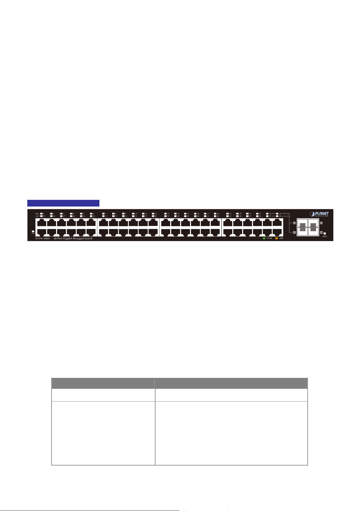
User’s Manual of WGSW-48000
2. INSTALLATION
This section describes the hardware features and installation of the Managed Switch on the desktop or rack mount. For easier
management and control of the Managed Switch, familiarize yourself with its display indicators, and ports. Front panel
illustrations in this chapter display the unit LED indicators. Before connecting any network device to the Managed Switch, please
read this chapter completely.
2.1 Hardware Description
2.1.1 Switch Front Panel
The unit front panel provides a simple interface monitoring the switch. Figure 2-1 shows the front panel of the Managed
Switches.
WGSW-48000 Front Panel
Figure 2-1 WGSW-48000 front panel.
■ Gigabit TP interface
10/100/1000Base-T Copper, RJ-45 Twist-Pair: Up to 100 meters.
■ Gigabit SFP slots
1000Base-SX/LX mini-GBIC slot, SFP (Small Factor Pluggable) transceiver module: From 550 meters (Multi-mode fiber),
up to 10/30/50/70/120 kilometers (Single-mode fiber).
■ Reset button
At the left of front panel, the reset button is designed for reboot the Managed Switch without turn off and on the power. The
following is the summary table of Reset button functions:
Reset Button Pressed and Released Function
About 1~3 second Reboot the Managed Switch
Reset the Managed Switch to Factory Default configuration.
The Managed Switch will then reboot and load the default
settings as below:
Until the PWR LED lit off
。 Default Password: admin
。 Default IP address: 192.168.0.100
。 Subnet mask: 255.255.255.0
。 Default Gateway: 192.168.0.254
27
Page 28
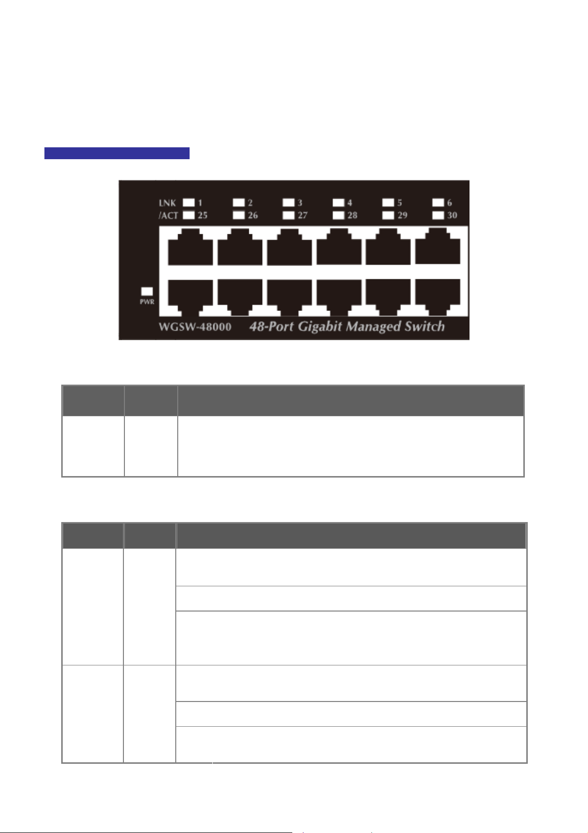
User’s Manual of WGSW-48000
2.1.2 LED Indications
The front panel LEDs indicates instant status of port links, data activity, system operation and system power, helps monitor and
troubleshoot when needed.
WGSW-48000 LED indication
■ System
LED Color Function
PWR Green
■ 10/100/1000Base-T interfaces
LED Color Function
1000
Green
LNK/ACT
Figure 2-3 WGSW-48000 LED panel
Lights to indicate that the Switch is powered on.
Blink to indicate the System is running under booting procedure.
Lights:
Blink:
Off:
To indicate the link through that port is successfully established with speed
1000Mbps
To indicate that the switch is actively sending or receiving data over that port.
If L10/100 NK/ACT LED light-> indicate that the port is operating at 10Mbps or
100Mbps
If LNK/ACT LED Off -> indicate that the port is link down
To indicate the link through that port is successfully established with speed
10Mbps or 100Mbps
To indicate that the switch is actively sending or receiving data over that port.
If 1000 LNK/ACT LED light-> indicate that the port is operating at 1000Mbps
If 1000 LNK/ACT LED Off -> indicate that the port is link down
10/100
LNK/ACT
Orange
Lights:
Blink:
Off:
28
Page 29

■ 1000Base-SX/LX SFP interfaces (Shared Port-23, Port-24, Port-47 and Port-48)
LED Color Function
User’s Manual of WGSW-48000
Lights:
1000
Green
LNK
Off:
To indicate the link through that SFP port is successfully established with
speed 1000Mbps
To indicate that the SFP port is link down
2.1.3 Switch Rear Panel
The rear panel of the Managed Switch indicates an AC inlet power socket, which accept input power from 100 to 240V AC,
50-60Hz. Figure 2-5 shows the rear panel of these Managed Switch.
WGSW-48000 Rear Panel
Figure 2-5 Rear panel of WGSW-48000
■ Console Port
The console port is a DB9, RS-232 male seria port connector. It is an interface for connecting a terminal directly. Through
the console port, it provides rich diagnostic information includes IP Address setting, factory reset, port management, link
status and system setting. Users can use the attached RS-232 cable in the package and connect to the console port on the
device. After the connection, users an run any terminal emulation program (Hyper Terminal, ProComm Plus, Telix, Winterm
and so on) to enter the statup screen of the device.
■ AC Power Receptacle
For compatibility with electric service in most areas of the world, the Managed Switch’s power supply automatically adjusts
to line power in the range 100-240VAC and 50/60 Hz.
Plug the female end of the power cord firmly into the receptalbe on the rear panel of the Managed Switch. Plug the other
end of the power cord into an electric service outlet then the power will be ready.
The device is a power-required device, it means, it will not work till it is powered. If your networks should
active all the time, please consider using UPS (Uninterrupted Power Supply) for your device. It will
Power Notice:
prevent you from network data loss or network downtime.
In some area, installing a surge suppression device may also help to protect your Managed Switch from
being damaged by unregulated surge or current to the Switch or the power adapter.
29
Page 30
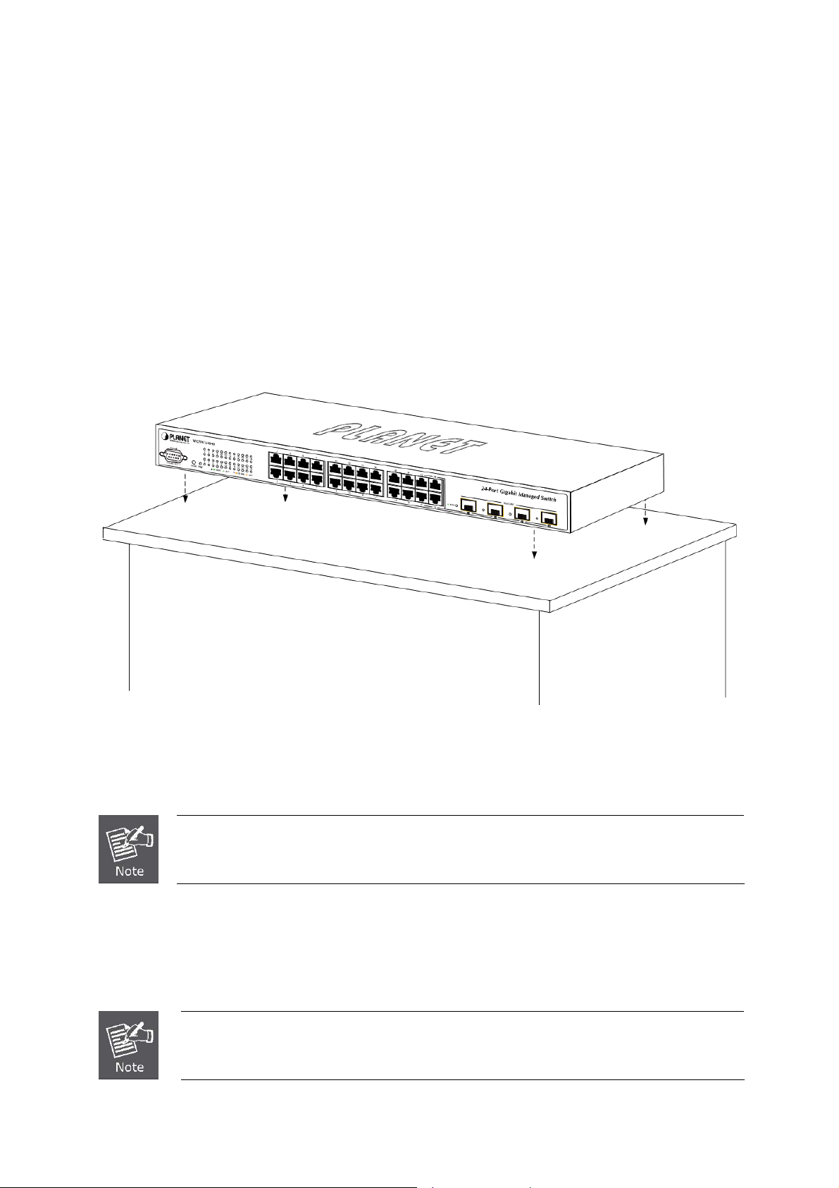
User’s Manual of WGSW-48000
2.2 Install the Switch
This section describes how to install your Managed Switch and make connections to the Managed Switch. Please read the
following topics and perform the procedures in the order being presented. To install your Managed Switch on a desktop or shelf,
simply complete the following steps.
2.2.1 Desktop Installation
To install the Managed Switch on desktop or shelf, please follows these steps:
Step1: Attach the rubber feet to the recessed areas on the bottom of the Managed Switch.
Step2: Place the Managed Switch on the desktop or the shelf near an AC power source, as shown in Figure 2-10.
Figure 2-10 Place the Managed Switch on the desktop
Step3: Keep enough ventilation space between the Managed Switch and the surrounding objects.
When choosing a location, please keep in mind the environmental restrictions discussed in Chapter
1, Section 4, and Specification.
Step4: Connect the Managed Switch to network devices.
Connect one end of a standard network cable to the 10/100/1000 RJ-45 ports on the front of the Managed Switch
Connect the other end of the cable to the network devices such as printer servers, workstations or routers…etc.
Connection to the Managed Switch requires UTP Category 5 network cabling with RJ-45 tips. For
more information, please see the Cabling Specification in Appendix A.
30
Page 31
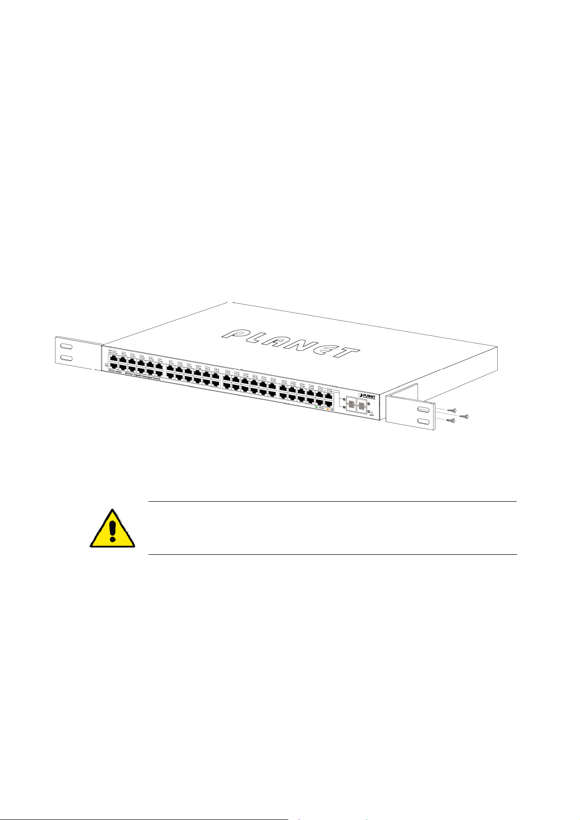
User’s Manual of WGSW-48000
Step5: Supply power to the Managed Switch.
Connect one end of the power cable to the Managed Switch.
Connect the power plug of the power cable to a standard wall outlet.
When the Managed Switch receives power, the Power LED should remain solid Green.
2.2.2 Rack Mounting
To install the Managed Switch in a 19-inch standard rack, please follows the instructions described below.
Step1: Place the Managed Switch on a hard flat surface, with the front panel positioned towards the front side.
Step2: Attach the rack-mount bracket to each side of the Managed Switch with supplied screws attached to the package.
Figure 2-11 shows how to attach brackets to one side of the Managed Switch.
Figure 2-11 Attach brackets to the Managed Switch.
You must use the screws supplied with the mounting brackets. Damage caused to the parts by
using incorrect screws would invalidate the warranty.
Step3: Secure the brackets tightly.
Step4: Follow the same steps to attach the second bracket to the opposite side.
Step5: After the brackets are attached to the Managed Switch, use suitable screws to securely attach the brackets to the rack,
as shown in Figure 2-12.
31
Page 32

User’s Manual of WGSW-48000
Figure 2-12 Mounting WGSW-48000 in a Rack
Step6: Proceeds with the steps 4 and steps 5 of session 2.2.1 Desktop Installation to connect the network cabling and supply
power to the Managed Switch.
2.2.3 Installing the SFP transceiver
The sections describe how to insert an SFP transceiver into an SFP slot.
The SFP transceivers are hot-pluggable and hot-swappable. You can plug-in and out the transceiver to/from any SFP port
without having to power down the Managed Switch. As the Figure 2-13 appears.
Figure 2-13 Plug-in the SFP transceiver
32
Page 33

User’s Manual of WGSW-48000
Approved PLANET SFP Transceivers
PLANET Managed Switch supports both Single mode and Multi-mode SFP transceiver. The following list of approved PLANET
SFP transceivers is correct at the time of publication:
■ MGB-SX SFP (1000BASE-SX SFP transceiver / Multi-mode / 850nm / 220m~550m)
■ MGB-LX SFP (1000BASE-LX SFP transceiver / Single mode / 1310nm / 10km)
■ MGB-L30 SFP (1000BASE-LX SFP transceiver / Single mode / 1310nm / 30km)
■ MGB-L50 SFP (1000BASE-LX SFP transceiver / Single mode / 1310nm / 50km)
■ MGB-LA10 SFP (1000BASE-LX SFP transceiver / WDM Single mode / TX: 1310nm, RX: 1550nm/ 10km)
■ MGB-LB10 SFP (1000BASE-LX SFP transceiver / WDM Single mode / TX: 1550nm, RX: 1310nm / 10km)
It recommends using PLANET SFPs on the Managed Switch. If you insert a SFP transceiver that is
not supported, the Managed Switch will not recognize it.
Before connect the other Managed Switches, workstation or Media Converter.
1. Make sure both side of the SFP transceiver are with the same media type, for example: 1000Base-SX to 1000Base-SX,
1000Bas-LX to 1000Base-LX.
2. Check the fiber-optic cable type match the SFP transceiver model.
¾ To connect to 1000Base-SX SFP transceiver, use the Multi-mode fiber cable- with one side must be male duplex LC
connector type.
¾ To connect to 1000Base-LX SFP transceiver, use the Single-mode fiber cable-with one side must be male duplex LC
connector type.
Connect the fiber cable
1. Attach the duplex LC connector on the network cable into the SFP transceiver.
2. Connect the other end of the cable to a device – switches with SFP installed, fiber NIC on a workstation or a Media
Converter..
3. Check the LNK/ACT LED of the SFP slot on the front of the Managed Switch. Ensure that the SFP transceiver is operating
correctly.
4. Check the Link mode of the SFP port if the link failed. Co works with some fiber-NICs or Media Converters, set the Link
mode to “1000 Force” is needed.
Remove the transceiver module
1. Make sure there is no network activity by consult or check with the network administrator. Or through the management
interface of the switch/converter (if available) to disable the port in advance.
2. Remove the Fiber Optic Cable gently.
3. Turn the handle of the MGB module to horizontal.
4. Pull out the module gently through the handle.
33
Page 34

User’s Manual of WGSW-48000
Figure 2-14 Pull out the SFP transceiver
Never pull out the module without pull the handle or the push bolts on the module. Direct pull
out the module with violent could damage the module and SFP module slot of the Managed
Switch.
34
Page 35

User’s Manual of WGSW-48000
3. SWITCH MANAGEMENT
This chapter explains the methods that you can use to configure management access to the Managed Switch. It describes the
types of management applications and the communication and management protocols that deliver data between your
management device (work-station or personal computer) and the system. It also contains information about port connection
options.
This chapter covers the following topics:
Requirements
Management Access Overview
Administration Console Access
Web Management Access
SNMP Access
Standards, Protocols, and Related Reading
3.1 Requirements
Workstations of subscribers running Windows 98/ME, NT4.0, 2000/XP, MAC OS9 or later, Linux, UNIX or other
platform compatible with TCP/IP protocols.
Workstation installed with Ethernet NIC (Network Interface Card)
Serial Port connect (Terminal)
• Above PC with COM Port (DB-9 / RS-232) or USB-to-RS-232 converter
Ethernet Port connect
• Network cables - Use standard network (UTP) cables with RJ45 connectors.
Above Workstation installed with WEB Browser and JAVA runtime environment Plug-in
It is recommended to use Internet Explore 6.0 or above to access Managed Switch.
35
Page 36

User’s Manual of WGSW-48000
3.2 Management Access Overview
The Managed Switch gives you the flexibility to access and manage it using any or all of the following methods:
An administration console
Web browser interface
An external SNMP-based network management application
The administration console and Web browser interface support are embedded in the Managed Switch software and are
available for immediate use. Each of these management methods has their own advantages. Table 3-1 compares the three
management methods.
Method Advantages Disadvantages
Console
Web Browser
SNMP Agent
• No IP address or subnet needed
• Text-based
• Telnet functionality and HyperTerminal
built into Windows
95/98/NT/2000/ME/XP operating
systems
• Secure
• Ideal for configuring the switch remotely
• Compatible with all popular browsers
• Can be accessed from any location
• Most visually appealing
• Communicates with switch functions at
the MIB level
• Based on open standards
• Must be near switch or use dial-up connection
• Not convenient for remote users
• Modem connection may prove to be unreliable
or slow
• Security can be compromised (hackers need
only know the IP address and subnet mask)
• May encounter lag times on poor connections
• Requires SNMP manager software
• Least visually appealing of all three methods
• Some settings require calculations
• Security can be compromised (hackers need
only know the community name)
Table 3-1 Management Methods Comparison
3.3 Administration Console
The administration console is an internal, character-oriented, and command line user interface for performing system
administration such as displaying statistics or changing option settings. Using this method, you can view the administration
console from a terminal, personal computer, Apple Macintosh, or workstation connected to the switch's console (serial) port.
There are two ways to use this management method: via direct access or modem port access. The following sections describe
these methods. For more information about using the console, refer to Chapter 5 Command Line Interface Console
Management.
36
Page 37

User’s Manual of WGSW-48000
Figure 3-1 Console management
Direct Access
Direct access to the administration console is achieved by directly connecting a terminal or a PC equipped with a
terminal-emulation program (such as HyperTerminal) to the Managed Switch console (serial) port.
When using this management method, a straight DB9 RS-232 cable is required to connect the switch to the PC. After
making this connection, configure the terminal-emulation program to use the following parameters:
The default parameters are:
38400 bps
8 data bits
No parity
1 stop bit
Figure 3-2 Terminal parameter settings
37
Page 38

User’s Manual of WGSW-48000
You can change these settings, if desired, after you log on. This management method is often preferred because you can
remain connected and monitor the system during system reboots. Also, certain error messages are sent to the serial port,
regardless of the interface through which the associated action was initiated. A Macintosh or PC attachment can use any
terminal-emulation program for connecting to the terminal serial port. A workstation attachment under UNIX can use an emulator
such as TIP.
3.4 Web Management
The Managed Switch offers management features that allow users to manage the Managed Switch from anywhere on the
network through a standard browser such as Microsoft Internet Explorer. After you set up your IP address for the switch, you can
access the Managed Switch's Web interface applications directly in your Web browser by entering the IP address of the
Managed Switch.
Figure 3-3 Web management
You can then use your Web browser to list and manage the Managed Switch configuration parameters from one central location,
just as if you were directly connected to the Managed Switch's console port. Web Management requires either Microsoft
Internet Explorer 6.0 or later, Safari or Mozilla Firefox 1.5 or later.
38
Page 39

User’s Manual of WGSW-48000
Figure 3-4 Web main screen of Managed Switch
3.5 SNMP-Based Network Management
You can use an external SNMP-based application to configure and manage the Managed Switch, such as SNMPc Network
Manager, HP Openview Network Node Management (NNM) or What’s Up Gold. This management method requires the SNMP
agent on the switch and the SNMP Network Management Station to use the same community string. This management
method, in fact, uses two community strings: the get community string and the set community string. If the SNMP Net-work
management Station only knows the set community string, it can read and write to the MIBs. However, if it only knows the get
community string, it can only read MIBs. The default gets and sets community strings for the Managed Switch are public.
Figure 3-4 SNMP management
39
Page 40

User’s Manual of WGSW-48000
3.6 Protocols
The Managed Switch supports the following protocols:
Virtual terminal protocols, such as Telnet
Simple Network Management Protocol (SNMP)
3.6.1 Virtual Terminal Protocols
A virtual terminal protocol is a software program, such as Telne t, that allows you to establish a management session from a
Macintosh, a PC, or a UNIX workstation. Because Telnet runs over TCP/IP, you must have at least one IP address configured on
the Managed Switch before you can establish access to it with a virtual terminal protocol.
Terminal emulation differs from a virtual terminal protocol in that you must connect a terminal directly
to the console (serial) port.
To access the Managed Switch through a Telnet session:
1. Be Sure of the Managed Switch is configured with an IP address and the Managed Switch is reachable from a PC.
2. Start the Telnet program on a PC and connect to the Managed Switch.
The management interface is exactly the same with RS-232 console management.
3.6.2 SNMP Protocol
Simple Network Management Protocol (SNMP) is the standard management protocol for multi-vendor IP networks. SNMP
supports transaction-based queries that allow the protocol to format messages and to transmit information between reporting
devices and data-collection programs. SNMP runs on top of the User Datagram Protocol (UDP), offering a connectionless-mode
service.
3.6.3 Management Architecture
All of the management application modules use the same Messaging Application Programming Interface (MAPI). By unifying
management methods with a single MAPI, configuration parameters set using one method (console port, for example) are
immediately displayable by the other management methods (for example, SNMP agent of Web browser).
The management architecture of the switch adheres to the IEEE open standard. This compliance assures customers that the
Managed Switch is compatible with, and will interoperate with other solutions that adhere to the same open standard.
40
Page 41

User’s Manual of WGSW-48000
4. WEB CONFIGURATION
This section introduces the configuration and functions of the Web-Based management.
About Web-based Management
The Managed Switch offers management features that allow users to manage the Managed Switch from anywhere on the
network through a standard browser such as Microsoft Internet Explorer.
The Web-Based Management supports Internet Explorer 6.0. It is based on Java Applets with an aim to reduce network
bandwidth consumption, enhance access speed and present an easy viewing screen.
By default, IE6.0 or later version does not allow Java Applets to open sockets. The user has to
explicitly modify the browser setting to enable Java Applets to use network ports.
The Managed Switch can be configured through an Ethernet connection, make sure the manager PC must be set on same the
IP subnet address with the Managed Switch.
For example, the default IP address of the WGSW Managed Switch is 192.168.0.100, then the manager PC should be set at
192.168.0.x (where x is a number between 1 and 254, except 100), and the default subnet mask is 255.255.255.0.
If you have changed the default IP address of the Managed Switch to 192.168.1.1 with subnet mask 255.255.255.0 via console,
then the manager PC should be set at 192.168.1.x (where x is a number between 2 and 254) to do the relative configuration on
manager PC.
WGSW Managed Switch
PC/Workstation
With
IE Browser
IP Address:
192.168.0.100
RJ-45/UTP Cable
IP Address:
192.168.0.x
Figure 4-1-1 Web Management
41
Page 42

User’s Manual of WGSW-48000
Logging on the switch
1. Use Internet Explorer 6.0 or above Web browser. Enter the factory-default IP address to access the Web interface. The
factory-default IP Address as following:
http://192.168.0.100
2. When the following login screen appears, please enter the default username "admin" with password “admin” (or the
username/password you have changed via console) to login the main screen of Managed Switch. The login screen in
Figure 4-1-2 appears.
Figure 4-1-2 Login screen
Default User name: admin
Default Password: admin
After entering the username and password, the main screen appears as Figure 4-1-3.
42
Page 43

User’s Manual of WGSW-48000
Figure 4-1-3 Default main page
Now, you can use the Web management interface to continue the switch management or manage the Managed Switch by Web
interface. The Switch Menu on the left of the web page let you access all the commands and statistics the Managed Switch
provides.
1. It is recommended to use Internet Explore 6.0 or above to access Managed Switch.
2. The changed IP address take effect immediately after click on the Save button, you need to
use the new IP address to access the Web interface.
3. For security reason, please change and memorize the new password after this first setup.
4. Only accept command in lowercase letter under web interface.
43
Page 44

User’s Manual of WGSW-48000
4.1 Main WEB PAGE
The WGSW Managed Switch provides a Web-based browser interface for configuring and managing it. This interface allows
you to access the Managed Switch using the Web browser of your choice. This chapter describes how to use the Managed
Switch’s Web browser interface to configure and manage it.
Main Functions Menu
Copper Port Link Status
SFP Port Link Status
Main Screen
Figure 4-1-4 Main Page
Help Button
Panel Display
The web agent displays an image of the Managed Switch’s ports. The Mode can be set to display different information for the
ports, including Link up or Link down. Clicking on the image of a port opens the Port Statistics page.
The port states are illustrated as follows:
State Disabled Down Link
RJ-45 Ports
SFP Ports
607H 608H 609H
Main Menu
Using the onboard web agent, you can define system parameters, manage and control the Managed Switch, and all its ports, or
monitor network conditions. Via the Web-Management, the administrator can setup the Managed Switch by select the functions
those listed in the Main Function. The screen in Figure 4-1-5 appears.
44
Page 45

User’s Manual of WGSW-48000
Figure 4-1-5 WGSW Managed Switch Main Funcrions Menu
45
Page 46

User’s Manual of WGSW-48000
4.2 System
Use the System menu items to display and configure basic administrative details of the Managed Switch. Under System the
following topics are provided to configure and view the system information: This section has the following items:
4.2.1 System Information
The System Info page provides information for the current device information. System Info page helps a switch administrator to
identify the hardware MAC address, software version and system uptime.
The page includes the following fields:
Object Description
• Device name
• Hardware Version
• Firmware Version
• Build Date
• MAC Address
• System Name
• System Location
• System Contact
Figure 4-2-1 System Information Screenshot
Displays the switch model name.
Displays the hardware version number.
Displays the switch firmware version.
Displays the firmware built date.
Displays the MAC address of the switch.
Displays the user-defined system name.
Displays the user-defined system location.
Displays the user-defined system contact person.
46
Page 47
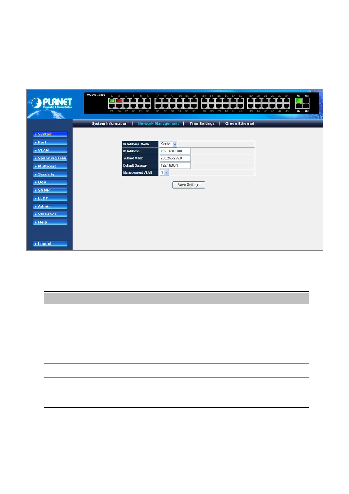
User’s Manual of WGSW-48000
4.2.2 Network Management
The Network Managment includes the IP Address, Subnet Mask and Gateway. The Configured column is used to view or
change the IP configuration.Fill up the IP Address, Subnet Mask and Gateway for the device. The screen in Figure 4-2-2
appears.
The page includes the following fields:
Object Description
• IP Address Mode
• IP Address
• Subnet Mask
• Default Gateway
• Management VLAN
Figure 4-2-2 Network Management screenshot
Retrieves the IP address using DHCP or Static.
The possible field values are DHCP that retrieves the IP addresses using DHCP
client; Static indicates IP address is statically assigned. If Static was selected, the
IP Address, Subnet Mask and Default Gateway fields are available.
Defines the IP address of the system.
Defines the subnet mask of the system.
Defines the default gateway IP address of the system.
Indicates the VLAN group that system belongs to.
47
Page 48

User’s Manual of WGSW-48000
4.2.3 Time Setting
In the System sub-function menu, you can see the Time Setting, by which you can configure the time settings for the Managed
Switch. You can specify SNTP Servers and set GMT Timezone. The SNTP Configuration screen in Figure 4-2-3 appears.
The page includes the following fields:
Object Description
• Daylight Saving
• Time Zone
• Use Local Time
Figure 4-2-3 Time Settings
Indicates the Daylight Savings Time (DST) on the device based on the devices
location. When daylight saving is enabled, one hour will be added to time zone
offset value. (Only for SNTP)
Specifies the difference between Greenwich Mean Time (GMT) and local time.
For example, the Time Zone Offset for Paris is GMT +1, while the local time in
New York is GMT -5. (Only for SNTP)
M: Month - Sets the month.
D: Day - Sets the day.
Y: Year - Sets the year.
H: Hours - Sets the hours.
M: Minutes - Sets the minutes.
S: Seconds - Sets the seconds.
Use Browser Time - The device system time is configured by your
Desktop/Laptop's time setting.
48
Page 49

User’s Manual of WGSW-48000
• Use SNTP Server
The device supports the Simple Network Time Protocol (SNTP). SNTP assures
accurate network device clock time synchronization up to the millisecond. Time
synchronization is performed by a network SNTP server. The device operates
only as an SNTP client, and cannot provide time services to other systems. The
device can poll the following server types for the server time:
Server IP Address - Sets the SNTP server's IP address.
Update Time Now - Synchronizes current device time with the SNTP server
right away.
Polling Interval - Sets the interval at which SNTP client polls for time.
4.2.4 Green Ethernet
This page is used to enable/disable green Ethernet function. Enable green Ethernet mode will reduce system power
consumption when the link is not present.
Figure 4-2-4 Green Ethernet screenshot
Enable mode will reduce chip power when the signal from the copper link partner is not present.
49
Page 50

User’s Manual of WGSW-48000
4.3 Port Management
Use the Port Menu to display or configure the Managed Switch's ports. This section has the following items:
- Port Configuration
- LACP Property
- LAG Group
4.3.1 Port Configuration
This page displays current port configurations. Ports can also be configured here.
The port settings relate to the currently selected stack unit, as reflected by the page header.
Figure 4-3-1 Port Configuration screenshot
The page includes the following fields:
Object Description
• Port Number
• Admin Mode
• Auto Negotiation
Indicates the port numbers in the system.
Click on the port index will enter port configuration page.
Configure the administrative mode of the port. Sets to Disable will force the port
to link down status.
Configure the port auto-negotiation capability. When auto-negotiation is enabled,
the port negotiates with the link partner and works out speed and duplex
operation. When auto-negotiation is disabled, port speed and duplex operation is
programmable by the user.
50
Page 51

User’s Manual of WGSW-48000
• Speed Duplex
• Flow Control
• LAG Group
• Link Status
Indicates the speed and duplex mode if the port is linkup.
Indicates the state of flow control if the port is linkup.
Indicates the LAG group if the port is a LAG port.
Displays the link status of the port.
Figure 4-3-2 Port Detail Configuration
51
Page 52

User’s Manual of WGSW-48000
4.3.2 LACP Property
Link Aggregation Control Protocol (LACP) is part of an IEEE specification (802.3ad) that allows several physical ports to be
bundled together to form a single logical channel. Link Aggregation allows one or more links to be aggregated together to form a
Link Aggregation Group, such that a MAC Client can treat the Link Aggregation Group as if it were a single link. Link aggregation
can be used on 10Mbps, 100Mbps, or 1000Mbps ethernet full duplex ports. Example: A network administrator could combine a
group of four 1000Mbps ports into a logical link that will function as a single 4000Mbps port (The actual throughput however will
be less than the sum total of the links).
Figure 4-3-3Link Aggregation
The Link Aggregation Control Protocol (LACP) provides a standardized means for exchanging information between Partner
Systems that require high speed redundant links. Link aggregation lets you group up to eight consecutive ports into a single
dedicated connection. This feature can expand bandwidth to a device on the network. LACP operation requires full-duplex mode,
more detail information refer to the IEEE 802.3ad standard.
Port link aggregations can be used to increase the bandwidth of a network connection or to ensure fault recovery. Link
aggregation lets you group up to 4 consecutive ports into a single dedicated connection between any two the Switch or other
Layer 2 switches. However, before making any physical connections between devices, use the Link aggregation Configuration
menu to specify the link aggregation on the devices at both ends. When using a port link aggregation, note that:
52
Page 53

User’s Manual of WGSW-48000
• The ports used in a link aggregation must all be of the same media type (RJ-45, 100 Mbps fiber).
• The ports that can be assigned to the same link aggregation have certain other restrictions (see below).
• Ports can only be assigned to one link aggregation.
• The ports at both ends of a connection must be configured as link aggregation ports.
• None of the ports in a link aggregation can be configured as a mirror source port or a mirror target port.
• All of the ports in a link aggregation have to be treated as a whole when moved from/to, added or deleted from a VLAN.
• The Spanning Tree Protocol will treat all the ports in a link aggregation as a whole.
• Enable the link aggregation prior to connecting any cable between the switches to avoid creating a data loop.
• Disconnect all link aggregation port cables or disable the link aggregation ports before removing a port link aggregation to
avoid creating a data loop.
It allows a maximum of 8 ports to be aggregated at the same time. The Managed Switch support Gigabit Ethernet ports (up to
14groups). If the group is defined as a LACP static link aggregationing group, then any extra ports selected are placed in a
standby mode for redundancy if one of the other ports fails. If the group is defined as a local static link aggregationing group,
then the number of ports must be the same as the group member ports.
The aggregation code ensures that frames belonging to the same frame flow (for example, a TCP connection) are always
forwarded on the same link aggregation member port. Reording of frames within a flow is therefore not possible. The
aggregation code is based on the following information:
• Source MAC
• Destination MAC
• Source and destination IPv4 address.
• Source and destination TCP/UDP ports for IPv4 packets
Normally, all 5 contributions to the aggregation code should be enabled to obtain the best traffic distribution among the link
aggregation member ports. Each link aggregation may consist of up to 8 member ports. Any quantity of link aggregation s may
be configured for the device (only limited by the quantity of ports on the device.) To configure a proper traffic distribution, the
ports within a link aggregation must use the same link speed.
Link Aggregation Port Configuration
Link Aggregation Control Protocol (LACP) - LACP LAG negotiate Aggregated Port links with other LACP ports located on a
different device. LACP allows switches connected to each other to discover automatically whether any ports are member of the
same LAG.
This page allows the user to inspect the current LACP port configurations, and possibly change them as well. The LACP port
settings relate to the currently selected stack unit, as reflected by the page header. The LACP Port Configuration screen in
Figure 4-3-4 appears.
53
Page 54

User’s Manual of WGSW-48000
The page includes the following fields:
Object Description
• LACP System Priority
• Port Number
• Priority
• Admin Key
Figure 4-3-4 LACP Property
Specifies the actor device's link aggregation priority relative to the devices at the
other ends of the links on which link aggregation is enabled. A higher value
indicates a lower priority.
Display the port number. Click on the index number will enter port LACP
properties configuration screen.
Indicates actor port priority. The port priority determines the active and standby
links. When a group of ports is negotiating with a group of ports on another
device to establish a trunk group, the port with the highest priority becomes the
default active port. The other ports (with lower priorities) become standby ports in
the trunk group.
Indicates actor administration key for the port. The LACP administration key must
be set to the same value for ports that belong to the same LAG.
• LAG Group
• Status
• LACP Port Priority
Indicates the LAG group ID if the port is the member of this LAG group.
Summarizes the current LACP status for this port.
Specifies actor port priority. The port priority determines the active and standby
links. When a group of ports is negotiating with a group of ports on another
device to establish a LAG group, the port with the highest priority becomes the
default active port. The other ports (with lower priorities) become standby ports in
the LAG group. You can specify a priority from 0 to 65535.
54
Page 55

User’s Manual of WGSW-48000
All information listed here is for reference only. Please refer to IEEE 802.3ad for details.
4.3.3 LAG Group
Link Aggregated Groups optimize port usage by linking a group of ports together to form a single aggregated group. Link
aggregated groups multiply the bandwidth between the devices, increase port flexibility, and provide link redundancy.
The page includes the following fields:
Object Description
• LAG Group
• Port Member
• Link Status
• Speed /Duplex
Figure 4-3-4 LAG Group
Displays the LAG groups.
Displays the ports that are members of this LAG.
Displays the link status.
Display the connection speed and duplex.
55
Page 56

User’s Manual of WGSW-48000
4.4 VLAN
4.4.1 VLAN Overview
A Virtual Local Area Network (VLAN) is a network topology configured according to a logical scheme rather than the physical
layout. VLAN can be used to combine any collection of LAN segments into an autonomous user group that appears as a single
LAN. VLAN also logically segment the network into different broadcast domains so that packets are forwarded only between
ports within the VLAN. Typically, a VLAN corresponds to a particular subnet, although not necessarily.
VLAN can enhance performance by conserving bandwidth, and improve security by limiting traffic to specific domains.
A VLAN is a collection of end nodes grouped by logic instead of physical location. End nodes that frequently communicate with
each other are assigned to the same VLAN, regardless of where they are physically on the network. Logically, a VLAN can be
equated to a broadcast domain, because broadcast packets are forwarded to only members of the VLAN on which the
broadcast was initiated.
1. No matter what basis is used to uniquely identify end nodes and assign these nodes VLAN
membership, packets cannot cross VLAN without a network device performing a routing
function between the VLAN.
2. The Managed Switch supports IEEE 802.1Q VLAN. The port untagging function can be used
to remove the 802.1 tag from packet headers to maintain compatibility with devices that are
tag-unaware.
3. The Managed Switch's default is to assign all ports to a single 802.1Q VLAN named
DEFAULT_VLAN. As new VLAN is created, the member ports assigned to the new VLAN will
be removed from the DEFAULT_ VLAN port member list. The DEFAULT_VLAN has a VID = 1.
This section has the following items:
IEEE 802.1Q VLAN
Enable IEEE 802.1Q Tag based VLAN group
4.4.2 IEEE 802.1Q VLAN
In large networks, routers are used to isolate broadcast traffic for each subnet into separate domains. This Managed Switch
provides a similar service at Layer 2 by using VLANs to organize any group of network nodes into separate broadcast domains.
VLANs confine broadcast traffic to the originating group, and can eliminate broadcast storms in large networks. This also
provides a more secure and cleaner network environment.
An IEEE 802.1Q VLAN is a group of ports that can be located anywhere in the network, but communicate as though they belong
to the same physical segment.
VLANs help to simplify network management by allowing you to move devices to a new VLAN without having to change any
56
Page 57

User’s Manual of WGSW-48000
physical connections. VLANs can be easily organized to reflect departmental groups (such as Marketing or R&D), usage groups
(such as e-mail), or multicast groups (used for multimedia applications such as videoconferencing).
VLANs provide greater network efficiency by reducing broadcast traffic, and allow you to make network changes without having
to update IP addresses or IP subnets. VLANs inherently provide a high level of network security since traffic must pass through
a configured Layer 3 link to reach a different VLAN.
This Managed Switch supports the following VLAN features:
Up to 255 VLANs based on the IEEE 802.1Q standard
Distributed VLAN learning across multiple switches using explicit or implicit tagging and GVRP protocol
Port overlapping, allowing a port to participate in multiple VLANs
End stations can belong to multiple VLANs
Passing traffic between VLAN-aware and VLAN-unaware devices
Priority tagging
1. The Managed Switch allows 4k user-manageable VLANs.
■ IEEE 802.1Q Standard
IEEE 802.1Q (tagged) VLAN are implemented on the Switch. 802.1Q VLAN require tagging, which enables them to span the
entire network (assuming all switches on the network are IEEE 802.1Q-compliant).
VLAN allow a network to be segmented in order to reduce the size of broadcast domains. All packets entering a VLAN will only
be forwarded to the stations (over IEEE 802.1Q enabled switches) that are members of that VLAN, and this includes broadcast,
multicast and unicast packets from unknown sources.
VLAN can also provide a level of security to your network. IEEE 802.1Q VLAN will only deliver packets between stations that are
members of the VLAN. Any port can be configured as either tagging or untagging. The untagging feature of IEEE 802.1Q VLAN
allows VLAN to work with legacy switches that don't recognize VLAN tags in packet headers. The tagging feature allows VLAN
to span multiple 802.1Q-compliant switches through a single physical connection and allows Spanning Tree to be enabled on all
ports and work normally.
Any port can be configured as either tagging or untagging. The untagging feature of IEEE 802.1Q VLAN allow VLAN to work
with legacy switches that don’t recognize VLAN tags in packet headers. The tagging feature allows VLAN to span multiple
802.1Q-compliant switches through a single physical connection and allows Spanning Tree to be enabled on all ports and work
normally.
Some relevant terms:
- Tagging - The act of putting 802.1Q VLAN information into the header of a packet.
- Untagging - The act of stripping 802.1Q VLAN information out of the packet header.
57
Page 58

User’s Manual of WGSW-48000
■ 802.1Q VLAN Tags
The figure below shows the 802.1Q VLAN tag. There are four additional octets inserted after the source MAC address. Their
presence is indicated by a value of 0x8100 in the Ether Type field. When a packet's Ether Type field is equal to 0x8100, the
packet carries the IEEE 802.1Q/802.1p tag. The tag is contained in the following two octets and consists of 3 bits of user priority,
1 bit of Canonical Format Identifier (CFI - used for encapsulating Token Ring packets so they can be carried across Ethernet
backbones), and 12 bits of VLAN ID (VID). The 3 bits of user priority are used by 802.1p. The VID is the VLAN identifier and is
used by the 802.1Q standard. Because the VID is 12 bits long, 4094 unique VLAN can be identified.
The tag is inserted into the packet header making the entire packet longer by 4 octets. All of the information originally contained
in the packet is retained.
802.1Q Tag
User Priority CFI
VLAN ID (VID)
3 bits 1 bits 12 bits
TPID (Tag Protocol Identifier) TCI (Tag Control Information)
2 bytes 2 bytes
Preamble Destination
Address
Source
Address
VLAN TAG
Ethernet
Type
Data FCS
6 bytes 6 bytes 4 bytes 2 bytes 46-1517 bytes 4 bytes
The Ether Type and VLAN ID are inserted after the MAC source address, but before the original Ether Type/Length or Logical
Link Control. Because the packet is now a bit longer than it was originally, the Cyclic Redundancy Check (CRC) must be
recalculated.
Adding an IEEE802.1Q Tag
Dest. Addr. Src. Addr. Length/E. type Data Old CRC
Dest. Addr. Src. Addr.
E. type Tag
Length/E. type Data New CRC
Priority CFI VLAN ID
58
Original Ethernet
New Tagged Packet
Page 59

User’s Manual of WGSW-48000
■ Port VLAN ID
Packets that are tagged (are carrying the 802.1Q VID information) can be transmitted from one 802.1Q compliant network
device to another with the VLAN information intact. This allows 802.1Q VLAN to span network devices (and indeed, the entire
network – if all network devices are 802.1Q compliant).
Every physical port on a switch has a PVID. 802.1Q ports are also assigned a PVID, for use within the switch. If no VLAN are
defined on the switch, all ports are then assigned to a default VLAN with a PVID equal to 1. Untagged packets are assigned the
PVID of the port on which they were received. Forwarding decisions are based upon this PVID, in so far as VLAN are concerned.
Tagged packets are forwarded according to the VID contained within the tag. Tagged packets are also assigned a PVID, but the
PVID is not used to make packet forwarding decisions, the VID is.
Tag-aware switches must keep a table to relate PVID within the switch to VID on the network. The switch will compare the VID of
a packet to be transmitted to the VID of the port that is to transmit the packet. If the two VID are different the switch will drop the
packet. Because of the existence of the PVID for untagged packets and the VID for tagged packets, tag-aware and tag-unaware
network devices can coexist on the same network.
A switch port can have only one PVID, but can have as many VID as the switch has memory in its VLAN table to store them.
Because some devices on a network may be tag-unaware, a decision must be made at each port on a tag-aware device before
packets are transmitted – should the packet to be transmitted have a tag or not? If the transmitting port is connected to a
tag-unaware device, the packet should be untagged. If the transmitting port is connected to a tag-aware device, the packet
should be tagged.
■ Default VLANs
The Switch initially configures one VLAN, VID = 1, called "default." The factory default setting assigns all ports on the Switch to
the "default". As new VLAN are configured in Port-based mode, their respective member ports are removed from the "default."
■ Assigning Ports to VLANs
Before enabling VLANs for the switch, you must first assign each port to the VLAN group(s) in which it will participate. By default
all ports are assigned to VLAN 1 as untagged ports. Add a port as a tagged port if you want it to carry traffic for one or more
VLANs, and any intermediate network devices or the host at the other end of the connection supports VLANs. Then assign ports
on the other VLAN-aware network devices along the path that will carry this traffic to the same VLAN(s), either manually or
dynamically using GVRP. However, if you want a port on this switch to participate in one or more VLANs, but none of the
intermediate network devices nor the host at the other end of the connection supports VLANs, then you should add this port to
the VLAN as an untagged port.
VLAN-tagged frames can pass through VLAN-aware or VLAN-unaware network interconnection
devices, but the VLAN tags should be stripped off before passing it on to any end-node host that
does not support VLAN tagging.
59
Page 60

User’s Manual of WGSW-48000
■ VLAN Classification
When the switch receives a frame, it classifies the frame in one of two ways. If the frame is untagged, the switch assigns the
frame to an associated VLAN (based on the default VLAN ID of the receiving port). But if the frame is tagged, the switch uses
the tagged VLAN ID to identify the port broadcast domain of the frame.
■ Port Overlapping
Port overlapping can be used to allow access to commonly shared network resources among different VLAN groups, such as
file servers or printers. Note that if you implement VLANs which do not overlap, but still need to communicate, you can connect
them by enabled routing on this switch.
■ Untagged VLANs
Untagged (or static) VLANs are typically used to reduce broadcast traffic and to increase security. A group of network users
assigned to a VLAN form a broadcast domain that is separate from other VLANs configured on the switch. Packets are
forwarded only between ports that are designated for the same VLAN. Untagged VLANs can be used to manually isolate user
groups or subnets. However, you should use IEEE 802.3 tagged VLANs with GVRP whenever possible to fully automate VLAN
registration.
3. Automatic VLAN Registration
GVRP (GARP VLAN Registration Protocol) defines a system whereby the switch can automatically learn the VLANs to which
each end station should be assigned. If an end station (or its network adapter) supports the IEEE 802.1Q VLAN protocol, it can
be configured to broadcast a message to your network indicating the VLAN groups it wants to join. When this switch receives
these messages, it will automatically place the receiving port in the specified VLANs, and then forward the message to all other
ports. When the message arrives at another switch that supports GVRP, it will also place the receiving port in the specified
VLANs, and pass the message on to all other ports. VLAN requirements are propagated in this way throughout the network.
This allows GVRP-compliant devices to be automatically configured for VLAN groups based solely on endstation requests.
To implement GVRP in a network, first add the host devices to the required VLANs (using the operating system or other
application software), so that these VLANs can be propagated onto the network. For both the edge switches attached directly to
these hosts, and core switches in the network, enable GVRP on the links between these devices. You should also determine
security boundaries in the network and disable GVRP on the boundary ports to prevent advertisements from being propagated,
or forbid those ports from joining restricted VLANs.
If you have host devices that do not support GVRP, you should configure static or untagged VLANs
for the switch ports connected to these devices (as described in “Adding Static Members to VLANs
(VLAN Index)”). But you can still enable GVRP on these edge switches, as well as on the core
switches in the network.
60
Page 61

User’s Manual of WGSW-48000
4.4.3 Create VLAN
The Create VLAN screen provides information and global parameters for configuring and working with VLANs.
The page includes the following fields:
Object Description
• Single VLAN
• Multiple VLAN
• VLAN Group Table
• Tagged
• Untagged
Figure 4-4-1 Create VLAN screenshot
Indicates the ID number of the VLAN being configured. Up to 256 VLANs can be
created. This field is used to create one VLAN group at a time.
Specifies a range of VLANs being configured. It allows multiple VLAN groups
being created at a time.
Displays all VLAN groups with their member ports . There are two color symbols
for each VLAN group member port, that is Tagged and Untagged
Indicates that this port is a member of the VLAN. When the packet leaves the
member port, the VLAN tag is kept.
Indicates that this port is a member of the VLAN. When the packet leaves the
member port, the VLAN tag is removed.
61
Page 62

User’s Manual of WGSW-48000
4.4.4 VLAN Setting
The VLAN Setting screen contains fields for configuring ports to a VLAN. The port default VLAN ID (PVID) is configured on the
Create VLAN screen. All untagged packets arriving to the device are tagged by the ports PVID. The VLAN Settings screen
contains a Port Table for VLAN parameters for each port. Ports are assigned VLAN membership by selecting and configuring
the presented configuration options, you can refer to Figure 4-4-2.
Figure 4-4-2 VLAN Setting
Understand nomenclature of the Switch
■ IEEE 802.1Q Tagged and Untagged
Every port on an 802.1Q compliant switch can be configured as tagged or untagged.
• Tagged:
• Untagged:
Ports with tagging enabled will put the VID number, priority and other VLAN information into the
header of all packets that flow into those ports. If a packet has previously been tagged, the port
will not alter the packet, thus keeping the VLAN information intact. The VLAN information in the
tag can then be used by other 802.1Q compliant devices on the network to make
packet-forwarding decisions.
Ports with untagging enabled will strip the 802.1Q tag from all packets that flow into those
ports. If the packet doesn't have an 802.1Q VLAN tag, the port will not alter the packet. Thus,
all packets received by and forwarded by an untagging port will have no 802.1Q VLAN
information. (Remember that the PVID is only used internally within the Switch). Untagging is
used to send packets from an 802.1Q-compliant network device to a non-compliant network
device.
62
Page 63

User’s Manual of WGSW-48000
Frame Income
Frame Leave
Leave port is tagged Frame remains tagged Tag is inserted
Leave port is untagged Tag is removed Frame remain untagged
The page includes the following fields:
Object Description
• VLAN Group
• Excluded
• Untagged
• Tagged
Income Frame is tagged Income Frame is untagged
Indicates the VLAN for which the port membership is configured.
Excludes the Port/LAG from the VLAN.
Indicates that this Port/LAG is a member of the VLAN. When the packet leaves
the member Port/LAG, the VLAN tag is removed.
Indicates that this Port/LAG is a member of the VLAN. When the packet leaves
the member Port/LAG, the VLAN tag is kept.
The port must be a member of the same VLAN as the Port VLAN ID.
63
Page 64

User’s Manual of WGSW-48000
4.4.5 VLAN Port
This page is used for configuring the Managed Switch port VLAN. The VLAN per Port Configuration page contains fields for
managing ports that are part of a VLAN. The port default VLAN ID (PVID) is configured on the VLAN Port Configuration page.
All untagged packets arriving to the device are tagged by the ports PVID.
The page includes the following fields:
Object Description
• PVID
• Protected Port
• Drop Non 1Q Frame
• VLAN Ingress Filter
Figure 4-4-3 VLAN Port
The port default VLAN ID (PVID) is configured on the VLAN Port screen. All
untagged packets arrive to the device are tagged by the ports PVID.
When the ports specified as 'Protected Port', they can not forward traffic to each
other. Only the ports that are not specified as 'Protected Port' can forward traffic
to and from the protected ports respectively.
When enabled, any Non-1Q ingress frame will be dropped by this port.
Enable ingress filtering for a port by checking the box. This parameter affects
VLAN ingress processing. If ingress filtering is enabled and the ingress port is not
a member of the classified VLAN of the frame, the frame is discarded.
By default, ingress filtering is disabled (no checkmark).
64
Page 65

User’s Manual of WGSW-48000
4.4.6 GVRP
When Switch GVRP is enabled, you can modify the GVRP settings of multiple ports.
But if it's disabled, GVRP will be disabled on all ports.
Click the Modify hyperlink to modify the GVRP settings of multiple ports when Switch GVRP is enabled.
On the port GVRP modification page, you can enable/disable GVRP on the port you specified.
Figure 4-4-4 GVRP
The page contains the following fields:
• Enable GVRP
• Port
• GVRP Mode
• Join Period
• Leave Period
Enables and disables GVRP on the device
Displays the interface on which GVRP is enabled. Possible field values are:
Port - indicates the port number on which GVRP is enabled.
LAG - indicates the LAG number on which GVRP is enabled.
When the checkbox is checked, GVRP is enabled on the interface
The interval between transmitting requests/queries to participate in a VLAN group.
Range: 20-1000 centiseconds.
Default: 20 centiseconds
The interval a port waits before leaving a VLAN group. This time should be set to
more than twice the join time. This ensures that after a Leave or LeaveAll message
65
Page 66

User’s Manual of WGSW-48000
has been issued, the applicants can rejoin before the port actually leaves the group.
Range: 60-3000 centiseconds
Default: 60 centiseconds
• AllLeave Period
The interval between sending out a LeaveAll query message for VLAN group
participants and the port leaving the group. This interval should be considerably
larger than the Leave Time to minimize the amount of traffic generated by nodes
rejoining the group.
Range: 500-18000 centiseconds;
Default: 1000 centiseconds
66
Page 67

User’s Manual of WGSW-48000
4.5 Spanning Tree
The Spanning Tree protocol can be used to detect and disable network loops, and to provide backup links between switches,
bridges or routers. This allows the switch to interact with other bridging devices in your network to ensure that only one route
exists between any two stations on the network, and provide backup links which automatically take over when a primary link
goes down. The spanning tree algorithms supported by this switch include these versions:
STP – Spanning Tree Protocol (IEEE 802.1D)
RSTP – Rapid Spanning Tree Protocol (IEEE 802.1w)
MSTP- Multiple Spanning Tree Protocol (IEEE 802.1s)
Theory of Spanning Tree Protocol
The IEEE 802.1D Spanning Tree Protocol and IEEE 802.1W Rapid Spanning Tree Protocol allow for the blocking of links
between switches that form loops within the network. When multiple links between switches are detected, a primary link is
established. Duplicated links are blocked from use and become standby links. The protocol allows for the duplicate links to be
used in the event of a failure of the primary link. Once the Spanning Tree Protocol is configured and enabled, primary links are
established and duplicated links are blocked automatically. The reactivation of the blocked links (at the time of a primary link
failure) is also accomplished automatically without operator intervention.
This automatic network reconfiguration provides maximum uptime to network users. However, the concepts of the Spanning
Tree Algorithm and protocol are a complicated and complex subject and must be fully researched and understood. It is possible
to cause serious degradation of the performance of the network if the Spanning Tree is incorrectly configured. Please read the
following before making any changes from the default values.
The Switch STP performs the following functions:
Creates a single spanning tree from any combination of switching or bridging elements.
Creates multiple spanning trees – from any combination of ports contained within a single switch, in user specified
groups.
Automatically reconfigures the spanning tree to compensate for the failure, addition, or removal of any element in
the tree.
Reconfigures the spanning tree without operator intervention.
Bridge Protocol Data Units
For STP to arrive at a stable network topology, the following information is used:
The unique switch identifier
The path cost to the root associated with each switch port
The por tidentifier
STP communicates between switches on the network using Bridge Protocol Data Units (BPDUs). Each BPDU contains the
following information:
The unique identifier of the switch that the transmitting switch currently believes is the root switch
The path cost to the root from the transmitting port
The port identifier of the transmitting port
67
Page 68

User’s Manual of WGSW-48000
The switch sends BPDUs to communicate and construct the spanning-tree topology. All switches connected to the LAN on
which the packet is transmitted will receive the BPDU. BPDUs are not directly forwarded by the switch, but the receiving switch
uses the information in the frame to calculate a BPDU, and, if the topology changes, initiates a BPDU transmission.
The communication between switches via BPDUs results in the following:
One switch is elected as the root switch
The shortest distance to the root switch is calculated for each switch
A designated switch is selected. This is the switch closest to the root switch through which packets will be forwarded
to the root.
A port for each switch is selected. This is the port providing the best path from the switch to the root switch.
Ports included in the STP are selected.
Creating a Stable STP Topology
It is to make the root port a fastest link. If all switches have STP enabled with default settings, the switch with the lowest MAC
address in the network will become the root switch. By increasing the priority (lowering the priority number) of the best switch,
STP can be forced to select the best switch as the root switch.
When STP is enabled using the default parameters, the path between source and destination stations in a switched network
might not be ideal. For instance, connecting higher-speed links to a port that has a higher number than the current root port can
cause a root-port change.
STP Port States
The BPDUs take some time to pass through a network. This propagation delay can result in topology changes where a port that
transitioned directly from a Blocking state to a Forwarding state could create temporary data loops. Ports must wait for new
network topology information to propagate throughout the network before starting to forward packets. They must also wait for
the packet lifetime to expire for BPDU packets that were forwarded based on the old topology. The forward delay timer is used to
allow the network topology to stabilize after a topology change. In addition, STP specifies a series of states a port must
transition through to further ensure that a stable network topology is created after a topology change.
Each port on a switch using STP exists is in one of the following five states:
Blocking – the port is blocked from forwarding or receiving packets
Listening – the port is waiting to receive BPDU packets that may tell the port to go back to the blocking state
Learning – the port is adding addresses to its forwarding database, but not yet forwarding packets
Forwarding – the port is forwarding packets
Disabled – the port only responds to network management messages and must return to the blocking state first
A port transitions from one state to another as follows:
From initialization (switch boot) to blocking
From blocking to listening or to disabled
From listening to learning or to disabled
From learning to forwarding or to disabled
From forwarding to disabled
68
Page 69

From disabled to blocking
User’s Manual of WGSW-48000
Switch
Blocking
Listening
Learning
Forwarding
Figure 4-5-1 STP Port State Transitions
You can modify each port state by using management software. When you enable STP, every port on every switch in the
network goes through the blocking state and then transitions through the states of listening and learning at power up. If properly
configured, each port stabilizes to the forwarding or blocking state. No packets (except BPDUs) are forwarded from, or received
by, STP enabled ports until the forwarding state is enabled for that port.
Disable
STP Parameters
STP Operation Levels
The Switch allows for two levels of operation: the switch level and the port level. The switch level forms a spanning tree
consisting of links between one or more switches. The port level constructs a spanning tree consisting of groups of one or more
ports. The STP operates in much the same way for both levels.
On the switch level, STP calculates the Bridge Identifier for each switch and then sets the Root
Bridge and the Designated Bridges.
On the port level, STP sets the Root Port and the Designated Ports.
The following are the user-configurable STP parameters for the switch level:
Parameter Description Default Value
Bridge Identifier(Not user
configurable
except by setting priority
below)
A combination of the User-set priority and
the switch’s MAC address.
The Bridge Identifier consists of two parts:
a 16-bit priority and a 48-bit Ethernet MAC
32768 + MAC
69
Page 70

User’s Manual of WGSW-48000
Priority
Hello Time
Maximum Age Timer
Forward Delay Timer
address 32768 + MAC
A relative priority for each switch – lower
numbers give a higher priority and a greater
chance of a given switch being elected as
the root bridge
The length of time between broadcasts of
the hello message by the switch
Measures the age of a received BPDU for a
port and ensures that the BPDU is discarded
when its age exceeds the value of the
maximum age timer.
The amount time spent by a port in the
learning and listening states waiting for a
BPDU that may return the port to the
blocking state.
32768
2 seconds
20 seconds
15 seconds
The following are the user-configurable STP parameters for the port or port group level:
Variable Description Default Value
Port Priority
Port Cost
Default Spanning-Tree Configuration
A relative priority for each
port –lower numbers give a higher priority
and a greater chance of a given port being
elected as the root port
A value used by STP to evaluate paths –
STP calculates path costs and selects the
path with the minimum cost as the active
path
Feature Default Value
Enable state STP disabled for all ports
128
200,000-100Mbps Fast Ethernet ports
20,000-1000Mbps Gigabit Ethernet
ports
0 - Auto
Port priority 128
Port cost 0
Bridge Priority 32,768
User-Changeable STA Parameters
The Switch’s factory default setting should cover the majority of installations. However, it is advisable to keep the default settings
as set at the factory; unless, it is absolutely necessary. The user changeable parameters in the Switch are as follows:
Priority – A Priority for the switch can be set from 0 to 65535. 0 is equal to the highest Priority.
70
Page 71

User’s Manual of WGSW-48000
Hello Time – The Hello Time can be from 1 to 10 seconds. This is the interval between two transmissions of BPDU packets sent
by the Root Bridge to tell all other Switches that it is indeed the Root Bridge. If you set a Hello Time for your Switch, and it is not
the Root Bridge, the set Hello Time will be used if and when your Switch becomes the Root Bridge.
The Hello Time cannot be longer than the Max. Age. Otherwise, a configuration error will
occur.
Max. Age – The Max Age can be from 6 to 40 seconds. At the end of the Max Age, if a BPDU has still not been received from
the Root Bridge, your Switch will start sending its own BPDU to all other Switches for permission to become the Root Bridge. If it
turns out that your Switch has the lowest Bridge Identifier, it will become the Root Bridge.
Forward Delay Timer – The Forward Delay can be from 4 to 30 seconds. This is the time any port on the
Switch spends in the listening state while moving from the blocking state to the forwarding state.
Observe the following formulas when setting the above parameters:
Max. Age _ 2 x (Forward Delay - 1 second)
Max. Age _ 2 x (Hello Time + 1 second)
Port Priority – A Port Priority can be from 0 to 240. The lower the number, the greater the probability the port will be chosen as
the Root Port.
Port Cost – A Port Cost can be set from 0 to 200000000. The lower the number, the greater the probability the port will be
chosen to forward packets.
Illustration of STP
A simple illustration of three switches connected in a loop is depicted in the below diagram. In this example, you can anticipate
some major network problems if the STP assistance is not applied.
If switch A broadcasts a packet to switch B, switch B will broadcast it to switch C, and switch C will broadcast it to back to switch
A and so on. The broadcast packet will be passed indefinitely in a loop, potentially causing a network failure. In this example,
STP breaks the loop by blocking the connection between switch B and C. The decision to block a particular connection is based
on the STP calculation of the most current Bridge and Port settings.
Now, if switch A broadcasts a packet to switch C, then switch C will drop the packet at port 2 and the broadcast will end there.
Setting-up STP using values other than the defaults, can be complex. Therefore, you are advised to keep the default factory
settings and STP will automatically assign root bridges/ports and block loop connections. Influencing STP to choose a particular
switch as the root bridge using the Priority setting, or influencing STP to choose a particular port to block using the Port Priority
and Port Cost settings is, however, relatively straight forward.
71
Page 72

User’s Manual of WGSW-48000
LAN 1
Portcast = 19
Port 3
A
Bridge ID = 15
Port 1
Port 2
Portcast = 4
Portcast = 4
Port 1
B
Bridge ID = 30
Port 2
Port 3
Portcast = 19 Portcast = 19
LAN 2 LAN 3
Figure 4-5-2 Before Applying the STA Rules
In this example, only the default STP values are used.
Portcast = 19
LAN 1
Port 3
A
Root Bridge
Port 1
Portcast = 4
Port 2
Portcast = 4
C
Port 2
Port 1
Bridge ID = 20
Port 3
Blocked
Designated Port
Root Port
C
Designated Bridge
Port 2
Port 1
Port 3
Designated Port
Root Port
Port 1
B
Port 2
Port 3
LAN 2 LAN 3
Figure 4-5-3 After Applying the STA Rules
The switch with the lowest Bridge ID (switch C) was elected the root bridge, and the ports were selected to give a high port cost
between switches B and C. The two (optional) Gigabit ports (default port cost = 4) on switch A are connected to one (optional)
Gigabit port on both switch B and C. The redundant link between switch B and C is deliberately chosen as a 100 Mbps Fast
Ethernet link (default port cost = 19). Gigabit ports could be used, but the port cost should be increased from the default to
ensure that the link between switch B and switch C is the blocked link.
72
Page 73

User’s Manual of WGSW-48000
4.5.1 RSTP (Rapid Spanning Tree Protocol)
The Rapid Spanning Tree Protocol (RSTP) provides rapid convergence of the spanning tree by assigning port roles and by
determining the active topology. The RSTP builds upon the IEEE802.1D STP protocol to select the switch with the highest
switch priority as the root switch.
The page includes the following fields:
Object Description
• Enable RSTP
• Priority
• Max Age
• Forward Delay
Figure 4-5-4 RSTP
Enables RSTP of the switch will allow you to control the RSTP parameters from
the bridge point of view.
Specifies the bridge priority value. When switches or bridges are running STP,
each is assigned a priority.
The default value is 32768.
The port priority value is provided in increments of 4096. For example, 4096,
8192, 12288, etc. The range is 0 to 61440.
The max age timer controls the maximum length of time that passes before a
bridge port saves its configuration BPDU information.
Forward delay is a time value, which controls how fast a port changes its state.
The value determines how long the port stays in each of the listening and
learning states which precede the forward state. This value is also used to age all
dynamic entries in the forwarding databases when a topology change has been
detected and is underway.
• Designated Root
Bridge
The bridge identifier of the root of the spanning tree is determined by the RSTP
protocol as executed by this node. The bridge identifier value is used as the root
identifier parameter in all configuration bridge BPDUs originated by this node.
73
Page 74
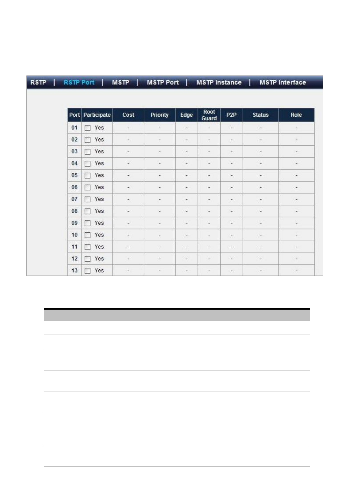
4.5.2 RSTP Port
RSTP port settings control and monitor per port spanning tree status.
User’s Manual of WGSW-48000
The page includes the following fields:
Object Description
• Port
• Participate
• Cost
• Priority
• Edge
• Root Guard
Figure 4-5-5 RSTP Port
Indicates the port numbers of the system.
Indicates if the port is runung RSTP protocol or not.
Indicates the cost of this port, which means the contribution of this port to the
path cost of paths towards the spanning tree root which include this port.
Indicates the priority of this port. This is the value of the priority field contained in
the first octect of the Port ID.
Indicates if this port is the edge port. Once configured as an edge port, the port
state immediately transitions from disable/block to forwarding state.
Indicates if this port is the root guard port. Once configured as a root guard port,
the port can prevent outside swit Displays the RSTP port status.ch with suprior
BID from affecting former topology.
• P2P
Indicates if this port is a point-to-point link. If you connect a port to another port
though a point-to-point link and the local port becomes a designated port, it
74
Page 75
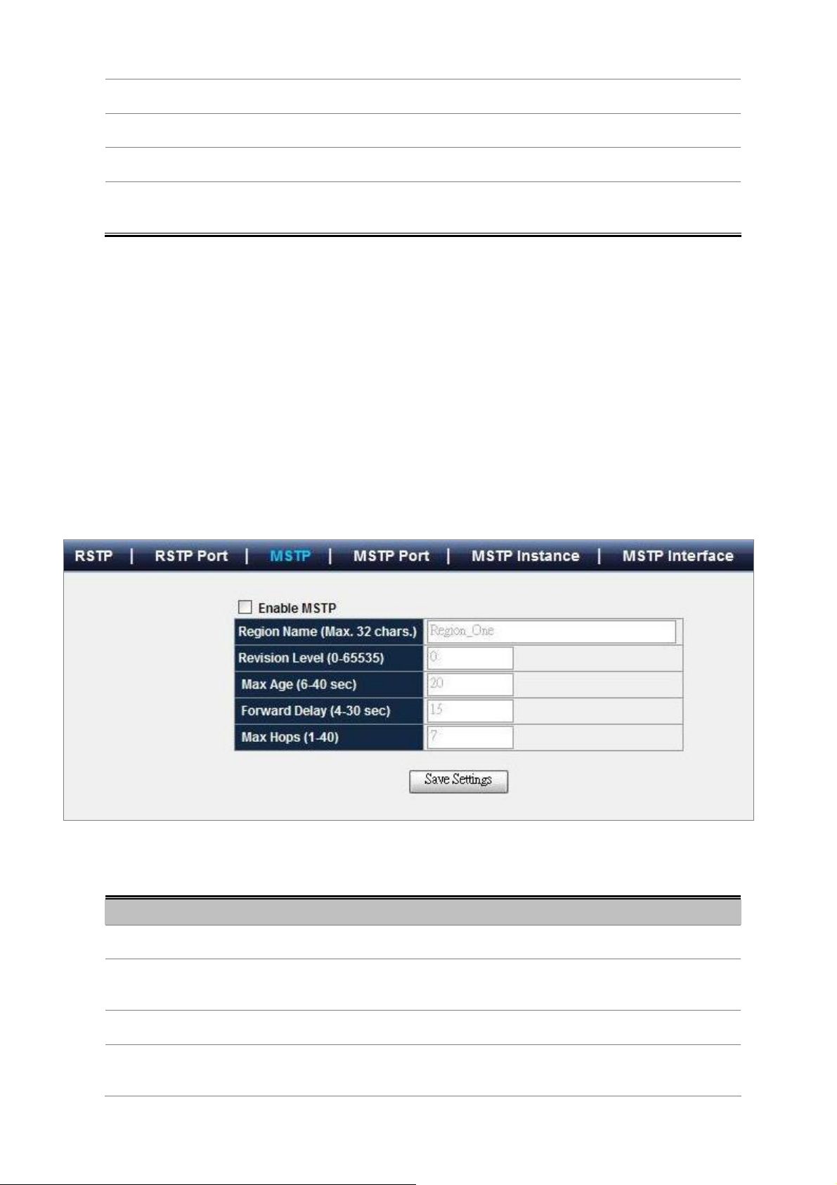
User’s Manual of WGSW-48000
negotiates a rapid transition with the other port to ensure a loop-free topology.
• Status
• Role
• Edit RSTP Port
Property
Displays the RSTP port status.
Displays the role of this RSTP port.
Click on this button to allow you to configure RSTP port properties.
4.5.3 MSTP
The Multiple Spanning Tree Protocol (MSTP) algorithm and protocol provides simple and full connectivity for frames assigned
to any given VLAN throughout a Bridged Local Area Network comprising arbitrarily interconnected Bridges, each operating
MSTP, STP (Clause 8 of IEEE Std 802.1D, 1998 Edition), or RSTP (Clause 17 of IEEE Std 802.1D,1998 Edition).
MSTP allows frames assigned to different VLANs to follow separate paths, each based on an independent Multiple Spanning
Tree Instance (MSTI), within Multiple Spanning Tree (MST) Regions composed of LANs and or MST Bridges. These Regions
and the other Bridges and LANs are connected into a single Common Spanning Tree (CST).
Figure 4-5-6 MSTP
The page includes the following fields:
Object Description
• Enable MSTP
• Region Name
• Revision Level
• Max Age
Enable or disable MSTP capability.
Specifies the configuration region name. The name string has a maximum length
of 32 characters and is case sensitive.
Specifies the configuration revision level. The range is 0 to 65535.
Configures the maximum age of the current bridge. This is the maximum age of
spanning tree protocol information learned from the network on any port before it
75
Page 76

User’s Manual of WGSW-48000
is discarded.
• Forward Delay
• Max Hops
4.5.4 MSTP Port
Forward delay is a time value which controls how fast a port changes its state.
The value determines how long the port stays in each of the listening and
learning states which precede the forward state. This value is also used to age all
dynamic entries in the forwarding databases when a topology change has been
detected and is underway.
Note: Max Age <= 2*(Forward Delay-1)
Specifies the number of hops in a region before the BPDU is discarded and the
information held for a port is aged.
Figure 4-5-7 MSTP Port
The page includes the following fields:
Object Description
• MSTP Port Settings
• Port
• Edge
The MSTP Port Settings configure MSTP port parameters.
Indicates the port numbers of the system.
Indicates if this port is the edge port. Once configured as an edge port, the port
state immediately transitions from disable/block to forwarding state.
76
Page 77
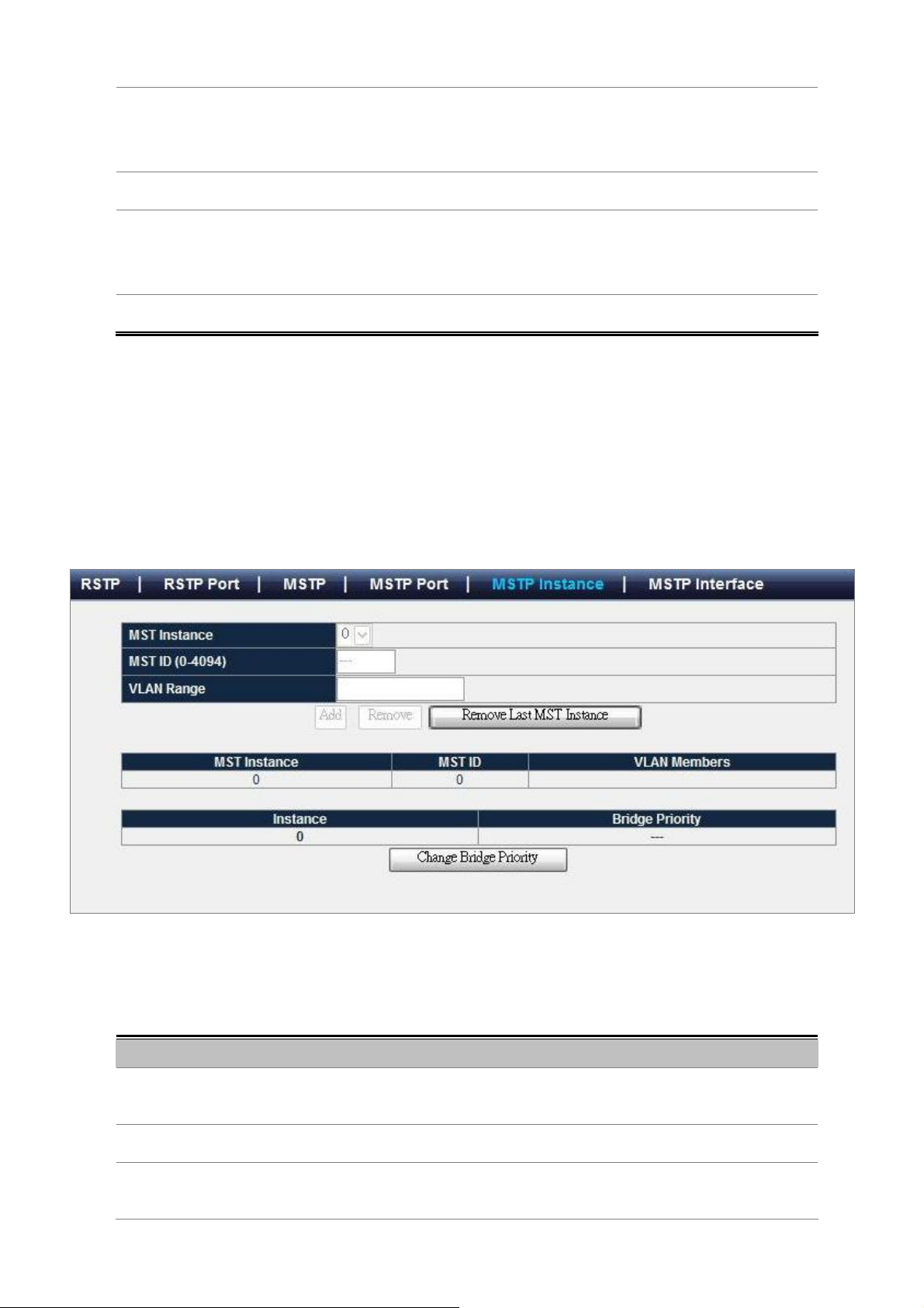
User’s Manual of WGSW-48000
• P2P
• Migration Check
• Path Cost
• Port Priority
Indicates if this port is a point-to-point link. If you connect a port to another port
though a point-to-point link and the local port becomes a designated port, it
negotiates a rapid transition with the other port to ensure a loop-free topology.
Re-checks the appropriate BPDU format to send on this port.
Displays the cost of this port for the specified MST instance.
"Cost" means the contribution of this port to the path cost of paths towards the
spanning tree root which include this port.
Displays the priority of this port for the specified MST instance.
4.5.5 MSTP Instance
MSTP operation maps VLANs into STP instances. Packets assigned to various VLANs are transmitted along different paths
within Multiple Spanning Tree Regions (MST Regions). Regions are one or more Multiple Spanning Tree bridges by which
frames can be transmitted. In configuring MST, the MST region to which the device belongs is defined. A configuration consists
of the name, revision, and region to which the device belongs.
Figure 4-5-8 MSTP Instance
The page includes the following fields:
Object Description
• MST Instance
• MST ID
• VLAN Range
Specifies the instance to configure.
This system can support up to 16 MSTP instances.
Specifies the instance identifier. the range is 0 to 4094.
Specifies vlan-range, the range is 1 to 4094. To specify a VLAN range, use a
hyphen; for example, 1-63 means VLANs 1 through 63. To specify a VLAN
77
Page 78
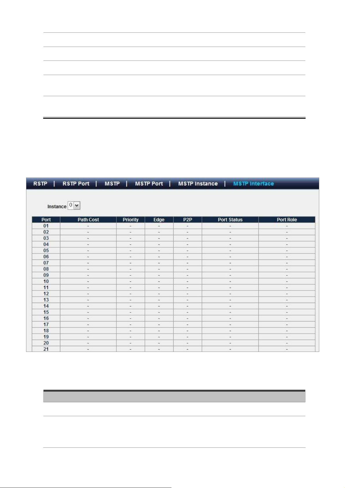
User’s Manual of WGSW-48000
series, use a comma; for example, 10,20,30 means VLANs 10, 20, and 30.
• "Add"
• "Remove"
• "Remove the last MST
instance"
• Change Bridge Priority
Creates a MST instance, map VLANs to a MST instance.
Remove VLANs from the specified MST instance.
Removes the last created MST instance.
Specifies the selected spanning tree instance device priority. The field range is
0-61440
4.5.6 MSTP Interface
Network Administrators can assign MSTP Interface settings through the "MSTP Port" page.
Figure 4-5-9 MSTP Interface
The page includes the following fields:
Object Description
• Instance
• Cost
Specifies the MST instance.
Displays the cost of this port for the specified MST instance. "Cost" means the
contribution of this port to the path cost of paths towards the spanning tree root
which include this port.
78
Page 79

User’s Manual of WGSW-48000
• Priority
• Edge
• P2P
• Status
• Role
Displays the priority of this port for the specified MST instance.
Indicates if this port is the edge port. Once configured as an edge port, the port
state immediately transitions from disable/block to forwarding state.
Indicates if this port is a point-to-point link. If you connect a port to another port
though a point-to-point link and the local port becomes a designated port, it
negotiates a rapid transition with the other port to ensure a loop-free topology.
Displays the MSTP port status for the specified MST instance.
Displays the role of this port for the specified MST instance.
79
Page 80

User’s Manual of WGSW-48000
4.6 Multicast
4.6.1 IGMP Snooping
The Internet Group Management Protocol (IGMP) lets host and routers share information about multicast groups
memberships. IGMP snooping is a switch feature that monitors the exchange of IGMP messages and copies them to the CPU
for feature processing. The overall purpose of IGMP Snooping is to limit the forwarding of multicast frames to only ports that are
a member of the multicast group.
About the Internet Group Management Protocol (IGMP) Snooping
Computers and network devices that want to receive multicast transmissions need to inform nearby routers that they will
become members of a multicast group. The Internet Group Management Protocol (IGMP) is used to communicate this
information. IGMP is also used to periodically check the multicast group for members that are no longer active. In the case
where there is more than one multicast router on a sub network, one router is elected as the ‘queried’. This router then keeps
track of the membership of the multicast groups that have active members. The information received from IGMP is then used to
determine if multicast packets should be forwarded to a given sub network or not. The router can check, using IGMP, to see if
there is at least one member of a multicast group on a given subnet work. If there are no members on a sub network, packets
will not be forwarded to that sub network.
Figure 4-6-1 Multicast Service
80
Page 81

User’s Manual of WGSW-48000
Figure 4-6-2 Multicast flooding
Figure 4-6-3 IGMP Snooping multicast stream control
IGMP Versions 1 and 2
81
Page 82

User’s Manual of WGSW-48000
Multicast groups allow members to join or leave at any time. IGMP provides the method for members and multicast routers to
communicate when joining or leaving a multicast group.
IGMP version 1 is defined in RFC 1112. It has a fixed packet size and no optional data.
The format of an IGMP packet is shown below:
IGMP Message Format
Octets
0 8 16 31
Type Response Time
Group Address (all zeros if this is a query)
The IGMP Type codes are shown below:
Type Meaning
0x11
Membership Query (if Group Address is 0.0.0.0)
Specific Group Membership Query (if Group Address is
0x11
Present)
0x16 Membership Report (version 2)
0x17 Leave a Group (version 2)
0x12 Membership Report (version 1)
Checksum
IGMP packets enable multicast routers to keep track of the membership of multicast groups, on their respective sub networks.
The following outlines what is communicated between a multicast router and a multicast group member using IGMP.
A host sends an IGMP “report” to join a group
A host will never send a report when it wants to leave a group (for version 1).
A host will send a “leave” report when it wants to leave a group (for version 2).
Multicast routers send IGMP queries (to the all-hosts group address: 224.0.0.1) periodically to see whether any group members
exist on their sub networks. If there is no response from a particular group, the router assumes that there are no group members
on the network.
The Time-to-Live (TTL) field of query messages is set to 1 so that the queries will not be forwarded to other sub networks.
IGMP version 2 introduces some enhancements such as a method to elect a multicast queried for each LAN, an explicit leave
message, and query messages that are specific to a given group.
The states a computer will go through to join or to leave a multicast group are shown below:
82
Page 83

User’s Manual of WGSW-48000
Non-Member
Leave Group
(Stop Timer)
Delaying Member Idle Member
Join Group
(Send Report,
Start Timer)
Query Received
(Start Timer)
Report Received
(Stop Timer)
Timer Expried
(Send report)
Leave Group
Figure 4-6-4 IGMP State Transitions
IGMP Querier –
A router, or multicast-enabled switch, can periodically ask their hosts if they want to receive multicast traffic. If there is more
than one router/switch on the LAN performing IP multicasting, one of these devices is elected “querier” and assumes the
role of querying the LAN for group members. It then propagates the service requests on to any upstream multicast
switch/router to ensure that it will continue to receive the multicast service.
Multicast routers use this information, along with a multicast routing protocol such as
DVMRP or PIM, to support IP multicasting across the Internet.
83
Page 84

User’s Manual of WGSW-48000
4.6.2 Static Multicast
Static multicast groups provides a way to add and delete multicast addresses in the L2 address table.
Figure 4-6-5 Static Multicast
The page includes the following fields:
Object Description
• Group Name
• VLAN ID
• MAC Address
• Port
Inserts a symbolic name for easy maintenance for this multicast group.
Specifies a VLAN ID for this multicast group(1 - 4094).
Specifies a L2 multicast address(Format: 01:XX:XX:XX:XX:XX).
Specifies the multicast port members.
4.6.3 Static Multicast Table
The IGMP Static Multicast Table allowed the network administrator to assigning a specificy Multicast Group to a port. The port is
configured to send and receive all traffic for a particular mulcast group. Usually, the function is use to test the multicast protocols
in the network or for the PC/Laptop manufactory to pre-install operation system via multicast. There is maximum 128 static
Multicast Groups are able to assign.
84
Page 85

User’s Manual of WGSW-48000
Figure 4-6-6 Static Multicast Table
The page includes the following fields:
Object Description
• Group ID
• Group Name
• VLAN ID
• Multicast Address
• Member Port
• Modify
• Delete
The index for this static multicast group.
The name for this static multicast group.
The VLAN ID for this static multicast group.
The multicast address for this static multicast group.
The port members for this static multicast group.
Specifies the states of port member for this static multicast group.
To destroy the existing multicast group.
Figure 4-6-7 Static Multicast Table
85
Page 86

User’s Manual of WGSW-48000
4.6.4 IGMP
IGMP is a standard defined in RFC1112 for IGMPv1, and in RFC2236 for IGMPv2. IGMP specifies how a host can register a
router in order to receive specific multicast traffic. Configure the switch to use IGMP snooping in subnets that receive IGMP
queries from either IGMP or the IGMP snooping querier. IGMP snooping constrains multicast traffic at Layer 2 by configuring
Layer 2 LAN ports dynamically to forward multicast traffic only to those ports that want to receive it.
The page includes the following fields:
Object Description
• Assign Router Ports
• Dynamic Router Port
• Group Membership
• VLAN ID
• Group Address
• Member Port(s)
Figure 4-6-7 IGMP
Specify ports to which IGMP routers were connected.
Click on this button to display the port that receive the following traffic.
1. IGMP Query
2. Packet with destination IP 224.0.0.2
Click on this button to display the IGMP groups information.
Indicates the VLAN ID of the specified multicast group.
Indicates IPv4 multicast group address of the group being reported.
Indicates the membership associated with the group.
86
Page 87

User’s Manual of WGSW-48000
4.7 Security
This section is to control the security access of the switch, includes the user access and management control.
The Security function contains links to the following topics:
• Port Security
• ACL
• RADIUS
• TACACS+
• 802.1x Settings
4.7.1 Port Security
Port security is a feature that allows you to configure a switch port with one or more device MAC addresses that are authorized
to access the network through that port.
When port security is enabled on a port, the Managed Switch stops learning new MAC addresses on the specified port when it
has reached a configured maximum number. Only incoming traffic with source addresses already stored in the dynamic or static
address table will be authorized to access the network through that port. If a device with an unauthorized MAC address attempts
to use the switch port, the intrusion will be detected and the switch can automatically take action by disabling the port and
sending a trap message.
Figure 4-7-1 Port Security main screen
The page includes the following fields:
Object Description
• Port
• Security Mode
• Max Entries
Selects a specific port to configure.
Specifies the port security mode
None: Disable port security on the port.
Dynamic: Determines dynamic learning mode with accept function.
It associates with Dynamic mode and indicates the maximum SA addresses can be
learnt( 0~24 ) on this port.
87
Page 88

User’s Manual of WGSW-48000
Figure 4-7-2 Port Security – current security table
4.7.2 ACL
An ACL consists of a set of rules which are matched sequentially against a packet. When a packet meets the match criteria of a
rule, the specified rule action (Permit / Deny) is taken and the additional rules are not checked for a match. On this menu the
interfaces to which an ACL applies must be specified, as well as whether it applies to inbound or outbound traffic. Rules for the
ACL are specified/created using the ACL Rule Configuration menu.
ACL is an acronym for Access Control List. It is the list table of ACEs, containing access control entries that specify individual
users or groups permitted or denied to specific traffic objects, such as a process or a program.
Each accessible traffic object contains an identifier to its ACL. The privileges determine whether there are specific traffic object
access rights.
ACL implementations can be quite complex, for example, when the ACEs are prioritized for the various situation. In networking,
the ACL refers to a list of service ports or network services that are available on a host or server, each with a list of hosts or
servers permitted or denied to use the service. ACL can generally be configured to control inbound traffic, and in this context,
they are similar to firewalls.
ACE is an acronym for Access Control Entry. It describes access permission associated with a particular ACE ID.
There are three ACE frame types (Ethernet Type, ARP, and IPv4) and two ACE actions (permit and deny). The ACE also
88
Page 89

User’s Manual of WGSW-48000
contains many detailed, different parameter options that are available for individual application.
The page includes the following fields:
Object Description
• Sort By
• Entry Name
• Permit
• Deny
• Queue Assignment
• Port List
• Proiority
Defines the type of sort. It includes priority, deny and permit.
Indicates the name of ACL entry. The length of name have to be smaller than 20. And
Different ACL entries can't have the same name.
Frames matching the ACL entries may be forwarded and learned.
Frames matching the ACL entries are dropped.
Select a traffic class of Low, Normal, Medium, or High to apply to the ACL.
Indicates the ports ,ACL entry apply to.
When add new entry default to all ports,so you can click "modify" linker to modify it.
Indicates the priority of ACL entry. The largest value have highest priority.
The range is from 0 to 65535. And Different ACL entries can't have the same priority.
Figure 4-7-3 Access Control List main page
+ increase priority by 1.
- decrease priority by 1.
• Delete
By which deletes the selected ACL.
89
Page 90

User’s Manual of WGSW-48000
• New Entry
• Import
• Export
• Save Settings
Create new ACL entry
Inserts a new ACL entry.
Selects an XML file to import.
Writes all ACL entries to an XML file.
Modifies the changes of ACL entries which are shown on this page.
Figure 4-7-4 Access Control List – add new ACL entry
The Page contains the following fields:
• Entry Name
• Priority
IP ACL
• SIP
(Source IP Address)
Defines a new user-defined IP based ACL
Indicates the priority of ACL entry. The largest value have highest priority.
The range is from 0 to 65535. And Different ACL entries can't have the same priority.
Matches the source port IP address to which packets are addressed to the ACE. And it's
format is w.x.y.z .
90
Page 91

User’s Manual of WGSW-48000
• MASK
• DIP
(Destination IP Address)
• MASK
• SRC Port
• DST Port
• Packet Type
Defines the source IP address mask.
Matches the destination port IP address to which packets are addressed to the ACE. And
it's format is w.x.y.z .
Defines the destination IP address mask
Defines the TCP/UDP source port to which the ACE is matched. This field is active only if
800/6-TCP or 800/17-UDP is selected in the Select from List drop-down menu.
The possible field range is 0 - 65535
Defines the TCP/UDP destination port. This field is active only if 800/6-TCP or
800/17-UDP is selected in the Select from List drop-down menu.
The possible field range is 0 - 65535
Where selects from a protocols list on which ACE can be based. The possible field values
are:
• ICMP, which indicates that the Internet Control Message Protocol (ICMP) is used to
classify network flows.
MAC ACL
• MAC SA
• MASK
• MAC DA
• IGMP, which indicates that the Internet Group Management Protocol (IGMP) is used
to classify network flows.
• TCP, which indicates that the Transmission Control Protocol is used to classify
network flows.
• UDP, which indicates that the User Datagram Protocol is used to classify network
flows.
• IP, which indicates that all IPv4 frames are used to classify network flows.
• GRE , which indicates that the Generic Routing Encapsulation (GRE) protocol is used
to classify network flows.
Matches the source MAC address to which packets are addressed to the ACE. And it's
format is XX-XX-XX-XX-XX-XX.
Defines the source MAC address mask.
Where matches the destination MAC address to which packets are addressed to the ACE.
And it's format is XX-XX-XX-XX-XX-XX.
• Ether Type
• 802.1Q VLAN ID
• Add Entry
Means destination TCP/UDP port number.
The range is from 1 to 65535.
When "Specific" is selected for the VLAN ID filter, you can enter a specific VLAN ID
number. The allowed range is 1 to 4095. A frame that hits this ACE matches this VLAN ID
value.
Inserts this ACL entry.
91
Page 92

ACL Port select
User’s Manual of WGSW-48000
Figure 4-7-5 ACL Port List
1. If the rule/filter of ACL entry is empty, the check box of this entry will not be checked by default.
2. If the check box is not checked, the corresponding ACL entry will not be programmed to hardware.
3. Before input MAC, IP, port number, Packet type or Ether type, you have to check the corresponding
check box of rule/filter.
4. The count of ACL entries which own PORT rule/filter have to be smaller than 8, otherwise it would
cause NO RESOURCE when add ACL entry.
4.7.3 802.1x
Overview of 802.1X Port-Based Authentication
In the 802.1X-world, the user is called the supplicant, the switch is the authenticator, and the RADIUS server is the
authentication server. The switch acts as the man-in-the-middle, forwarding requests and responses between the supplicant
and the authentication server. Frames sent between the supplicant and the switch are special 802.1X frames, known as EAPOL
(EAP Over LANs) frames. EAPOL frames encapsulate EAP PDUs (RFC3748). Frames sent between the switch and the
RADIUS server are RADIUS packets. RADIUS packets also encapsulate EAP PDUs together with other attributes like the
switch's IP address, name, and the supplicant's port number on the switch. EAP is very flexible, in that it allows for different
authentication methods, like MD5-Challenge, PEAP, and TLS. The important thing is that the authenticator (the switch) doesn't
need to know which authentication method the supplicant and the authentication server are using, or how many information
exchange frames are needed for a particular method. The switch simply encapsulates the EAP part of the frame into the
relevant type (EAPOL or RADIUS) and forwards it.
When authentication is complete, the RADIUS server sends a special packet containing a success or failure indication. Besides
forwarding this decision to the supplicant, the switch uses it to open up or block traffic on the switch port connected to the
92
Page 93
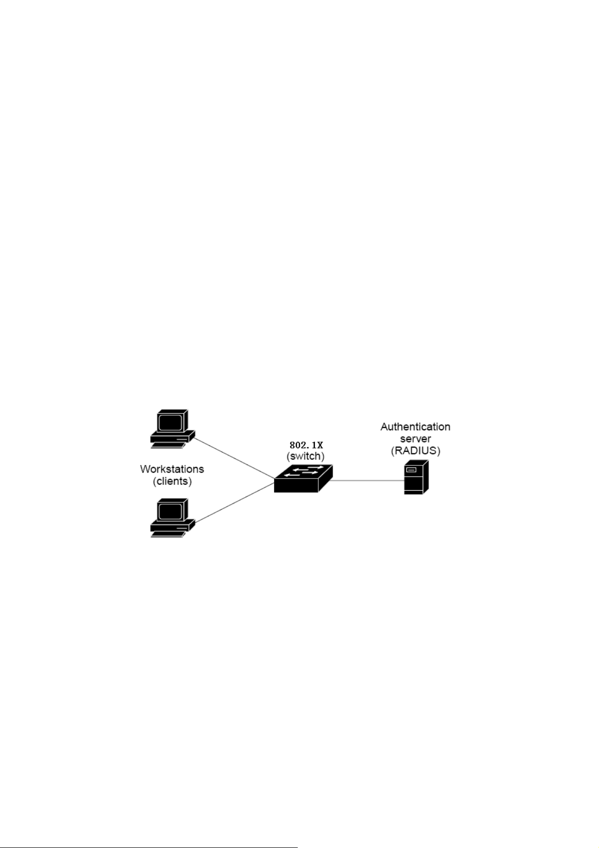
User’s Manual of WGSW-48000
supplicant.
4.7.3.1 Understanding IEEE 802.1X Port-Based Authentication
The IEEE 802.1X standard defines a client-server-based access control and authentication protocol that restricts unauthorized
clients from connecting to a LAN through publicly accessible ports. The authentication server authenticates each client
connected to a switch port before making available any services offered by the switch or the LAN.
Until the client is authenticated, 802.1X access control allows only Extensible Authentication Protocol over LAN (EAPOL)
traffic through the port to which the client is connected. After authentication is successful, normal traffic can pass through the
port.
This section includes this conceptual information:
• Device Roles
• Authentication Initiation and Message Exchange
• Ports in Authorized and Unauthorized States
Device Roles
With 802.1X port-based authentication, the devices in the network have specific roles as shown below.
Figure 4-7-6 Device Roles
z Client—the device (workstation) that requests access to the LAN and switch services and responds to requests from
the switch. The workstation must be running 802.1X-compliant client software such as that offered in the Microsoft
Windows XP operating system. (The client is the supplicant in the IEEE 802.1X specification.)
z Authentication server—performs the actual authentication of the client. The authentication server validates the
identity of the client and notifies the switch whether or not the client is authorized to access the LAN and switch services.
Because the switch acts as the proxy, the authentication service is transparent to the client. In this release, the Remote
Authentication Dial-In User Service (RADIUS) security system with Extensible Authentication Protocol (EAP)
extensions is the only supported authentication server; it is available in Cisco Secure Access Control Server version 3.0.
RADIUS operates in a client/server model in which secure authentication information is exchanged between the
93
Page 94

User’s Manual of WGSW-48000
RADIUS server and one or more RADIUS clients.
z Switch (802.1X device)—controls the physical access to the network based on the authentication status of the client.
The switch acts as an intermediary (proxy) between the client and the authentication server, requesting identity
information from the client, verifying that information with the authentication server, and relaying a response to the client.
The switch includes the RADIUS client, which is responsible for encapsulating and decapsulating the Extensible
Authentication Protocol (EAP) frames and interacting with the authentication server. When the switch receives
EAPOL frames and relays them to the authentication server, the Ethernet header is stripped and the remaining EAP
frame is re-encapsulated in the RADIUS format. The EAP frames are not modified or examined during encapsulation,
and the authentication server must support EAP within the native frame format. When the switch receives frames from
the authentication server, the server's frame header is removed, leaving the EAP frame, which is then encapsulated for
Ethernet and sent to the client.
Authentication Initiation and Message Exchange
The switch or the client can initiate authentication. If you enable authentication on a port by using the dot1x port-control auto
interface configuration command, the switch must initiate authentication when it determines that the port link state transitions
from down to up. It then sends an EAP-request/identity frame to the client to request its identity (typically, the switch sends an
initial identity/request frame followed by one or more requests for authentication information). Upon receipt of the frame, the
client responds with an EAP-response/identity frame.
However, if during bootup, the client does not receive an EAP-request/identity frame from the switch, the client can initiate
authentication by sending an EAPOL-start frame, which prompts the switch to request the client's identity
If 802.1X is not enabled or supported on the network access device, any EAPOL frames from the
client are dropped. If the client does not receive an EAP-request/identity frame after three attempts
to start authentication, the client transmits frames as if the port is in the authorized state. A port in
the authorized state effectively means that the client has been successfully authenticated.
When the client supplies its identity, the switch begins its role as the intermediary, passing EAP frames between the client and
the authentication server until authentication succeeds or fails. If the authentication succeeds, the switch port becomes
authorized.
The specific exchange of EAP frames depends on the authentication method being used. “Figure 4-7-7” shows a message
exchange initiated by the client using the One-Time-Password (OTP) authentication method with a RADIUS server.
94
Page 95
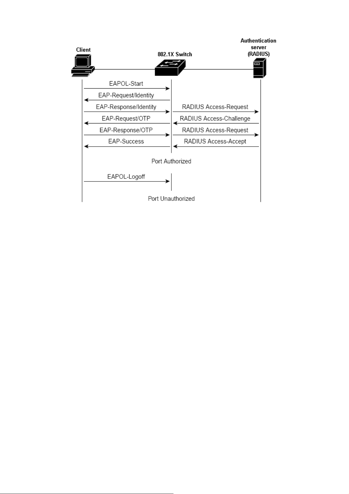
User’s Manual of WGSW-48000
Figure 4-7-7 EAP message exchange
Ports in Authorized and Unauthorized States
The switch port state determines whether or not the client is granted access to the network. The port starts in the unauthorized
state. While in this state, the port disallows all ingress and egress traffic except for 802.1X protocol packets. When a client is
successfully authenticated, the port transitions to the authorized state, allowing all traffic for the client to flow normally.
If a client that does not support 802.1X is connected to an unauthorized 802.1X port, the switch requests the client's identity. In
this situation, the client does not respond to the request, the port remains in the unauthorized state, and the client is not granted
access to the network.
In contrast, when an 802.1X-enabled client connects to a port that is not running the 802.1X protocol, the client initiates the
authentication process by sending the EAPOL-start frame. When no response is received, the client sends the request for a
fixed number of times. Because no response is received, the client begins sending frames as if the port is in the authorized state
If the client is successfully authenticated (receives an Accept frame from the authentication server), the port state changes to
authorized, and all frames from the authenticated client are allowed through the port. If the authentication fails, the port remains
in the unauthorized state, but authentication can be retried. If the authentication server cannot be reached, the switch can
retransmit the request. If no response is received from the server after the specified number of attempts, authentication fails,
and network access is not granted.
When a client logs off, it sends an EAPOL-logoff message, causing the switch port to transition to the unauthorized state.
If the link state of a port transitions from up to down, or if an EAPOL-logoff frame is received, the port returns to the unauthorized
state.
95
Page 96

4.7.3.2 802.1x Port Configuration
The Port Authentication function establishes security between ports.
User’s Manual of WGSW-48000
The page includes the following fields:
Object Description
• Enable 802.1X
• Status
• Client MAC
Address
• Authorization
Enables or disables 802.1X function.
Enables or disables port authentication.
Displays the last client in the MAC address who send out the EAPOL control frame of
the port.
Displays the authentication status of an enabled port.
• In Progress: Indicates that the authentication is still in progress. Traffic is not
Figure 4-7-8 802.1X port configuration
• Enabled checked means these ports should be authorized by a RADIUS server to
forward traffic. No traffic is forwarded if it is unauthorized.
• Otherwise, no authentication process is required for those ports; all traffic could be
forwarded normally.
forwarded before authentication is verified.
• N/A: means no authentication required.
96
Page 97

User’s Manual of WGSW-48000
4.7.3.3 Windows Platform RADIUS Server Configuration
1. Setup the RADIUS server and assign the client IP address to the Managed switch. In this case, field in the default IP
Address of the Managed Switch with 192.168.0.100. And also make sure the shared secret key is as same as the one
you had set at the switch RADIUS server – 12345678 at this case.
Figure 4-7-9 Windows Server RADIUS Server setting
2. Configure ports attribute of 802.1X, the same as “802.1X Port Configuration”.
Figure 4-7-10 802.1x Port Configuration
3. Create user data. That step are different of “Local Authenticate”, the establishment of the user data needs to be
created on the Radius Server PC. For example, the Radius Server founded on Win2000 Server, and then:
97
Page 98

User’s Manual of WGSW-48000
Figure 4-7-11Windows Server RADIUS Server setting path
5. Enter ” Active Directory Users and Computers”, create legal user data, the next, right-click a user what you created to
enter properties, and what to be noticed:
Figure 4-7-12 TsInternetUser Properties screen
98
Page 99

User’s Manual of WGSW-48000
Set the Ports Authenticate Status to “Disable” if the port is connected to the RADIUS server or the
port is a uplink port that is connected to another switch. Or once the 802.1X stat to work, the switch
might not be able to access the RADIUS server.
4.7.3.4 802.1X Client Configuration
Windows XP is originally 802.1X support. As to other operating systems (windows 98SE, ME, 2000), an 802.1X client utility is
needed. The following procedures show how to configure 802.1X Authentication in Windows XP.
Please note that if you want to change the 802.1x authentication type of a wireless client, i.e. switch to EAP-TLS from EAP-MD5,
you must remove the current existing wireless network from your preferred connection first, and add it in again.
Configure Sample: EAP-MD5 Authentication
1. Go to Start > Control Panel, double-click on “Network Connections”.
2. Right-click on the Local Network Connection.
3. Click “Properties” to open up the Properties setting window.
Figure 4-7-13 Client’s NIC
4. Select “Authentication” tab.
5. Select “Enable network access control using IEEE 802.1X” to enable 802.1x authentication.
6. Select “MD-5 Challenge” from the drop-down list box for EAP type.
99
Page 100

User’s Manual of WGSW-48000
Figure 4-7-14 802.1x client configuration
7. Click “OK”.
8. When client has associated with the Managed Switch, a user authentication notice appears in system tray. Click on the
notice to continue.
Figure 4-7-15 802.1x client port-based authentication
100
 Loading...