

Page 1

User’s Manual of WGSW-28040 / 28040P / 28040P4
1
WGSW-28040
28-Port 10/100/1000M bps with
4 Shared SFP
User’s Manual
Managed Gigabit Switch
WGSW-28040P / WGSW-28040P4
24-Port 10/100/1000M bps PoE
+ 4-Port Gigabit TP/SFP Combo
Managed Switch
Page 2

User’s Manual of WGSW-28040 / 28040P / 28040P4
2
Trademarks
Copyright © PLANET Technology Corp. 2012.
Contents subject to which revision without prior notice.
PLANET is a registered trademark of PLANET Technology Corp. All other trademarks belong to their respective owners.
Disclaimer
PLANET Technology does not warrant that the hardware will work properly in all environments and applications, and makes no
warranty and representation, either implied or expressed, with respect to the quality, performance, merchantability, or fitness for
a particular purpose. PLANET has made every effort to ensure that this User's Manual is accurate; PLANET disclaims liability
for any inaccuracies or omissions that may have occurred.
Information in this User's Manual is subject to change without notice and does not represent a commitment on the part of
PLANET. PLANET assumes no responsibility for any ina ccur acie s t hat may be contained in this User's Manual. PLAN ET makes
no commitment to updat e or k eep curr en t the information in this User's Manual, and re serv es th e ri ght t o m ake i mprov em ent s to
this User's Manual and/or to the products described in this User's Manual, at any time without notice.
If you find information in this manual that is incorrect, misleading, or incomplete, we would appreciate your comments and
suggestions.
FCC Warning
This equipment has been tested and found to comply with the limits for a Class A digital device, pursuant to Part 15 of the FCC
Rules. These limits are designed to provide reasonable protection against harmful interference when the equipment is operated
in a commercial environment. This equipment generates, uses, and can radiate radio frequency energy and, if not installed and
used in accordance with the Instruction manual, may cause harmful interference to radio communications. Operation of this
equipmen t in a residential area is likely to cause harmful interference in which case the user will be required to correct the
interference at whose own expense.
CE Mark Warning
This is a Class A product. In a domestic environment, this product may cause radio interference, in which case the user may be
required to take adequate measures.
Energy Saving Note of the Device
This power required device does not support Standby mode operation.
For energy saving, please remove the power cable to disconnect the device from the power circuit.
Without re moving power cable, the device will still consuming power from the power source. In the view of Saving the Energy
and reduce the unnecessary power consuming, it is strongly suggested to remove the power connection for the device if this
device is not intended to be active.
WEEE Warning
To avoid the potential effects on the environment and human health as a result of the presence of
hazardous substances in electrical and electronic equipment, end users of electrical and electronic
equipment should understand the meaning of the crossed-out wheeled bin symbol. Do not dispose of
WEEE as unsorted municipal w aste and have to colle ct such WEEE separately.
Revision
PLANET 28-Port 10/100/1000Mbps with 4 Shared SFP Managed Gigabit Switch User's Manual
FOR MODELS: WGSW-28040 / WGSW-28040P / WGSW-28040P4
REVISION: 1.3 (January.2012)
Part No: EM-WGSW-28040_28040P (2080-A93230-00)
Page 3

User’s Manual of WGSW-28040 / 28040P / 28040P4
3
TABLE OF CONETNTS
1. INTRODUTION .................................................................................................................... 15
1.1 Packet Contents ......................................................................................................................................... 15
1.2 Product Description ................................................................................................................................... 16
1.3 How to Use This Manual ............................................................................................................................ 18
1.4 Product Features ........................................................................................................................................ 18
1.5 Product Specificatio n ................................................................................................................................ 21
2. INSTALLATION ................................................................................................................... 23
2.1 Hardware Description ................................................................................................................................ 23
2.1.1 Switch Front Panel .............................................................................................................................................. 23
2.1.2 LED Indications ................................................................................................................................................... 24
2.1.3 Switch Rear Panel ............................................................................................................................................... 26
2.2 Install the Switch ........................................................................................................................................ 28
2.2.1 Desktop Installation ............................................................................................................................................. 28
2.2.2 Rack Mounting ..................................................................................................................................................... 29
2.2.3 Installing the SFP transceiver .............................................................................................................................. 30
3. SWITCH MANAGEMENT .................................................................................................... 33
3.1 Requirements .............................................................................................................................................. 33
3.2 Management Access Overview ................................................................................................................. 34
3.3 Administrati on Console ............................................................................................................................. 34
3.4 Web Management ....................................................................................................................................... 36
3.5 SNMP-Based Network Management ......................................................................................................... 37
4. WEB CONFIGURATION ...................................................................................................... 38
4.1 Main Web Page ........................................................................................................................................... 41
4.2 System ......................................................................................................................................................... 43
4.2.1 System Information .............................................................................................................................................. 44
4.2.2 IP Configuration ................................................................................................................................................... 45
4.2.3 IPv6 Configuration ............................................................................................................................................... 47
4.2.4 User Configuration ............................................................................................................................................... 49
Page 4

User’s Manual of WGSW-28040 / 28040P / 28040P4
4
4.2.5 Enable Password ................................................................................................................................................. 50
4.2.6 SNTP Configuration ............................................................................................................................................. 51
4.2.7 Log Management ................................................................................................................................................. 52
4.2.7.1 Local Log ................................................................................................................................................... 53
4.2.7.2 Remote Syslog .......................................................................................................................................... 54
4.2.7.3 Log View .................................................................................................................................................... 56
4.2.8 SNMP Management ............................................................................................................................................ 58
4.2.8.1 SNMP Overview ........................................................................................................................................ 58
4.2.8.2 SNMP System Information ........................................................................................................................ 59
4.2.8.3 SNMP View Table ...................................................................................................................................... 60
4.2.8.4 SNMP Access Group ................................................................................................................................. 61
4.2.8.5 SNMP Community ..................................................................................................................................... 62
4.2.8.6 SNMP User................................................................................................................................................ 63
4.2.8.7 SNMP Engine ID ....................................................................................................................................... 65
4.2.8.8 SNMP Trap Host ........................................................................................................................................ 65
4.3 Port Management ....................................................................................................................................... 67
4.3.1 Port Configuration ................................................................................................................................................ 67
4.3.2 Port Statistics ..................................................................................................................................................... 69
4.3.3 Port Counters ...................................................................................................................................................... 71
4.3.4 Port Error Disabled .............................................................................................................................................. 75
4.3.5 Port Mirroring ....................................................................................................................................................... 76
4.3.6 Jumbo Frame ...................................................................................................................................................... 78
4.3.7 Protected Ports .................................................................................................................................................... 79
4.3.8 Bandwidth Control ............................................................................................................................................... 81
4.3.8.1 Preamble Setting ....................................................................................................................................... 81
4.3.8.2 Port Rate Setting ....................................................................................................................................... 82
4.3.9 Bandwidth Utilization ........................................................................................................................................... 84
4.4 Link Aggregation ........................................................................................................................................ 85
4.4.1 Tr unk Group ......................................................................................................................................................... 87
4.4.2 Trunk Backup Port ............................................................................................................................................... 88
4.4.3 LACP Configuration ............................................................................................................................................. 89
4.5 VLAN ............................................................................................................................................................ 91
4.5.1 VLAN Overview ................................................................................................................................................... 91
4.5.2 IEEE 802.1Q VLAN ............................................................................................................................................. 92
4.5.3 VLAN Switching ................................................................................................................................................... 95
4.5.4 VLAN Port Configuration ..................................................................................................................................... 97
4.5.5 VLAN Port Mode Setting...................................................................................................................................... 99
4.5.6 VLAN Ingress Filter ........................................................................................................................................... 100
4.5.7 QinQ .................................................................................................................................................................. 101
Page 5

User’s Manual of WGSW-28040 / 28040P / 28040P4
5
4.5.7.1 SVLAN Setting ........................................................................................................................................ 102
4.5.7.2 SVLAN Member Setting .......................................................................................................................... 103
4.5.7.3 SVLAN PVID Settings ............................................................................................................................. 104
4.5.7.4 SVLAN Service Port ................................................................................................................................ 105
4.5.8 Voice VLAN ....................................................................................................................................................... 106
4.5.8.1 Introduction to Voice VLAN ...................................................................................................................... 106
4.5.8.2 Voice VLAN Setting ................................................................................................................................. 107
4.5.8.3 Voice VLAN OUI Setting .......................................................................................................................... 108
4.5.9 Subnet VLAN Setting ......................................................................................................................................... 109
4.5.10 VLAN setting example: .................................................................................................................................... 111
4.5.10.1 Two separate 802.1Q VLAN .................................................................................................................. 111
4.5.10.2 VLAN Trunking between two 802.1Q aware switch ............................................................................... 114
4.5.10.3 Port Isolate ............................................................................................................................................ 116
4.6 Spanning Tree Protocol ........................................................................................................................... 117
4.6.1 Theory ............................................................................................................................................................... 117
4.6.2 STP Global Settings .......................................................................................................................................... 123
4.6.3 STP Port Setting ................................................................................................................................................ 126
4.6.4 MST Configuration ............................................................................................................................................. 129
4.6.5 MST Instance Setting ........................................................................................................................................ 130
4.6.6 MSTI Port Setting .............................................................................................................................................. 132
4.7 Multicast .................................................................................................................................................... 135
4.7.1 IGMP Snooping ................................................................................................................................................. 135
4.7.2 IGMP Snooping Setting ..................................................................................................................................... 139
4.7.3 IGMP VLAN Setting ........................................................................................................................................... 142
4.7.4 IGMP Querier Setting ........................................................................................................................................ 143
4.7.5 IGMP Static Group ............................................................................................................................................. 144
4.7.6 IGMP Group Table ............................................................................................................................................. 145
4.7.7 IGMP Router Setting .......................................................................................................................................... 145
4.7.8 Router Table ...................................................................................................................................................... 146
4.8 Quality of Service ..................................................................................................................................... 148
4.8.1 Understand QoS ................................................................................................................................................ 148
4.8.2 Port-based Priority ............................................................................................................................................. 149
4.8.3 802.1p-based Priority ........................................................................................................................................ 151
4.8.4 DSCP-based Priority ......................................................................................................................................... 152
4.8.5 Priority to Queue Mapping ................................................................................................................................. 154
4.8.6 Packet Scheduling ............................................................................................................................................. 155
4.8.7 Queue Weight Setting ........................................................................................................................................ 157
4.8.8 Queue Remarking Status................................................................................................................................... 159
4.8.9 Queue Remarking Table .................................................................................................................................... 160
Page 6

User’s Manual of WGSW-28040 / 28040P / 28040P4
6
4.9 Security ..................................................................................................................................................... 162
4.9.1 Storm Control ..................................................................................................................................................... 162
4.9.2 MAC Filtering ..................................................................................................................................................... 164
4.9.3 Port Security ...................................................................................................................................................... 165
4.9.4 802.1X Access Control ...................................................................................................................................... 167
4.9.4.1 Understanding IEEE 802.1X Port-Bas ed Authenti cation ......................................................................... 167
4.9.4.2 802.1X Setting ......................................................................................................................................... 171
4.9.4.3 802.1X Port Setting ................................................................................................................................. 173
4.9.4.4 Guest VLAN Setting ................................................................................................................................ 175
4.9.5 RADIUS Server Setting ..................................................................................................................................... 176
4.10 DHCP Snooping ...................................................................................................................................... 178
4.10.1 DHCP Snooping Overview .............................................................................................................................. 178
4.10.2 IP Source Guard Overview .............................................................................................................................. 179
4.10.3 DHCP Snooping Setting .................................................................................................................................. 180
4.10.4 DHCP Snooping VLAN Setting ........................................................................................................................ 181
4.10.5 DHCP Snooping Port Setting ........................................................................................................................... 182
4.10.6 DHCP Snooping Option82 Setting ................................................................................................................... 183
4.10.7 DHCP Snooping Binding Table Setting ............................................................................................................ 185
4.11 Dynamic ARP Inspection ....................................................................................................................... 186
4.11.1 Dynamic ARP Inspection Setting ..................................................................................................................... 186
4.11.2 Dynamic ARP Inspection VLAN Setting ........................................................................................................... 187
4.11.3 Dynamic ARP Inspection Port Setting .............................................................................................................. 188
4.11.4 Dynamic ARP Inspection Table Setting ............................................................................................................ 189
4.12 ACL .......................................................................................................................................................... 190
4.12.1 ACL Setting ...................................................................................................................................................... 190
4.12.2 ACE Setting ..................................................................................................................................................... 192
4.12.3 ACL Binding Port ............................................................................................................................................. 197
4.12.4 ACL Binding VLAN ........................................................................................................................................... 198
4.12.5 ACL Binding Policy .......................................................................................................................................... 199
4.12.6 ACL Template Setting ...................................................................................................................................... 200
4.12.7 ACL Index Range Setting................................................................................................................................. 201
4.12.8 ACL Policy Setting ........................................................................................................................................... 202
4.13 MAC Address Table ................................................................................................................................ 203
4.13.1 Dynamic Learned ............................................................................................................................................ 203
4.13.2 Statics MAC Table Setting ............................................................................................................................... 204
4.14 Diagnostics ............................................................................................................................................. 206
4.14.1 Ping Test .......................................................................................................................................................... 206
4.14.2 Ping IPv6 Test .................................................................................................................................................. 207
Page 7

User’s Manual of WGSW-28040 / 28040P / 28040P4
7
4.15 Power over Ethernet (WGSW-28040P / WGSW-28040P4 Only).......................................................... 209
4.15.1 Power over Ethernet Powered Device ............................................................................................................. 210
4.15.2 PoE Configuration ........................................................................................................................................... 210
4.16 Maintenance ............................................................................................................................................ 213
4.16.1 Backup Manager ............................................................................................................................................. 213
4.16.2 Upgrade Manager ............................................................................................................................................ 214
4.16.3 Save Configuration .......................................................................................................................................... 215
4.16.4 Factory Default ................................................................................................................................................ 216
4.16.5 Reboot Switch ................................................................................................................................................. 217
5. COMMAND LINE INTERFACE .......................................................................................... 218
5.1 Accessing the CLI .................................................................................................................................... 218
Logon to the Console .......................................................................................................................................... 218
Configure IP address ........................................................................................................................................... 219
5.2 Telnet Login .............................................................................................................................................. 221
6. Command Line Mode ....................................................................................................... 222
6.1 User Mode Commands ............................................................................................................................ 223
6.1.1 Show Command ................................................................................................................................................ 223
Show Version ...................................................................................................................................................... 223
Show History ....................................................................................................................................................... 223
Show Info ............................................................................................................................................................ 224
Show Privilege ..................................................................................................................................................... 224
6.1.2 Enable Command .............................................................................................................................................. 225
Enable ................................................................................................................................................................. 225
6.2 Privileged Mode Commands ................................................................................................................... 226
6.2.1 Show Command ................................................................................................................................................ 226
Show History ....................................................................................................................................................... 226
Show Startup-config ............................................................................................................................................ 226
Show Version ...................................................................................................................................................... 226
Show Running-config .......................................................................................................................................... 227
Show Privilege ..................................................................................................................................................... 227
6.2.2 Configuration Command .................................................................................................................................... 228
Config .................................................................................................................................................................. 228
6.2.3 Disable Command ............................................................................................................................................. 228
Disable ................................................................................................................................................................ 228
6.3 Global Config Mode Commands ............................................................................................................. 228
Page 8

User’s Manual of WGSW-28040 / 28040P / 28040P4
8
6.3.1 Hostname Command ......................................................................................................................................... 228
Hostname ............................................................................................................................................................ 228
6.3.2 History Command .............................................................................................................................................. 229
History ................................................................................................................................................................. 229
6.3.3 No Command .................................................................................................................................................... 229
No History ............................................................................................................................................................ 229
No More............................................................................................................................................................... 230
No ACL ................................................................................................................................................................ 230
No ACL Range..................................................................................................................................................... 230
No ACL Policy...................................................................................................................................................... 231
No Dot1x Re-authentication ................................................................................................................................ 231
No IGMP Snooping Fastleave ............................................................................................................................. 232
No IGMP Snooping Debug .................................................................................................................................. 232
No IGMP Snooping Router Timeout .................................................................................................................... 232
No IGMP Snooping Robustness Variable ............................................................................................................ 233
No IGMP Snooping Response Time .................................................................................................................... 233
No IGMP Snooping Query Interval ...................................................................................................................... 233
No IGMP Snooping Last Member Query Interval ................................................................................................ 234
No IGMP Snooping VLAN ................................................................................................................................... 234
No IGMP Snooping Querier ................................................................................................................................. 234
No MAC Address T ab le Static .............................................................................................................................. 235
No MAC Address Table Filter .............................................................................................................................. 235
No LACP ............................................................................................................................................................. 235
No Mirror ............................................................................................................................................................. 236
No Port Flow Control ........................................................................................................................................... 236
No Port Security .................................................................................................................................................. 236
No Protected Port ................................................................................................................................................ 236
No QoS................................................................................................................................................................ 237
No SNMP Community ......................................................................................................................................... 237
No SNMP Host .................................................................................................................................................... 238
No Storm Control ................................................................................................................................................. 238
No Spanni ng Tree ................................................................................................................................................ 238
No SVLAN ........................................................................................................................................................... 239
No Jumbo Frame ................................................................................................................................................. 239
No IP ................................................................................................................................................................... 240
No SNTP ............................................................................................................................................................. 240
No Username ...................................................................................................................................................... 240
No Enable ............................................................................................................................................................ 241
No Telnet ............................................................................................................................................................. 241
No IPv6 Auto-configuration .................................................................................................................................. 241
Page 9

User’s Manual of WGSW-28040 / 28040P / 28040P4
9
No Log ................................................................................................................................................................. 242
No Trunk .............................................................................................................................................................. 242
No VLAN ............................................................................................................................................................. 242
No SSH ............................................................................................................................................................... 243
6.3.4 More Command ................................................................................................................................................. 243
More .................................................................................................................................................................... 243
6.3.5 ACL Command .................................................................................................................................................. 244
ACL ..................................................................................................................................................................... 244
ACL End .............................................................................................................................................................. 244
ACL Comment ..................................................................................................................................................... 244
Remove ACL ....................................................................................................................................................... 245
ACL Name ........................................................................................................................................................... 245
ACE Field ............................................................................................................................................................ 245
ACE Action .......................................................................................................................................................... 246
ACE Comment .................................................................................................................................................... 247
Show ACE ........................................................................................................................................................... 247
6.3.6 Show Command ................................................................................................................................................ 248
Show ACL ............................................................................................................................................................ 248
Show ACL Range ................................................................................................................................................ 248
Show ACL Policy ................................................................................................................................................. 249
Show ACL Template ............................................................................................................................................ 249
Show RADIUS Server ......................................................................................................................................... 249
Show Dot1x ......................................................................................................................................................... 250
Show IGMP Snooping ......................................................................................................................................... 250
Show MAC Address Table ................................................................................................................................... 250
Show LACP ......................................................................................................................................................... 251
Show Mirror ......................................................................................................................................................... 251
Show Port Security .............................................................................................................................................. 252
Show Port ............................................................................................................................................................ 252
Show Protected Ports .......................................................................................................................................... 253
Show QoS Remark .............................................................................................................................................. 253
Show QoS Remarking Table ............................................................................................................................... 254
Show QoS Map ................................................................................................................................................... 254
Show QoS Priority Selection ............................................................................................................................... 255
Show QoS Number of Queue .............................................................................................................................. 256
Show QoS Queue Weight ................................................................................................................................... 256
Show QoS Scheduling Algorithm ......................................................................................................................... 257
Show SNMP ........................................................................................................................................................ 257
Show Storm Control ............................................................................................................................................ 258
Show Sp anning Tree ........................................................................................................................................... 258
Page 10

User’s Manual of WGSW-28040 / 28040P / 28040P4
10
Show SVLAN ....................................................................................................................................................... 259
Show Jumbo Frame ............................................................................................................................................ 260
Show Info ............................................................................................................................................................ 260
Show IP ............................................................................................................................................................... 261
Show ARP ........................................................................................................................................................... 261
Show T ime ........................................................................................................................................................... 261
Show SNTP ......................................................................................................................................................... 262
Show Startup Configuration ................................................................................................................................. 262
Show SNTP ......................................................................................................................................................... 262
Show Username .................................................................................................................................................. 263
Show Privilege ..................................................................................................................................................... 263
Show Telnet ......................................................................................................................................................... 263
Show IPv6 ........................................................................................................................................................... 264
Show Log ............................................................................................................................................................ 264
Show TFTP Server .............................................................................................................................................. 265
Show T runk ......................................................................................................................................................... 265
Show VLAN Port ................................................................................................................................................. 265
Show VLAN Ingress Filter ................................................................................................................................... 266
Show VLAN Leaky .............................................................................................................................................. 266
Show VLAN ......................................................................................................................................................... 267
Show SSH ........................................................................................................................................................... 268
Show PoE Info ..................................................................................................................................................... 268
Show PoE Status ................................................................................................................................................. 269
6.3.7 ACL Range Command ....................................................................................................................................... 269
ACL Range .......................................................................................................................................................... 269
6.3.8 ACL Policy Command ........................................................................................................................................ 270
ACL Policy ........................................................................................................................................................... 270
6.3.9 ACL Template Command ................................................................................................................................... 270
ACL Template ...................................................................................................................................................... 270
6.3.10 Dot1x Command .............................................................................................................................................. 271
Dot1x Reauthentication ....................................................................................................................................... 271
Dot1x Reauthentication Period ............................................................................................................................ 271
Dot1x Port ........................................................................................................................................................... 272
6.3.11 RADIUS Server Command .............................................................................................................................. 272
RADIUS Host Server ........................................................................................................................................... 272
RADIUS Key ........................................................................................................................................................ 273
6.3.12 IGMP Snooping Command .............................................................................................................................. 273
IGMP Snooping Fastleave ................................................................................................................................... 273
IGMP Snooping Router Timeout .......................................................................................................................... 273
IGMP Snooping Robustness Variable ................................................................................................................. 274
Page 11

User’s Manual of WGSW-28040 / 28040P / 28040P4
11
IGMP Snooping Response Time ......................................................................................................................... 274
IGMP Snooping Query Interval ............................................................................................................................ 274
IGMP Snooping Last Member Query Interval ...................................................................................................... 275
IGMP Snooping VLAN ......................................................................................................................................... 275
IGMP Snooping Querier ...................................................................................................................................... 275
6.3.13 Clear Command .............................................................................................................................................. 276
Clear IGMP Snooping .......................................................................................................................................... 276
Clear MAC Address T able ................................................................................................................................... 276
Clear Port Statistics ............................................................................................................................................. 276
Clear ARP ............................................................................................................................................................ 277
Clear Log ............................................................................................................................................................. 277
6.3.14 MAC Address Table Command ........................................................................................................................ 277
Stat ic MAC Address T able ................................................................................................................................... 277
MAC Address T abl e Filter .................................................................................................................................... 278
6.3.15 LACP Command .............................................................................................................................................. 278
LACP Port ........................................................................................................................................................... 278
LACP System Priority .......................................................................................................................................... 279
6.3.16 Tr unk Comm and .............................................................................................................................................. 279
Trunk Group ........................................................................................................................................................ 279
6.3.17 Mirror Command .............................................................................................................................................. 279
Mirror Source ....................................................................................................................................................... 279
Mirror Destination ................................................................................................................................................ 280
6.3.18 Port Command ................................................................................................................................................ 280
Port State ............................................................................................................................................................. 280
Port Speed........................................................................................................................................................... 281
Port Duplex .......................................................................................................................................................... 281
Port Flow Control ................................................................................................................................................. 282
Port Error Disable ................................................................................................................................................ 282
Port Description ................................................................................................................................................... 282
6.3.19 Port Security Command................................................................................................................................... 284
Port Security ........................................................................................................................................................ 284
6.3.20 Protected Ports Command .............................................................................................................................. 284
Protected Port ..................................................................................................................................................... 284
6.3.21 QoS Command ................................................................................................................................................ 284
QoS Remark Port ................................................................................................................................................ 284
QoS Remark CoS ................................................................................................................................................ 285
QoS Map ............................................................................................................................................................. 285
QoS Priority Selection ......................................................................................................................................... 286
QoS Queue Number ............................................................................................................................................ 286
QoS Queue Weight ............................................................................................................................................. 286
Page 12

User’s Manual of WGSW-28040 / 28040P / 28040P4
12
QoS Scheduling Algorithm................................................................................................................................... 287
6.3.22 SNMP Command ............................................................................................................................................. 287
SNMP Community ............................................................................................................................................... 287
SNMP H ost .......................................................................................................................................................... 288
6.3.23 Storm Control Command ................................................................................................................................. 288
Storm Control ...................................................................................................................................................... 288
6.3.24 Bandwidth Control Command .......................................................................................................................... 288
Port Bandwidth Control ........................................................................................................................................ 288
Ingress & Egress Bandwidth Control ................................................................................................................... 289
6.3.25 Spanning Tree Command ................................................................................................................................ 289
Force Vers ion ...................................................................................................................................................... 289
Hello T ime ........................................................................................................................................................... 290
MAX Hops ........................................................................................................................................................... 290
Forward Delay ..................................................................................................................................................... 290
Maximum Age ...................................................................................................................................................... 291
Tx Hold Count ..................................................................................................................................................... 291
Path Cost ............................................................................................................................................................. 291
Edge Port ............................................................................................................................................................ 292
BPDU Filter ......................................................................................................................................................... 292
BPDU Guard ....................................................................................................................................................... 293
Point to Point MAC .............................................................................................................................................. 293
Mcheck ................................................................................................................................................................ 293
MST Configuration Name .................................................................................................................................... 294
MST Configuration Revision ................................................................................................................................ 294
MSTI VLAN ......................................................................................................................................................... 294
MSTI Priority ........................................................................................................................................................ 295
MSTI Port Path Cost ........................................................................................................................................... 295
MSTI Port Priority ................................................................................................................................................ 296
6.3.26 SVLAN Command ........................................................................................................................................... 296
TPID .................................................................................................................................................................... 296
Port ...................................................................................................................................................................... 296
S-VLAN ID ........................................................................................................................................................... 297
6.3.27 Jumbo Frame Command ................................................................................................................................. 297
Jumbo Frame ...................................................................................................................................................... 297
6.3.28 System Command ........................................................................................................................................... 298
System Name ...................................................................................................................................................... 298
System Location .................................................................................................................................................. 298
System Contact ................................................................................................................................................... 298
6.3.29 IP Command .................................................................................................................................................... 299
DHCP .................................................................................................................................................................. 299
Page 13

User’s Manual of WGSW-28040 / 28040P / 28040P4
13
IP Address ........................................................................................................................................................... 299
IP Default Gateway.............................................................................................................................................. 299
6.3.30 Ping Command ................................................................................................................................................ 300
Ping ..................................................................................................................................................................... 300
6.3.31 Time Comm and ............................................................................................................................................... 300
Timezone ............................................................................................................................................................. 300
Date ..................................................................................................................................................................... 300
6.3.32 SNTP Command.............................................................................................................................................. 301
Timezone ............................................................................................................................................................. 301
6.3.33 Copy Command ............................................................................................................................................... 301
Copy Running-config ........................................................................................................................................... 301
Copy TFTP .......................................................................................................................................................... 302
Copy Startup-config ............................................................................................................................................. 302
Copy Firmware .................................................................................................................................................... 303
Copy Authentication Key ..................................................................................................................................... 303
6.3.34 Reboot Command ........................................................................................................................................... 303
Reboot ................................................................................................................................................................. 303
6.3.35 Restore Default Command .............................................................................................................................. 304
Restore Default ................................................................................................................................................... 304
6.3.36 Username Command....................................................................................................................................... 304
Username ............................................................................................................................................................ 304
6.3.37 Enable Command ............................................................................................................................................ 305
Enable ................................................................................................................................................................. 305
6.3.38 SSL Command ................................................................................................................................................ 305
SSL ..................................................................................................................................................................... 305
6.3.39 Boot Command ................................................................................................................................................ 306
Boot ..................................................................................................................................................................... 306
6.3.40 Delete Command ............................................................................................................................................. 307
Delete .................................................................................................................................................................. 307
6.3.41 Telnet Command.............................................................................................................................................. 307
Telnet ................................................................................................................................................................... 307
6.3.42 IPv6 Command ................................................................................................................................................ 308
Auto Configuration ............................................................................................................................................... 308
IPv6 Address ....................................................................................................................................................... 308
IPv6 Gateway ...................................................................................................................................................... 309
6.3.43 Log Command ................................................................................................................................................. 309
Log Restart .......................................................................................................................................................... 309
Log Server ........................................................................................................................................................... 309
Log Flash & RAM ................................................................................................................................................ 310
6.3.44 TFTP Server Command ................................................................................................................................... 310
Page 14

User’s Manual of WGSW-28040 / 28040P / 28040P4
14
TFTP Server ........................................................................................................................................................ 310
6.3.45 VLAN Command .............................................................................................................................................. 311
VLAN Port Mode ................................................................................................................................................. 311
VLAN Port PVID .................................................................................................................................................. 311
VLAN Port Accept Frame Type ............................................................................................................................ 311
VLAN Ingress Filter ............................................................................................................................................. 312
VLAN Leaky ........................................................................................................................................................ 312
VLAN Name ........................................................................................................................................................ 312
VLAN Tagged ...................................................................................................................................................... 313
6.3.46 SSH Command ................................................................................................................................................ 313
SSH ..................................................................................................................................................................... 313
6.3.47 PoE Command ................................................................................................................................................ 314
PoE Admin-mode ................................................................................................................................................ 314
PoE Limit-mode ................................................................................................................................................... 314
PoE Port .............................................................................................................................................................. 314
7. SWITCH OPERATION ....................................................................................................... 316
7.1 Address Table ........................................................................................................................................... 316
7.2 Learning .................................................................................................................................................... 316
7.3 Forwarding & Filtering ............................................................................................................................. 316
7.4 Store-and-Forward ................................................................................................................................... 316
7.5 Auto-Negotiation ...................................................................................................................................... 317
8. TROUBLE SHOOTING ...................................................................................................... 318
APPENDEX A ........................................................................................................................ 320
A.1 Switch's RJ-45 Pin Assignments ........................................................................................................... 320
A.2 10/100Mbps, 10/100Base-TX ................................................................................................................... 320
Page 15

User’s Manual of WGSW-28040 / 28040P / 28040P4
15
1. INTRODUTION
Thank you for purchasing PLANET Layer 2 M anaged Switch, WGSW-28040 series. Terms of “Managed Switch” means the
Switches mentioned titled in the cover page of this user’s manual, i.e. WGSW-28040, WGSW-28040P and WGSW-28040P4.
1.1 Packet Contents
Open the box of the Managed Switch and carefully unpack it. The box should contain the following items:
Check the contents of your package for following parts:
The Managed Switch x1
User’s Manual CD x1
Quick Installation Guide x1
19” Rack Mount Accessory Kit x1
Power Cord x1
Rubber Feet x4
RS-232 DB9 Male Console Cable x1
If any of these are missing or damaged, please contact your dealer immediately, if possible, retain the carton including the
original packing material, and use them against to repack the product in case there is a need to return it to us for repair.
Page 16
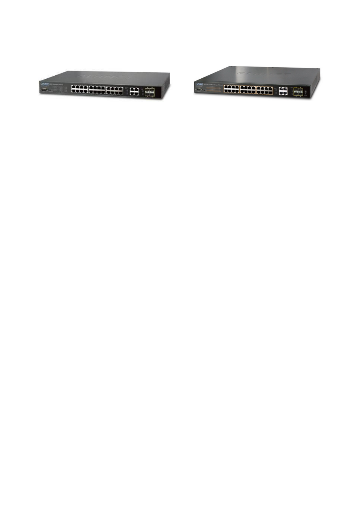
16
1.2 Product Description
User’s Manual of WGSW-28040 / 28040P / 28040P4
WGSW-28040 WGSW-28040P / WGSW-28040P4
Cost-effective IPv6 Managed Gigabit Switch solution for SMB
Nowadays, lots of electronic products or mobile devices can browse the Internet, which means the need of IP Addres s
increases. However, the current IPv4 network infrastructure is not capable enough to provide IP Address to each single
users/Clients. The situation forces the ISP to build up the IPv6 (Internet Protocol version 6) network infrastructure speedily.
To fulfill the demand, PLANET releases the IPv6 management Gigabit Ethernet Switch, WGSW-28040 series Managed
Switch. It supports both IPv4 and IPv6 management functions. It can work with original network structure (IPv4) and als o
support the new network structure (IPv6) in the future. With easy and fr ie ndly manag em ent interfaces and plenty of
management functions included, the WGSW-28040 series Managed Switch is the best choice for ISP to build the IPv 6 FTTx
edge service and for SMB to connect with IPv6 network.
High-Performance, Cost-effective Gigabit Networking Solution for SMB
The PLANET WGSW-28040 series is a Layer 2 Managed Gigabit Switch which can handle extremely large amounts of data
in a secure topology linking to an Enterprise backbone or high capacity network server with 56G bps switching fabric. The
advanced features of QoS and network security included enable the WGSW-28040 series to offer effective data traffic control
for SMB and Enterprises, such as VoIP, video streaming and multicast applicatio ns. It is ide al for the enter pr is e networks and
the aggregation layer of IP metropolitan networks.
High Performance
The WGSW-28040 series provides 28 10/100/1000Mbps Gigabit Ethernet ports in which with 4 shared Gigabit SFP slots. It
boasts high performance architecture of switch that is capable for providing the non-blocking switch fabric and wire-speed
throughput as high as 56Gbps, which greatly simplifies the tasks of upgrading the LAN for catering to increasing bandwidth
demands.
Robust Layer 2 Features
The WGSW-28040 series can be programmed for advanced switch management functions such as dynamic Port link
aggregation, Q-in-Q VLAN, private VLAN, Multiple Spanning Tree protocol, Layer 2 QoS, bandwidth control and IGMP
Snooping. The WGSW-28040 series provides 802.1Q Tagged VLAN, and the VLAN groups allowed will be maximally up to
255. Via aggregation of supporting ports, the WGSW-28040 series allows the operation of a high-speed trun k combini ng
multiple ports. It enables maximum up to 8 groups of 8 ports for trunking and supports fail-over as well.
Page 17

User’s Manual of WGSW-28040 / 28040P / 28040P4
17
Excellent Traffic Control
The WGSW-28040 series is loaded with Port speed configuration , Port aggre gat ion, VLAN, Sp anni ng Tree protocol, QoS,
bandwidth control and IGMP Snooping features to enhance services to business-class data, voice, security, and wireless
solutions. The functionality includes QoS features, and bandwidth limiting that are particular useful for multi-tenant unit and
multi-business unit applications. It also empowers the enterprise s t o take full advantages of the limited ne t w or k res our ces a nd
guarantees the best performance in VoIP and Video conferencing transmission.
Efficient Management
For efficient management, the WGSW-28040 series Managed Ethernet Switch is equippe d w it h console, WEB and SNMP
management interfaces. With the built-in Web-Based management interface, the WGSW-28040 series offers an easy-to-use,
platform-independent man age ment and con fig ur ati on faci lity. The WGSW-28040 supports standard Simple Network
Management Protocol (SNMP) and can be managed via any standard management software. For text-based management,
the WGSW-28040 series can be accessed via Telnet and the console port.
Powerful Security
PLANET WGSW-28040 series offers comprehensive Layer 2 to Layer 4 Access Contr ol List (ACL) for enforcing security to
the edge. It can be used to restrict network access by denying packets based on source and destination IP address,
TCP/UDP ports or defined typical network applications. Its protection mechanism also comprises of 802.1X port-based and
MAC-based user and device authentication. With the private VLAN function, communication between edge ports can be
prevented to ensure user privacy. The network administrators can now construct highly secured corporate networks with
considerably less time and effort than before.
Power over Ethernet, Easy Cabling Installation
The PoE in-line power follow ing the sta ndar d IEEE 802.3af makes the WGSW-28040P able to power on 24 PoE compliant
devices at the distance up to 100 meters thro ugh the 4-pair Cat 5/5e UTP wire. With data and power over Ethernet from one
unit, it can easily build a power central-controlled IP phone system, IP Camera system, or wireless AP group for the
enterprises. The WGSW-28040P shall reduce cables deployment and eliminates the need for dedicated electri ca l outlets on
the wall, ceiling or any unreachable place. A wire carries both data and power lowering the installation costs, simplifying the
installation effort and eliminating the need for electricians or extension cords.
Flexibility and Extension Solution
The four mini-GBIC slots built in the WGSW-28040 series are compatible with 1000Base-SX/LX and WDM SFP (Small Form
Factor Pluggable) fiber-optic modules. The distance can be extended from 550 meters (Multi-Mode fiber) up to above
10/20/30/40/50/70/120 kilometers (Single-Mode fiber or WDM fiber). It is well suited for a pplications within the enter pri se data
centers and distributions.
Page 18

User’s Manual of WGSW-28040 / 28040P / 28040P4
18
1.3 How to Use This Manual
This User Manual is structured as follows:
Section 2, INSTALLATION
The section explains the functi ons of the Switch and how to physically install the Managed Sw itch.
Section 3, SWITCH MANAGEMENT
The section contains the information about the software function of the Managed Switch.
Section 4, WEB CONFIGURATION
The section explains how to manage the Managed Switch by Web interface.
Section 5, COMMAND LINE INTERFACE
The section describes how to use the Command Line interface (CLI).
Section 6, CLI CONFIGURATION
The section explains how to manage the Managed Switch by Command Line interface.
Section 7, SWITCH OPERATION
The chapter explains how to does the switch operation of the Managed Switch.
Section 8, TROUBSHOOTING
The chapter explains how to trouble shooting of the Managed Switch.
Appendix A
The section contains cab le inf or mat ion of the Managed Switch.
1.4 Product Features
Physical Port
WGSW-28040
28-Port 10/100/1000Base-T Gigabit RJ-45 copper
4 100/1000Base-X mini-GBIC/SFP slots, shared with Port-25 to Port-28
RS-232 DB9 console interface fo r Switch basic management and setup
WGSW-28040P / WGSW-28040P4
28-Port 10/100/1000Base-T Gigabit RJ-45 copper with 24-Port IEEE 802.3af PoE Injector
4 100/1000Base-X mini-GBIC/SFP slots, shared with Port-25 to Port-28
RS-232 DB9 console interface fo r Switch basic management and setup
Layer 2 Features
Prevents packet loss with back pressure (Half-Duplex) and IEEE 802.3x PAUSE frame flow control (Full-Duplex)
High performance of Store-and-Forward architecture and runt/CRC filtering eliminates erroneous packets to optimize
the network bandwidth
Supports VLAN
− IEEE 802.1Q Tagged VLAN
− Up to 256 VLANs groups, out of 4094 VLAN IDs
− Provider Bri dging (VLAN Q-in-Q) support (IEEE 802.1ad)
Page 19

User’s Manual of WGSW-28040 / 28040P / 28040P4
19
− Private VLAN Edge (PVE / Port Isolation)
Supports Spanning Tree Protocol
− STP, IEEE 802.1D (Sp anning Tree Protocol)
− RSTP, IEEE 802.1w (Rapid Spanning Tree Protocol)
− MSTP, IEEE 802.1s Multiple Spanning Tree Protocol, spanning tree by VLAN
Supports Link Ag gregation
− IEEE 802.3ad Link Aggregation Control Protocol (LACP)
− Cisco ether-channel (Static Trunk)
− Maximum 8 trunk groups, up to 8 ports per trunk group
− Up to 16Gbps bandwidth (Duplex Mode)
Provide Port Mirror (many-to-1)
Port Mirroring to monitor the incoming or outgoing traffic on a particular port
Quality of Service
Ingress / Egress Rate Limit per port bandwidth control
8 priority queues on all switch ports
Traffic classification:
- Port-Based priority
- IEEE 802.1p CoS
- IP DSCP
Strict priority and Weighted Round Robin (WRR) CoS policies
DSCP remarking
Multicast
Supports IGMP Snooping v1, v2 and v3
Querier mode support
IGMP Snooping v2 fast leave
Unknown Multicast drop
Security
Storm Control support
− Broadcast / Multicast / Unknown-Unicast / Unknown-Multicast
Authentication
− IEEE 802.1X Port-Based network access authentication
− Built-in RADIUS client to co-operate with the RADIUS servers
Access Control List
− IP-Based ACL
− MAC-Based ACL
MAC Security
− Static MAC
Page 20

20
− Source / Destination MAC Filtering
− Port Security for Source MAC address entries filtering
Management
Switch Management Interfaces
- Console / Telnet Command Line Interface
- IPv4 and IPv6 Web switch management
- SNMP v1, v2c switch management
- SSH / SSL secure access
Four RMON groups (history, statistics, alarms, and events)
SNMP trap for interface Link Up and Link Down notification
SNTP (Simple Network Time Protocol)
Built-in Trivial File Transfer Protocol (TFTP) client
BOOTP and DHCP for IP address assignment
Firmware upload/download via HTTP / TFTP
User’s Manual of WGSW-28040 / 28040P / 28040P4
Event message logging to remote Syslog server
Reset button for system reboot or reset to factory default
Power over Ethernet (WGSW-28040P / WGSW-28040P4 Only)
■ Complies with IEEE 802.3af Power over Ethernet End-Span PSE
■ Up to 24 ports for IEEE 802.3af / at devices powered
■ Support PoE Power up to 15.4 watts for each PoE ports
■ Auto detect powered device (PD)
■ Circuit protection prevent power interference between ports
■ Remote power feeding up to 100m
■ PoE Management
■ Per port PoE function enable/disable
Page 21
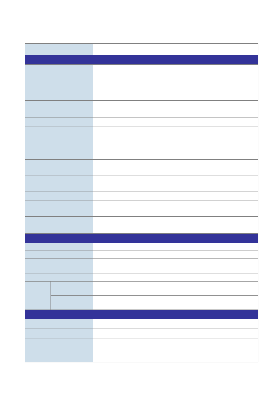
User’s Manual of WGSW-28040 / 28040P / 28040P4
21
Switch Processing Scheme
Store-and-Forward
Switch Fabric
56Gbps / non-blocking
Throughput @ 64Kbytes
41.67Mpps
MAC Address Table
16K entries
Share Data Buffer
448K bytes
Back pressure for Half-Duplex
Jumbo Frame
9216 Bytes
1000
LNK/ACT, 1000, PoE In-Use
Weight
2.7kg
3.9kg
4.3kg
BTU
BTU
Power Requirement
AC 100~240V, 50/60Hz
ESD Protection
6KV DC
PoE Standard
-
IEEE 802.3af PoE / PSE
PoE Power Supply Type
-
End-Span
PoE Power Output
-
Per Port 48V DC. Max. 15.4 watts
Power Pin Assignment
-
1/2(+), 3/6(-)
PoE Power Budget
-
180 Watts
380 Watts
7Watts
15.4Watts
Security Management Interfaces
Flow Control disable / enable
1.5 Product Specification
Product WGSW-28040 WGSW-28040P WGSW-28040P4
Hardware Specificati on
Copper Ports 28 10/ 100/1000Base-T RJ-45 Auto-MDI/MDI-X ports
SFP/mini-GBIC Slots
Flow Control
LED PWR, SYS, LNK/ACT,
Dimension (W x D x H)
Power Consumption Max. 12 Watts / 40.92 BTU
4 100/1000Base-X SFP interfaces, shared with Port-25 to Port-28
100Base-FX SFP transceiver compatible
IEEE 802.3x Pause Frame for Full-Duplex
440 x 200 x 44.5 mm, 1U
height
PWR, SYS, PWR Alert, FAN 1 & 2 Alert
440 x 300 x 44.5 mm, 1U height
Max. 202 Watts / 688.82
Max. 398 Watts / 1357.18
Power over Ethernet
Number of PD@
PoE Ability
Number of PD@
Layer 2 Function
Basic Management Interfaces Console, Telnet, IPv4 & IPv6 Web Browser, SNMPv1, v2c
Port Configuration
- 24 24
- 11 24
SSH, SSL
Port disable / enable
Auto-Negotiation 10/100/1000Mbps full and half duplex mode selection
Page 22
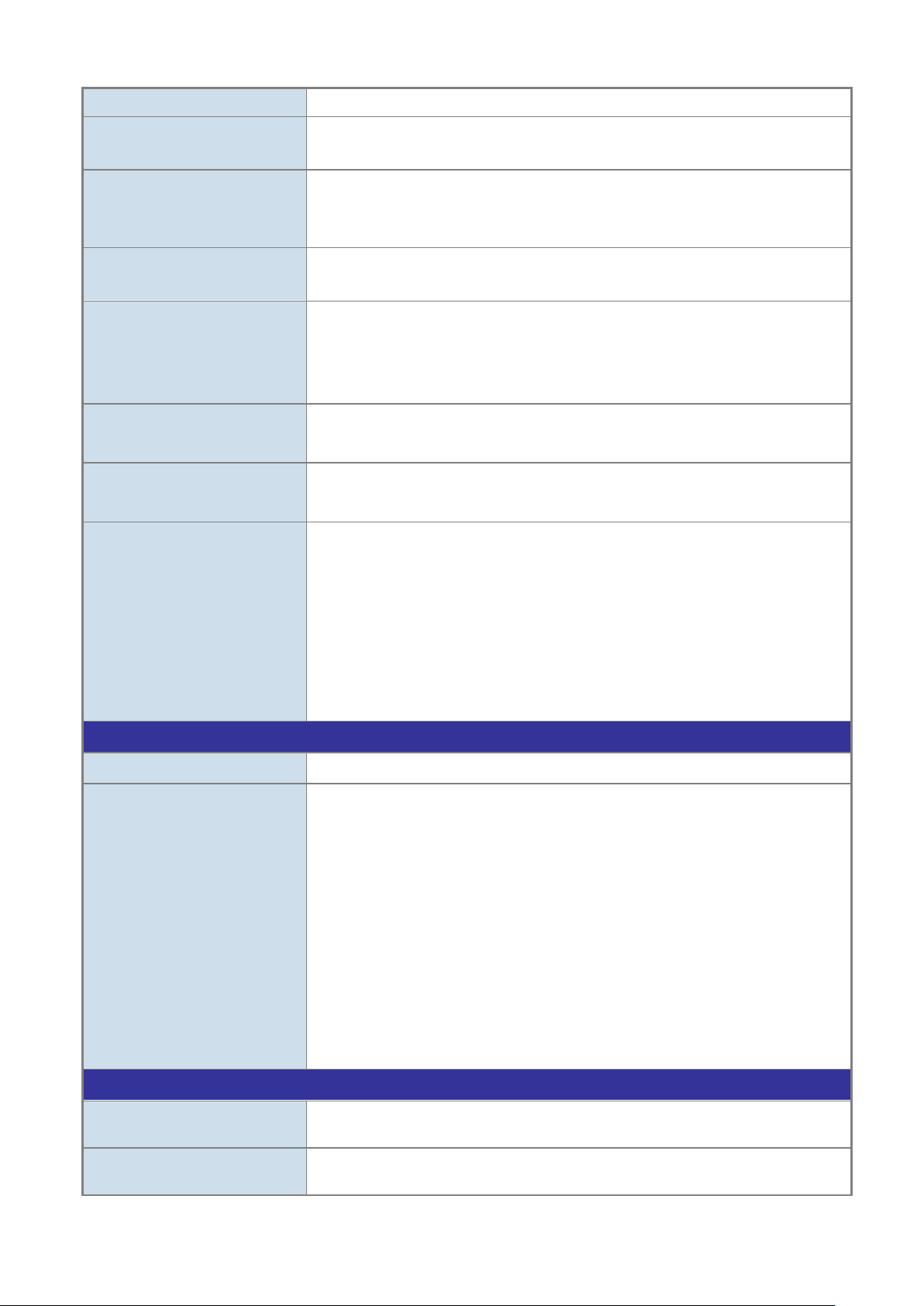
User’s Manual of WGSW-28040 / 28040P / 28040P4
22
Port Description
negotiation status, trunk status.
Up to 256 VLAN groups, out of 4094 VLAN IDs
8-Level priority queue for sw itc hing
RFC 3411 SNMP-MIB
IEEE 802.3af Power over Ethernet
Relative Humidity: 20 ~ 95% (non-condensing)
Relative Humidity: 20 ~ 95% (non-condensing)
Port Status
VLAN
Link Aggregation
QoS
IGMP Snooping
Access Control List
SNMP MIBs
Display each port’s speed duplex mode, link status, Flow control status, Auto
802.1Q Tagged Based VLAN
Q-in-Q
IEEE 802.3ad LACP / Static Trunk
Supports 8 group s of 8-Port tr unk suppor t
Traffic classification based, Strict priority and WRR
- 802.1p priority
- IP DSCP field
IGMP (v1/v2/v3) Snooping, up to 255 multicast Groups
IGMP Querier mode support
IP-Based ACL / MAC-Based ACL
Up to 256 entries
RFC 1213 MIB-II
IF-MIB
RFC 1493 Bridge MIB
RFC 1643 Ethernet MIB
RFC 2863 Interface MIB
RFC 2665 Ether-Like MIB
RFC 2819 RMON MIB (Group 1)
RFC 2737 Entity MIB
Standards Conformance
Regulation Compliance FCC Part 15 Class A, CE
IEEE 802.3 10Base-T
IEEE 802.3u 100Base-TX
IEEE 802.3z Gigabit SX/LX
IEEE 802.3ab Gigabit 1000T
IEEE 802.3x Flow Control
IEEE 802.3ad Port trunk with LACP
Standards Compliance
Environment
Operating
Storage
IEEE 802.1D Spanning tree protocol
IEEE 802.1w Rapid spanning tree protocol
IEEE 802.1s Multiple spanning tree protocol
IEEE 802.1p Class of service
IEEE 802.1Q VLAN Tagging
IEEE 802.1x Port Authentication Network Control
Temperature: 0 ~ 50 Degree C
Temperature: -10 ~ 70 Degree C
Page 23
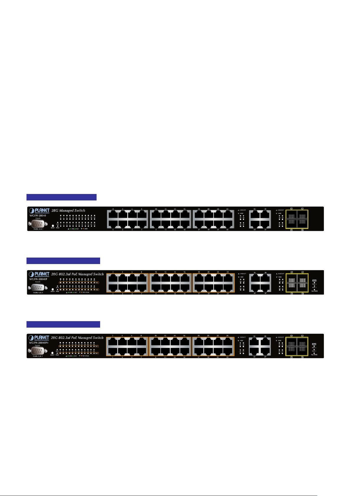
User’s Manual of WGSW-28040 / 28040P / 28040P4
23
2. INSTALLATION
This section describes the hardware features and installation of the Managed Switch on the desktop or rack mount. For easier
management and control of the Managed Switch, familiarize yourself with its display indicators, and ports. Front panel
illustrations in this chapter disp lay the unit LED i ndicator s. B efore c onnecti ng any netw ork de vice to the M anaged Sw itch, please
read this chapter completely.
2.1 Hardware Description
2.1.1 Switch Front Panel
The unit front panel provides a simple interface monitoring the switch. Figure 2-1, Figure 2-2 & Figure 2-3 shows the front panel
of the Managed Switch.
WGSW-28040 Front Panel
WGSW-28040P Front Panel
WGSW-28040P Front Panel
Figure 2-1 WGSW-28040 front panel
Figure 2-2 WGSW-28040P front panel
Figure 2-3 WGSW-28040P4 front panel
■ Gigabit TP Interface
10/100/1000Base-T Copper, RJ-45 Twist-Pair: Up to 100 meters.
■ 100/1000Base-X SFP Slots
Each of the SFP (Small Form-Factor Pluggable) slot supports Dual-Speed, 1000Base-SX / LX or 100Base-FX
- For 1000Base-SX/LX SFP transceiver module: F ro m 5 50 met er s (Multi-mode fiber), up to 10 /30/ 50 /70/ 120 kilometers
(Single-mode fiber).
Page 24
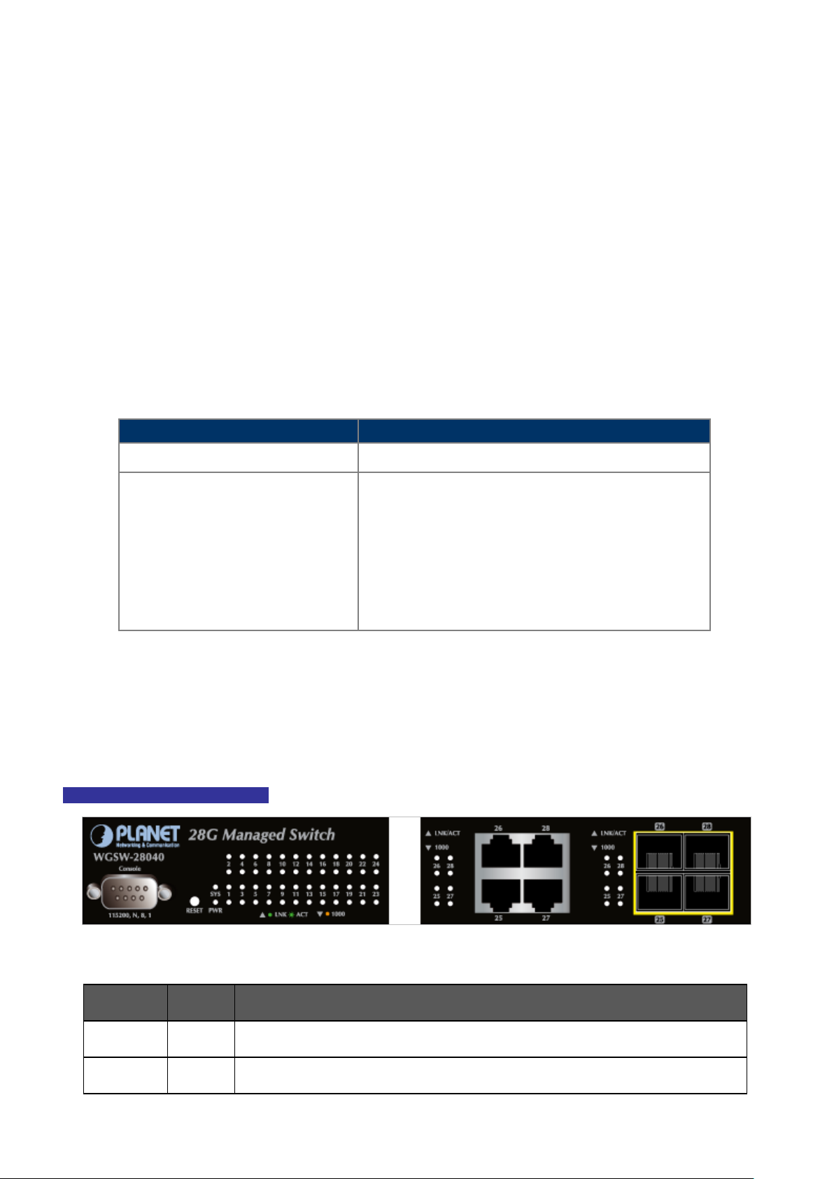
User’s Manual of WGSW-28040 / 28040P / 28040P4
24
Reset Button Pressed and Released
Function
Default Gateway: 192.168.0.254
Lights
Lights
- For 100Base-FX SFP transceiver module: From 2 kilometers (Multi-mode fiber), up to 20/40/60 kilometers
(Single-mode fiber).
■ Console Port
The console port is a DB9, RS-232 male serial port connector. It is an interface for connecting a terminal directly. Through
the console port, it provides rich diagnostic information includes IP Address setting, factory reset, port management, link
status and system sett ing. Users can use the atta che d R S -23 2 cab le i n the package and connect to t h e co ns ole p ort on the
device. After the connection, users an run any terminal emulation program (Hyper Terminal, ProComm Plus, Telix, Winterm
and so on) to enter the startup screen of the device.
■ ResetButton
At the left of front panel, the reset button is designed for reboot the Managed Switch without turn off and on the power. The
following is the summary table of Reset button functions:
< 5 sec: System reboot Reboot the Managed Switch
Reset the Managed Switch to Factory Default configuration.
The Managed Switch will then reboot and load the default
settings as below:
> 5 sec: Factory Default
。 Default Username: admin
。 Default Password: admin
。 Default IP address: 192.168.0.100
。 Subnet mask: 255.255.255.0
。
2.1.2 LED Indications
The front panel LEDs in dic ate s instant status of port links, data activit y and syst em power; helps monitor and tr oubl es hoot when
needed. Figure 2-4, Figure 2-5 & Figure 2-6 shows the LED i ndic atio ns of these Managed Switches.
WGSW-28040 LED indication
■ System
LED Color Function
PWR Green
SYS Green
Figure 2-4 WGSW-28040 LED panel
to indicate that the Switch has power.
to indicate the system is working.
Page 25
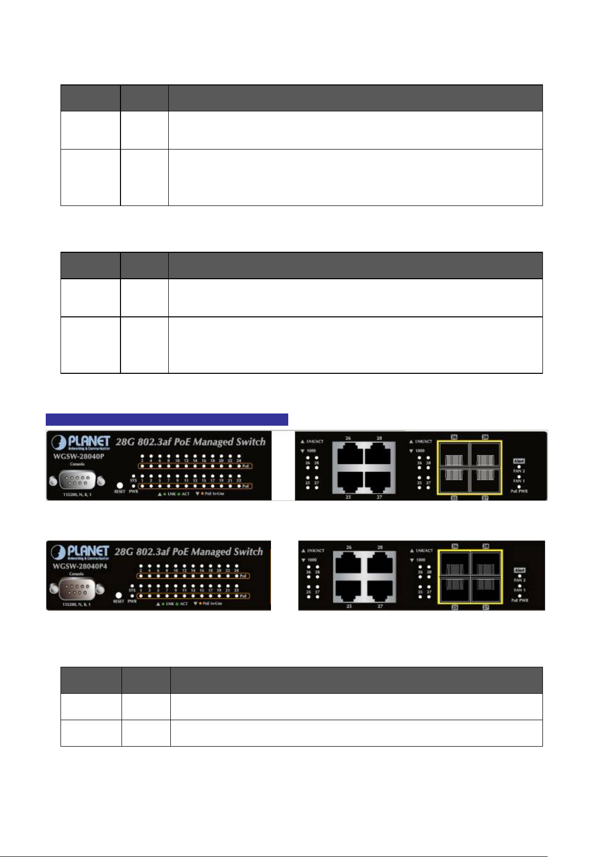
25
Lights
Lights
■ 10/100/1000Base-T interfaces
LED Color Function
User’s Manual of WGSW-28040 / 28040P / 28040P4
LNK/ACT Green
1000 Orange
■ 100 / 1000Base-X SFP interfaces (shared with Port-25 to Port-28)
LED Color Function
LNK/ACT Green
1000 Green
Lights: To indicate the link through that port is successfully established.
Blink: To indicate that the switch is actively sending or receiving data over that port.
Lights: indicate that the port is operating at 1000Mbps.
Off: If LNK/ACT LED light-> indicate that the port is operating at 10/100Mbps
If LNK/ACT LED Off -> ind ica te that the port is link down
Lights: To indicate the link through that port is successfully establish ed.
Blink: To indicate that the switch is actively sending or receiving data over that port.
Lights: indicate that the port is operating at 1000Mbps.
Off: If LNK/ACT LED light-> indicate that the port is operating at 100Mbps
If LNK/ACT LED Off -> ind ica te that the port is link down
WGSW-28040P / WGSW-28040P4 LED indication
Figure 2-5 WGSW-28040P LED panel
Figure 2-6 WGSW-28040P4 LED panel
■ System
LED Color Function
PWR Green
to indicate that the Switch has power.
SYS Green
to indicate the system is working.
Page 26
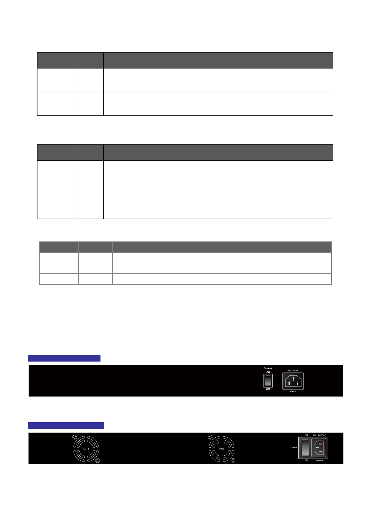
26
LED
Color
Function
PoE PWR
Green
Lights to indicate that the power supply failure
FAN1
Green
Lights to indicate that the FAN1 failure
FAN2
Green
Lights
■ 10/100/1000Base-T interfaces
LED Color Function
User’s Manual of WGSW-28040 / 28040P / 28040P4
LNK/ACT Green
PoE In-Use Orange
■ 1000Base-SX/LX SFP interfaces (shared with Port-25 to Port-28)
LED Color Function
LNK/ACT Green
1000 Green
■ Alert
Lights: To indicate the link through that port is successfully established.
Blink: To indicate that the switch is actively sending or receiving data over that port.
Lights: To indicate the port is providing 48VDC in-line power.
Off: To indicate the connected device is not a PoE Powered Device (PD)
Lights: To indicate the link through that port is successfully established.
Blink: To indicate that the switch is actively sending or receiving data over that port.
Lights: indicate that the port is oper ating at 1000Mbps.
Off: If LNK/ACT LED light-> indicate that the port is operating at 100Mbps
If LNK/ACT LED Off -> ind ica te that the port is link down
to indicate that the FAN2 failure
2.1.3 Switch Rear Panel
The rear panel of the Managed Switch indicates an AC inlet power socket, which accepts input power from 100 to 240V AC,
50-60Hz. Figure 2-6, Figure 2-7 & Figure 2-8 shows the rear panel of these Managed Switches
WGSW-28040 Rear Panel
Figure 2-6 Rear panel of WGSW-28040
WGSW-28040P Rear Panel
Figure 2-7 Rear panel of WGSW-28040P
Page 27

User’s Manual of WGSW-28040 / 28040P / 28040P4
27
not work till it is pow er ed. If y our ne t works should
Switch from
WGSW-28040P4 Rear Panel
Figure 2-8 Rear panel of WGSW-28040P4
■ AC Power Receptacle
For compatibility with electric service in most areas of the world, the Managed Switch’s power supply automatically adjusts
to line power in the range 100-240V AC and 50/60 Hz.
Plug the female end of the power cord firmly into the receptalbe on the rear panel of the Managed Switch. Plug the other
end of the power cord into an electric service outlet then the power will be ready.
The device is a pow er-r equire d dev ic e, i t means, it will
active all the time, please consider using UPS (Uninterrupted Power Supply) for your device. It will
Power Notice:
prevent you from network data loss or network downtime.
In some area, installing a surge suppression device may also help to protect your Managed
being damaged by unregulated surge or current to the Switch or the power adapter.
Page 28
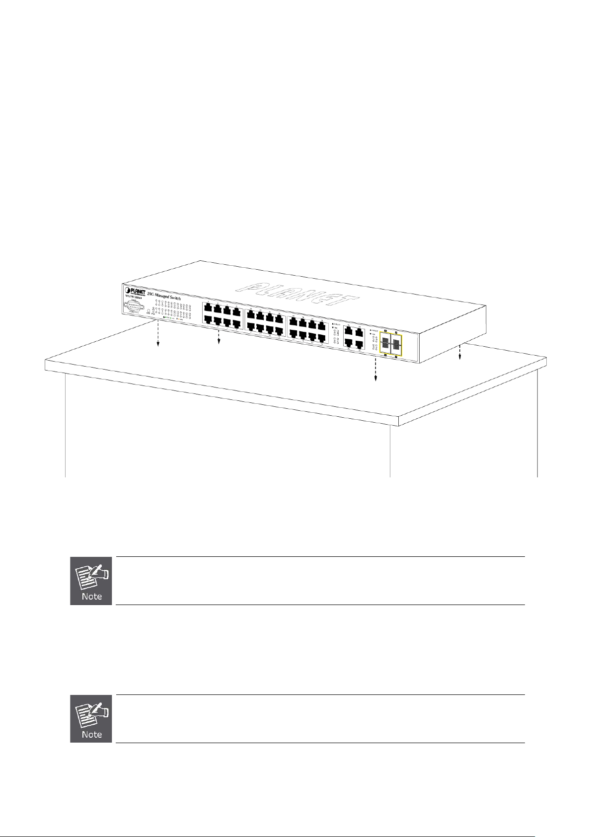
User’s Manual of WGSW-28040 / 28040P / 28040P4
28
When choosing a location, please keep in mind the environmental restrictions discussed in Chapter 1,
45 tips. For more
2.2 Install the Switch
This section describes how to install your Managed Switch and make connections to the Managed Switch. Please read the
following topics and perfor m th e proc edur e s i n the order being presented. To install your Managed Switch on a desktop or shelf,
simply complete the following step s.
2.2.1 Desktop Installation
To install the Managed S w itch on desktop or shelf, please follows these steps:
Step1: Attach the rubber feet to the recessed areas on the bottom of the Managed Switch.
Step2: Place the Managed Switch on the desktop or the shelf near an AC power source, as shown in Figure 2-9.
Figure 2-9 Place the Managed Switch on the desktop
Step3: Keep enough ventilation space between the Managed Switch and the surrounding objects.
Section 4, and Specification.
Step4: Connect the Managed Switch to network devices.
Connect one end of a standard network cable to the 10/100/1000 RJ-45 por ts on the front of the Managed Switch
Connect the other end of the cable to the network devices such as printer servers, workstations or routers…etc.
Connection to the Managed Switch requires UTP Category 5 network cabling with RJinformation, please see the Cabling Specification in Appendix A.
Page 29
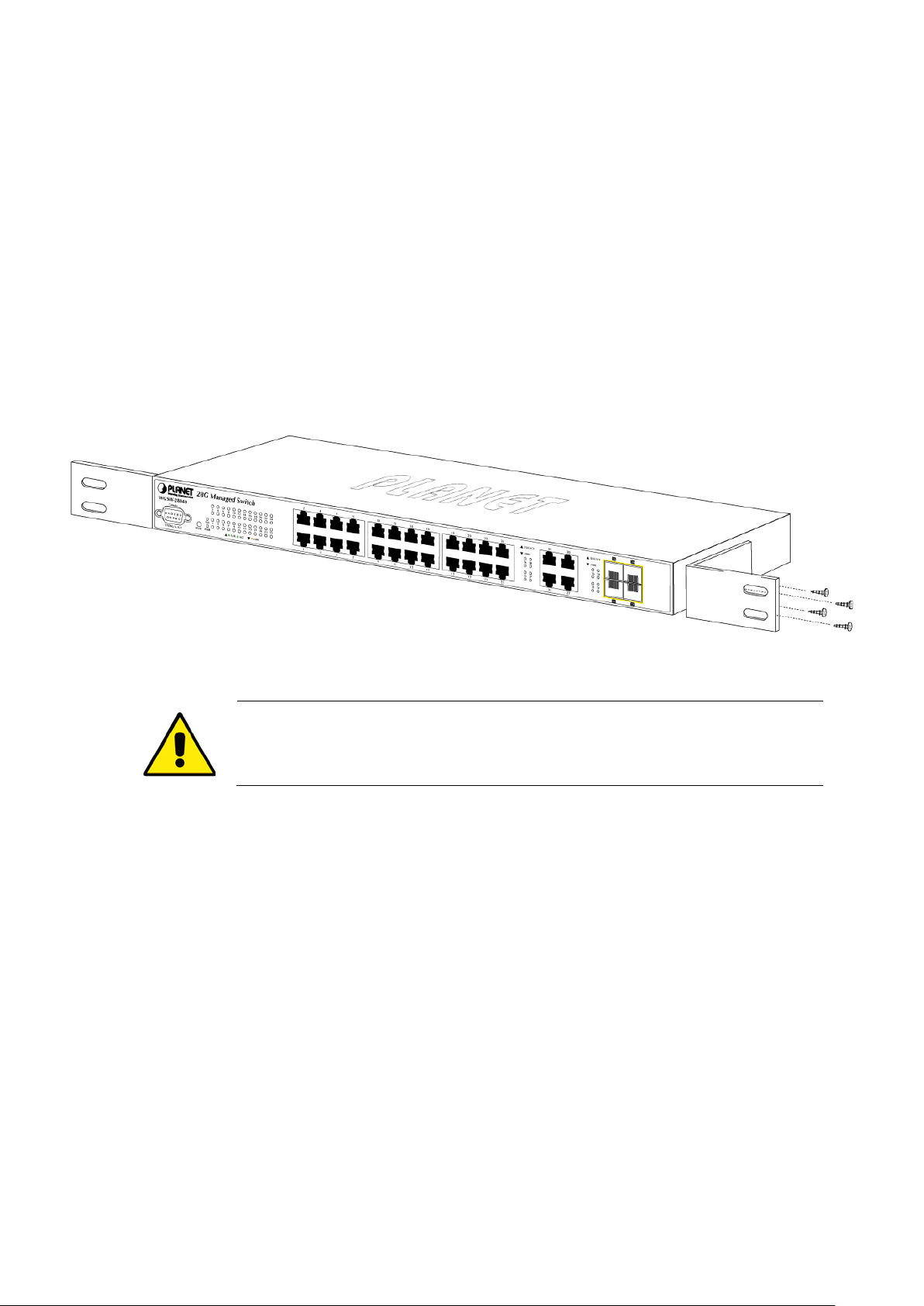
User’s Manual of WGSW-28040 / 28040P / 28040P4
29
the parts by
Step5: Supply power to the Managed Switch.
Connect one end of the power cable to the Managed Switch.
Connect the power plug of the power cable to a standard wall outlet.
When the Managed Switch receives power, the Power LED should remain solid Green.
2.2.2 Rack Mounting
To install the Managed S w itch in a 19-inch standard rack, please follows the instructions described below.
Step1: Place the Managed Switch on a hard flat surface, with the front panel positioned towards the front side.
Step2: Attach the rack-mount bracket to each side of the Managed Switch with supplied screws attached to the package.
Figure 2-10 shows how to attach brackets to one side of the Managed Switch.
Figure 2-10 Attach brackets to the Managed Switch
You mus t use the screws supplied with the mounting brackets. Damage caused to
using incorrect screws would invalidate the warranty.
Step3: Secure the brackets tightly.
Step4: Follow the same steps to attach the second bracket to the opposite side.
Step5: After the brackets are attached to the Managed Switch, use suitable screws to securely attach the brackets to the rack,
as shown in Figure 2-11.
Page 30
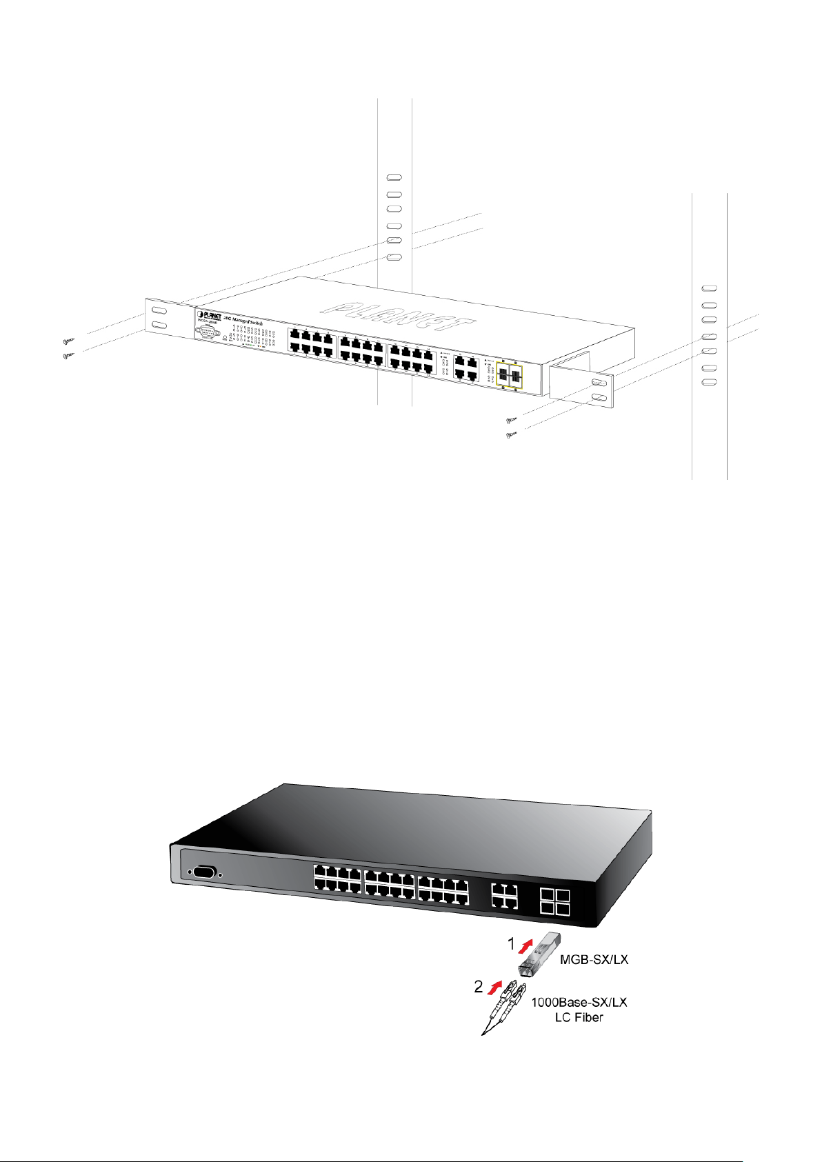
User’s Manual of WGSW-28040 / 28040P / 28040P4
30
Figure 2-11 Mounting Managed Switch in a Rack
Step6: Proceeds with the steps 4 and steps 5 of session 2.2.1 Desktop Installation to connect the network cabling and supply
power to the Managed Switch.
2.2.3 Installing the SFP transceiver
The sections describe how to insert an SFP transceiver into an SFP slot.
The SFP transceivers are hot-pluggable and hot-swappable. You can plug-in and out the transceiver to/from any SFP port
without having to power down the Managed Switch. As the Figure 2-12 appears.
Figure 2-12 Plug-in the SFP transceiver
Page 31

User’s Manual of WGSW-28040 / 28040P / 28040P4
31
Switch. If you insert a SFP transceiver that is
Approved PLANET SFP Transceivers
PLANET Managed Switch support s both 100Base-FX and 1000Base-SX/LX or Single mode and Multi-mode SFP transceiver.
The following list of approved PLANET SFP transceivers is correct at the time of publ icat io n:
Gigabit SFP Transceiver modules:
■ MGB-SX SFP (1000BASE-SX SFP transceiver / Multi-mode / 850nm / 220m or 550m)
■ MGB-LX SFP (1000BASE-LX SFP transceiver / Single mode / 1310nm / 10km)
■ MGB-L30 SFP (1000BASE-LX SFP transceiver / Single mode / 1310nm / 30km)
■ MGB-L50 SFP (1000BASE-LX SFP transceiver / Single mode / 1310nm / 50km)
■ MGB-LA10 SFP (1000BASE-LX SFP transceiver / WDM Single mode / TX: 1310nm, RX: 1550nm/ 10km)
■ MGB-LB10 SFP (1000BASE-LX SFP transceiver / WDM Single mode / TX: 1550nm, RX: 1310nm / 10km)
100Base-FX SFP Transceiver modules:
■ MFB-FX SFP (100BASE-FX SFP transceiver / Multi-mode / 1310nm / 2km)
■ MFB-F20 SFP (100BASE-FX SFP transceiver / Single mode / 1310nm / 20km)
■ MFB-FA20 SFP (100BASE-FX SFP transceiver / WDM Single mode / TX:1310nm, RX:1550nm / 20km)
■ MFB-FB20 SFP (100BASE-FX SFP transceiver / WDM Single mode / TX :1550nm, TX:1310nm / 20km)
It recommends using PLANET SFPs on the Managed
not supported, the Managed Switch will not recognize it.
Before connect the other Managed Switches, workst ation or Media Converter.
1. Make sure both side of the SFP transceiver are with the sa m e media typ e, for example: 1000Base-SX to 1000Base-SX,
1000Bas-LX to 1000Base-LX.
2. Check the fiber-optic cable type match the SFP transceiver model.
To connect to 1000Base-SX SFP transceiver, use the Multi-mode fiber cable- with one side must be male duplex LC
connector type.
To connect to 1000Base-LX SFP transceiver, use the Single-mode fiber cable-with one side must be male duplex LC
connector type.
Connect the fiber cable
1. Attach the duplex LC connector on the network cable into the SFP transceiver.
2. Connect the other end of the cable to a device – switches with SFP installed, fiber NIC on a workstation or a Media
Converter..
3. Check the LNK /ACT LED of the S FP slot on the fro nt of the Managed Switch. En sure that t he SFP tran sceiv er is oper ati ng
correctly.
4. Check the Link mode of the SFP port if the link failed. Co works with some fiber-NICs or Media Converters, set the Link
mode to “1000 Force” is needed.
Page 32

User’s Manual of WGSW-28040 / 28040P / 28040P4
32
Never pull out the module w ithout pull th e handle or the p ush bolt s on t he modul e. Dire ct pul l
Remo ve th e transceiver module
1. Make sure there is no network activity by consult or check with the network administrator. Or through the management
interface of the switch/converter (if available) to disable the port in advance.
2. Remove the Fiber Optic Cable gently.
3. Turn the handle of the MGB module to horizontal.
4. Pull out the module gently through the handle.
Figure 2-13 Pull out the SFP transceiver
out the module with violent could damage the module and SFP module slot of the Managed
Switch.
Page 33

User’s Manual of WGSW-28040 / 28040P / 28040P4
33
It is recom
3. SWITCH MANAGEMENT
This chapter explains the methods that you can use to configure management access to the Managed Switch. It describes the
types of management applications and the communication and management protocols that deliver data between your
management device (workstation or personal computer) and the system. It also contains information about port connection
options.
This chapter covers the following topics:
Requirements
Management Access Overview
Administration Console Access
Web Management Acce ss
SNMP Access
Standards, Protocols, and Related Reading
3.1 Requirements
Workstations of subscribers running Windows 98/ME, NT4.0, 2000/XP, MAC OS9 or later, Linux, UNIX or other
platform compatibl e with TCP/IP protocols.
Workstation installed with Ethernet NIC (Network Interface Card)
Serial Po rt connect (Terminal)
• Above PC with COM Port (DB9 / RS-232) or USB-to-RS-232 converter
Ethernet Port connect
• Network cables - Use standard network (UTP) cables with RJ45 connectors.
Above Workstation installed with WEB Browser and JAV A runtime environment Plug-in
mended to use Internet Explore 7.0 or above to access Managed Switch.
Page 34

User’s Manual of WGSW-28040 / 28040P / 28040P4
34
3.2 Management Access Overview
The Managed Switch gives you the flexibility to access and manage it using any or all of the following methods:
An administrat ion console
Web browser interface
An external SNMP-based network management application
The administration console and Web browser interface support are embedded in the Managed Switch software and are
available for immediate use. Each of these management methods has their own advantages. Table 3-1 compares the three
management methods.
Method Advantages Disadvantages
Console
Web Browser
SNMP Agent
• No IP address or subnet needed
• Text-based
• Telnet functionality and HyperTerminal
built into Windows
95/98/NT/2000/ME/XP operating
systems
• Secure
• Ideal for configuring the switch remotely
• Compatible with all popular browsers
• Can be accessed from any location
• Most visually appealing
• Communicates with switch fun ctio ns at
the MIB level
• Based on open standards
• Must be near switch or use dial-up connection
• Not convenient for remote users
• Modem connection may prove to be unreliable
or slow
• Security can be compromised ( hac kers need
only know the IP address and subnet mask)
• May encounter lag times on poor connections
• Requires SNMP manager software
• Least visually appealin g of all three methods
• Some settings require calculations
• Security can be compromised ( hac kers need
only know the community name)
Table 3-1 Management Methods Comparison
3.3 Administration Console
The administration console is an interna l, chara cter -oriented, and command line user interface for performing system
administration such as displaying statistics or changing option settings. Using this method, you can view the administration
console from a terminal, personal computer, Apple Macintosh, or workstation connected to the switch's console (serial) port.
There are two ways to use this management method: via direct access or modem port access. The following sections describe
these methods. For more information about using the console, refer to Chapter 5 Command Line Interface Console
Management.
Page 35

User’s Manual of WGSW-28040 / 28040P / 28040P4
35
Figure 3-1 Console management
Direct Access
Direct access to the administration console is achieved by directly connecting a terminal or a PC equipped with a
terminal-emulation program (such as HyperTerminal) to the Managed Switch console (serial) port.
When using this management method, a straight DB9 RS-232 cable is required to connect the switch to the PC. After
making this connection, configure the terminal-emulation program to use the following parameters:
The default parameters are:
115200 bps
8 data bits
No parity
1 stop bit
Figure 3-2 Terminal parameter settings
You can change these settings, if desired, after you log on. This management method is often preferred because you can
remain connected and monitor the system during system reboots. Also, certain error messages are sent to the serial port,
regardless of the interface through which the associated action was initiated. A Macintosh or PC attachment can use any
terminal-emulation progra m for connect ing to th e ter minal serial port . A workstation attachment und er UNIX can u se an em ulato r
such as TIP.
Page 36

User’s Manual of WGSW-28040 / 28040P / 28040P4
36
3.4 Web Management
The Managed Switch offers management features that allow users to manage the Managed Switch from anywhere on the
network through a sta ndard brow ser such as M icros oft Intern et Ex plorer. After you set up your IP ad dress for the sw itch, yo u can
access the Managed Switch's Web interface applications directly in your Web browser by entering the IP address of the
Managed Switch.
Figure 3-3 Web management
You can then use your Web browser to list and manage the Managed Switch configuration par amet er s from one central locati on ,
just as if you were directly connected to the Managed Switch's console port. Web Management requires either Microsoft
Internet Explorer 7.0 or later , Safari or Mozilla Firefox 1.5 or later.
Figure 3-4 Web main screen of Managed Switch
Page 37

User’s Manual of WGSW-28040 / 28040P / 28040P4
37
3.5 SNMP-Based Network Management
You can use an external SNMP-based application to configure and manage the Managed Switch, such as SNMPc Network
Manager, HP Openview Network Node Management (NNM) or What’s Up Gold. This management method requires the SNMP
agent on the switch and the SNMP Network Management Station to use the same community string. This management
method, in fact, uses two community strings: the get community string and the set community string. If the SNMP Net-work
management Station only knows the set community string, it can read and write to the MIBs. However, if it only knows the get
community string, it can only read MIBs. The default gets and sets community strings for the Managed Switch are public.
Figure 3-5 SNMP management
Page 38

User’s Manual of WGSW-28040 / 28040P / 28040P4
38
not allow Java Applets to open sockets. The user has to
4. WEB CONFIGURATION
This section introduces the configuration and functions of the Web-Based management.
About Web-based Management
The Managed Switch offers management features that allow users to manage the Managed Switch from anywhere on the
network through a standard browser such as Microsoft Internet Explorer.
The Web-Based Management supports Internet Explorer 7.0. It is based on Java Applets with an aim to reduce network
bandwidth consumption, enhance access speed and present an easy viewing screen.
By default, IE7.0 or later version does
explicitly modify the browser setting to enable Java Applets to use network ports.
The Managed Switch can be configured through an Ethernet connection, make sure the manager PC must be set on same the
IP subnet address with the Managed Switch.
For example, the default IP address of the SGSW Managed Switch is 192.168.0.100, then the manager PC should be set at
192.168.0.x (where x is a number between 1 and 254, except 100), and the default subnet mask is 255.255.255.0.
If you have changed the def aul t IP address of the Managed Switch to 192.168.1.1 with subnet mask 255.255. 255. 0 v ia co n sole ,
then the manager PC should be set at 192.168.1.x (where x is a number between 2 and 254) to do the relative configuration on
manager PC.
Figure 4-1-1 Web Management
Page 39

User’s Manual of WGSW-28040 / 28040P / 28040P4
39
Logging on the switch
1. Use Internet Explorer 7.0 or above Web browser. Enter the factory-default IP addres s to acces s the Web int erf ace . The
factory-default IP Address as following:
http://192.168.0.100
2. When the following login screen appears, please enter the default username "admin" with password “admin” (or the
username/password you have changed via console) to login the main screen of Managed Switch. The login screen in
Figure 4-1-2 appears.
Figure 4-1-2 Login screen
Default User name: admin
Default Password: admin
After entering the username and password, the main screen appears as Figure 4-1-3.
Page 40
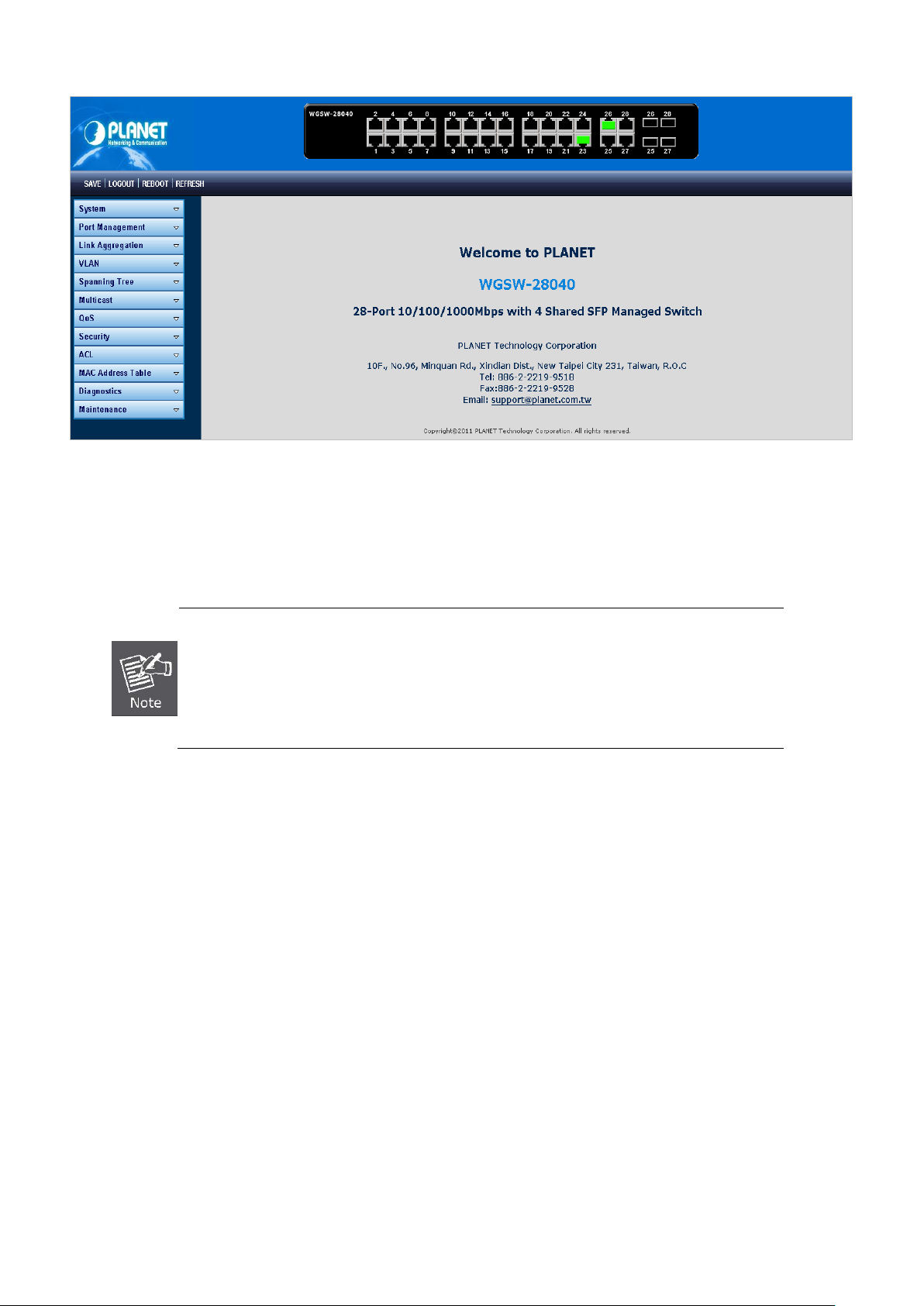
User’s Manual of WGSW-28040 / 28040P / 28040P4
40
button, you need to
Figure 4-1-3 Default main page
Now, you can use the Web management interface to continue the switch managemen t or manage the Managed Switch by Web
interface. The Switch Menu on the left of the web page let you access all the commands and statistics the Managed Switch
provides.
1. It is recommended to use Internet Explore 7.0 or above to access Managed Switch.
2. The changed IP address take effect immediately after click on the Save
use the new IP address to access the Web interface.
3. For security reason, please change and memorize the new password after this first setup.
4. Only accept command in lowercase letter under web interface.
Page 41

User’s Manual of WGSW-28040 / 28040P / 28040P4
41
4.1 Main Web Page
The Managed Switch provides a Web-based browser interface for configur ing and man agi n g it. This interface allows you to
access the Managed Switch using the Web browser of your choice. This chapter describes how to use the Managed Switch’s
Web browser interface to configure and manage it.
Main Functions Menu
Main Screen
Copper Port Link Status
SFP Port Link Status
Figure 4-1-4 Main Page
Panel Display
The web agent displays an image of the Managed Switch’s ports. T he M ode can be set to display different information for the
ports, including Link up or Link down. Clic kin g on the image o f a port opens the Port Statistics page.
The port states are illustrated as follows:
State Disabled Down Link
RJ-45 Ports
SFP Ports
Main Menu
Using the onboard web agent, you can define system par ame ter s, m ana ge an d con trol the Managed Switch, and al l its ports, or
monitor network conditions. Via the Web-Management, the administrator can setup the Managed Switch by select the functions
those listed in the Main Function. The screen in Figure 4-1-5 appears.
Page 42

User’s Manual of WGSW-28040 / 28040P / 28040P4
42
Figure 4-1-5 WGSW Managed Switch Main Functions Menu
Buttons
: Click to save changes or reset to default.
: Click to logout the Managed S witch.
: Click to reboot the Managed Switch.
: Click to refresh the page.
Page 43

User’s Manual of WGSW-28040 / 28040P / 28040P4
43
4.2 System
Use the System menu items to display and configure basic administrative details of the Managed Switch. Under System the
following topics are provided to configure and view the system information: This section has the following items:
■ System Information The switch system information is provided here.
■ IP Configuration Configure the switch-managed IP information on this page.
■ IPv6 Configuration
■ User Configuration
■ Enable Password Change the current password on this page.
■ SNTP Configuration Configure SNTP on this page.
■ Log Management The switch log information is provided here.
■ SNMP Management Configure SNMP on this page.
Configure the switch-managed IPv6 information on this page.
Configure new user name & password on this page.
Page 44

User’s Manual of WGSW-28040 / 28040P / 28040P4
44
4.2.1 System Information
The System Info page provides information for the current device informa tion. System Info page helps a switch administrator to
identify the hardware MAC address, software version and system uptime. The screen in Figure 4-2-1 & Figure 4-2-2 appears.
Figure 4-2-1 System Setting page screenshot
The page includes the following fields:
Object Description
• System Name
• System Location
• System Contact
Buttons
: Click to apply changes.
The system name configured on this field.
The system location configured on this field.
The system contact configured on this field.
Figure 4-2-2 System Information page screenshot
Page 45

45
The page includes the following fields:
Object Description
User’s Manual of WGSW-28040 / 28040P / 28040P4
• System Name
• System Location
• System Contact
• MAC Address
• IP Address
• Subnet Mask
• Gateway
• Loader Version
• Loader Date
• Hardware Version
• Firmware Version
• Firmware Date
Display the current system na me
Display the current system location
Display the current system con t a ct
The MAC Address of this Managed Switch.
The IP Address of this Managed Switch.
The subnet mask of this Managed Switch.
The gateway of this M anaged S witch.
The loader version of this Managed Switch.
The loader date of this Managed Switch.
The hardware version of this Managed Switch..
The firmware version of this Managed Switch.
The firmware date of this Managed Switch.
• System Object ID
The system object ID of the Managed Switch.
4.2.2 IP Configuration
The IP Configuration includes t he IP Ad dress, S ubnet M ask and Gatew ay. The Configured column is used to view or change t he
IP configuration. Fill up the IP Address, Subnet Mask and Gateway for the device. The screen in Figu re 4-2-3 & Figure 4-2-4
appears.
Figure 4-2-3 IP Address Setting page screenshot
Page 46

46
The page includes the following fields:
Object Description
User’s Manual of WGSW-28040 / 28040P / 28040P4
• Mode
• IP Address
• Subnet Mask
• Gateway
Indicates the IP addr es s mode operat ion . Possi ble mod es ar e:
Static: Enable NTP mode operation.
When enable NTP mode operation, the agent forward and to transfer NTP
messages between the clients and the server when they are not on the
same subnet domain.
DHCP: Enable DHCP client mode operation.
Enable the DHCP client by checking this box. If DHCP fails and the
configured IP address is zero, DHCP will retry. If DHCP fails and the
configured IP address is non-zero, DHCP will stop and the configured IP
settings will be used. The DHCP client will announce the configured
System Name as hostname to provide DNS lookup.
Provide the IP address of this switch in dotted decimal notation.
Provide the subnet mask of this switch dotted decimal notation.
Provide the IP address of the router in dotted decimal notation.
Buttons
: Click to apply changes.
The page includes the following fields:
Object Description
• DHCP State
• IP Address
Figure 4-2-4 IP Information page screenshot
Display the current DHCP state.
Display the current IP address .
• Subnet Mask
• Gateway
Display the current subnet mask.
Display the current gateway.
Page 47

User’s Manual of WGSW-28040 / 28040P / 28040P4
47
If fails, the configur ed IPv6 a ddr ess is zer o. T he rout er may delay respond ing to a
4.2.3 IPv6 Configuration
The IPv6 Configuration includes the Auto Configuration, IPv6 Address and Gateway. The Configured column is used to view or
change the IPv6 configuration. Fill up the Auto Configuration, IPv6 Address and Gateway for the device. The screen in Figure
4-2-5 & Figure 4-2-6 appears.
The page includes the following fields:
Object Description
• Auto Configuration
• IPv6 Address
Figure 4-2-5 IPv6 Address Setting page screenshot
Enable IPv6 auto-configuration by checking this box.
router solicitation for a few seconds, the total time needed to complete
auto-configuration can be significantly longer.
Provide the IPv6 address of this switch.
IPv6 address is in 128-bit records represented as eight fields of up to four
hexadecimal digits with a colon separates each field (:). For example,
'fe80::215:c5ff:fe03:4dc7'.
The symbol '::' is a special syntax that can be used as a shorthand way of
representing multiple 16-bit groups of contiguous zeros; but it can only appear
once. It also used a following legally IPv4 address. For example, '::192.1.2.34'.
Provide the IPv6 Prefix of this switch. The allowed range is 1 through 128.
• Gateway
Provide the IPv6 gateway address of this switch.
IPv6 address is in 128-bit records represented as eight fields of up to four
hexadecimal digits with a colon separates each field (:). For example,
'fe80::215:c5ff:fe03:4dc7'.
The symbol '::' is a special syntax that can be used as a shorthand way of
representing multiple 16-bit groups of contiguous zeros; but it can only appear
Page 48

User’s Manual of WGSW-28040 / 28040P / 28040P4
48
once. It also used a following legally IPv4 address. For example, '::192.1.2.34'.
• DHCPv6 Client
Buttons
: Click to apply changes.
Current IPv6 Information
To enable this Managed Switch to accept a configuration from a Dynamic Host
Configuration Protocol version 6 (DHCPv6) server. By default, the Managed
Switch does not perform DHCPv6 client actions. DHCPv6 clients request the
delegation of long-lived prefixes that they can push to individual local hosts.
The page includes the following fields:
Object Description
• Auto Configuration
• IPv6 Address
• IPv6 Gateway
• DHCPv6 Client
• DHCPv6 DUID
• DHCPv6 IP Address
DHCP Unique Identifier (DUID)—Each DHCPv6 component has a DUID (DHCPv6 Unique Identifier)
which is used to identify the device when exchanging DHCPv6 messages.
Figure 4-2-6 IPv6 Information page screen shot
Display the current auto configuratio n state.
Display the current IPv6 address
Display the current gateway
Displat the current DHCPv6 client status.
Displays the DUID information of the DHCPv6 client.
This information will be diplayed only after the DHCPv6 clisnet be enabled.
Displays the DHCPv6 IP Address of the DHCPv6 client.
This information will be diplayed only after the DHCPv6 clisnet be enabled.
Page 49

User’s Manual of WGSW-28040 / 28040P / 28040P4
49
Maximum number of users: 8
(Range: 0-30 characters plain text, case sensitive)
User
4.2.4 User Configuration
This page provides an overview of the current users and privilege type. Currently the only way to login as another user on the
web server is to close and reopen the browser. After setup completed, please press “Apply” button to take effect. Please login
web interface with new user name and password, the screen in Figure 4-2-7 & Figure 4-2-8 appears.
Figure 4-2-7 Local User Information page screenshot
The page includes the following fields:
Object Description
• Username
• Password Type
• Password
• Retype Password
• Privilege Type
Buttons
: Click to apply changes.
The name identifying the user.
Maximum length: 30 characters;
The password type for the user.
Enter the user’s new password here.
Please enter the user’s new password here again to confirm.
The privilgeg type for the user.
Options:
• Adminl
•
Figure 4-2-8 Local User page screenshot
Page 50

50
Encryption
The page includes the following fields:
Object Description
User’s Manual of WGSW-28040 / 28040P / 28040P4
• Username
• Password Type
• Privilege Type
• Modify
Display the current username.
Display the current password type.
Display the current privilege type.
Click to modify the local user entry.
: Delete the current user
4.2.5 Enable Password
This page provides to configure new password, the screen in Figure 4-2-9 appears.
Figure 4-2-9 Admin Enable Password page screenshot
The page includes the following fields:
Object Description
• Password Type
• Password
• Retype Password
Buttons
: Click to apply changes.
The password type for the user.
Options:
• Clear Text
•
Enter the user’s new password here.
Please enter the user’s new password here again to confirm.
Page 51

User’s Manual of WGSW-28040 / 28040P / 28040P4
51
4.2.6 SNTP Configuration
Configure SNTP on this page.
SNTP is an acronym for Simple Network Time P rot o col, a n etwork protocol for synchr oniz i ng the c loc ks of com puter systems.
You can specify SNTP Servers and set GMT Time zone. The SNTP Configuration screen in Figure 4-2-10 & Figure 4-2-11
appears.
The page includes the following fields:
Object Description
• Mode
• SNTP Server Address
• SNTP Server Port
• Time (HH:MM:SS)
• Date (YYYY-MM-DD)
Figure 4-2-10 SNTP Setup page screenshot
Indicates the SNTP mode operation. Possible modes are:
Enabled: Enable SNTP mode oper at ion.
When enable SNTP mode operation, the agent forward and to transfer
SNTP messages between the clients and the server when they are not
on the same subnet domain.
Disabled: Disable SNTP mode operation.
Type the IP address or domain name of the SNTP server.
Type the port number of the SNTP.
Click this option to set time manually.
Click this option to set date manually.
• Time Zone (+/- HH:MM)
Buttons
: Click to apply changes.
Allow select the time zone according to current location of switch.
Page 52

52
The page includes the following fields:
Object Description
User’s Manual of WGSW-28040 / 28040P / 28040P4
Figure 4-2-11 Time Information page screenshot
• SNTP State
• SNTP Server
• SNTP Port
• Current Time
• Current Date
• Time Zone
Display the current SNTP state.
Display the current SNTP server.
Display the current SNTP port.
Display the current time.
Display the current date.
Display the current time zone.
4.2.7 Log Management
The Managed Switch log management is provided here. The local logs er allows you to configure and limit system messages
that are logged to f la sh or R AM memory. The default is for event levels 0 to 3 t o be log ged to flash and levels 0 to 6 t o be logged
to RAM. The following table lists the event levels of the Managed Switch:
Level Severity Name Description
7 Debug Debugging messages
6 Informational Informational messages only
5 Notice Normal but significant condition, such as cold start
4 Warning Warning conditions (e.g., return false, unexpected return)
3 Error Error conditions (e.g., invalid input, default used)
2 Critical Critical conditions (e.g., memory allocation, or free memory
error - resource exhausted)
1 Alert Immediate action needed
0 Emergency System unusable
Page 53

User’s Manual of WGSW-28040 / 28040P / 28040P4
53
4.2.7.1 Local Log
The switch system local log information is provided here. The local Log screen in Figure 4-2-12 & Figure 4-2-13 appears.
Figure 4-2-12 Local Log Target Setting page screenshot
The page includes the following fields:
Buttons
Object Description
• Target
• Severity
: Click to apply changes.
The target of the local log entry. The following target types are supported:
RAM: Target the RAM of the local log.
Flash: Target the Flash of the local log.
The severuty of the local log entry. The following severity types are supported:
emerg: Emergency level of the system unsable for local log.
alert: Alert l ev el of the immediate action needed for local log.
crit: Critical level of the critical conditions for local log.
error: Error level of the error conditions for local log.
warning: Warning level of the warning conditions for local log.
notice: Notice level of the normal but significant conditions for local log.
info: Informational level of the informational messages for local log.
debug: Debug level of the debugging messages for local log.
Figure 4-2-13 Local Log Setting Status page screenshot
Page 54

54
The page includes the following fields:
Object Description
User’s Manual of WGSW-28040 / 28040P / 28040P4
• Status
• Target
• Severity
• Action
Display the current local log state
Display the current local log target
Display the current local log sever ity
Indicates the local log mode operation. Possible modes are:
Enabled: Enable local log mode operation.
When enable local log mode operation, the log and messages will be
recorded in the switch.
Disabled: Disable local log mode operation.
4.2.7.2 Remote Syslog
Configure remote syslog on this page. The Remote Syslog page allows you to configure the logging of messages that are sent
to syslog servers or other management stations. You can also limit the event messages sent to only those messages below a
specified level.
The Remote Syslog screen in Figure 4-2-14 & Figure 4-2-15 appears.
Figure 4-2-14 Remote Log Target page screenshot
Page 55

55
The page includes the following fields:
Object Description
User’s Manual of WGSW-28040 / 28040P / 28040P4
Buttons
• Server Index
• Server IP
• Server Port
• Severity
: Click to apply changes.
Select remote syslog server number for this drop down list.
Provide the remote syslog IP address of this switch.
Default Port no.: 514
Provide the port nimber of remote syslog server.
The severity of the local log entry. The following severity types are supported:
emerg: Emergency level of the system unsable for local log.
alert: Alert l ev el of the immediate action needed for local log.
crit: Critical level of the critical conditions for local log.
error: Error level of the error conditions for local log.
warning: Warning level of the warning conditions for local log.
notice: Notice level of the normal but significant conditions for local log.
info: Informational level of the informational messages for local log.
debug: Debug level of the debugging messages for local log.
Figure 4-2-15 Remote Log Setting Status page screenshot
The page includes the following fields:
Object Description
• Status
• Server Info
• Severity
• Action
Display the current remote syslog stat e
Display the current remote syslog server information
Display the current remote syslog severity
Indicates the remote syslog server mode operation. Possible modes are:
Enabled: Enable emote syslog server mode operation.
When enable remote syslog server mode operation, the log and
messages will be recorded to the remote syslog server.
Disabled: Disable re mote sysl og server mode operation.
Page 56

User’s Manual of WGSW-28040 / 28040P / 28040P4
56
4.2.7.3 Log View
The switch log view is provided here. The Log View screen in Figure 4-2-16, Figure 4-2-17 & Figure 4-2-18 appears.
Figure 4-2-16 Log Information Select page screenshot
The page includes the following fields:
Object Description
• Target
• Severity
• Category
The target of the log view entry. The following target types are supported:
RAM: Target the RAM of the log view .
Flash: Target the Flash of the log view.
The severity of the log view entry. The following severity types are supported:
emerg: Emergency level of the system unsable for log view.
alert: Alert l ev el of the immediate action needed for log view.
crit: Critical level of the critical conditions for log view.
error: Error level of the error conditions for log view.
warning: Warning level of the warning conditions for log view.
notice: Notice level of the nor mal but sig nifi can t cond itio ns for log view.
info: Informational level of the informational messages for log view.
debug: Debug level of the debugging messages for log view.
The category of the log view that are including:
ACL, Common, DAI, DEF_ENGINE, DoS, Dot1X, EEE, IGMP, L2, LACP, LLDP,
Log, Mirror, PoE, Port, QoS, QinQ , Rate, SNMP, STP, SVLAN, Switch, System,
TFTP, Trunk, UDLD, VLAN, LOOP_PROT
Buttons
: Click to view log.
Page 57

57
The page includes the following fields:
Object Description
User’s Manual of WGSW-28040 / 28040P / 28040P4
Figure 4-2-17 Log Information page screenshot
• Target
• Severity
• Categery
• Total Entries
Display the current log target.
Display the current log severity.
Display the current log categery
Display the current log entries
Figure 4-2-18 Logs page screenshot
The page includes the following fields:
Object Description
• No.
• Severity
• Categery
• Timestamp
• Message
Buttons
: Click to clear the log.
: Click to refresh the log.
This is the number for logs.
Display the severity type.
Display the category type.
Display the time of log.
Display the log message.
Page 58

User’s Manual of WGSW-28040 / 28040P / 28040P4
58
4.2.8 SNMP Management
4.2.8.1 SNMP Overview
The Simple Network Management Protocol (SNMP) is an appl icat ion layer pr oto col that facilitates the exchange of
management information betw een netw ork dev ices. It is p art of the Transmission Control Protocol/Internet Protocol (TCP/I P)
protocol suite. SNMP enables network administrators to manage network performance, find and solve network problems, and
plan for network growth.
An SNMP-managed network consists of three key components: Network management stations (NMSs), SNMP agents,
Management information base (MIB) and network-management protocol:
。 Network management stations (NMSs):Sometimes called consoles, these devices execute management applications
that monitor and control network elements. Physically, NMSs are usually engineering workstation-caliber computers with
fast CPUs, megapixel color displays, subst ant i al me mory, and abundant disk space. At lea s t one NMS must be present in
each managed environment.
。 Agents:Agents are software modules that reside in network elements. They collect and store management information
such as the number of error packets received by a network element.
。 Management information base (MIB):A MIB is a collection of managed objects residing in a virtual information store.
Collections of related managed objects are defined in specific MIB modules.
。 network-management protocol:A management protocol is used to convey management information between agents
and NMSs. SNMP is the Internet community's de facto standard management protocol.
SNMP Operations
SNMP itself is a simple request/response protocol. NMSs can send multiple requests without receiving a response.
。 Get -- Allows the NMS to retrieve an object instance from the agent.
。 Set -- Allows the NMS to set values for object instances within an agent.
。 Trap -- Used by the agent to asynchronously inform the NMS of some event. The SNMPv2 trap message is designed to
replace the SNMPv1 trap message.
SNMP community
An SNMP community is the group that devices and management stations running SNMP belong to. It helps define where
information is sent. The communit y name is used to identify the group. A SNMP device or agent may belong to more than one
SNMP community. It will not respond to requests from m anag ement st at ions th at do not bel o ng to one of its communities. S NMP
default communities are:
。 Write = private
。 Read = public
Page 59

User’s Manual of WGSW-28040 / 28040P / 28040P4
59
4.2.8.2 SNMP System Information
Configure SNMP setting on this page. The SNMP System global setting screen in Figure 4-2-19 & Figure 4-2-20 appears.
Figure 4-2-19 SNMP Global Setting page screenshot
The page includes the following fields:
Object Description
• Status
Buttons
: Click to apply changes.
The page includes the following fields:
Indicates the SNMP mode operation. Possible modes are:
Enabled: Enable SNMP mode operation.
Disabled: Disable SNMP mode operation.
Figure 4-2-20 SNMP Informations page screenshot
Object Description
• SNMP
Display the current SNMP status
Page 60

User’s Manual of WGSW-28040 / 28040P / 28040P4
60
4.2.8.3 SNMP View Table
Configure SNMPv3 view table on this page. The entry index keys are View Name and OID Subtree. The SNMPv3 View Table
Setting screen in Figure 4-2-21 and Figure 4-2-22 appears.
Figure 4-2-21 SNMPv3 View Table Setting page screen shot
The page includes the following fields:
Buttons
Object Description
• View Name
• Subtree OID
• Subtree OID Mask
• View Type
: Click to add a new view entry.
A string identifying the view name that this entry should belong to.
The allowed string length is 1 to 16.
The OID defining the root of the subtree to add to the named view.
The allowed string content is digital number or asterisk(*).
The bitmask identifies which positions in the specified object identifier are to be
regarded as "wildcards" for the purpose of pattern-matching.
Indicates the view type that this entry should belong to. Possible view type are:
included: An optional flag to indicate that this view subtree should be included.
excluded: An optional flag to indicate that this view subtree should be excluded.
General, if a view entry's view type is 'excluded', it should be exist another view
entry which view type is 'included' and it's OID subtree overstep the 'excluded'
view entry.
Figure 4-2-22 SNMP view Table Status page screenshot
Page 61

User’s Manual of WGSW-28040 / 28040P / 28040P4
61
4.2.8.4 SNMP Access Group
Configure SNMPv3 access group on this page. The entry index keys are Group Name, Security Model and Security Level.
The SNMPv3 Access Group Setting screen in Figure 4-2-23 appears.
Figure 4-2-23 SNMPv3 Access Group Setting page screenshot
The page includes the following fields:
Object Description
• Group Name
• Security Model
• Security Level
A string identifying the group name that this entry should belong to.
The allowed string length is 1 to 16.
Indicates the security model that this entry should belong to.
Possible security models are:
v1: Reserved for SNMPv1.
v2c: Reserved for SNMPv2c.
V3: Reserved for SNMPv3 or User-based Security Model (USM)
Indicates the security model that this entry should belong to.
Possible security models are:
Noauth: None authentication and none privacy security levels are assigned
to the group.
auth: Authentication and none privacy.
priv: Authentication and privacy.
Note: The Security Level applies to SNNPv3 only.
• Read View Name
The name of the MIB view defining the MIB objects for which this request may
Page 62

User’s Manual of WGSW-28040 / 28040P / 28040P4
62
request the current values.
The allowed string length is 1 to 16.
• Write View Name
Buttons
: Click to add a new access entry.
: Check to delete the entry.
The name of the MIB view defining the MIB objects for which this request may
potentially SET new values.
The allowed string length is 1 to 16.
4.2.8.5 SNMP Community
Configure SNMP Community on this page. The SNMP Community screen in Figure 4-2-24 & Figure 4-2-25 appears.
The page includes the following fields:
Object Description
• Community Name
• Group Name
• View Name
• Access Right
Figure 4-2-24 Community Setting page screenshot
Indicates the community read/write access string to permit access to SNMP
agent.
The allowed string length is 0 to 16.
A string identifying the group name that this entry should belong to.
The allowed string length is 1 to 16.
A string identifying the view name that this entry should belong to.
The allowed string length is 1 to 16.
Indicates the SNMP community type operation. Possible types are:
RO=Read-Only: Set access string type in r ead-only mode.
RW=Read-Write: Set access string type in read-write mode.
Page 63

63
Buttons
: Click to apply changes.
The page includes the following fields:
User’s Manual of WGSW-28040 / 28040P / 28040P4
Figure 4-2-25 Community Status page screenshot
Object Description
• Community Name
• Group Name
• Access Right
• Delete
Display the current community type.
Display the current SNMP access group’s name.
Display the current access type.
Click to delete the community entry.
4.2.8.6 SNMP User
Configure SNMPv3 users table on this page. Each SN MPv3 user is defined by a unique na me. U ser s m ust b e co nfig ured with a
specific security level and assigned to a group. The SNMPv3 group restricts users to a specific read, write, and notify view. The
entry index key is User Name. The SNMPv3 User Setting screen in Figure 4-2-26 appears.
Figure 4-2-26 SNMPv3 Users Configuration page screenshot
Page 64

64
The page includes the following fields:
Object Description
User’s Manual of WGSW-28040 / 28040P / 28040P4
• User Name
• Group
• Priviledge Mode
• Authentication
Protocol
A string identifying the user name that this entry should belong to.
The allowed string length is 1 to 16.
The SNMP Access Group. A string identifying the group name that this entry
should belong to.
Indicates the security model that this entry should belong to. Possible security
models are:
NoAuth: None authenticat ion and none priv acy.
Auth: Authentication and none privacy.
Priv: Authentication and privacy.
The value of security level cannot be modified if entry already exist. That means
must first ensure that the value is set correctly.
Indicates the authentication protocol that this entry should belong to. Possible
authentication protocol are:
None: None authentication protocol.
MD5: An optional flag to indicate that this user using MD5 authentication
protocol.
SHA: An optional flag to indicate that this user using SHA authentication
Buttons
• Authentication
Password
• Encryption Protocol
• Encryption Key
: Click to add a new user entry.
protocol.
The value of security level cannot be modified if entry already exist. That means
must first ensure that the value is set correctly.
A string identifying the authentication pass phrase. For both MD5 and SHA
authentication protocol, the allowed string length is 8 to 16.
Indicates the privacy protocol that this entry should belong to. Possible privacy
protocol are:
None: None privacy protocol.
DES: An optional flag to indicate that this user using DES authentication
protocol.
A string identifying the privacy p as s phrase .
The allowed string length is 8 to 16.
: Check to delete the entry.
Page 65

User’s Manual of WGSW-28040 / 28040P / 28040P4
65
4.2.8.7 SNMP Engine ID
Configure SNMPv3 Engine ID on this page. The entry index key are Engine ID. The remote engine ID is used to compute the
security digest for authenticating and encrypting packets sent to a user on the remote host. The SNMPv3 Engine ID Setting
screen in Figure 4-2-27 appears.
Figure 4-2-27 SNMPv3 Engine ID Setting page screenshot
The page includes the following fields:
Object Description
• Engine ID
An octet string identifying the engine ID that this entry should belong to. The
string must contain an even number betw een 5 and 32 hexadecimal digits, but
all-zeros and all-'F's are not allowed.
4.2.8.8 SNMP Trap Host
Configure SNMP trap on this page. The SNMP Trap Configuration screen in Figure 4-2-28 & Figure 4-2-29 appears.
Page 66
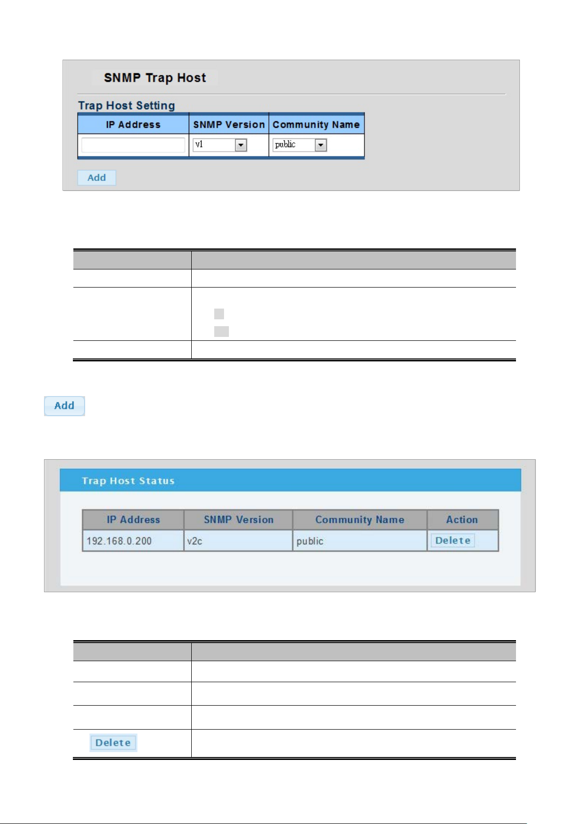
66
Figure 4-2-28 Trap Receiver Setting page scre ens hot
The page includes the following fields:
Object Description
User’s Manual of WGSW-28040 / 28040P / 28040P4
• IP Address
• SNMP Version
• Community Name
Buttons
: Click to add a new user entry.
SNMP Trap Host Status
Indicates the SNMP trap destination address.
Indicates the SNMP trap supported version. Possible versions are:
v1: Set SNMP trap supported SNMP version 1.
v2c: Set SNMP trap supported SNMP version 2c.
Indicates the community access string when send SNMP trap packet.
Figure 4-2-29 Trap Receiver Status page screenshot
The page includes the following fields:
Object Description
• IP Address
• SNMP Version
• Community Name
•
Display the current SNMP trap destination address.
Display the current SNMP version.
Display the current community name.
Click to delete the SNMP trap server entry.
Page 67

User’s Manual of WGSW-28040 / 28040P / 28040P4
67
4.3 Port Management
Use the Port Menu to display or configure the Managed Switch's ports. This section has the following items:
Port Configuration Configures port configuration settings
Port Counters Lists Ethernet and RMON port statistics
Port Error Disab led Disable port error status
Port Mirroring Sets the source and target ports for mirroring
Jumbo Frame Set the jumbo frame on the switch
Protected Ports Configuration protected ports settings
Bandwidth Control Configures bandwidth control settings
4.3.1 Port Configuration
This page displays current port configurations and status. Ports can also be configured here. The port settings relate to the
currently selected stack unit, as reflected by the page header. The table has one row for each port on the selected switch in the
stack and a number of colu mn s, which are:
The Port Configuration screen in Figure 4-3-1 & Figure 4-3-2 appears.
Figure 4-3-1 Port Settings page screenshot
The page includes the following fields:
Object Description
• Port Select
• Name
• Enabled
• Speed
Select port number for this drop down list.
Indicates the per port name.
Indicates the port state operation. Possible state are:
Enabled - Start up the port manually.
Disabled - Shutdown the port manually.
Select any available link speed for the given switch port. Draw the menu bar to
select the mode.
Page 68

User’s Manual of WGSW-28040 / 28040P / 28040P4
68
Auto - Setup Auto negotiation.
Auto-10M - Setup 10M Auto negotiation.
Auto-100M - Setup 100M Auto negotiation.
Auto-1000M - Setup 1000M Auto negotiation.
Auto-10/100M - Setup 10/100M Auto negotiation.
10M - Setup 10M Force mode.
100M - Setup 100M Force mode.
1000M - Setup 1000M Force mode.
Buttons
• Duplex
• Flow Control
: Click to apply changes.
Select any available link duplex for the given switch port. Draw the menu bar to
select the mode.
Auto - Setup Auto negotiation.
Full - Force sets Full-Duplex mode.
Half - Force sets Half-Duplex mode.
When Auto Speed is selected for a port, this section indicates the flow control
capability that is advertised to the link partner.
When a fixed-speed setting is selected, that is what is used.
Current Rx column indicates whether pause frames on the port are obeyed.
Current Tx column indicates whether pause frames on the port are transmitted.
The Rx and Tx settings are determined by the result of the last Auto-Negotiation.
Check the configured column to use flow control.
This setting is related to the setting for Configured Link Speed.
Port Statu s
Figure 4-3-2 Port Status page screenshot
Page 69

69
The page includes the following fields:
Object Description
User’s Manual of WGSW-28040 / 28040P / 28040P4
• Port
• Name
• Enable State
• Link Status
• Speed
• Duplex
• Flow Control
Configuration
• Flow Control Status
This is the logical port number for this row.
Display the current port name of the port.
Display the current port state.
Display the current link sta tus .
Display the current speed status of the port.
Display the current duplex status of the port.
Display the current flow control configuration of the port.
Display the current flow control status of the port.
4.3.2 Port Statistics
This page provides an overview of traffic and trunk statistics for all switch ports. The Port Statistics screen in Figure 4-3-3 &
Figure 4-3-4 appears.
Figure 4-3-3 Port Statistic page screenshot
The displayed counters are:
Object Description
• Port
• Link Status
• Tx Good Packets
The logical port for the settings contained in the same row.
Display the current link status of the port.
The number of transmitted good packets per port.
Page 70

User’s Manual of WGSW-28040 / 28040P / 28040P4
70
• Tx Bad Packets
• Rx Good Packets
• Rx Bad Packets
Buttons
: Clears the counters for all ports.
: Click to refresh the page immediately.
Port Statistic
The number of frames transmitted in error and the number of incomplete
transmissions per port.
The number of received good packets per port.
The number of frames received in error and the number of incomplete
transmissions per port.
The displayed counters are:
Object Description
• Trunk
• Tx Good Packets
• Tx Bad Packets
• Rx Good Packets
• Rx Bad Packets
Figure 4-3-4 Trunk Statistic page screenshot
This is the number for trunk entry.
The number of transmitted good packets per trunk.
The number of frames transmitted in error and the number of incomplete
transmissions per trunk.
The number of received good packets per trunk.
The number of frames received in error and the number of incomplete
transmissions per trunk.
Page 71

User’s Manual of WGSW-28040 / 28040P / 28040P4
71
RMON
4.3.3 Port Counters
This page provides detailed traffic statistics for a specific switch port. Use the port select box to select which switch port details
to display. The selected port belong to t he currently selected st a ck un it, as reflected by the page header. The displayed counters
are the totals for rec eiv e a nd transmit, the size cou nter s for receive and transmi t, and the error counters f or r e ceiv e and t ransmit.
The Port Counters screen in Figure 4-3-5 & Figure 4-3-6 appears.
Figure 4-3-5 Port Counters Settings page screenshot
The displayed counters are:
Object Description
• Port
• Mode
Port Counters Mode
Select port number for this drop down list.
Select port counters mode.
Option:
All
Interface
Ether-like
Page 72

User’s Manual of WGSW-28040 / 28040P / 28040P4
72
Figure 4-3-6 Counters page s creen sho t
Interface Counters:
Object Description
• Received Octets
• Received Unicast
Packets
The total number of octets received on the interface, including framing
characters.
The number of subnetwork-unicast packets delivered to a higher-layer protocol.
Page 73

User’s Manual of WGSW-28040 / 28040P / 28040P4
73
The number of inbound packets which were chosen to be discarded even though
The number of inbound packets which were chosen to be discarded even though
A count of frames re ceived o n a p arti cular inter fac e that ar e an integr al numbe r of
A count of frames for which the first transmission attempt on a particularinterface
• Received Nuknown
Unicast Packets
• Received Discards
Packets
• Transmit Octets
• Transmit Unicast
Packets
• Transmit Nuknown
Unicast Packets
• Transmit Discards
Packets
The number of packets received via the interface which were discarded because
of an unknown or unsupported protocol.
no errors had been detected to prevent their being deliverable to a higher-layer
protocol. One possible reason for discarding such a packet could be to free up
buffer space.
The total number of octets transmitted out of the interface, including framing
characters.
The total number of packets that higher-level protocols requested be transmitted
to a subnetwork-unicast addr ess, i ncluding those that w ere discar ded or not sent .
The total number of packets that higher-level protocols requested betransmitted
to a subnetwork-unicast addr ess, i ncluding those that w ere discar ded or not sent .
no errors had been detected to prevent their being deliverable to ahigher-layer
protocol. One possible reason for discarding such a packet could be to free up
buffer space.
• Received Multicast
Packets
• Received Broadcast
Packets
• Transmit Multicast
Packets
• Transmit Broadcast
Packets
Ethernet-Link Counters:
Object Description
• Alignment Errors
• FCS Errors
The number of packets, delivered by this sub-layer to a higher (sub-)layer, which
were addressed to a multicast address at this sub-layer.
The number of packets, delivered by this sub-layer to a higher (sub-)layer, which
were addressed to a broadcast address at this sub-layer.
The total number of packets that higher-level protocols requested betransmitted,
and which were addressed to a multicast address at this sub-layer, including
those that were discarded or not sent.
The total number of packets that higher-level protocols requested be transmitted,
and which were addressed to a broadcast address at this sub-layer, including
those that were discarded or not sent.
The number of alignment err or s (mis sy nchro niz ed dat a p ackets).
octets in length but do not pass the FCS check. This count does not include
frames received with frame-too-long or frame-too-short error.
• Single Collision
Frames
• Multiple Collision
Frames
• Deferred
The number of successfully transmitted frames for which transmission isinhibited
by exactly one collision.
A count of successfully transmitted frames for which transmission is inhibited by
more than one collision.
Page 74

User’s Manual of WGSW-28040 / 28040P / 28040P4
74
The total number of frames received that were longer than 1518 octets(excluding
Transmissions is delayed because the medium was busy.
• Late Collision
• Excessive Collision
• Frame Too Longs
• Symbol Errors
• Control In Unknow
Opcodes
• In Pause Frames
• Out Pause Frames
RMON Counters:
Object Description
The number of times that a collision is detected later than 512 bit-tim es into the
transmission of a packet.
A count of frames for which transmission on a particular interface fails due to
excessive collisions. This counter does not increment when the interface is
operating in full-duplex mode.
A count of frames received on a particular interface that exceed the maximum
permitted frame size.
The number of received and transmitted symbol errors.
The number of received control unknown opcodes
The number of received pause frames
The number of transmitted pause frames
• Drop Events
• Octets
• Packets
• Broadcast Packets
• Multicast Packets
• CRC / Alignment
Errors
• Undersize Packets
• Oversize Packets
• Fragments
The total number of events in which packets were dropped due to lack of
resources.
The total number of octets received and transmitted on the interface, including
framing characters.
The total number of packets received and transmitted on the interface.
The total number of good frames received that were directed to the broadca st
address. Note that this does not include multicast packets.
The total number of good frames received that were directed to this multicast
address.
The number of CRC/alignment errors (FCS or alignment errors).
The total number of fra me s rec eiv ed that were less than 64 octet s lon g( excluding
framing bits, but including FCS octets) and were otherwise well formed.
The total number of frames received that were longer than 1518 octets(excluding
framing bits, but including FCS octets) and were otherwise well formed.
The total number of frames received that were less than 64 octets in length
(excluding framing bits, but including FCS octets) and had either an FCS or
alignment error.
• Jabbers
framing bits, but including FCS octets), and had either an FCS or alignm ent error.
Page 75

User’s Manual of WGSW-28040 / 28040P / 28040P4
75
• Collisions
• 64 Bytes Frames
• 65-127 Byte Frames
128-255 Byte Frames
256-511 Byte Frames
512-1023 Byte Frames
1024-1518 Byte
Frames
• Lack Packets Buffer
Drop
The best estimate of the total number of collisio ns on this Et hernet se gment .
The total number of frames (including bad packets) received andtransmitted that
were 64 octets in length (excluding framing bits but including FCS octets).
The total number of frames (including bad packets) received andtransmitted
where the number of octets fall within the specified range (excluding framing bits
but including FCS octets).
The number of Lack Packets Buffer Drop
4.3.4 Port Error Disabled
This page provides disable that transitions a port into error disable and the recovery options. The ports were disabled by some
protocols such as BPDU Guard, Loopback and UDLD. The Port Error Disable screen in Figure 4-3-7 appears.
Figure 4-3-7 Port Error Disable page screenshot
The displayed counters are:
Object Description
• Port Name
• Error Disable Reason
Buttons
Display the port for error disable.
Display the error disabled reason of the port.
: Click to recover port error status.
Page 76

User’s Manual of WGSW-28040 / 28040P / 28040P4
76
4.3.5 Port Mirroring
Configure port Mirroring on this page. This function provide to monitoring network traffic that forwards a copy of each incoming
or outgoing packet fr om on e port of a netw ork Sw itch to anot her port w here t he p ac ket can be studie d. It enable s the ma nager to
keep close track of switch performance and alter it if necessary.
• To debug network problems, selected traffic can be copied, or mirrored, to a mirror port where a frame analyzer can be
attached to analyze the frame flow.
• The Managed Switch can unobtrusively mirror traffic from any port to a monitor port. You can then attach a protocol
analyzer or RMON probe to this port to perform traffic analysis and verify connection integrity.
Figure 4-3-8 Port Mirror application
The traffic to be copied to the mirror port is selected as follows:
• All frames received on a given port (also known as ingress or source mirroring).
• All frames transmitted on a given port (also known as egress or destination mirroring).
Page 77

User’s Manual of WGSW-28040 / 28040P / 28040P4
77
Mirror Port Configuration
The Port Mirror Configuration screen in Figure 4-3-9 & Figure 4-3-10 appears.
Figure 4-3-9 Port Mirroring Settings page screenshot
The page includes the following fields:
Object Description
• State
• Mirroring Port
• Sniffer TX Ports
• Sniffer RX Ports
Buttons
: Click to apply changes.
Frames from ports that have either source or destination mirroring enabled are mirrored
to this port. Disabled disables mirroring.
Frames from ports that have either source (rx) or destination (tx) mirroring enabled are
mirrored to this port.
Frames transmitted from these ports are mirrored to the mirroring port. Frames received
are not mirrored.
Frames received at these ports are mirrored to the mirroring port. Frames transmitted are
not mirrored.
Figure 4-3-10 Mirroring Status page screenshot
Page 78

78
The page includes the following fields:
Object Description
User’s Manual of WGSW-28040 / 28040P / 28040P4
• Destination Port
• Source TX Port
• Source RX Port
This is the mirroring port entry.
Display the current TX ports.
Display the current RX ports.
4.3.6 Jumbo Frame
This page provides to select the maximum frame size allowed for the switch port. The Jumbo Frame scre en in Figure 4-3-11 &
Figure 4-3-12 appears.
Figure 4-3-11 Jumbo Frame Setting page screenshot
The page includes the following fields:
Object Description
• Jumbo Frame (Bytes)
Buttons
: Click to apply changes.
Figure 4-3-12 Jumbo Frame Information page screenshot
Select any available max imu m fr ame size for the switch. Possible frame siz e are:
1522 Bytes
1539 Bytes
1552 Bytes
9216 Bytes
The page includes the following fields:
Object Description
• Jumbo
Display the current maximum frame size.
Page 79

User’s Manual of WGSW-28040 / 28040P / 28040P4
79
4.3.7 Protected Ports
Overview
When a switch port is configured to be a member of protected group (also called Private VLAN), communication between
protected ports within that group can be prevented. Two application examples are provided in this section:
• Customers connected to an ISP can be members of the protected group, but they are not allowed to communicate with
each other within that VLAN.
• Servers in a farm of web servers in a Demilitarized Zone (DMZ) are allowed to communicate with the outside world and
with database servers on the inside segment, but are not allowed to communicate with each other
For protected port group to be appl ied, t he Managed switch must first be configured for standard VLAN operation. Ports in a
protected port group fall into one of these two groups:
Promiscuous (Unprotected) ports
— Ports from which traffic can be forwarded to all ports in the private VLAN
— Ports which can receive traffic from all ports in the private VLAN
Isolated (Protected) ports
— Ports from which traffic can only be forwarded to promiscuous ports in the private VLAN
— Ports which can receive traffic from only promiscuous ports in the private VLAN
Page 80

User’s Manual of WGSW-28040 / 28040P / 28040P4
80
The configuration of promiscuous and isolated ports applies to all private VLANs. When traffic comes in on a promiscuous port
in a private VLAN, the VLAN mask from the VLAN table is appli ed. When traffi c comes in on an isolated port, the private VLAN
mask is applied in addition to the VLAN mask from the VLAN table. This reduces the ports to which forwarding can be done to
just the promiscuous ports within the private VLAN.
The port settings relate t o the c urrently sele cted st ack unit, as refle cted by the pa ge heade r. This feature works across the sta ck.
The Port Isolation Configuration screen in Figure 4-3-13 & Figure 4-3-14 appears.
Figure 4-3-13 Protected Ports Settings page screenshot
The page includes the following fields:
Object Description
• Port List
• Port Type
Buttons
Select port number for this drop down list.
Displays protected port types.
- Protected: A single stand-alone VLAN that contains one promiscuous port
and one or more isolated (or host) ports. This VLAN conveys traffic between
the isolated ports and a lone promiscuous port.
- Unprotected: A promiscuous port can communicate with all the interfaces
within a private VLAN. This is the default setting.
: Click to apply changes.
Protected Port Status
Figure 4-3-14 Port Isolation Status page screenshot
Page 81

81
The page includes the following fields:
Object Description
User’s Manual of WGSW-28040 / 28040P / 28040P4
• Protected Type
• Port List
Display the current protected type.
Display the current port list.
4.3.8 Bandwidth Control
Configure the switch port rate limit for the switch port on this page. The settings relate to the currently selected stack unit, as
reflected by the page header.
4.3.8.1 Pream ble Setting
This page provides to select the ingre ss and e gress pre amble . The Bandw idth C ontrol P eramble S etti ng screen in Figure 4-3-15
& Figure 4-3-16 appears.
Figure 4-3-15 Bandwidth Control Peramble Setting page screenshot
Buttons
: Click to apply changes.
The page includes the following fields:
Object Description
• Ingress Preamble &
IFG
• Egress Preamble & I FG
Select Ingress preamble & IFG mode.
Select egress preamble & IFG mode.
Page 82

82
The page includes the following fields:
Object Description
User’s Manual of WGSW-28040 / 28040P / 28040P4
Figure 4-3-16 Preamble Status pa ge scre ens hot
• Information Name
• Information Value
Display the current information name.
Display the current information value.
4.3.8.2 Port R ate Setting
This page provides to configuration port rate paramet er. The Bandwidth Control Port Rate screen in Figure 4-3-17 & Figure
4-3-18 appears.
Figure 4-3-17 Port Rate Settings page scr eenshot
Buttons
: Click to apply changes.
The page includes the following fields:
Object Description
• Port
• Type
• State
• Rate (Kbit/sec)
Select port number for this drop down list.
Allow ingress or egress type for port rate.
Ingress: traffic control for incoming.
Egress: traffic control for outgoing.
Enable or disable the port rate policer. The default value is "Disabled".
Configure the rate for the port policer. The default value is "unlimited". Valid
values are in the range 0 to 1048544.
Page 83

User’s Manual of WGSW-28040 / 28040P / 28040P4
83
The page includes the following fields:
Object Description
• Port
• Ingress Rate (Kbit/sec)
• Egress Rate (Kbit/sec)
Figure 4-3-18 Port Rate Status page screenshot
The switch port number of the logical port.
Display the current ingress rate.
Display the current egress rate.
Page 84

User’s Manual of WGSW-28040 / 28040P / 28040P4
84
10 sec
4.3.9 Bandwidth Utilization
The Bandwidth Utilization page displays the percentage of the total available bandwidth being used on the ports. Bandwith
utilization statistic s can be viewed using a line graph. The Bandwidth Utilization screen in Figure 4-3-19 appears.
To view the port utilization, click on the Port Man agem en t folder and then the Bandwidt h Ut ilization link:
The page includes the following fields:
Object Description
• Refresh Period
• IFG
This shows the period interval between last and next refresh.
Options:
2 sec
5 sec
Allow user to enable or disable this function
Page 85

User’s Manual of WGSW-28040 / 28040P / 28040P4
85
4.4 Link Aggregation
Port Aggregation opti mizes por t usa ge by l inking a group o f p orts t oget her to f orm a single Link Ag greg ated Gro ups (LAG s). Port
Aggregation multiplies the bandwidth between the devices, increases port flexibility, and provides link redundancy.
Each LAG is composed of ports of the same speed, set to full -duplex operations. Ports in a LAG, can be of diff ere nt media types
(UTP/Fiber, or different fiber types), provided they operate at the same speed.
Aggregated Links can be assigned manually (Port Trunk) or automatically by enabling Link Aggregation Control Protocol
(LACP) on the relevant links.
Aggregated Links are treated by the system as a single logical port. Specifically, the Aggregated Link has similar port attributes
to a non-aggregated port, including auto-negotiation, speed, Duplex setting, etc.
The device supports the following Aggregation links :
Static LAGs (Port Trunk) – Force aggregared selected ports to be a trunk group.
Link Aggregation Control Protocol (LACP) LAGs - LACP LAG negotiate Aggregated Port links with other LACP
ports located on a different device. If the other device ports are also LACP ports, the devices establish a LAG
between them.
Figure 4-4-1 Link Aggregation
Page 86

User’s Manual of WGSW-28040 / 28040P / 28040P4
86
The Link Aggregation Control Protocol (LACP) provides a standardized means for exchangi ng information between Partner
Systems that require high speed redundant links. Link aggregation lets you group up to eight consecutive ports into a single
dedicated connection. T his fe atur e can ex p and bandw id th to a devic e on the netw ork. LAC P oper ation requir es fu ll-duplex mode ,
more detail information refer to the IEEE 802. 3ad st a ndard .
Figure 4-4-2 LACP with Backup Link
Port link aggregations can be used to increase the bandwidth of a network connection or to ensure fault recovery. Link
aggregation lets you group up to 8 consecutive ports into a single dedicated connection between any two the Switch or other
Layer 2 switches. However, before making any physical connections between devices, use the Link aggregation Configuration
menu to specify the link aggr egation on the devices at both ends. When using a port link aggregation, note that:
• The ports used in a link aggregation must all be of the same media type (RJ-45, 100 Mbps fiber).
• The ports that can be assigned to the same link aggregation have certain other restrictions (see below).
• Ports can only be assigned to one link aggregation.
• The ports at both ends of a connection must be configured as link aggregation ports.
• None of the ports in a link aggregation can be configured as a mirror source port or a mirror target port.
• All of the ports in a link aggregation have to be treated as a whole when moved from/to, added or deleted from a VLAN.
• The Spanning Tree Protocol will treat all the ports in a link aggregation as a whole.
• Enable the link aggregation prior to connecting any cable between the switches to avoid creating a data loop.
• Disconnect all link aggregation port cables or disable the link aggregation ports before removing a port link aggregation to
avoid creating a data loop.
It allows a maximum of 8 ports to be aggregated at the sam e time. The Managed Switch support Gigabit Ethernet ports (up to 8
groups). If the group i s def ined as a LACP st atic link ag greg ationi ng group, then a ny ex tra ports selecte d are pla ced in a st andby
mode for redundancy if one of the other ports fails. If the group is defined as a local static link aggregationing group, then the
number of ports must be the same as the group member ports.
Page 87

User’s Manual of WGSW-28040 / 28040P / 28040P4
87
AG negotiate Aggregated Port links w it h other LACP ports lo cate d
Use the Link Aggregation Menu to display or configure the Trunk function. This section has the following items:
Trunk Group Configures Trunk group configuration settings
Trunk Backup Port Configure Static Trunk Backup Port for trunk backup link
LACP Configuration Configures LACP configur a tio n settings
4.4.1 Trunk Group
This page is used to configure the turnk group. The Trunk Group Configuration screen in Figure 4-4-3 & Figure 4-4-4 appears.
The page includes the following fields:
Object Description
• Trunk
• Type
• Ports
• LACP Active
Figure 4-4-3 Trunk Group Setting page screenshot
Select trunk number for this drop down list.
Indicates the trunk type.
Static: Force aggregared selected ports to be a trunk group.
LACP: LACP L
on a different device. If the other device ports are also LACP ports, the devices
establish a LAG between them.
Select port number for this drop down list to esatablish Link Aggr egation.
Indicates the LACP activity status. The Active will transmit LACP packets each
second; while Passive w ill w ait for a LACP p ack et from a par t ner (s peak if spoke n
to).
Buttons
: Click to apply changes.
Figure 4-4-3 Trunk Group Information page screenshot
Page 88

88
The page includes the following fields:
Object Description
User’s Manual of WGSW-28040 / 28040P / 28040P4
• Trunk
• Type
• Master Port
• Member
• Active/Passive
• Aggregated
• Delete
Display the current trunk entry.
Display the current trunk type.
Display the current master port.
Display the current member of link aggregation.
Display the current trunk role.
Display the current aggregated status.
Click to delete the trunk group entry.
4.4.2 Trunk Backup Port
This page is used t o config ure the Backu p Port f or S t ati c Trunk Group. The Backup Port j ust w orks l ike the non-Active (Passive)
port in LACP mode.
Figure 4-4-4 Trunk Backup Port setting page screenshot
Page 89

89
The page includes the following fields:
Object Description
User’s Manual of WGSW-28040 / 28040P / 28040P4
• Trunk
• Backup Port
• Priority
Select a static trunk group by pull down the drop-down menu bar.
Select backup port number for specified trunk group for backup link.
With static trunk group, the backup ports are standby/redundant ports and can
be aggregated if working ports fail.
Set backup port priority.
The allowed value is from 0 to 255.
4.4.3 LACP Configuration
This page is used to configure the LACP Co nfigr uation. The LAC P C onfig urat i on screen in Figure 4-4-5 & Figure 4-4-6 appears.
The page includes the following fields:
Object Description
• LACP Enable
• System Priority
Buttons
: Click to apply changes.
Figure 4-4-5 LACP Setting page scree nsh ot
Enable or disable the LACP function.
The default value is "Disabled".
A value which is used to identify the active LACP. The Managed Switch with the
lowest value has the highest priority and is selected as the active LACP peer of
the trunk group.
Page 90

90
The system ID of link part ner. This field would be updated when the port re ceiv e s
PDU from link partner.
unselected, and “D” means standby.
“CLLCT” means collecting state, “DSTRBT” means distributing state.
“CRRNT” means current state.
web shows “A”, “T”, “G”, “S”, “C”, “D”, “F” and “E” for each content respectively.
web shows “A”, “T”, “G”, “S”, “C”, “D”, “F” and “E” for each content respectively.
The page includes the following fields:
Object Description
User’s Manual of WGSW-28040 / 28040P / 28040P4
Figure 4-4-5 LACP Information page screenshot
• Trunk
• Port
• PartnerSysId
• PnKey
• AtKey
• Sel
• Mux
• Receiv
• PrdTx
• AtState
Display the current trunk ID.
Display the current port number.
LACP PDU from link partner.
Port key of partner. This field would be updated when the port receives LACP
Port key of actor. The key is designed to be the same as trunk ID.
LACP selection logic status of the port. “S” means selected, “U” means
LACP mux state machine status of the port. “DETACH” means the port is in
detach state, “WAIT” means waiting state, “ATTACH” means attach state,
LACP receive state machine status of the port. “INIT” means the port is in
initialize state, “PORTds” means port disabled state, “EXPR” means expired
state, “LACPds” means LACP disabled state, “DFLT” means defaulted state,
LACP periodic transmission state machine status of the port. “no PRD” means
the port is in no periodic state, “FstPRD” means fast pe riodic state, “SlwPRD”
means slow periodic state, “PrdTX” means periodic TX state.
The actor state field of LACP PDU description. The field from left to right
describes: “LACP_Activity”, “LACP_Timeout”, “Aggregation”, “Synchronization”,
“Collecting”, “Distribu ting” , “ De f ault ed”, and “Expired”. The contents could be true
or false. If the contents are false, the web shows “_”; if the contents are true, the
• PnState
The partner state field of LACP PDU description. The field from left to right
describes: “LACP_Activity”, “LACP_Timeout”, “Aggregation”, “Synchronization”,
“Collecting”, “Distribu ting” , “ De f ault ed”, and “Expired”. The contents could be true
or false. If the contents are false, the web shows “_”; if the contents are true, the
Page 91

User’s Manual of WGSW-28040 / 28040P / 28040P4
91
DEFAULT_VLAN. As new VLAN is created, the member ports assigned to the new VLAN will
4.5 VLAN
4.5.1 VLAN Overview
A Virtual Local Area Network (VLAN) is a network topology configured according to a logical scheme rather than the physical
layout. VLAN can be used to combine any collection of LAN segments into an autonomous user group that appears as a single
LAN. VLAN also logically segment the network into different broadcast domains so that packets are forwarded only between
ports within the VLAN. Typically, a VLAN corresponds to a particular subnet, although not necessarily.
VLAN can enhance performance by conserving bandwidth, and improve security by limiting traffic to specific domains.
A VLAN is a collection of end nodes grouped by logic instead of physical location. End nodes that frequently communicate with
each other are assigned to the same VLAN, regardless of where they are physically on the network. Logically, a VLAN can be
equated to a broadcast domain, because broadcast packets are forwarded to only members of the VLAN on which the
broadcast was initiated.
1. No matter what basis is used to uniquely identify end nodes and assign these nodes VLAN
membership, packets cannot cross VLAN without a network device performing a routing
function between the VLAN.
2. The Managed Switch supports IEEE 802.1Q VLAN. The port untagging function can be used
to remove the 802.1 tag from packet headers to maintain compatibility with devic es that ar e
tag-unaware.
3. The Managed Switch's default is to assign all ports to a single 802.1Q VLAN named
be removed from the DEFAULT_ VLAN port member list. The DEFAULT_VLAN has a VID = 1.
Page 92

User’s Manual of WGSW-28040 / 28040P / 28040P4
92
This section has the following items:
VLAN Swithcing Creates and configures VLAN groups
VLAN Port Configuation Configures VLAN Port Configuration settings
Voice VLAN Creates and configures Voice VLAN for IP telephony application
Subnet VLAN Creates and configures IP-Based subnet VLAN groups
QinQ Enables 802.1Q (QinQ) Tunneling
4.5.2 IEEE 802.1Q VLAN
In large networks, routers are used to isolate broadcast traffic for each subnet into separate domains. This Managed Switch
provides a similar service at Layer 2 by using VLANs to organize any group of network nodes into separate broadcast domains.
VLANs confine broadcast traffic to the originating group, and can eliminate broadcast storms in large networks. This also
provides a more secure and cleaner network environm ent .
An IEEE 802.1Q VLAN is a gr oup of port s t hat can be l ocate d anyw here in the net work, b ut communicat e as thou gh they belon g
to the same physical segment.
VLANs help to simplify network management by allowing you to move devices to a new VLAN without having to change any
physical connections. VLAN s c an b e ea si ly or ga niz ed to reflect department al groups (such as Marketing or R&D), usag e groups
(such as e-mail), or multicast groups (used for multimedia applications such as videoconferencing).
VLANs provide greater network efficiency by reducing broadcast traffic, and allow you to make network changes without having
to update IP addresses or IP subnets. VLANs inherently provide a high level of network security since traffic must pass through
a configured Layer 3 link to reach a different VLAN.
This Managed Switch supports the following VLAN features:
Up to 255 VLANs based on the IEEE 802.1Q standard
Port overlapping, allowing a port to participate in multiple VLANs
End stations can belong to multiple VLANs
Passing traffic between VLAN-aware and VLAN-unaware devices
■ IEEE 802.1Q Standard
IEEE 802.1Q (tagged) VLAN are implemented on the Switch. 802.1Q VLAN require tagging, which enables them to span the
entire network (assuming all switches on the network are IEEE 802.1Q-compliant).
VLAN allow a network to be segmented in order to reduce the size of broadcast domains. All packets entering a VLAN will only
be forwarded to the stations (over IEEE 802.1Q enabled sw itches) that are members of that VLAN, and this includes broa dca st,
multicast and unicast packets from unknown sources.
VLAN can also provide a level of se curity to your netw ork. IE EE 802. 1Q V LAN w ill only d eliv er p acket s be tween sta tions t hat are
members of the VLAN. Any port can be configured as either tagging or untagging.:
The untagging feature of IEEE 802.1Q VLAN allows VLAN to work with legacy switches that don't recognize VLAN tags
in packet headers.
Page 93

User’s Manual of WGSW-28040 / 28040P / 28040P4
93
Original Ethernet
New Tagged Packet
The tagging feature allows VLAN to span multiple 802.1Q-compliant switches through a single physical connection and
allows Spanning Tree to be enabled on all ports and work normally.
Some relevant terms:
- Tagging - The act of putting 802.1Q VLAN information into the header of a packet.
- Untagging - The act of stripping 802.1Q VLAN information out of the packet header.
■ 802.1Q VLAN Tags
The figure below shows the 802.1Q VLAN tag. There are four additional octets inserted after the source MAC address. Their
presence is indicated by a value of 0x8100 in the Ether Type field. When a packet's Ether Type field is equal to 0x8100, the
packet carries t he IE EE 802.1Q/802.1p t ag. The tag is c ontained in the f oll owing two octets and co nsi sts of 3 bit s of user priority,
1 bit of Canonical Format Identifier (CFI - used for encapsulating Token Ring packets so they can be carried across Ethernet
backbones), and 12 bits of VLAN ID (VID). The 3 bits of user priority are used by 802.1p. The VID is the VLAN identifier and is
used by the 802.1Q standard. Because the VID is 12 bits long, 4094 unique VLAN can be identified.
The tag is inserted into the packet header ma king the entir e p ac ket long er by 4 octet s. All of the information originally contained
in the packet is retained.
802.1Q Tag
User Priority CFI VLAN ID (VID)
3 bits 1 bits 12 bits
TPID (Tag Protocol Identifier) TCI (Tag Control Information)
2 bytes 2 bytes
Preamble
Destination
Address
Source
VLAN TA G
Address
Ethernet
Data FCS
Type
6 bytes 6 bytes 4 bytes 2 bytes 46-1500 bytes 4 bytes
The Ether Type and VLAN ID are inserted after the MAC source address, but before the original Ether Type/Length or Logical
Link Control. Because the packet is now a bit longer than it was originally, the Cyclic Redundancy Check (CRC) must be
recalculated.
Adding an IEEE802.1Q Tag
Dest. Addr . Src. Addr. Length/E. type Data Old CRC
Dest. Addr . Src. A ddr. E. type Tag Length/E. type Data New CRC
Priority CFI VL AN ID
Page 94

User’s Manual of WGSW-28040 / 28040P / 28040P4
94
■ Port VLAN ID
Packets that are tagged (are carrying the 802.1Q VID information) can be transmitted from one 802.1Q compli ant network
device to another with the VLAN information intact. This allows 802.1Q VLAN to span network devices (and indeed, the entire
network – if all network devices are 802.1Q compliant).
Every physical port on a switch has a PVID. 802.1Q ports are also assigned a PVID, for use within the switch. If no VLAN are
defined on the switch, all ports are then assigned to a default VLAN with a PVID equal to 1. Untagged packets are assigned the
PVID of the port on w hich they wer e received. F orw arding dec isions are base d upon t his PVI D, in so far a s VLAN ar e conce rned .
Tagged packets are forwarded according to the VID contained within the tag. Tagged packets are also assigned a PVID, but the
PVID is not used to make packet forwarding decisions, the VID is.
Tag-aware switches must keep a ta ble to re late PVID w ithin t he sw itch t o VID o n the ne tw ork. T he switch w ill compar e the V I D of
a packet to be transmitted to the VID of the port that is to transmit the packet. If the two VID are different the switch will drop the
packet. Because of the existence of the PVID for untagged packe t s a nd t he V ID for tagged p ackets, tag-awar e and tag-unaware
network devices can coexist on the same network.
A switch port can have only one PVID, but can have as many VID as the switch has memory in its VLAN table to store them.
Because some devices on a network may be tag-unaware, a decision must be made at each port on a tag-aware device before
packets are transmitted – should the packet to be transmitted have a tag or not? If the transmitting port is connected to a
tag-unaware device, the packet should be untagged. If the transmitting port is connected to a tag-aware device, the packet
should be tagged.
■ Default VLANs
The Switch initially con figures one VLAN, VID = 1, ca lle d "default." The factory defaul t s etti ng assigns all ports on t h e Switch to
the "default". As new VLAN are configured in Port-based mode, their respective member ports are removed from the "default."
■ Assigning Ports to VLA Ns
Before enabling VLAN s for the switch, you must fir st assign each port to th e V LAN group(s) in which it will participate . B y d efault
all ports are assigned to VLAN 1 as untagged ports. Add a port as a tagged port if you want it to carry traffic for one or more
VLANs, and any intermediat e netw ork dev ices or t he host at the oth er end of the co nnectio n supports VLANs. Then assig n port s
on the other VLAN-aware network devices along the path that will carry this traffic to the same VLAN(s), either manually or
dynamically using GVRP. However, if you want a port on this switch to participate in one or more VLANs, but none of the
intermediate network devices nor the host at the other end of the connection supports VLANs, then you should add this port to
the VLAN as an untagged port.
VLAN-tagged frames can pass through VLAN-aware or VLAN-unaware network interconnection
devices, but the VLAN tags should be stripped off before passing it on to any end-node host that
does not support VLAN tagging.
Page 95

User’s Manual of WGSW-28040 / 28040P / 28040P4
95
Ports with taggin g enable d w ill put the V ID number, priority and other VLAN informat ion into t he
iously been tagged, the p or t
will not alter the packet, thus keepin g t he VLAN information intact. The VLAN infor m atio n i n the
■ VLAN Classification
When the switch receives a frame, it classifies the frame in one of two ways. If the frame is untagged, the switch assigns the
frame to an associated VLAN (based on the default VLAN ID of the receiving port). But if the frame is tagged, the switch uses
the tagged VLAN ID to identify the port broadcast domain of the frame.
■ Port Overlapping
Port overlapping can be used to allow access to commonly shared network resources among different VLAN groups, such as
file servers or printers. Note that if you implement VLANs which do not overlap, but still need to communicate, you can connect
them by enabled routing on this switch.
■ Untagged VLANs
Untagged (or static) VLANs are typically used to reduce broadcast traffic and to increase security. A group of network users
assigned to a VLAN form a broadcast domain that is separate from other VLANs configured on the switch. Packets are
forwarded only between ports that are designated for the same VLAN. Untagged VLANs can be used to manually isolate user
groups or subnets.
4.5.3 VLAN Switching
This page is used for configuring the Managed Switch port VLAN. The VLAN per Port Configuration page contains fields for
managing ports that are part of a VLAN.
Understand nomenclature of the Switch
■ IEEE 802.1Q Tagged and Untagged
Every port on an 802.1Q compliant switch can be configured as ta gged or untagged.
• Tagged:
header of all packets that flow into those por ts. If a packet h as prev
tag can then be used by other 802.1Q compliant devices on the network to make
packet-forwarding decisions.
• Untagged:
Ports with untagging enabled will strip the 802.1Q tag from all packets that flow into those
ports. If the packet doesn't have an 802.1Q VLAN tag, the port will not alter the packet. Thus,
all packets received by and forwarded by an untagging port will have no 802.1Q VLAN
information. (Remember that the PVID is only used internally within the Switch). Untagging is
used to send packets from an 802.1Q-compliant network device to a non-compliant network
device.
Page 96

User’s Manual of WGSW-28040 / 28040P / 28040P4
96
Frame Income
Income Frame is tagged Income Frame is untagged
Frame Leave
Leave port is tagged Frame remains tagged Tag is inserted
Leave port is untagged Tag is removed Frame remain untagged
Table 4-5-1 Ingress/Egress port with VLAN VID Tag/Untag table
The VLAN Switching screen in Figure 4-5-1 & Figure 4-5-2 appears.
Figure 4-5-1 VLAN Setting page screenshot
The page includes the following fields:
Object Description
• VLAN List
• VLAN Action
• Name Prefix
• Untagged Ports Select
• Ta gged Ports Select
Current VLAN Status
Indicates the ID of this particular VLAN.
This column allowed users to add, delete or edit VLAN s.
Indicates the name of this particular VLAN.
Select port number for this drop down list to transmit outgoing frames without
VLAN-Tagged.
Select port number for this drop down list to transmit outgoing frames with
VLAN-Tagged.
Figure 4-5-2 VLAN Status page screenshot
Page 97

97
untagged traffic will be droppe d.
By default, the field is set to All.
The page includes the following fields:
Object Description
User’s Manual of WGSW-28040 / 28040P / 28040P4
• VLAN ID
• VLAN Name
• Untagged Ports
• Ta gged Ports
• Modify
Display the current VLAN ID entry.
Display the current VLAN name.
Display the current untagged por t s.
Display the current tagged ports.
Click to edit or delete the VLAN configuration.
4.5.4 VLAN Port Configuration
This page provides to configuration VLAN Port Configuration parameter. The VLAN Port Configuration screen in Figure 4-5-3 &
Figure 4-5-4 appears.
The page includes the following fields:
Object Description
• Port Select
• PVID
• Accepted Type
Figure 4-5-3 VLAN Port Settings page screenshot
Select port number for this drop down list to assign PVID and accepted type.
Allow assign PVID for selected port. The range for the PVID is 1-4094.
The PVID will be inserted into all untagged frames entering the ingress port. The
PVID must as same as the VLAN ID that the port belong to VLAN group, or the
Determines whether the port accepts all frames or only tagged frames. This
parameter affects VLAN ingress processing. If the port only accepts tagged
frames, untagged frames received on the port are discarded.
Options:
All
Tag Only
Untag Only
Page 98

98
Buttons
: Click to apply changes.
Current Port VLAN Status
User’s Manual of WGSW-28040 / 28040P / 28040P4
The page includes the following fields:
Object Description
• Port
• PVID
• Accept Frame Type
Figure 4-5-4 Port VLAN Status page screenshot
The switch port number of the logical port.
Display the current PVID.
Displays the current accept frame type.
Page 99

User’s Manual of WGSW-28040 / 28040P / 28040P4
99
4.5.5 VLAN Port Mode Setting
This page provides to configuration VLAN Port Modde. The VLAN Port Mode Setting screen in Figure 4-5-5 appears.
Figure 4-5-5 VLAN Port Mode Setting p a ge scre en shot
The page includes the following fields:
Object Description
• Port Select
• Ta g M ode
The switch port number of the logical port.
There are three tag modes:
Original Orignal mode.
It follows untag set setting in the V LAN t able for trans mittin g p acket .
Keep-Format Keep VLAN format mode.
It keeps original format for transmitting.
Priority-Tag Priority-tag mode.
It changes original format to priority-tag for all transmitting packet.
Default: Original
Page 100

User’s Manual of WGSW-28040 / 28040P / 28040P4
100
a member of the classified VLAN of the frame, the frame is discarded. By def ault ,
4.5.6 VLAN Ingress Filter
This page allow user to configure VLAN ingress filter setting. The Managed switch use ingress filter setting to discard frames
belonging to VLANs that are not associated with the ingress interface. Ingress filtering is enabled per switch by default. The
VLAN Ingress Filter Setting screen in Figure 4-5-6 appears.
Figure 4-5-6 VLAN Ingress Filter Setting page screenshot
The page includes the following fields:
Object Description
• State
Enable ingress filtering for a port by checking the box. This parameter affects
VLAN ingress processing. If in gres s filterin g is ena bled and t he ingres s port is not
ingress filtering is disabled (no checkmark).
Enabled
Disabled
 Loading...