

Page 1
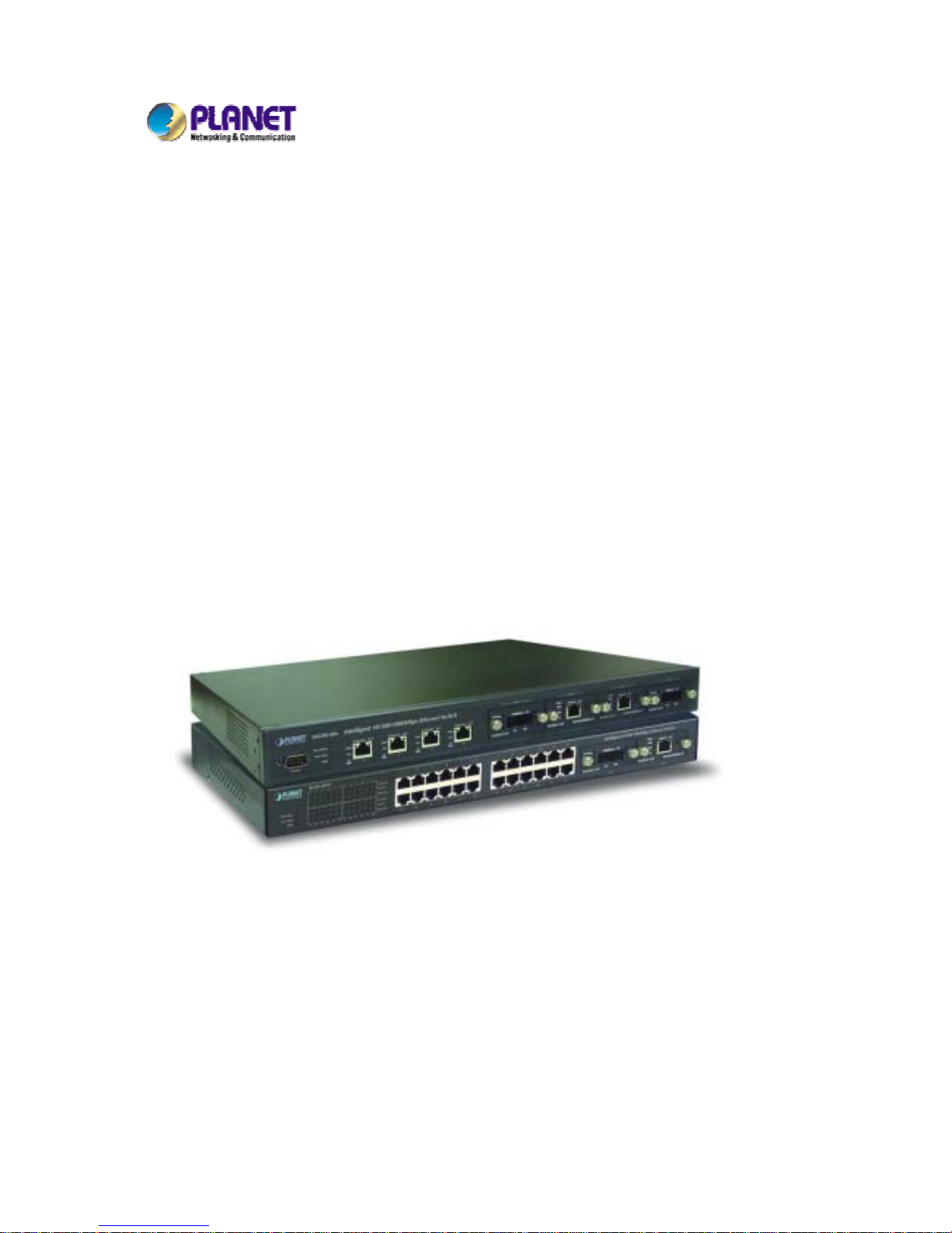
Intelligent Gigabit Ethernet
Stackable / Routing Switch
24 10/100 Mbps Ports + 2 modules slot
WGSW-2402A
4-port Gigabit Ethernet + 4-slot
WGSW-404
User Manual
Page 2

Trademarks
Copyright PLANET Technology Corp. 2002.
Contents subject to revision without prior notice.
PLANET is a registered trademark of PLANET Technology Corp. All other trademarks belong
to their respective owners.
Disclaimer
PLANET Technology does not warrant that the hardware will work properly in all environments
and applications, and makes no warranty and representation, either implied or expressed, with
respect to the quality, performance, merchantability, or fitness for a particular purpose.
PLANET has made every effort to ensure that this User’s Manual is accurate; PLANET
disclaims liability for any inaccuracies or omissions that may have occurred.
Information in this User’s Manual is subject to change without notice and does not represent a
commitment on the part of PLANET. PLANET assumes no responsibility for any inaccuracies
that may be contained in this User’s Manual. PLANET makes no commitment to update or
keep current the information in this User’s Manual, and reserves the right to make
improvements to this User’s Manual and/or to the products described in this User’s Manual, at
any time without notice.
If you find information in this manual that is incorrect, misleading, or incomplete, we would
appreciate your comments and suggestions.
FCC Warning
This equipment has been tested and found to comply with the limits for a Class A digital device,
pursuant to Part 15 of the FCC Rules. These limits are designed to provide reasonable
protection against harmful interference when the equipment is operated in a commercial
environment. This equipment generates, uses, and can radiate radio frequency energy and, if
not installed and used in accordance with the Instruction manual, may cause harmful
interference to radio communications. Operation of this equipment in a residential area is likely
to cause harmful interference in which case the user will be required to correct the interference
at his own expense.
CE Mark Warning
This is a Class A product. In a domestic environment, this product may cause radio
interference, in which case the user may be required to take adequate measures.
Revision
PLANET Intelligent Stackable/Routing Switch User's Manual
FOR MODEL: WGSW-2402A, WGSW-404
REVISION: 1.1
Part No.: EM-WG24A
Page 3

Table of Contents
CHAPTER 1 INTRODUCTION................................................................................................................ 1
1.1 P
ACKAGE CONTENTS
....................................................................................................................... 1
1.2 F
EATURES
....................................................................................................................................... 2
1.3 S
PECIFICATION
................................................................................................................................3
1.4 H
OW TO USE THIS MANUAL
.............................................................................................................. 4
CHAPTER 2 INSTALLATI ON.................................................................................................................6
2.1 WGSW-2402A H
ARDWARE DESCRIPTION
....................................................................................... 6
2.1.1 Front Panel of WGSW-2402A................................................................................................6
2.1.2 LEDs of WGSW-2402A ......................................................................................................... 7
2.1.3 Rear Panel of WGSW-2402A................................................................................................8
2.2 WGSW-404 H
ARDWARE DESCRIPTION
............................................................................................ 8
2.2.1 Front Panel of WGSW-404....................................................................................................8
2.2.2 LEDs of WGSW-404..............................................................................................................9
2.2.3 Rear Panel of WGSW-404...................................................................................................10
2.3 M
ODULE HARDWARE DESCRIPTION
................................................................................................ 10
2.3.1 Gigabit Expansion Module................................................................................................... 10
2.3.2 100Base-FX Expansion Module...........................................................................................11
2.4 I
NSTALLING THE SWITCH
................................................................................................................ 12
2.4.1 Pre-Installation Considerations............................................................................................ 13
2.4.2 Desktop or Shelf Mounting .................................................................................................. 13
2.4.3 Rack-Mounting..................................................................................................................... 14
CHAPTER 3 CONFIGURATION........................................................................................................... 15
3.1 M
ANAGEMENT ACCESS OVERVIEW
................................................................................................. 15
3.1.1 Administration Console........................................................................................................16
3.1.2 Direct Access.......................................................................................................................16
3.1.3 Modem Port Access............................................................................................................. 17
3.2 W
EB MANAGEMENT
....................................................................................................................... 17
3.3 SNMP-B
ASED NETWORK MANAGEMENT
........................................................................................ 18
3.4 P
ROTOCOLS
.................................................................................................................................. 18
3.4.1 Virtual Terminal Protocols....................................................................................................18
3.4.2 SNMP Protocol .................................................................................................................... 18
3.4.3 Management Architecture.................................................................................................... 19
CHAPTER 4 MENU-DRIVEN CONSOLE MANAGEMENT ................................................................. 20
Page 4

4.1 L
OGGING ON TO THE SWITCH
......................................................................................................... 20
4.2 N
AVI GATI NG THROUGH THE CONSOLE INTERFACE
........................................................................... 21
4.3 P
ERFORMING BASIC MANAGEMENT ACTIVITIES
............................................................................... 21
4.3.1 General Management Configuration ................................................................................... 22
4.3.1.1 Changing the System Name........................................................................................................ 23
4.3.1.2 Changing the Contact and Location ............................................................................................ 24
4.3.1.3 Changing the Administration Password....................................................................................... 25
4.3.1.4 Changing the Guest Password.................................................................................................... 27
4.3.1.5 Statistic Collection....................................................................................................................... 28
4.3.1.6 Reboot-On-Error.......................................................................................................................... 29
4.3.1.7 Telnet Logins............................................................................................................................... 30
4.3.1.8 Remote Http Login ...................................................................................................................... 31
4.3.1.9 Returning to the Basic Management Screen............................................................................... 32
4.3.2 LAN Port Configuration........................................................................................................32
4.3.2.1 Changing the Speed and Flow Control ........................................................................................ 33
4.3.2.2 Hiding or Displaying the Port Column.......................................................................................... 36
4.3.2.3 Displaying a Physical Port Address............................................................................................. 37
4.3.2.4 Returning to the Basic Management Screen............................................................................... 38
4.3.3 Console Port Configuration..................................................................................................38
4.3.3.1 Changing the Console Baud Rate............................................................................................... 39
4.3.3.2 Selecting a Flow Control Method................................................................................................. 40
4.3.3.3 Enabling or Disabling Modem Control Options............................................................................ 41
4.3.3.4 Specifying a Modem Setup String ............................................................................................... 42
4.3.3.5 Enabling or Disabling SLIP.......................................................................................................... 43
4.3.3.6 Specifying a SLIP Address.......................................................................................................... 45
4.3.3.7 Specifying a SLIP Subnet Mask.................................................................................................. 46
4.3.3.8 Returning to the Basic Management Screen............................................................................... 47
CHAPTER 5 PERFORMING ADVANCED MANAGEMENT ACTIVITIES........................................... 48
5.1 S
WITCHING DATABASE CONFIGURATION
.......................................................................................... 49
5.2 VLAN & PVID P
ERSPECTIVE
........................................................................................................ 50
5.2.1 Default VLAN....................................................................................................................... 51
5.2.2 Obtaining a VLAN Perspective............................................................................................ 51
5.2.2.1 Creating a New VLAN ................................................................................................................. 52
5.2.2.2 Adding New Switch Ports............................................................................................................ 55
5.2.2.3 Deleting a VLAN ID..................................................................................................................... 60
5.2.2.4 Viewing VLAN Activities .............................................................................................................. 61
5.2.2.5 Viewing VLAN Settings................................................................................................................ 63
5.2.2.6 Adding Ports................................................................................................................................64
Page 5

5.2.2.7 Deleting Ports.............................................................................................................................. 67
5.2.3 Configuring PVID................................................................................................................. 67
5.3 IP M
ULTICAST GROUP PERSPECTIVE
.............................................................................................. 69
5.4 MAC A
DDRESS PERSPECTIVE
....................................................................................................... 73
5.5 P
ORT PERSPECTIVE
...................................................................................................................... 74
5.5.1 Per Port VLAN Activities...................................................................................................... 75
5.5.2 Scrolling Through MAC Addresses ..................................................................................... 77
5.5.3 Hiding or Displaying the Port Column.................................................................................. 77
5.5.4 Per Port Statistics ................................................................................................................ 78
5.5.5 Per Port Mac Limit ............................................................................................................... 81
5.5.6 Returning to the Advanced Management Screen................................................................ 82
5.6 IP N
ETWORKING
............................................................................................................................ 82
5.6.1 IP and RIP Settings .............................................................................................................83
5.6.2 ARP Table Setting................................................................................................................87
5.6.2.1 Adding Static ARP Table Entries................................................................................................. 87
5.6.2.2 Deleting Static ARP Table Entries............................................................................................... 90
5.6.2.3 Searching for ARP Table Entries................................................................................................. 90
5.6.3 Routing Table.......................................................................................................................91
5.6.3.1 Adding Routing Table Entries...................................................................................................... 93
5.6.3.2 Deleting Routing Table Entries.................................................................................................... 95
5.6.3.3 Searching for Routing Table Entries............................................................................................ 95
5.6.4 DHCP Gateway Settings .....................................................................................................96
5.6.5 Ping Settings...................................................................................................................... 100
5.7 B
RIDGING
.................................................................................................................................... 104
5.8 S
TATI C FILTERING
........................................................................................................................ 107
5.8.1 Source MAC Address and Destination MAC Address Out-Filters..................................... 107
5.8.2 MAC Address In-Filters...................................................................................................... 109
5.9 S
PANNING TREE FUNCTIONS
.........................................................................................................110
5.9.1 Spanning Tree Protocol Configurations..............................................................................111
5.9.2 Spanning Tree Port States..................................................................................................116
5.9.3 Spanning Tree Path Costs..................................................................................................118
5.9.4 Spanning Tree Port Priorities.............................................................................................120
5.10 SNMP F
UNCTIONS
.................................................................................................................... 121
5.11 S
TAC KING
.................................................................................................................................. 132
5.11.1 Stacking Basic Setting..................................................................................................... 132
5.11.2 Stack IP Setting........................................................................................................ ........137
5.11.3 Stack Port Mapping.......................................................................................................... 140
5.12 O
THER PROTOCOLS
.................................................................................................................. 140
5.13 P
ORT TRUNKING
........................................................................................................................ 143
Page 6

5.14 P
ORT MIRRORING
...................................................................................................................... 146
5.15 S
ETTING QUALITY OF SERVICE PARAMETERS
.............................................................................. 150
5.15.1 Basic concept .................................................................................................................. 150
5.15.1.1 QoS model .............................................................................................................................. 150
5.15.1.2 Four QoS Profile...................................................................................................................... 152
5.15.1.3 Delay Bound............................................................................................................................ 153
5.15.1.4 Strict Priority and Best Effort ................................................................................................... 153
5.15.1.5 Weighted Fair Queuing............................................................................................................ 154
5.15.1.6 Shaper and DiffServ Expedited Forwarding ............................................................................ 154
5.15.1.7 Rate Control............................................................................................................................ 154
5.15.1.8 WRED Drop Threshold Management Support ........................................................................ 155
5.15.1.9 QoS Flow Control.................................................................................................................... 155
5.15.1.10 Mapping to IETF Diffserv Classes......................................................................................... 156
5.15.2 Configure QoS parameter................................................................................................ 157
5.15.2.1 Setting Global Settings............................................................................................................ 158
5.15.2.2 Specifying TCP/UDP Logical Port Settings ............................................................................. 163
5.15.2.2.1 User-Defined Port............................................................................................................ 164
5.15.2.2.2 Well-Known Port.............................................................................................................. 168
5.15.2.2.3 Range Port ...................................................................................................................... 169
5.15.2.3 Specifying the QoS VLAN Priority ........................................................................................... 173
5.15.2.4 Specifying the ToS Priority...................................................................................................... 175
5.15.2.5 Selecting a QoS Profile ........................................................................................................... 177
5.15.2.5.1 Megabit Profile................................................................................................................. 178
5.15.2.5.2 Gigabit Profiles ................................................................................................................ 182
5.15.2.6 Specifying the Port Configuration............................................................................................ 184
5.15.2.7 Selecting Rate Control Parameters......................................................................................... 186
5.16 S
ENDING AND RECEIVING FILES
................................................................................................. 190
5.16.1 Receiving Files via TFTP................................................................................................. 191
5.16.2 Sending Files via TFTP ................................................................................................... 193
5.16.3 Receiving Files via Kermit ............................................................................................... 195
5.16.4 Sending Files via Kermit..................................................................................................196
CHAPTER 6 WEB-BASED BROWSER MANAGEMENT.................................................................. 199
6.1 L
OGGING ON TO THE SWITCH
....................................................................................................... 199
6.2 U
NDERSTANDING THE BROWSER INTERFACE
................................................................................. 200
6.3 P
ERFORMING FILE ACTIVITIES
...................................................................................................... 201
6.3.1 Receiving Files via TFTP...................................................................................................202
6.4 P
ERFORMING BASIC SETUP ACTIVITIES
........................................................................................ 203
6.4.1 General Management Configuration ................................................................................. 203
Page 7

6.4.2 Configuring LAN Ports.......................................................................................................205
6.4.3 Console Port Configuration................................................................................................209
CHAPTER 7 PERFORMING ADVANCED SETUP ACTIVITIES..................................................... 213
7.1 MAC A
DDRESS MANAGEMENT
..................................................................................................... 214
7.1.1 Per VLAN View.................................................................................................................. 215
7.1.2 Per Port View.....................................................................................................................216
7.1.3 Individual MAC View..........................................................................................................218
7.2 IP N
ETWORKING
.......................................................................................................................... 219
7.2.1 IP and RIP Settings ...........................................................................................................220
7.2.2 Default Gateway Settings.................................................................................................. 224
7.2.3 ARP Table Settings............................................................................................................ 225
7.2.4 DHCP Gateway Settings ................................................................................................... 225
7.3 P
ER PORT STATI STICS
................................................................................................................. 227
7.4 B
RIDGING
.................................................................................................................................... 228
7.5 S
TATI C
MAC F
ILTERS
.................................................................................................................. 229
7.5.1 Adding Source MAC Address Out-Filters.......................................................................... 230
7.5.2 Deleting Source MAC Address Out-Filters........................................................................ 232
7.5.3 Adding Destination MAC Address Out-Filters ................................................................... 233
7.5.4 Deleting Destination MAC Address Out-Filters ................................................................. 234
7.6 IP M
ULTICAST GROUP
................................................................................................................. 235
7.7 VLAN & PVID P
ERSPECTIVE
...................................................................................................... 237
7.7.1 VLAN Configuration........................................................................................................... 238
7.7.1.1 Adding a VLAN.......................................................................................................................... 238
7.7.1.2 Updating VLAN Information....................................................................................................... 241
7.7.1.3 Deleting a VLAN........................................................................................................................ 242
7.7.2 PVID Setting ...................................................................................................................... 243
7.8 S
PANNING TREE PERSPECTIVE
.................................................................................................... 244
7.8.1 Configurations.................................................................................................................... 245
7.8.2 Port Setting........................................................................................................................ 247
7.9 V
IEWING AND/OR CHANGING
SNMP P
ARAMETERS
........................................................................ 249
7.10 C
ONFIGURING
GVRP
AND
IGMP ............................................................................................... 251
7.11 P
ORT TRUNKING
........................................................................................................................ 252
7.12 P
ORT MIRRORING
...................................................................................................................... 254
7.13 S
ELECTING STAC KING SETTINGS
................................................................................................ 257
CHAPTER 8 SNMP AND RMON MANAGEMENT.......................................................................... 259
8.1 O
VERVIEW
.................................................................................................................................. 259
8.2 SNMP A
GENT AND
MIB-2 (RFC1213) ........................................................................................ 260
8.3 RMON MIB (RFC 1757)
AND BRIDGE
MIB (RFC 1493) ............................................................. 260
Page 8

8.3.1 RMON Groups Supported ................................................................................................. 261
8.3.2 Bridge Groups Supported..................................................................................................261
8.4 PLANET P
RI VATE
MIB................................................................................................................ 262
APPENDIX A CABLE SPECIFICATIONS ....................................................................................... 263
APPENDIX B EXAMPLE OF STACKING SWITCHES.................................................................... 265
APPENDIX C VLAN .........................................................................................................................267
C.1 A
SSIGNING PORTS TO
VLANS..................................................................................................... 268
C.1.1 VLAN Classification........................................................................................................... 268
C.1.2 Port Overlapping............................................................................................................... 268
C.1.3 Port-based VLANs ............................................................................................................268
C.1.4 Automatic VLAN Registration (GVRP)..............................................................................268
C.2 F
ORWARDING TAGGED/UNTAGGED FRAMES
................................................................................. 269
C.3 C
ONNECTING
VLAN G
ROUPS
..................................................................................................... 270
APPENDIX D VLAN OVERLAPPING.............................................................................................. 272
APPENDIX E CONSOLE PORT PIN ASSIGNMENT......................................................................275
B.1 DB9 P
ORT PIN ASSIGNMENTS
..................................................................................................... 275
B.2 C
ONNECTION FROM SWITCH'S SERIAL PORT TO
PC'S 9-P
IN
COM P
ORT
....................................... 276
B.3 C
ONNECTION FROM SWITCH'S SERIAL PORT TO MODEM'S
25-P
IN
DCE P
ORT
............................... 276
B.4 C
ONNECTION FROM SWITCH'S SERIAL PORT TO
PC'S 25-P
IN
DTE P
ORT
...................................... 277
Page 9

- 1 -
CHAPTER 1 INTRODUCTION
WGSW-404 and WGSW-2402A are ultra-fast high-performance switches with non-blocking switch
fabric of 16Gbps and 12.8Gbps. WGSW-404 is a backbone switch with 4-port 10/100/1000Mbps
RJ-45 and 4-slot for media expansion. WGSW-2402A is designed to be a workgroup switch with
24-port 10/100Mbps RJ-45 and 2-slot for media expansion. Their expansion slots support
1000Base-T, 1000Base-SX and 100Base-FX modules that provide great flexibility on enterprise and
FTTB application. In the following section, the short term “WGSW” will be used to represent both
WGSW-2402A and WGSW-404
The WGSW switch can be stacked up to 8 units together through Ethernet interface and managed by
single IP. You can stack 8 WGSW-2402A to get up to 192 100Base-TX ports plus 2 Gigabit port or 8
WGSW-404 to get 50 Gigabit ports in single stack. Mix them in a single stack is also possible to get
maximum flexibility. Most stacked switches are limited by the length of a proprietary stack cable,
WGSW switch, however, the maximum distance between two stacked switches can be up to 2
kilometers using Ethernet stack connectivity.
Designed as the Layer 2 switch but with layer 3 software routing function, the WGSW can easily fit in
your network configuration and can be executed for its management functions through the console
telnet and the web. SNMP MIBII, Bridge MIB, RMON groups 1,2,3,9 and enterprise private MIB are
also supported to get the maximum management functionality.
The standard IEEE 802.1Q with VLAN tagging feature makes logically separating nodes easier, with up
to 128 VLAN groups allowed on the WGSW switch. IGMP snooping is provided to prevent flooding of IP
multicast traffic. Port security and MAC addresses filtering are also included as a standard feature to
enhance overall network access security.
8 priority queues on Gigabit port and 4 on 10/100port are provided with versatile scheduling methods
including delay bound, strict priority, WFQ and best effort. This ensures critical applications get the
bandwidth and priority they need. Rate control is also supported to allow bandwidth allocation based
on ports.
Throughout this user’s manual, the Intelligent Gigabit Ethernet Switch, WGSW-404 and WGSW-2402A
will be referred to as the Managed Switch or the Switch or WGSW.
1.1 Package Contents
The package contains the following:
Page 10

- 2 -
One Intelligent Gigabit Ethernet Switch
One Power Cord
Rack Mounting Brackets
One Serial/Console Cable
User’s manual CD
Quick Installation Guide
If any of these pieces are missing or damaged, please contact your dealer immediately, if possible,
retain the carton including the original packing material, and use them against to repack the product in
case there is a need to return it to us for repair.
1.2 Features
Complies with IEEE 802.3, 802.3u, 802.3z and 802.3ab Ethernet Standards, IEEE 802.3x flow
control, 802.1D Spanning Tree, 802.1p QoS and 802.1Q VLAN.
Features Store-and-Forward mode with wire-speed filtering and forwarding rates
Support 16k MAC addresses
IEEE 802.3x full duplex PAUSE frame, half duplex back pressure flow control
Runt and CRC filtering eliminates erroneous packets to optimize network bandwidth
LED indicators for simple diagnostics and management
Auto-MDI/MDI-X on each 100Base-TX and 1000Base-T port
Software routing function with RIP, RIP-2, DHCP relay and proxy ARP support
Can be configured up to 128 groups of 802.1Q VLANs with GARP/GVRP supports
Support port trunking for maximum 4 ports per trunk
Support IP Multicast with IGMP snooping
Up to 8 units can be stacked by Ethernet connection and managed by single IP
Provide 4 priority queues on 10/100 ports and 8 priority queues on Gigabit ports
Queuing is based on IEEE 802.1p tag or ToS of IP layer
Configurable frame scheduling methods including delay bound, strict priority, weighted fair
queuing and best effort
Rate control is supported on 10/100Mbps ports to provide 10 levels of rate (10Mbps to 100Mbps)
Support SNMP MIB II, Ethernet MIB, VLAN MIB, RMON group 1, 2, 3, 9 and enterprise private
MIB
Support Port mirroring on WGSW-2402A
Page 11

- 3 -
1.3 Specification
Product
WGSW-2402A WGSW-404
Hardware Specification
Ports
24 10/ 100Base-TX RJ-45
Auto-MDI/MDI-X ports
4 10/100/1000Base-T RJ-45
Auto-MDI/MDI-X ports
Module Slot for
1000Base-SX/T and
100Base-FX modules
2 4
Stack Interface
Through Ethernet interface. Up to 8 units can be managed by
single IP
Switch Fabric
12.8Gbps 16Gbps
Switch Processing Scheme
Store-and-forward
Throughput (packet per
second)
6.547Mpps 11.904Mbps
Address Table
16K entries
Queue Buffer
2Mbytes 4Mbytes
Flow Control
Back pressure for half duplex, IEEE 802.3x Pause Frame for full
duplex
Dimensions 430 x 350 x 44.5 mm, 1U high
Weight
4.4 kg 4.2 kg
Power Requirement
100~240 VAC, 50-60 Hz
Power Consumption
50 Watts maximum 60 Watts maximum
Heat Dissipation
170 BTU/hr maximum 205 BTU/hr maximum
Temperature
Operating: 0~50ºC, Storage -40~70ºC
Humidity
Operating and Storage: 10% to 95%(Non-condensing)
Network Management
System Configuration
Console port, Telnet, Web browser, SNMP/RMON
Management Agent
MIB II, Ethernet MIB, RMON MIB, VLAN MIB and enterprise
private MIB
RMON
Groups 1, 2, 3, 9 (Statistics, History, Alarm and Event)
Spanning Tree Algorithm
IEEE 802.1D
VLAN
802.1Q VLAN with GARP/GVRP, up to 128 VLANs supported
Routing
RIP, RIP-2, DHCP Relay, proxy ARP and ICMP Router
Discovery Message
Static Address Filtering
Source and destination MAC addresses filtering
IGMP Multicast Filtering
Support IP multicast with IGMP snooping up to 64k groups
Port trunking
Up to 4 ports in a trunk. 3
trunk groups support
Up to 4 ports in a trunk. 4
trunk groups support
Port Mirroring
2 mirroring port supports
QoS
Based on IEEE 802.1p tag or ToS of IP layer
Priority Queue
4 priority queues on 10/100 ports and 8 priority queues on
Page 12

- 4 -
Gigabit ports
QoS Scheduling
Supports delay bound, strict priority, WFQ (Weighted Fair
Queuing) and best effort service disciplines
Congestion Avoidance
Supports WRED (Weighted Random Early Detection) drop
threshold management
Rate Control
10 levels of rate (10 to 100%)
configurable on 10/100Mbps
port
-
Standards Conformance
Regulation Compliance
FCC Part 15 Class A, CE
Standards Compliance
IEEE 802.3 (Ethernet)
IEEE 802.3u (Fast Ethernet),
IEEE 802.3z (1000Base-SX/LX),
IEEE 802.3ab(1000Base-T),
IEEE 802.1D (STP),
IEEE 802.3x (full-duplex flow control),
IEEE 802.1p (QoS),
IEEE 802.1Q (VLANs)
RFC 768 UDP
RFC 783 TFTP
RFC 791 IP
RFC 792 ICMP
RFC 826 ARP
RFC 854 Telnet
RFC 1058 RIP
RFC 1122 Host Requirements
RFC 1157 SNMP v1/v2
RFC 1256 ICMP Router Discover Protocol
RFC 1213 MIB II
RFC 1493 Bridge MIB
RFC 1757 RMON 4 groups, statistics, history, alarms and events
RFC 1812 IP Router Requirement
RFC 2131 DHCP Relay
RFC 2068 HTTP
RFC 2236 IGMPv2
RFC 2674 VLAN MIB
1.4 How to Use this Manual
This user’s manual is structured as follows:
Chapter 2, Installation explains the hardware functions of the Switch and how to physically install
it.
Chapter 3, Configuration explains how to set up and modify the configuration of the Switch.
Chapter 4, Menu-Driven Console Management and Chapter 5 Performing Advanced
Management Activities explains how to configure either locally through its RS-232 port or
remotely via a Telnet session.
Chapter 6 Web-Based Configuration and Chapter 7 Performing Advanced Setup Activities allows
you to access the Switch using the Web browser of your choice.
Page 13

- 5 -
Chapter 8, SNMP and RMON Management allows you to access the Switch using SNMP
management feature.
Appendix provides cable specification and more information regarding to stack and VLAN.
Page 14
- 6 -
CHAPTER 2 INSTALLATION
This Chapter describes the hardware function of the Switches and shows how to install it on the
desktop or shelf. Basic knowledge of networking is assumed. Read this chapter completely before
continuing.
2.1 WGSW-2402A Hardware Description
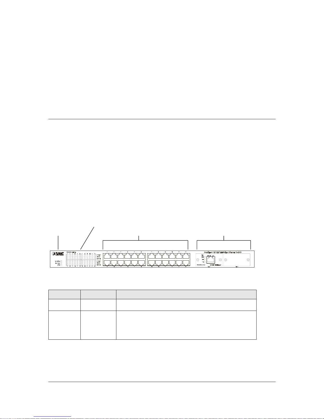
2.1.1 Front Panel of WGSW-2402A
The front panel of the Switch has 24 RJ-45 ports for 10/100 Mbps in the middle. The port status LEDs
are indicated at the left. The expansion modules are situated at the right. Figure 2-1 shows a front
panel of the Switch. Table 2-1 shows the port function of the Switch. The functionality of the LEDs will
be explained in 2.1.4 LEDs.
F
IGURE
2-1 F
RONT PANEL
LEDs
Status LEDs 10/100 RJ-45 Ports Expansion Modules
T
ABLE
2-1 P
ORT FUNCTION
Ports
# of Ports Description
10/100
24
These RJ-45 ports support network speeds of either 10Mbps or
100 Mbps, and can operate in half- or full-duplex modes.
Expansion
Ports
2
These ports provide for the installation of one or two expansion
modules that establish a Fast or Gigabit Ethernet connection.
Note: You may install an 1000Base-SX, 1000Base-T or
100Base-FX expansion module and use fiber optic or category
5 cabling
Page 15
- 7 -
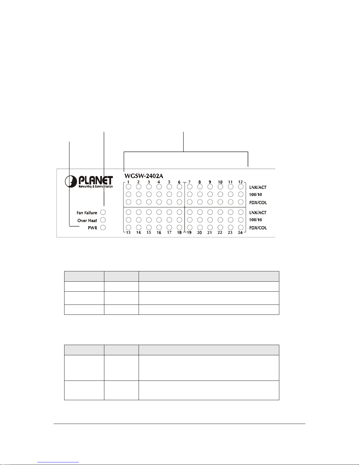
2.1.2 LEDs of WGSW-2402A
The LEDs indicate the status of 10/100 Mbps Ethernet ports, Over Heat, Fan Failure and Power. Figure
2-2 shows the LED panel of the Switch. Table 2-2 shows the functions of power and status LEDs. Table
2-3 shows the functions of the port status LEDs.
F
IGURE
2-2 LEDS P
ANEL
Status LED 10/100 Port Status LEDs
Power LED
The LEDs are explained in the following tables.
T
ABLE
2-2 P
OWER AND STATUS
LEDS
LED Color Function
PWR
Green
Lights to indicate that the Switch has power.
Over Heat
Red
Lights to indicate that the Switch exceeds its operational
temperature.
Fan Failure
Red
Lights to indicate that the fans are not active.
T
ABLE
2-3 P
ORT STATUS
LEDS
LED Color Function
Link/Act
Green
Lights to indicate that the Switch is successfully
connecting to the network.
Blinks to indicate the Switch is actively receiving or
sending the data over the port.
100/10
Green
Lights to indicate that the port is operating at 100 Mbps.
Off to indicate that the port is operating at 10 Mbps while
the port’s Link is on.
Page 16
- 8 -
FDX/COL
Yellow
Lights to indicate that the port is operating in full-duplex
mode.
Blinks periodically to indicate that the connection is
experiencing collisions.
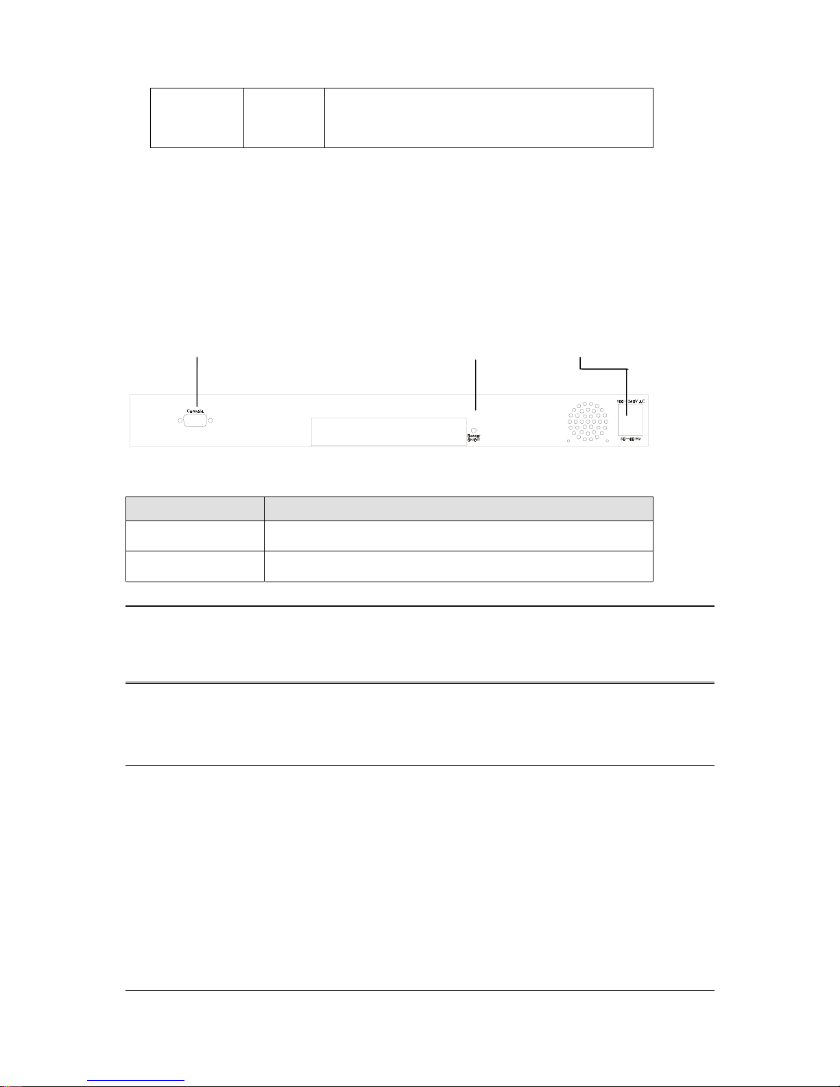
2.1.3 Rear Panel of WGSW-2402A
The rear panel of WGSW-2402A has a power connector, a Buzzer button and a console port. Figure
2-3 shows a rear panel of the Switch. Table 2-5 explains the function of the ports shown in the Figure
2-4.
F
IGURE
2-3 R
EAR PANEL OF
WGSW-2402A
Console Buzzer Button Power
T
ABLE
2-4 P
ORT FUNCTION OF THE REAR PANEL
Port Function
Power
This is where you will connect the AC power cord. 100~240VAC is
allowed.
Console
This is where you will connect to the RS-232 serial port on your PC
for configuring the management function, discussed in Chapter 3.
Note: To depress the Buzzer button will change the reaction of the buzzer. If the button is set to on,
the buzzer will ring as the system is under the status of overheat. Set to off, the buzzer will not
work even if the system overheats.
2.2 WGSW-404 Hardware Description
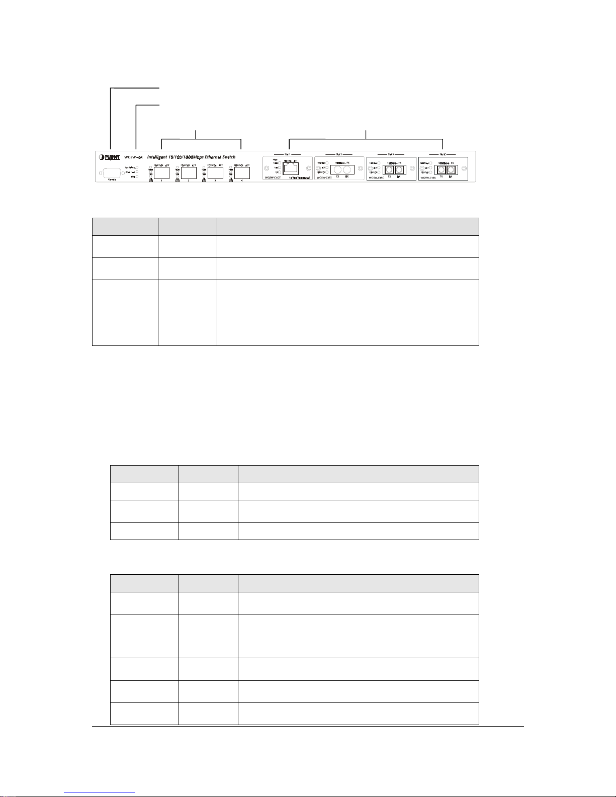
2.2.1 Front Panel of WGSW-404
The front panel of the WGSW-404 has 4 RJ-45 ports for 10/100/1000 Mbps in the middle. The port
status LEDs are indicated at the left. The expansion modules are situated at the right. Figure 2-3 shows
the Switch’s front panel. Table 2-4 shows the port function of the Switch. The functionality of the LEDs
will be explained in 2.2.2 LEDs.
Page 17
- 9 -
F
IGURE
2-4 F
RONT PANEL OF
WGSW-404
Console
Status LEDs
10/100/1000 Mbps ports Expansion Ports
T able 2-5 Port Function
T
ABLE
2-5 P
ORT FUNCTION
Ports # of Ports Description
Console
1
This is where you can connect to the RS-232 serial port on
your PC for configuring the management function.
10/100/1000
4
These RJ-45 ports support network speeds of 10, 100 or 1000
Mbps, and can operate in full-duplex modes.
Expansion
Ports
4
These ports provide for the installation of one or two
expansion modules that establish a Fast or Gigabit Ethernet
connection.
Note: You may install an 1000Base-SX, 1000Base-T or
100Base-FX expansion module and use fiber optic or
category 5 cabling.
2.2.2 LEDs of WGSW-404
The LEDs indicate the status of 10/100/1000 Mbps Ethernet ports, Over Heat, Fan Failure and Power.
The LEDs are explained in the following tables.
T
ABLE
2-6 P
OWER AND STATUS
LEDS
LED Color Function
Power
Green
Lights to indicate that the Switch has power.
Over Heat
Red
Lights to indicate that the Switch exceeds its operational
temperature.
Fan Failure
Red
Lights to indicate that the fans are not active.
T
ABLE
2-7 P
ORT STATUS
LEDS
LED Color Function
Act
Green
Lights to indicate the Switch is actively receiving or
sending the data over the port.
FDX/COL
Yellow
Lights green to indicate that the port is operating in
full-duplex mode.
Blinks orange periodically to indicate that the connection
is experiencing collisions.
1000
Green
Lights to indicate that the Switch is sending or receiving
data at 1000 Mbps.
100
Green
Lights to indicate that the Switch is sending or receiving
data at 100 Mbps.
10
Yellow
Lights to indicate that the Switch is sending or receiving
data at 10 Mbps.
Page 18

- 10 -
2.2.3 Rear Panel of WGSW-404
The rear panel of WGSW-404 has a power connector, a Buzzer button and a console port. Figure 2-3
shows a rear panel of the Switch. Table 2-5 explains the function of the ports shown in the Figure 2-4.
F
IGURE
2-5 R
EAR PANEL OF
WGSW-404
Buzzer Button Power
T
ABLE
2-8 P
ORT FUNCTION OF THE REAR PANEL
Port Function
Power
This is where you will connect the AC power cord.
Note: To depress the Buzzer button will change the reaction of the buzzer. If the button is set to on,
the buzzer will ring as the system is under the status of overheat. Set to off, the buzzer will not
work even if the system overheats.
2.3 Module Hardware Description
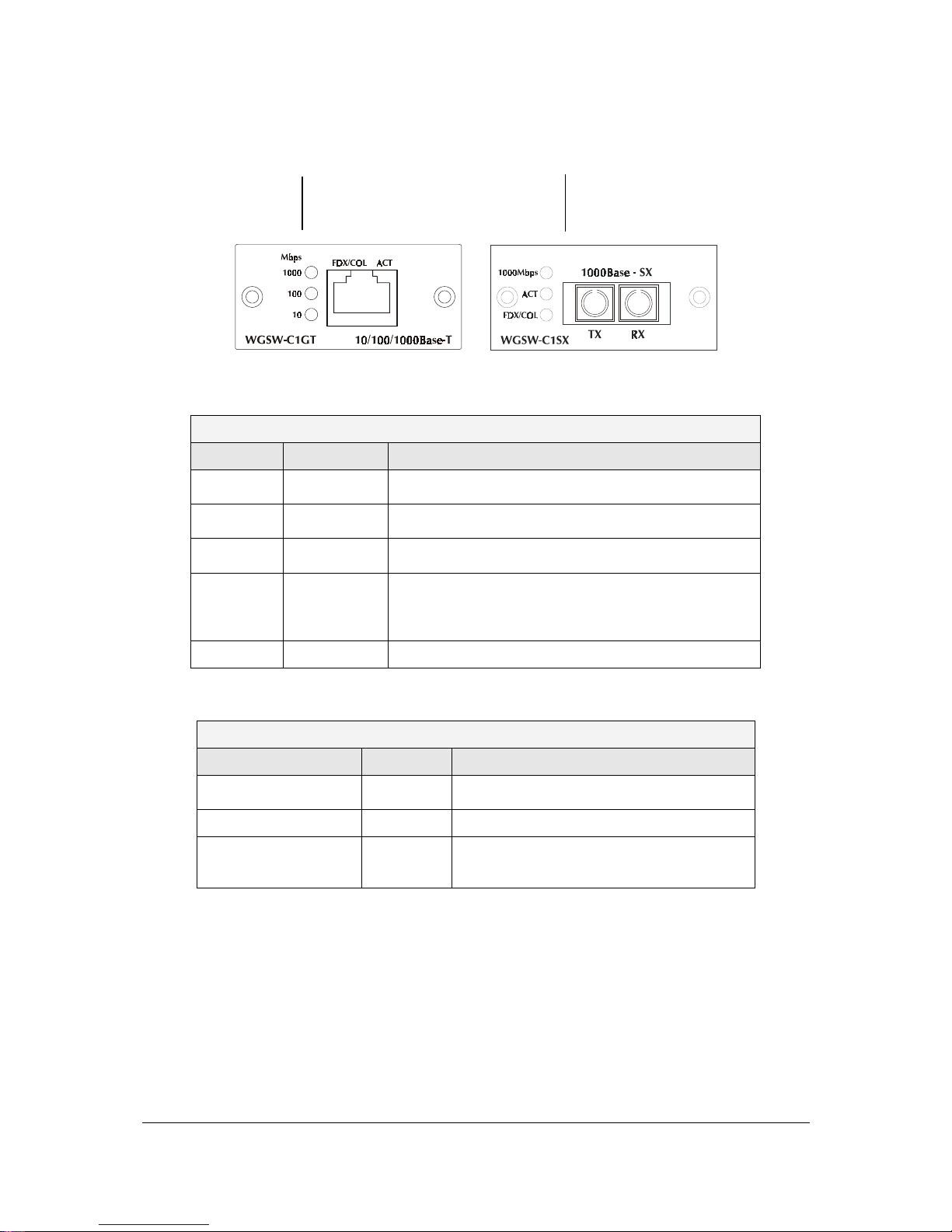
2.3.1 Gigabit Expansion Module
Figure 2-6 show that front panel of gigabit expansion module. Table 2-9 and Table 2-10 show that
modules status LEDs.
Page 19
- 11 -
F
IGURE
2-6 G
IGABIT EXPANSION MODULE
WGSW-C1GT Module Status LEDs WGSW-C1SX Module Status LEDs
T
ABLE
2-9 WGSW-C1GT/SX S
TATUS
LEDS
WGSW-C1GT
LED Color Function
1000
Green
Lights to indicate that the Switch is sending or receiving
data at 1000 Mbps.
100
Green
Lights to indicate that the Switch is sending or receiving
data at 100 Mbps.
10
Yellow
Lights to indicate that the Switch is sending or receiving
data at 10 Mbps.
FDX/COL
Yellow
Lights green to indicate that the port is operating in
full-duplex mode.
Blinks orange periodically to indicate that the connection
is experiencing collisions.
Act
Green
Lights to indicate that the connection is acting.
T
ABLE
2-10 WGSW-C1SX S
TATUS
LEDS
WGSW-C1SX
LED Color Function
1000
Green
Lights to indicate that receiver of fibre port is in
normal optical input levels.
Act
Green
Lights to indicate that the connection is acting.
FDX/COL
Yellow
Lights to indicate that the port is operating at
full duplex. This port does not support half
duplex.
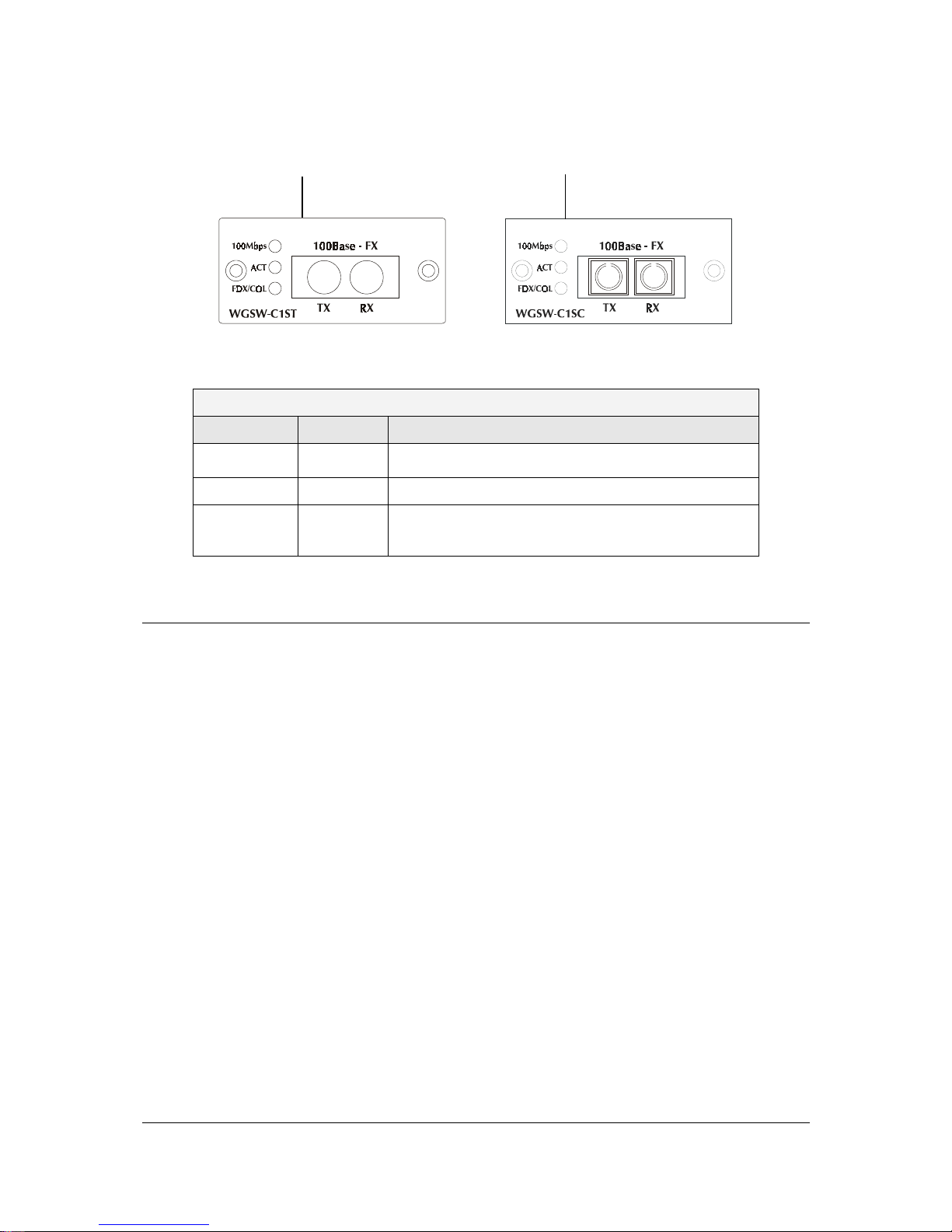
2.3.2 100Base-FX Expansion Module
Figure 2-5 show that front panel of 100Base-FX expansion module. Table 2-7 show that modules
status LEDs.
Page 20
- 12 -
F
IGURE
2-7 100B
ASE
-FX E
XPANSION MODULE
WGSW-C1ST Module Status LEDs WGSW-C1SC Module Status LEDs
T
ABLE
2-11 100B
ASE
-FX
MODULE STATUS
LEDS
WGSW-C1SC / WGSW-C1ST
LED Color Function
100
Green
Lights to indicate that receiver of fibre port is in normal
optical input levels.
Act
Green
Lights to indicate that the connection is acting.
FDX/COL
Yellow
Lights to indicate that the port is operating at full duplex.
Blinks orange periodically to indicate that the connection
is experiencing collisions.
2.4 Installing the Switch
The Switch is designed for office use, where it can be free standing, desktop-mounted, or mounted in
most standard 19-inch equipment racks. If you prefer, you can rack-mount the Switch in a wiring closet
or equipment room using two mounting brackets and six screws.
When choosing a location for the Switch, observe the following guidelines:
Make sure the Switch is accessible and that the cables can be connected easily.
Keep cabling away from sources of electrical noise such as radios, transmitters, and broadband
amplifiers as well as power lines and fluorescent lighting fixtures.
Prevent water or moisture from entering the Switch case.
Make sure there are no obstructions to restrict airflow around the Switch. We recommend that you
provide a minimum of 25 millimeter (1-inch) clearance.
Do not place liquids or other objects on top of the Switch.
If the Switches are freestanding, do not stack more than four switches on top of one another.
Page 21

- 13 -
2.4.1 Pre-Installation Considerations
Fast Ethernet Topology Considerations
If you will be using the Switch for Fast Ethernet (100 Mbps) operation, observe the following guidelines:
The maximum unshielded twisted-pair (UTP) cable length is 100 meters (328 feet) over Category 5
cable.
Single-repeater topologies permit a total network span of 325 meters (1066 feet).
Full-Duplex Considerations
The Switch provides full-duplex support for its Fast Ethernet ports. Full-duplex operation allows frames
to be sent and received simultaneously, doubling a link’s potential data throughput. If you will be using
the Switch in full-duplex mode, the maximum UTP cable length is 100 meters (328 feet) over Category
5 cable.
2.4.2 Desktop or Shelf Mounting
To install the Switch on a desktop or shelf, simply complete the following steps:
Step 1 Place the Switch on a desktop or shelf near an AC power source.
Step 2 Keep enough ventilation space between the Switch and the surrounding objects.
Note: When choosing a location, keep in mind the environmental restrictions. Please also
refer to Chapter 1, section 1.3 product specification for the details.
Step 3 Connect the Switch to network devices.
A. Connect one end of a standard network cable to the 10/100 RJ-45 ports on the front of
the Switch.
B. Connect the other end of the cable to the network devices such as printer servers,
workstations or routers.
C.
Note: It is strongly recommended to use the UTP Category 5 network cabling with RJ-45 tips
for the network connection. For more information, please see the Cable Specifications
in Appendix A, Cable Specifications.
Step 4 Supply power to the Switch.
A. Connect one end of the power cable to the Switch.
B. Connect the power cube end of the power cable to a standard wall outlet.
When the Switch receives power, the Power LED should remain solid Green.
Page 22
- 14 -
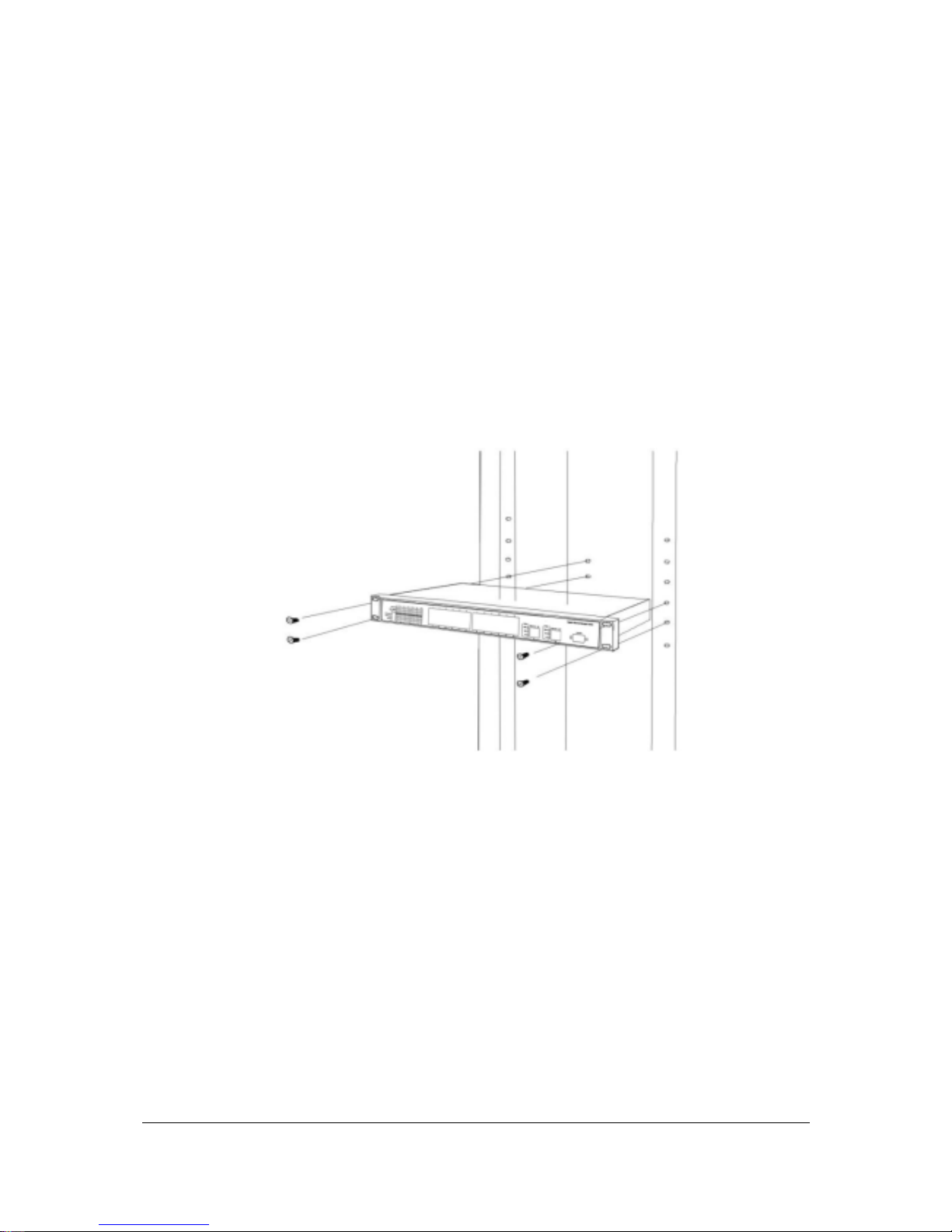
2.4.3 Rack-Mounting
The following procedure describes how to install the Switch in a standard 19-inch rack.
Disconnect all cables from the Switch.
Remove all adhesive pads from the bottom of the Switch.
Step 1 Place the Switch right side up on a hard flat surface, with the front panel facing you.
Step 2 Locate a mounting bracket over the mounting holes on one side of the Switch
F
IGURE
2-8 L
OCATING A MOUNTING BRACKET
Step 3 Insert three screws and use a screwdriver to secure.
Step 4 Repeat the two previous steps for the other side of the Switch.
Step 5 Insert the Switch into the 19-inch rack and secure with suitable screws. Make sure the
ventilation holes on the Switch are not obstructed.
Step 6 Connect the cables to the back of the Switch.
Page 23

- 15 -
CHAPTER 3 CONFIGURATION
This chapter explains the methods that you can use to configure management access to the Switch. It
describes the types of management applications and the communication and management protocols
that deliver data between your management device (workstation or personal computer) and the system.
It also contains information about port connection options.
This chapter covers the following topics:
Management Access Overview
Key Concepts
Key Guidelines for Implementation
Administration Console Access
Web Management Access
SNMP Access
Standards, Protocols, and Related Reading
3.1 Management Access Overview
The Switch gives you the flexibility to access and manage the Switch using any or all of the following
methods:
An administration console
Web browser interface
An external SNMP-based network management application
The administration console and Web browser interface support are embedded in the Switch software
and are available for immediate use. Each of these management methods has their own advantages.
Table 3-1 compares the three management methods.
T
ABLE
3-1 C
OMPARISONS OF THREE MANAGEMENT METHODS
Management
Method
Advantages Disadvantages
Administration
console
No IP address or subnet needed
Text-based
Telnet functionality and HyperTerminal
built into Windows 95/98/NT/2000/XP
operating systems
Secure
Must be near switch or use dial-up
connection
Not convenient for remote users
Modem connection may prove to
be unreliable or slow
Web browser
Ideal for configuring the Switch
remotely
Compatible with all popular browsers
Security can be compromised
(hackers need only know the IP
address and subnet mask)
Page 24

- 16 -
Can be accessed from any location
Most visually appealing
May encounter delay times on
poor connections
SNMP Agent
Communicates with switch functions at
the MIB level
Based on open standards
Requires SNMP manager
software
Least visually appealing of all
three methods
Some settings require calculations
Security can be compromised
(hackers need only know the
community name)
3.1.1 Administration Console
The administration console is an internal, character-oriented, menu-driven user interface for performing
system administration such as displaying statistics or changing option settings. Using this method, you
can view the administration console from a terminal, personal computer, Apple Macintosh, or
workstation connected to the Switch’s console (serial) port.
There are two ways to use this management method: via direct access or modem port access. The
following sections describe these methods. For more information about using the console, refer to
Chapter 4 Menu-Driven Console Management.
3.1.2 Direct Access
Direct access to the administration console is achieved by directly connecting a terminal or a PC
equipped with a terminal-emulation program (such as HyperTerminal) to the Switch console (serial)
port.
When using this management method, a null-modem cable is required to connect the Switch to the PC.
After making this connection, configure the terminal-emulation program to use the following
parameters:
The default parameters are:
115,200 bps
8 data bits
No parity
1 stop bit
You can change these settings, if desired, after you log on. This management method is often preferred
because you can remain connected and monitor the system during system reboots. Also, certain error
messages are sent to the serial port, regardless of the interface through which the associated action
was initiated. A Macintosh or PC attachment can use any terminal-emulation program for connecting to
the terminal serial port. A workstation attachment under UNIX can use an emulator such as TIP.
Page 25

- 17 -
3.1.3 Modem Port Access
You can access the Switch’s administration console from a PC or Macintosh using an external modem
attached to the console (serial) port. The Switch management program provides a Console Port
screen, accessible from the Basic Management screen, that lets you configure parameters for modem
access (see Chapter 4 Menu-Driven Console Management). After configuring when you have
configured the external modem from the administration console, the Switch transmits characters that
you have entered as output on the modem port. The Switch echoes characters that it receives as input
on the modem port to the current ad-ministration console session. The console appears to be directly
connected to the external modem.
3.2 Web Management
The Switch provides a browser interface that lets you configure and manage the Switch remotely. After
you set up your IP address for the Switch, you can access the Switch’s Web interface applications
directly in your Web browser by entering the IP address of the Switch. You can then use your Web
browser to list and manage switch configuration parameters from one central location, just as if you
were directly connected to the Switch’s console port. For more information, see Chapter 5, Browser
Management.
Web Management requires either Microsoft Internet Explorer 4.01 or later or Netscape Navigator 4.03
or later.
Netscape Navigator — if you use Netscape Navigator 4.03 or 4.04, install the Netscape JDK 1.1
Patch. Download the patch from the following location:
http://www.netscape.com/
If you encounter problems accessing Help files when you use Netscape, clear the browser memory
cache and disk cache, and restart the browser.
Internet Explorer — if you use Internet Explorer 4.01, install the latest 4.01 Service Pack 1. This
service pack makes Internet Explorer Year 2000 compliant and fixes other product-support issues.
Download the 4.01 Service Pack 1 from the following location:
http://www.microsoft.com/msdownload/iebuild/ie4sp1_win32/en/ie4sp1_win32.htm
If the above link is unavailable, download the service pack from the Microsoft home page:
http://www.microsoft.com
Page 26

- 18 -
3.3 SNMP-Based Network Management
You can use an external SNMP-based application to configure and manage the Switch. This
management method requires the SNMP agent on the Switch and the SNMP Network Management
Station to use the same community string. This management method, in fact, uses two community
strings: the get community string and the set community string. If the SNMP network management
station only knows the set community string, it can read and write to the MIBs. However, if it only knows
the get community string, it can only read MIBs. The default gets and sets community strings for the
Switch are public.
3.4 Protocols
The Switch supports the following protocols:
Virtual terminal protocols, such as Telnet
Simple Network Management Protocol (SNMP)
3.4.1 Virtual Terminal Protocols
A virtual terminal protocol is a software program, such as Telnet, that allows you to establish a
management session from a Macintosh, a PC, or a UNIX workstation. Because Telnet runs over
TCP/IP, you must have at least one IP address configured on the Switch before you can establish
access to it with a virtual terminal protocol.
Note: Terminal emulation differs from a virtual terminal protocol in that you must connect a terminal
directly to the console (serial) port.
3.4.2 SNMP Protocol
Simple Network Management Protocol (SNMP) is the standard management protocol for multi-vendor
IP networks. SNMP supports transaction-based queries that allow the protocol to format messages and
to transmit information between reporting devices and data-collection programs. SNMP runs on top of
the User Datagram Protocol (UDP), offering a connectionless-mode service.
Page 27

- 19 -
3.4.3 Management Architecture
All of the management application modules use the same Messaging Application Programming
Interface (MAPI). By unifying management methods with a single MAPI, configuration parameters set
using one method (console port, for example) are immediately displayable by the other management
methods (for example, SNMP agent of Web browser).
The management architecture of the Switch adheres to the IEEE open standard. This compliance
assures customers that the Switch is compatible with, and will interoperate with other solutions that
adhere to the same open standard.
Page 28
- 20 -
Chapter 4 Menu-Driven Console Management
The Switch provides a menu-driven console interface for configuration purposes. The Switch can be
configured either locally through its RS-232 port or remotely via a Telnet session. This chapter
describes how to configure the Switch using its menu-driven console. The figures in this chapter will
base on WGSW-2402A, for WGSW-404, however, the setup steps are the same.
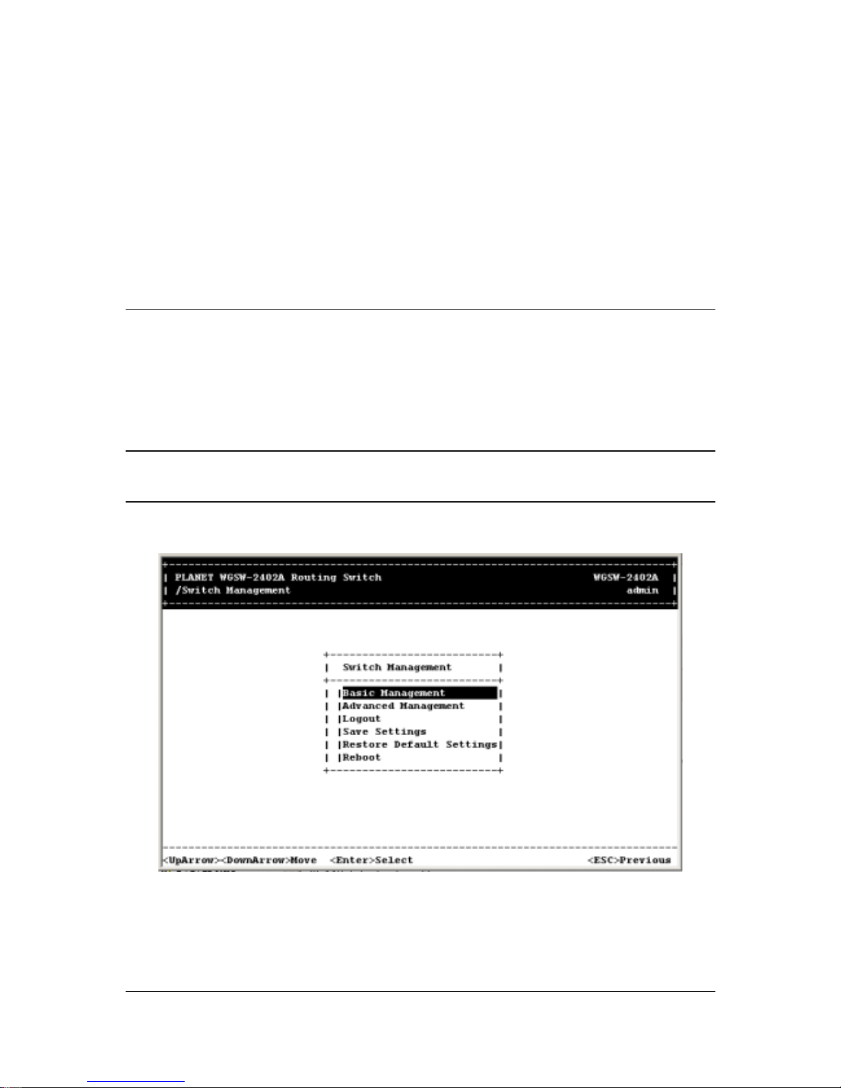
4.1 Logging on to the Switch
Enter the console interface factory default console name “admin” without password (or enter a
user-defined pass-word if you changed the factory default password). The Switch Management screen
in Figure 4-1 appears, with the Basic option highlighted.
Note:
Only one console and three telnet-users can log on to the Switch concurrently. However, it is
not recommended that multiple users modify the configuration at the same time.
F
IGURE
4-1 S
WITCH MANAGEMENT SCREEN
To perform basic management activities, see Section 4.3 “Performing Basic Management
Activities”.
To perform advanced management activities, see Section 5 “Performing Advanced Management
Activities”.
Page 29

- 21 -
To log out, highlight Logout and press Enter.
To save the current settings and remain in the configuration program, highlight Save Settings,
press Enter.
To restore the factory default settings, highlight Restore Default Settings and press Enter.
To reboot, highlight Reboot and press Enter.
4.2 Navigating Through the Console Interface
The console interface consists of a series of menu boxes. Each menu box has several options, which
are listed vertically. A highlight in each box lets you select the option you wish to choose; pressing the
Enter key activates the highlighted option. Table 4-1 shows the keys used for navigating through the
console interface.
T
ABLE
4-1 N
AVIGATING THROUGH THE CONSOLE INTERFACE
To... Press This Key...
Move the highlight one line up in a menu box. Up arrow or K
Move the highlight one line down in a menu box. Down arrow or J
Move the highlight between screens. Tab
Select the highlighted option. Enter
Move to the previous menu. Escape
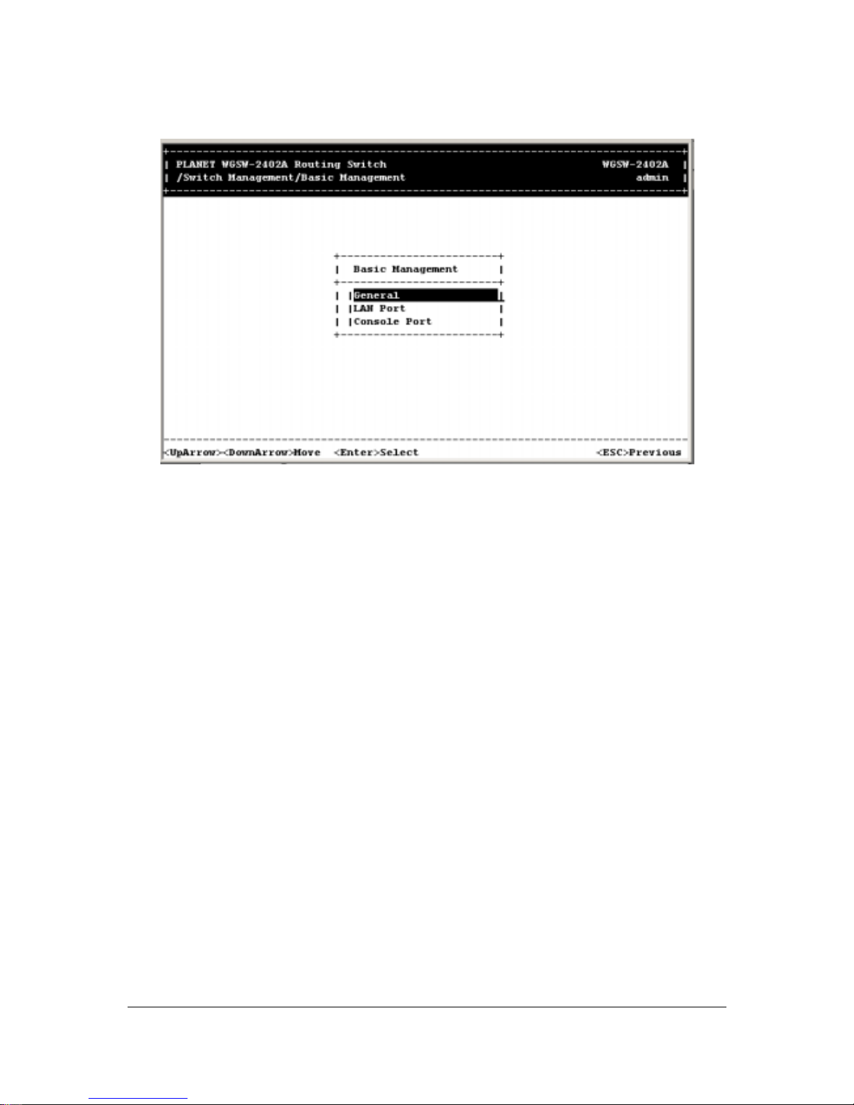
4.3 Performing Basic Management Activities
Basic management activities consist of General, LAN port, and console port tasks. To perform basic
management activities:
1. From the Switch Management screen (see Figure 4-1), highlight Basic Management and press
Enter. The Basic Management screen in Figure 4-2 appears.
Page 30
- 22 -
F
IGURE
4-2 B
ASIC MANAGEMENT SCREEN
2. From the Basic Management screen, highlight the desired option and press the Enter key:
General lets you change the system name, location, administration and guest passwords,
statistics collection, reboot-on-error, and remote Telnet login capability. See Section 4.3.1
“General Management Configuration”.
LAN Port lets you configure speed and flow control, link type, and physical address. See
Section 4.3.2 “LAN Port Configuration”.
Console Port lets you change the console baud rate, flow control method, modem control,
and modem setup string; enable or disable SLIP; and configure the SLIP address and SLIP
subnet mask. See Section 4.3.3 “Console Port Configuration”.
4.3.1 General Management Configuration
If you select General from the Basic Management screen (see Figure 4-2), the General screen in
Figure 4-3 appears, with the System Name value highlighted.
Page 31

- 23 -
F
IGURE
4-3 G
ENERAL SCREEN
Use the following procedure to configure the general management options.
4.3.1.1 Changing the System Name
To change the system name:
1. From the General screen, highlight System Name and press the Enter key. The Enter System
Name screen appears.
Page 32

- 24 -
F
IGURE
4-4 E
NTER SYSTEM NAME
2. Enter a system name. If you make a mistake, use the Backspace key to delete the error.
3. Press Enter to return to the General screen.
4.3.1.2 Changing the Contact and Location
To change the Contact and location:
1. Press the Down Arrow key to highlight Contact or Location and press the Enter key. The following
screen appears.
Page 33

- 25 -
F
IGURE
4-5 E
NTER CONTACT AND LOCATION
2. Enter a contact or location name. If you make a mistake, use the Backspace key to delete the
error.
3. Press Enter to return to the General screen.
4.3.1.3 Changing the Administration Password
To change the administration password:
1. Use the Down Arrow key to highlight admin Password and press the Enter key. The Enter Old
Password screen appears.
Page 34

- 26 -
F
IGURE
4-6 E
NTER OLD PASSWORD
2. Enter the current password. Each character you type appears as an asterisk (*). If you make a
mistake, use the Backspace key to delete the error.
3. Press Enter. The Enter New Password screen appears.
F
IGURE
4-7 E
NTER NEW PASSWORD
4. Enter the new password. For security, each password character you type appears as an asterisk
(*).
Page 35

- 27 -
5. Press Enter. A screen prompts you to reenter the new password.
F
IGURE
4-8 R
EENTER NEW PASSWORD
6. Reenter the new password you typed in step 4 and press Enter. The “Password changed”
message appears, confirming that the new password is in effect.
7. Press Enter to remove the message and return to the General screen. The admin password
appears as asterisks in the admin Password field.
Note: If the confirmation message does not appear, you may have typed the new password differently
in steps 4 and 6. In this case, your new password did not take effect. Repeat this procedure,
making sure to type the same new password in steps 4 and 6.
It is recommended to change the password and keep the new password in a safe place for a
secured management.
4.3.1.4 Changing the Guest Password
To change the guest password:
1. Use the Down Arrow key to highlight guest Password and press the Enter key. The Enter New
Password screen appears.
Page 36

- 28 -
F
IGURE
4-9 E
NTER NEW PASSWORD
2. Enter a new guest password. If you make a mistake, use the Backspace key to delete the error.
3. Press Enter to return to the General screen.
4.3.1.5 Statistic Collection
The statistic collection function allows the Switch to collect RMON and interface statistic data of each
port. To enable or disable Statistic Collection to the Switch:
1. From the General screen, highlight Statistic Collection and press the Enter key. The following
screen appears.
Page 37

- 29 -
F
IGURE
4-10 S
TATISTICS COLLECTION OPTIONS
2. Highlight one of the following choices:
Disabled — prevents statistic collection to the Switch.
Enabled — allows statistic collection to the Switch.
3. Press Enter to return to the General screen.
4.3.1.6 Reboot-On-Error
To enable or disable Reboot-On-Error to the Switch:
1. From the General screen, highlight Reboot-On-Error and press the Enter key. The following screen
appears.
Page 38

- 30 -
F
IGURE
4-11
2. Highlight one of the following choices:
Disabled — prevents the Switch to automatically reset when a fatal error is detected. This setting
is useful when a persistent problem needs to be reported.
Enabled — allows the Switch to automatically reset when a fatal error is detected.
3. Press Enter to return to the General screen.
4.3.1.7 Telnet Logins
To enable or disable Telnet logins to the Switch:
1. From the General screen, highlight Remote Telnet Login and press the Enter key. The following
screen appears.
Page 39

- 31 -
F
IGURE
4-12 R
EMOTE TELNET LOGIN OPTIONS
2. Highlight one of the following choices:
Disabled prevents remote Telnet logins to the Switch.
Enabled allows remote Telnet logins to the Switch. This is the default setting.
3. Press Enter to return to the General screen.
4.3.1.8 Remote Http Login
To enable or disable the function of Remote Http Login:
1. From the General screen, highlight Remote Http Login and press the Enter key. The following
screen will appear:
Page 40

- 32 -
F
IGURE
4-13 R
EMOTE
HTTP L
OGIN OPTIONS
2. Highlight one of the following choices:
Disable prevents remote HTTP login to the Switch.
Enable allows remote HTTP login to the Switch.
3. Press Enter to go back to the General screen.
4.3.1.9 Returning to the Basic Management Screen
After completing the general management activities, press the Esc key to exit the General screen and
return to the Basic Management screen in Figure 4-2. Select another option from the Basic
Management screen or press Esc to return to the Switch Management screen.
4.3.2 LAN Port Configuration
If you select LAN Port from the Basic Management screen (see Figure 4-2), the LAN Port
Configurations screen in Figure 4-14 appears, with Speed & Flow Control highlighted.
Page 41

- 33 -
F
IGURE
4-14 LAN P
ORT CONFIGURATIONS SCREEN
Use the procedures in the following sections to configure the LAN port configuration options for one or
more ports:
Speed & Flow Control - see Section 4.3.2.1 “Changing the Speed and Flow Control”.
Physical Address - see Section 4.3.2.2 “Displaying a Physical Port Address”.
4.3.2.1 Changing the Speed and Flow Control
To change the line speed and flow control for one or more ports:
1. From the LAN Port Configurations screen, highlight Speed & Flow Control and press the Enter key.
A screen similar to the following shows the current line speed settings for all ports.
Note: If there are more ports below the bottom one shown in a screen, a v appears next to the bottom
port in the screen (Port 12 in the following screen, for example). To view these ports, scroll the
highlight to the bottom port shown and press the Down Arrow key.
Page 42

- 34 -
F
IGURE
4-15
2. To configure an individual port, highlight the port and press the Enter key. The Speed & Flow Cntl
Options screen appears with the parameters for the port you selected.
F
IGURE
4-16 P
ORT SETTING OPTIONS
3. To change the line speed setting:
a. Press Enter with the Line Speed value highlighted. The following Speed Options menu
appears.
Page 43

- 35 -
F
IGURE
4-17 S
PEED
& F
LOW CONTROL OPTIONS
b. Highlight the line speed option you want to select for the port.
Auto allows the Switch to automatically ascertain the line speed and duplex mode.
All the other selections force the Switch to use a specific line speed and duplex mode.
Note: In the Speed Options screen, HD denotes half-duplex and FD denotes full-duplex. In addition,
1000M fiber ports have only Auto and 1000M/FD as selections, while 1000M copper ports have
Auto, 1000M/FD, 100M/FD and 10M/FD options.
c. Press Esc. You return to the Speed & Flow Cntl Options screen and the line speed setting you
selected appears next to Line Speed.
4. To configure the flow control for this port:
a. Press the Down Arrow key to highlight Flow Control and press Enter. The Flow Cntl Options
screen appears.
Page 44

- 36 -
F
IGURE
4-18 F
LOW CONTROL
b. Highlight the flow control option you want to select for the port.
Auto allows the Switch to automatically ascertain whether or not to use flow control.
On enables flow control at all times.
Off disables flow control at all times.
c. Press Esc. You return to the Speed & Flow Cntl Options screen and the flow control setting
you selected appears next to Flow Control.
5. Press Esc to remove the Speed & Flow Cntl Options screen.
6. To configure the line speed and flow control for additional ports, repeat steps 1 through 5.
7. When you finish, press the Esc key from the Line Speed & Flow Control screen to return to the LAN
Port Configurations screen.
4.3.2.2 Hiding or Displaying the Port Column
The Line Speed & Flow Control screen has a column between the port number and speed columns that
shows the port designations on the Switch. In this column, the Switch’s 10/100M ports are designated
by the numbers 1 through 24, while the Switch’s 1000M ports are designated by the letters A and B.
Page 45

- 37 -
F
IGURE
4-19
Using the L key, you can toggle this column so it is either displayed or hidden. By default, it is displayed.
To hide it, press the L key. To redisplay it, press the L key again.
4.3.2.3 Displaying a Physical Port Address
The following procedure describes how to display a physical port address.
1. From the LAN Port Configurations screen, highlight Physical Address and press the Enter key. A
screen similar to the following appears.
Note: This screen also lets you use the L key to toggle the Port column, as described under Section
4.3.2.2 “Hiding or Displaying the Port Column”.
Page 46

- 38 -
Figure 4-20
2. Use the Up Arrow and Down Arrow keys to scroll up and down the list.
3. When you finish, press the Esc key to return to the LAN Port Configurations screen.
4.3.2.4 Returning to the Basic Management Screen
After completing the LAN port configuration activities, press the Esc key to exit the LAN Port
Configurations screen and return to the Basic Management screen. Select another option from the
Basic Management screen or press Esc to return to the Switch Management screen.
4.3.3 Console Port Configuration
If you select Console Port from the Basic Management screen, the Console Port Configurations
screen in Figure 4-21 appears, with the Baud Rate value highlighted.
Page 47

- 39 -
F
IGURE
4-21 C
ONSOLE PORT CONFIGURATIONS SCREEN
Use the procedures in the following sections to configure the Console Port Configuration options for
one or more ports:
To change the console baud rate, see section 4.3.3.1 “Changing the Console Baud Rate”.
To change the console flow control setting, see section 4.3.3.2 “Selecting a Flow Control Method”.
To enable or disable a console modem connection, see section 4.3.3.3 “Enabling or Disabling
Modem Control Options”.
To specify a modem setup string, see section 4.3.3.4 “Specifying a Modem Setup String”.
To enable or disable SLIP, see section 4.3.3.5 “Enabling or Disabling SLIP”.
To specify a SLIP address, see section 4.3.3.6 “Specifying a SLIP Address”.
To specify a SLIP subnet mask, see section 4.3.3.7 “Specifying a SLIP Subnet Mask”.
4.3.3.1 Changing the Console Baud Rate
To change the console baud rate:
1. From the Console Port Configurations screen, highlight Baud Rate and press the Enter key. A
screen similar to the following shows the current console baud rate.
Page 48

- 40 -
F
IGURE
4-22
2. Highlight the baud rate you want to select for the console:
Auto allows the Switch to auto-baud between 9600 bps and 115,200 bps. If you choose this
selection, choose the rest of your configuration selections. Then, when you exit the
configuration program, press the Enter key one or more times until the Switch Login Password
appears on your computer screen.
All the other selections force a specific console baud rate.
3. Press Enter. You return to the Console Port Configurations screen and the console port baud rate
you selected appears in the Baud Rate field.
4.3.3.2 Selecting a Flow Control Method
To change the console flow control used:
1. From the Console Port Configurations screen, highlight Flow Control and press the Enter key. A
screen similar to the following shows the current console flow control method.
Page 49

- 41 -
F
IGURE
4-23
2. Highlight the flow control method you want to select for the console and press Enter. You return to
the Console Port Configurations screen and the console port flow control method you selected
appears in the Flow Control field.
4.3.3.3 Enabling or Disabling Modem Control Options
To enable or disable modem control options for the console port:
1. From the Console Port Configurations screen, highlight Modem Control and press the Enter key. A
screen similar to the following shows whether a console modem connection is enabled or disabled.
Page 50

- 42 -
F
IGURE
4-24
2. Highlight whether you want to enable or disable a modem connection to the console port.
3. Press Enter. You return to the Console Port Configurations screen and the modem control option
you selected appears in the Modem Control field.
Note: If you enable a modem connection, proceed to section 4.3.3.4 “Specifying a Modem Setup
String” to specify the appropriate modem setup string.
4.3.3.4 Specifying a Modem Setup String
If you enabled a modem connection to the console port, use the following procedure to specify a
modem setup string:
1. From the Console Port Configurations screen, highlight Modem Setup String and press the Enter
key. A screen similar to the following shows the current modem setup string option.
Page 51

- 43 -
F
IGURE
4-25
2. Highlight whether you want to use the default setup string or a custom setup string.
3. Press the Enter key.
If you highlight Default Setup String, you return to the Console Port Configurations screen and
the default modem string appears in the Modem Setup String field.
If you highlight Custom Setup String, enter the custom string in the Enter Modem Setup String
screen and press Enter again. You return to the Console Port Configurations screen and the
custom setup string appears in the Modem Setup String field.
Note: The default modem setup string configures the modem to auto answer. It works for all Hayes
compatible modems.
4.3.3.5 Enabling or Disabling SLIP
To enable or disable SLIP:
1. From the Console Port Configurations screen, highlight SLIP and press the Enter key. A screen
similar to the following shows the current SLIP setting.
Page 52

- 44 -
F
IGURE
4-26
Highlight whether you want SLIP enabled or disabled and press Enter. You return to the Console Port
Configurations screen and the SLIP option you selected appears in the SLIP field.
Note: If you enable SLIP, a message tells you that the console port becomes accessible only through
the SLIP protocol after you logout from the current console screen. To access the Switch,
configure your PC to use SLIP, then use Telnet to interface with the Switch. If you use
HyperTerminal, enabling SLIP and saving your selections displays the following screen, giving
the impression that the Switch has “hung” when it is actually still operating. This occurs because
HyperTerminal does not support SLIP. However, you can still access the Switch using Telnet, as
described in the paragraph above.
Page 53

- 45 -
F
IGURE
4-27
If you enable SLIP, specify a SLIP address and subnet mask (see “Specifying a SLIP Address” and
“Specifying a SLIP Sub-net Mask”).
4.3.3.6 Specifying a SLIP Address
If you enabled SLIP, use the following procedure to enter an address that has a network part different
than the network address of the Switch. (For more information, contact your network administrator.)
1. From the Console Port Configurations screen, highlight SLIP Address and press Enter. The
following screen appears.
Page 54

- 46 -
F
IGURE
4-28
2. Enter the SLIP address. The address consists of numbers separated by periods. For example:
129.32.0.11
3. After you enter the SLIP address, press the Enter key. You return to the Console Port
Configurations screen and your entry appears in the SLIP Address field.
4.3.3.7 Specifying a SLIP Subnet Mask
If you are using SLIP, enter a suitable SLIP subnet mask.
1. From the Console Port Configurations screen, highlight SLIP Subnet Mask and press Enter. The
Enter IP Subnet Mask screen appears. You must enter a SLIP address before you can enter a
SLIP subnet mask.
Page 55

- 47 -
F
IGURE
4-28
2. Enter the SLIP subnet mask. The subnet mask consists of numbers separated by periods. For
example: 255.255.255.0
3. After you enter the SLIP subnet mask, press the Enter key. You return to the Console Port
Configurations screen and your entry appears in the SLIP Subnet Mask field.
4.3.3.8 Returning to the Basic Management Screen
After completing the general management activities, press the Esc key to exit the Console Port
Configurations screen and return to the Basic Management screen in Figure 4-2. Select another option
from the Basic Management screen or press Esc to return to the Switch Management screen.
Page 56

- 48 -
Chapter 5 Performing Advanced Management
Activities
Advanced management activities consist of the L2 switching database, IP Networking, bridging, static
filtering, spanning tree, SNMP, other protocols (GVRP and IGMP), Port Trunking, port mirroring, QoS
Setup and File Transfer. To perform advanced management activities:
1. From the Switch Management screen (see Figure 4-1), highlight Advanced Management and press
Enter. The Advanced Management screen in Figure 5-1 appears.
F
IGURE
5-1 A
DVANCED MANAGEMENT SCREEN
2. From the Advanced Management screen, highlight the desired option and press the Enter key:
L2 Switching DataBase — lets you view and change VLAN, PVID, MAC address, IP
multicast group, MAC address, and port perspectives. See section 5.1 “Switching Database
Configuration”.
IP Networking — lets you view or change IP settings, ARP and routing table parameters,
DHCP gateway settings, and ping settings. See section 5.6 “IP Networking”.
Bridging — lets you view and change the aging period for a MAC address and the flood
limit for all ports. See section 5.7 “Bridging”.
Static Filtering — lets you view, add, delete, or search all source or destination MAC
addresses to be filtered. See section 5.8 “Static Filtering”.
Spanning Tree — lets you view and change spanning tree configurations, port states, path
costs, and port priorities. See section 5.9 “Spanning Tree Functions”.
Page 57

- 49 -
SNMP — lets you view and change the SNMP configuration. See section 5.10 “SNMP
Functions”.
Other Protocols — lets you view and change GVRP and IGMP settings. Refer to section
5.11 “Other Protocols”.
Port Trunking — lets you assign a range of ports to trunking groups. Refer to section 5.12
“Port Trunking”.
Port Mirroring — lets you mirror one port to another. Refer to section 5.13 “Port Mirroring”.
QoS Setup — lets you specify Quality of Service parameters. Refer to section 5.14 “Setting
Quality of Service Parameters”.
File Transfer — lets you send files using the TFTP or Kermit protocol. See section 5.15
“Sending and Receiving Files”.
5.1 Switching Database Configuration
If you select L2 Switching DataBase from the Advanced Manage m ent screen (see Figure 4-5), the L2
Switching DataBase screen in Figure 5-2 appears, with VLAN & PVID Perspective highlighted.
Page 58

- 50 -
F
IGURE
5-2 L2 S
WITCHING DATABASE SCREEN
The Switch can be viewed from the four perspectives in the L2 Switching DataBase screen in Figure
5-2:
VLAN & PVID Perspective see section 5.2 “VLAN & PVID Perspective”.
IP Multicast Group Perspective — see section 5.3 “IP Multicast Group Perspective”.
MAC Address Perspective see section 5.4 “MAC Address Perspective”.
Port Perspective see section 5.5 “Port Perspective”.
These four views allow a network administrator to manage and monitor VLANs and their associated
MAC addresses and ports effectively from different views.
5.2 VLAN & PVID Perspective
Packets received by the Switch will be treated in the following way with regard to the Switch's VLAN
settings:
1. When an untagged packet enters a port, it will be automatically tagged with the port's VLAN ID tag
number. Each port has a default VLAN ID setting which is user configurable (the default setting is
1). The default VLAN ID setting for each port can be changed in the PVID settings of console or
web.
2. When a tagged packet enters a port, the tag for that packet will be unaffected by the PVID Setting.
3. The packet will now proceed to the VLAN specified by it's VLAN ID tag number.
Page 59

- 51 -
4. If the port in which the packet entered does not have membership with the VLAN specified by the
packets VLAN ID tag, the packet will be dropped. Port VLAN membership settings are changed in
the VLAN settings page.
5. If the port has membership to the VLAN specified by the packet's VLAN ID, the packet will be able
to be sent to other ports with the same VLAN ID membership.
6. Packets leaving the Switch will be either tagged or untagged depending on the setting specified
for that port’s membership properties.
The following sections describe the default VLAN, how to obtain a VLAN perspective and how to set the
PVID. For more information regarding to VLAN, please refer to appendix for more detail.
5.2.1 Default VLAN
The IEEE 802.1q standard defines VLAN ID #1 as the default VLAN. The default VLAN includes all the
ports as the factory default. The default VLAN’s egress rule restricts the ports to be all untagged, so it
can, by default, be easily used as a simple 802.1d bridging domain. The default VLAN’s domain shrinks
as untagged ports are defined in other VLANs.
5.2.2 Obtaining a VLAN Perspective
The following procedure describes how to obtain a VLAN perspective. For convenience, the VLAN ID
appears as both decimal and hexadecimal values side by side in the VLAN perspective screen.
1. From the L2 Switching DataBase screen in Figure 5-2, highlight VLAN & PVID Perspective and
press the Enter key. Highlight VLAN Settings and pres the Enter key. A VLAN perspective screen
similar to the one in Figure 5-3 appears.
Page 60

- 52 -
F
IGURE
5-3 VLAN P
ERSPECTIVE SCREEN
2. From this screen you can:
Create a new VLAN. See section 5.2.2.1 “Creating a New VLAN”.
Delete a VLAN ID. See section 5.2.2.2 “Deleting a VLAN ID”.
View VLAN activities. See section 5.2.2.3 “Viewing VLAN Activities”.
View or change a VLAN configuration. See section 5.2.2.4 “Viewing VLAN Settings”.
Return to the L2 Switching Database screen by pressing Esc.
5.2.2.1 Creating a New VLAN
To create a new VLAN:
1. From the VLAN Perspective screen in Figure 5-4, hold down the Shift key and press the + key. The
New VLAN Settings screen appears.
Page 61

- 53 -
F
IGURE
5-4 N
EW
VLAN S
ETTINGS SCREEN
2. With the highlight in the VLAN ID field, press the Enter key. The Enter New VLAN ID screen
appears.
F
IGURE
5-5
3. Enter a new VLAN ID as between 2 ~ 4094 value.
4. Press Enter. The VLAN ID appears next to VLAN ID in the New VLAN Settings screen.
Page 62

- 54 -
Note: “Remote” is appended to the VLAN ID automatically if the VLAN is learned from a remote switch.
5. To enter an optional VLAN name, perform the following steps. Note that the VLAN name is used to
identify the VLAN at the local switch.
a. Press the Down Arrow key to highlight VLAN Name.
b. Press Enter. The Enter New VLAN Name screen appears.
F
IGURE
5-6
c. Enter a name for the new VLAN.
d. Press Enter. The VLAN name appears next to VLAN Name in the New VLAN Settings
screen.
6. Press the Esc key. A screen similar to the following appears.
Page 63

- 55 -
F
IGURE
5-7
This screen lets you:
Add switch ports to a VLAN. See section 5.2.2.2 “Adding New Switch Ports”.
Delete switch ports from a VLAN. See section 5.2.2.3 “Deleting a VLAN ID”.
5.2.2.2 Adding New Switch Ports
To add new switch ports to the newly created VLAN:
1. Hold down the Shift key and press + to display the Port Options screen.
Page 64

- 56 -
F
IGURE
5-8
2. In the Port Options screen, highlight Untagged Ports, Tagged Ports, or Forbidden Ports and
press the Enter key. If you highlight Untagged Ports, the screen window reads Select Untagged
Ports, as in the following figure.
F
IGURE
5-9
If you highlight Tagged Ports, the screen window reads Select Tagged Ports, as in the following
figure.
Page 65

- 57 -
F
IGURE
5-10
If you highlight Forbidden Ports, the screen window reads Select Forbidden Ports, as in the following
figure.
F
IGURE
5-11
3. In the Select Untagged Ports, Select Tagged Ports, or Select Forbidden Ports screen, use the
Up Arrow and Down Arrow keys to highlight an individual port.
Page 66

- 58 -
4. Press Enter. An asterisk appears to the right of the port to show it is selected, as in the following
figure. Repeat this step for each new port you want to add.
Note: As a convenience, you can highlight All Ports to select all of the ports at one time.
F
IGURE
5-12
5. After selecting the new ports you want to add, press Esc. A screen shows the ports you selected
and whether they are tagged, untagged, or forbidden. For example:
Page 67

- 59 -
F
IGURE
5-13
6. If you added untagged ports and want to now add tagged ports or forbidden ports, or vice versa,
repeat steps 1 through 5 and in step 2 select the appropriate port option.
Note: To delete a switch port in the screen above, highlight the port and press the - (hyphen) key. A
precautionary prompt does not appear before you delete a switch port, so be sure you do not
need the port before you delete it. You can also hold down the Shift key and press + to add
ports.
7. Press Esc to return to the VLAN Perspective screen. The VLAN IDs and names you added appear
in the VLAN Perspective screen. In the screen on the next page, for example, the “planet” VLAN
have been added.
Note: To change a port’s property, first delete the port; then add the port with the new property.
8. Select another option from the VLAN Perspective screen or press Esc to return to the L2 Switching
DataBase screen.
Page 68

- 60 -
F
IGURE
5-14
5.2.2.3 Deleting a VLAN ID
To delete a VLAN ID from the VLAN Perspective screen:
1. Use the Up Arrow and Down Arrow keys to highlight the VLAN ID you want to delete.
2. Press the - (hyphen) key. A precautionary message asks whether you are sure you want to delete
the VLAN ID.
Page 69

- 61 -
F
IGURE
5-15
3. With Yes highlighted, press the Enter key to delete the VLAN ID. Or to retain it, press the Esc key
or highlight No and press Enter.
5.2.2.4 Viewing VLAN Activities
The following procedure describes how to use the VLAN Perspective screen to view activities for a
particular VLAN. Using this procedure, you can view:
Active ports.
Active MAC addresses associated with a VLAN.
A transient address, if any.
Filtering and port information.
To view VLAN activities:
1. From the VLAN Perspective screen in, highlight an existing VLAN and press the Enter key. The
VLAN Info screen appears, with the highlight on VLAN Activities.
Page 70

- 62 -
F
IGURE
5-16
2. Press the Enter key. A screen similar to the following appears.
F
IGURE
5-17
This screen shows all active VLAN domains for the VLAN you selected. You can use the Up Arrow and
Down Arrow keys to scroll through the list of domains associated with the selected VLAN. When you
finish performing VLAN activities, press the Esc key until you return to the desired screen.
Page 71

- 63 -
5.2.2.5 Viewing VLAN Settings
Using the VLAN Configuration screen, you can view VLAN settings.
1. From the VLAN Perspective screen, highlight an existing VLAN and press the Enter key. A screen
similar to the following appears, with the highlight on VLAN Activities.
F
IGURE
5-18
2. Press the Up or Down Arrow key to highlight VLAN Settings.
3. Press Enter. A screen similar to the following appears.
Page 72

- 64 -
F
IGURE
5-19
4. From this screen, you can add switch ports to or delete them from any VLAN except the default
VLAN. The controls for adding and deleting ports do not display for the default VLAN.
5.2.2.6 Adding Ports
To add ports to a VLAN:
1. From the screen above, hold down the Shift key and press +. The Port Options screen appears.
Page 73

- 65 -
F
IGURE
5-20
2. Select either untagged or tagged ports. To select untagged ports:
a. Highlight Untagged Ports and press Enter. The Select Untagged Ports screen appears, with
a list of the untagged ports that are not in use. Initially, there are 16 untagged ports you can
select; this number decreases as you use untagged ports in your VLANs.
F
IGURE
5-21
b. To configure an individual port, highlight it and press Enter. An asterisk appears next to each
Page 74

- 66 -
port you select. (To deselect it, press Enter again to remove the asterisk.)
To configure all ports, highlight All Ports and press Enter.
c. Press Esc. The port(s) you selected appear in the previous screen.
To select tagged ports:
a. Highlight Tagged Ports and press Enter. The Select Tagged Ports screen appears, with a list
of the tagged ports.
F
IGURE
5-22
b. To configure an individual port, highlight it and press Enter. An asterisk appears next to each
port you select. (To deselect it, press Enter again to remove the asterisk.)
To configure all ports, highlight All Ports and press Enter.
c. Press Esc. The port(s) you selected appear in the previous screen.
Note: Even though you have specified the port to be tagged port for the VLAN ID, the Switch
will still untagged the packets if the PVID setting is the same as the VLAN ID. It is
strongly recommended to organize your VLANs and different switches while setting
up the network.
To select forbidden ports:
a. Highlight Forbidden Ports and press Enter. The Select Forbidden Ports screen appears,
with a list of the tagged ports.
Page 75

- 67 -
F
IGURE
5-23
b. To configure an individual port, highlight it and press Enter. An asterisk appears next to each
port you select. (To deselect it, press Enter again to remove the asterisk.)
To configure all ports, highlight All Ports and press Enter.
c. Press Esc. The port(s) you selected appear in the previous screen.
3. When you finish, press Esc until you return to the desired screen.
5.2.2.7 Deleting Ports
The following procedure describes how to delete ports from a VLAN. There is no precautionary
message that appears before you delete a VLAN port, so be sure you want to delete the port before
doing so.
1. From the screen, use the Up and Down Arrow keys to highlight the port you want to delete.
2. Press the - (hyphen) key. The port is deleted.
3. When you finish, press the Esc key until you return to the desired screen.
5.2.3 Configuring PVID
The PVID provides identification to the port of VLAN. The Switch will tag with this ID to any incoming
Page 76

- 68 -
VLAN-untagged packets. The switch will also un-tag the VLAN ID from outgoing packets if the port’s
PVID is the same as the outgoing packet’s VLAN ID. If you want to configure the PVID, highlight PVID
setting from the VLAN & PVID Perspective screen and press Enter. The following screen will appear:
F
IGURE
5-24
The following steps will show you how to set the PVID.
1. Highlight an individual port you want to configure and press Enter. The Enter New PVID column
will appear next to PVID Settings screen.
F
IGURE
5-25
Page 77

- 69 -
2. Enter a decimal number in the Enter New PVID column. Then press Enter.
F
IGURE
5-26
Note: Even though you have specified the port to be tagged port for the VLAN ID, the Switch will still
untagged the packets if the PVID setting is the same as the VLAN ID. If your network is with
multiple switches, organize the VLAN groups before setting up the VLAN ID of the ports.
5.3 IP Multicast Group Perspective
The Internet Group Management Protocol (IGMP) runs between hosts and their immediately
neighboring multicast routers. The protocol’s mechanisms allow a host to inform its local router that it
wants to receive transmissions addressed to a specific multicast group.
Routers periodically query the LAN to determine if known group members are still active. If there is
more than one router on the LAN performing IP multicasting, one of the routers is elected “querier” and
assumes the responsibility of querying the LAN for group members. Based on the group membership
information learned from the IGMP, a router can determine which (if any) multicast traffic needs to be
for-warded to each of its “leaf” subnetworks. Multicast routers use this information, along with a
multicast routing protocol, to support IP multicasting across the Internet.
Page 78

- 70 -
IGMP provides the final step in an IP multicast packet delivery service since it is only concerned with
the forwarding of multicast traffic from the local router to group members on directly attached
subnetworks. The Switch support IP Multicast Filtering by:
Passively snooping on the IGMP Query and IGMP Report packets transferred between IP
Multicast Routers and IP Multicast host groups to learn IP Multicast group members, and
Actively sending IGMP Query messages to solicit IP Multicast group members.
The purpose of IP multicast filtering is to optimize a switched network's performance, so multicast
packets will only be forwarded to those ports containing multicast group hosts members and routers
instead of flooding to all ports in the subnet (VLAN).
The Switch with IP multicast filtering/switching capability not only passively monitor IGMP Query and
Report messages, DVMRP Probe messages, PIM, and MOSPF Hello messages; they also actively
send IGMP Query messages to learn locations of multi-cast routers and member hosts in multicast
groups within each VLAN.
Note, however, IGMP neither alters nor routes any IP multicast packets. Since IGMP is not concerned
with the delivery of IP multicast packets across subnets, an external IP multicast router is needed if IP
multicast packets have to be routed across different subnets.
The IP multicast group perspective provides information associated with an IP multicast group. To
obtain an IP multicast group perspective:
1. From the L2 Switching DataBase screen, highlight IP Multicast Group Perspective and press the
Enter key. A screen similar to the following appears.
Page 79

- 71 -
F
IGURE
5-27
Note: If IGMP is disabled, the message IGMP Currently Disabled appears instead of the screen
above. To correct this, use Other Protocols in the Advanced Management menu to set IGMP to
either Passive or Active (see “Other Protocols”)
2. To obtain an IP multicast group perspective for one of the addresses in the screen above, use the
Up and Down Arrow keys to highlight an address and press the Enter key. A screen similar to the
following appears.
Page 80

- 72 -
F
IGURE
5-28
3. To view the VLAN and IP multicast group addresses associated with the MAC address, highlight a
host in the Hosts screen and press Enter. A VLAN/IP Multicast Group Membership screen similar
to the following appears.
F
IGURE
5-29
4. Use the Up and Down Arrow keys to scroll through the VLAN/IP Multicast Group Membership
screen.
Page 81

- 73 -
5. When you finish, press Esc until you return to the desired screen.
5.4 MAC Address Perspective
The MAC address perspective lets you view all characteristics associated with a MAC address,
corresponding VLANs, and corresponding ports in the Switching database.
To obtain a MAC address perspective:
1. From the L2 Switching DataBase screen, highlight MAC Address Perspective and press the Enter
key. You are prompted for a MAC address.
F
IGURE
5-30
2. Enter the MAC address whose characteristics, corresponding VLANs, and corresponding ports you
want to view.
3. Press Enter. A screen similar to the following appears.
Page 82

- 74 -
F
IGURE
5-31
4. Use the Up and Down Arrow keys to scroll through the VLAN/IP Multicast Group Membership
screen.
5. When you finish, press the Esc key to return to the desired screen.
5.5 Port Perspective
The port perspective lets you view VLAN activities port statistics, and per-port MAC limits. To obtain a
port perspective:
1. From the L2 Switching Database screen, highlight Port Perspective and press the Enter key. The
following Port Perspective screen appears.
Page 83

- 75 -
F
IGURE
5-32
2. To view per-port VLAN activities, highlight Per Port VLAN Activities, press the Enter key, and
proceed to section 5.5.1.
3. To view per-port statistics, highlight Per Port Statistics, press the Enter key, and proceed to section
5.5.2.
5.5.1 Per Port VLAN Activities
This option allows you to view MAC address and VLAN on selected port. If you select Per Port VLAN
Activities from the Port Perspective screen, a screen similar to the following Per Port VLAN Activities
appears.
Page 84

- 76 -
F
IGURE
5-33
1. Use the Up Arrow and Down Arrow keys to highlight the port number whose corresponding VLANs
activities you want to view.
2. Press the Enter key. A screen similar to the following appears, with a list of the MAC addresses for
the selected VLAN and the corresponding VLAN memberships.
F
IGURE
5-34
Page 85

- 77 -
5.5.2 Scrolling Through MAC Addresses
To scroll through the list of active MAC addresses corresponding to the selected port:
1. If the MAC Addresses screen is not the current screen, press the Tab key until it becomes the
current screen. The status bar at the bottom of the screen acquires the <Enter>View and
<s>Search functions.
2. Use the Up Arrow and Down Arrow key to scroll through the list of active MAC addresses for the
selected port.
3. To search for a MAC address, press S. When the search prompt appears, enter a MAC address in
the Enter MAC Addr to Search: screen and press the Enter key. If the address is found, it is
highlighted in the Port MAC Addresses screen.
4. To obtain additional information about a particular MAC address, scroll to the address in the Port
MAC Address screen and press the Enter key. Screens similar to the following appear, showing
detailed information about the selected MAC address.
F
IGURE
5-35
5.5.3 Hiding or Displaying the Port Column
The Per Port Statistics screen has a column between the port number and statistics columns that
shows the port designations on the Switch. In this column, the Switch’s 10/100M ports are designated
with the numbers 1 through 24, while the Switch’s expansion module ports are designated with the
Page 86

- 78 -
letters A and B.
F
IGURE
5-36
Using the L key, you can toggle this column so it is either displayed or hidden. By default, it is displayed.
To hide it, press the L key. To redisplay it, press the L key again.
5.5.4 Per Port Statistics
If you select Per Port Statistics from the Port Perspective screen, a screen similar to the following Per
Port Statistics appears.
Page 87

- 79 -
F
IGURE
5-37
1. To reset counters for all ports, press R. Then, when the following screen appears, highlight Yes
and press Enter to reset the counters, Or highlight No and press Enter to not reset them.
F
IGURE
5-38
2. To view statistics for a port, use the Up and Down Arrow keys to highlight the desired port, then
press the Enter key. A screen similar to the following appears, showing the statistics for the port
you selected.
Page 88

- 80 -
F
IGURE
5-39
3. To reset counters for the port in the screen above, press R. The following screen appears.
F
IGURE
5-40
4. With Yes highlighted, press the Enter key to reset the counters. Or to retain them, press the Esc
key or highlight No and press Enter.
Page 89

- 81 -
5.5.5 Per Port Mac Limit
This option allows you to specify the maximum number of MAC addresses on each port. If you select
Per Port MAC Limit from the Port Perspective screen, a screen similar to the following one appears.
F
IGURE
5-41
1. To specify MAC learning options for a MAC port, use the Up and Down Arrow keys to highlight a
port, then press the Enter key. A MAC Learning Options screen similar to the following appears.
F
IGURE
5-42
Page 90

- 82 -
2. Highlight the desired option, then press Enter.
3. If you selected Set Learning Limit, the Enter New Limit screen appears.
F
IGURE
5-43
4. Type the new limit, and press Enter.
5.5.6 Returning to the Advanced Management Screen
After completing the L2 switching database activities, press the Esc key to return to the Advanced
Management screen. Select another option from the Advanced Management screen or press Esc to
return to the Switch Management screen.
5.6 IP Networking
If you select IP Networking from the Advanced Management screen, the IP Networking screen in
Figure 5-44 appears.
Page 91

- 83 -
F
IGURE
5-44 IP N
ETWORKING SCREEN
From the IP networking screen, you can:
View or change IP and RIP settings. See section 5.6.1 “IP and RIP Settings”.
Add, delete, and search ARP table entries. See section 5.6.2 “ARP Table Setting”.
View, add, delete or search a particular routing path. See section 5.6.3 “Routing Table”.
Specify DHCP gateway settings. See section 5.6.4 “DHCP Gateway Settings”.
View or change ping settings. See section 5.6.5 “Ping Settings”.
5.6.1 IP and RIP Settings
If you select IP & RIP Settings from the IP Networking screen, a screen similar to the following
appears, with a list of the VLAN IDs, IP addresses, subnet masks, proxy ARPs, and RIPs currently
defined.
The Switch supports both static and dynamic routing.
Static routing requires routing information to be stored in the Switch, either manually or when a
connection is set up by an application outside the Switch.
Dynamic routing uses a routing protocol to exchange routing information, calculate routing tables,
and respond to changes in the status or loading of the network.
Dynamic routing involves the determination and updating of all the routing information required for
packet forwarding.
Handling routing protocols
Updating the routing table
The Switch supports RIP and RIP-2 dynamic routing protocols.
Page 92

- 84 -
The RIP protocol is the most widely used routing protocol. The RIP protocol uses a distance
vector-based approach to routing. Routes are determined on the basis of minimizing the distance
vector, or hop count, which serves as a rough estimate of transmission cost. Each router broadcasts its
advertisement every 30 seconds, together with any updates to its routing table. This allows all routers
on the network to learn consistent tables of next hop links which lead to relevant subnets. Just as Layer
2 switches use the Spanning Tree Algorithm to prevent loops, routers also use methods for preventing
loops that would cause endless retransmission of data traffic. RIP utilizes the following three methods
to prevent loops from occurring:
Split horizon— never propagate routes back to an interface port from which they have been
acquired.
Poison reverse— propagate routes back to an interface port from which they have been acquired,
but set the distance vector metrics to infinity. (This provides faster convergence.)
Triggered updates— whenever a route gets changed, broadcast an update message after waiting
for a short random delay, but without waiting for the periodic cycle.
RIP-2 is a compatible upgrade to RIP. RIP-2 adds useful capabilities for plain text authentication,
multiple independent RIP domains, variable length subnet masks, and multicast transmissions for route
advertising (RFC 1388).
There are several serious problems with RIP that you should consider before deciding which routing
protocol to use for your network. First of all, RIP (version 1) has no knowledge of subnets, both RIP
versions can take a long time to converge on a new route after the failure of a link or router during
which time routing loops may occur, and its small hop count limitation of 15 restricts its use to smaller
networks. Moreover, RIP (version 1) wastes valuable network bandwidth by propagating routing
information via broadcasts, nor does it consider enough network variables to make the best routing
decision.
Note: Before you can define a VLAN’s IP settings, you must first create a VLAN as described under
“Creating a New VLAN”.
Page 93

- 85 -
F
IGURE
5-45
To modify the settings shown:
1. Use the Down Arrow key to highlight the row that contains the parameters you want to change, and
then press Enter. A screen similar to the following appears, with the highlight in the IP Address
field.
The available options are:
IP Address: The IP address of the Switch for this VLAN.
IP Subnet Mask: The subnet mask of the IP.
Frame Type: Either Ethernet II or Ethernet SNAP. Default is Ethernet II.
BOOTP: Specify how the IP address of the Switch for this VLAN is assigned. Default is
None for manually configuring. You can also specify BOOTP or DHCP to get IP address.
Please note that you should setup a BOOTP server or DHCP server on this VLAN network.
Proxy ARP: When a node in the attached subnetwork does not have routing or a default
gateway configured, ARP Proxy can be used to forward an ARP request to a remote
subnetwork. When the Switch receives an ARP request for a remote network and ARP Proxy
is enabled, it determines if it has the best route to the remote network, and then answers the
ARP request by sending its own MAC address to the requesting node. That node then sends
traffic to the Switch, which in turn uses its own routing table to forward the traffic to the remote
destination. End stations that require Proxy ARP must view the entire network as a single
network. These nodes must therefore use a smaller subnet mask than that used by the Switch
or other relevant network devices.
RIP Setting: Disable RIP or use RIP-1 / RIP-2.
Page 94

- 86 -
Use Broadcast/Multicast: Specify how the routing table is sent out. RIP-1 can only use
broadcast. RIP-2 can use multicast to reduce network traffic.
Advertise Routes: Enable or disable the Switch to advertise its own routing table.
Advertise Default Route: Enable or disable the Switch to advertise its own default route.
Accept RIP V1/V2 Updates: Configure the Switch to accept routing table from other routers.
Enabling RIP-1 can only accept RIP-1 update but enabling RIP-2 can accept RIP-1, RIP-2 or
RIP-1/RIP-2 updates.
Use Split Horizon: This allows the Switch to never propagate routes back to an interface port
from which they have been acquired.
Use Poisoned Reverse: This allows the Switch to propagate routes back to an interface port
from which they have been acquired, but set the distance vector metrics to infinity.
Send Trigger Responses: If this configuration is Yes, whenever a route gets changed, the
Switch broadcast an update message after waiting for a short random delay, but without
waiting for the periodic cycle.
F
IGURE
5-46
2. Review the settings. To change a setting, highlight it, press the Enter key, select the desired setting,
and press Esc.
3. To delete a setting, highlight the setting and press the - (hyphen) key. When a message asks you
to confirm the deletion, highlight Yes and press Enter to delete it, or press Esc or highlight No and
press Enter to retain it.
4. When you finish, press the Esc key until you return to the desired screen.
Page 95

- 87 -
5.6.2 ARP Table Setting
If you select ARP Table from the IP Networking screen in Figure 5-47, an ARP Table screen similar to
the following appears with the ARP table entries that have been already defined or learned.
F
IGURE
5-47
From this screen, you can:
Add static entries to the ARP table. See section 5.6.2.1 “Adding Static ARP Table Entries”.
Delete static entries from the ARP table. See section 5.6.2.2 “Deleting Static ARP Table Entries”.
Search for entries in the ARP table. See section 5.6.2.3 “Searching for ARP Table Entries”.
5.6.2.1 Adding Static ARP Table Entries
To add static entries to the ARP table:
1. From the ARP Table screen, hold down the Shift key and press +. The Static ARP Specifications
screen appears, with the highlight in the Internet Address field.
Page 96

- 88 -
F
IGURE
5-48
2. Press the Enter key. The Enter Internet Address screen appears.
F
IGURE
5-49
3. Type an Internet address. The address consists of numbers separated by periods. For example:
203.70.249.5. When you finish, press Enter. The Internet address you typed appears next to
Internet Address in the Static ARP Specifications screen.
Page 97

- 89 -
4. Press the Down Arrow key to highlight Physical Address and press Enter. The Enter Physical
Address screen appears.
F
IGURE
5-50
5. Type the corresponding physical address and press Enter. The physical address you typed
appears next to Physical Address in the Static ARP Specifications screen.
6. Press Esc. The Internet and physical addresses you typed appear in the ARP Table screen. The
following screen shows an example of Internet and physical addresses that have been added.
Page 98

- 90 -
F
IGURE
5-51
7. To add more static ARP table entries, repeat steps 1 through 6. When you finish, press Esc to
return to the ARP Table screen.
5.6.2.2 Deleting Static ARP Table Entries
If you no longer need a static entry in the ARP table, use the following procedure to delete it. There is
no precautionary message that appears before you delete a static ARP table entry. Therefore, be sure
you want to delete the entry before doing so.
1. From the ARP Table screen, use the Up Arrow or Down Arrow key to highlight the ARP table entry
you want to delete.
2. Press the - (hyphen) key to delete the entry.
3. To delete additional static ARP table entries, repeat steps 1 and 2.
4. When you finish, press Esc to return to the ARP Table screen.
5.6.2.3 Searching for ARP Table Entries
To search for entries in the ARP table:
1. From the ARP Table screen, press S. The Search Options screen prompts you to select an Internet
Address or a Physical Address.
Page 99

- 91 -
F
IGURE
5-52
2. Highlight either Internet Address or Physical Address and press the Enter key. You are
prompted for an IP or physical address.
3. Enter the IP or physical address you are searching and press Enter. The address you want to view
is highlighted.
4. When you finish viewing the information, press the Esc key until you return to the desired screen.
5.6.3 Routing Table
If you select Routing Table from the IP Networking screen, a Routing Table screen similar to the
following appears.
Page 100

- 92 -
F
IGURE
5-53
The Routing Table allows you to view, add, delete, or search a particular routing path. Table 5-1
identifies the columns in this screen.
T
ABLE
5-1. R
OUTING TABLE COLUMNS
Column Description
Network
The IP Subnetwork address to which the Switch can route packets.
Mask
The related IP Subnetwork Mask to which the Switch can route packets.
Gateway
The IP address of the router at the next hop.
Metric
The number of hops needed between the Switch and the destination network.
VLAN
The VLAN within which the gateway or destination resides.
Type
The IP route type for the IP subnetwork. There are six IP route types:
Direct A directly connected subnetwork.
Remote A remote IP subnetwork or host address.
Myself A switch IP address on a specific IP subnetwork.
Bcast A subnetwork broadcast address.
Mcast An IP multicast address.
Martian An illegal IP address to be filtered or a special IP address.
Indicates one of the following:
Protocol
Local
A manually configured routing entry.
 Loading...