

Page 1

WGSW-24020
User’s Manual of WGSW-24020/WGSW-48040
User's Manual
WGSW-48040
24/48-Port 10/100/1000Mbps
with 2/4 Shared SFP
Managed Ethernet Switch
-1-
Page 2

User’s Manual of WGSW-24020/WGSW-48040
Trademarks
Copyright © PLANET Technology Corp. 2007.
Contents subject to which revision without prior notice.
PLANET is a registered trademark of PLANET Technology Corp. All other trademarks belong to their respective owners.
Disclaimer
PLANET Technology does not warrant that the hardware will work properly in all environments and applications, and makes no
warranty and representation, either implied or expressed, with respect to the quality, performance, merchantability, or fitness for
a particular purpose.
PLANET has made every effort to ensure that this User's Manual is accurate; PLANET disclaims liability for any inaccuracies or
omissions that may have occurred.
Information in this User's Manual is subject to change without notice and does not represent a commitment on the part of
PLANET. PLANET assumes no responsibility for any inaccuracies that may be contained in this User's Manual. PLANET makes
no commitment to update or keep current the information in this User's Manual, and reserves the right to make improvements to
this User's Manual and/or to the products described in this User's Manual, at any time without notice.
If you find information in this manual that is incorrect, misleading, or incomplete, we would appreciate your comments and
suggestions.
FCC Warning
This equipment has been tested and found to comply with the limits for a Class A digital device, pursuant to Part 15 of the FCC
Rules. These limits are designed to provide reasonable protection against harmful interference when the equipment is operated
in a commercial environment. This equipment generates, uses, and can radiate radio frequency energy and, if not installed and
used in accordance with the Instruction manual, may cause harmful interference to radio communications. Operation of this
equipment in a residential area is likely to cause harmful interference in which case the user will be required to correct the
interference at whose own expense.
CE Mark Warning
This is a Class A product. In a domestic environment, this product may cause radio interference, in which case the user may be
required to take adequate measures.
WEEE Warning
To avoid the potential effects on the environment and human health as a result of the presence of
hazardous substances in electrical and electronic equipment, end users of electrical and electronic
equipment should understand the meaning of the crossed-out wheeled bin symbol. Do not dispose of
WEEE as unsorted municipal waste and have to collect such WEEE separately.
Revision
PLANET 24/48-Port 10/100/1000Mbps with 2/4 Shared SFP Managed Ethernet Switch User's Manual
FOR MODELS: WGSW-24020 / WGSW-48040
REVISION: 1.0 (MAY.2007)
Part No: EM-WGSW24020_484040_v1.0 (2081-A34030-001)
-2-
Page 3

User’s Manual of WGSW-24020/WGSW-48040
TABLE OF CONTENTS
1. INTRODUCTION ....................................................................................................................................................................14
1.1 Packet Contents ............................................................................................................................................................14
1.2 How to Use This Manual................................................................................................................................................14
1.3 Product Feature.............................................................................................................................................................15
1.4 Product Specification .....................................................................................................................................................16
2. INSTALLATION .......................................................................................................................................................................18
2.1 Product Description .......................................................................................................................................................18
2.1.1 Product Overview ................................................................................................................................................18
2.1.2 Switch Front Panel ..............................................................................................................................................18
2.1.3 LED Indications ...................................................................................................................................................19
2.1.4 Switch Rear Panel ...............................................................................................................................................19
2.2 Install the Switch............................................................................................................................................................20
2.2.1 Desktop Installation .............................................................................................................................................20
2.2.2 Rack Mounting.....................................................................................................................................................21
2.2.3 Installing the SFP transceiver ..............................................................................................................................22
3. CONFIGURATION ..................................................................................................................................................................24
3.1 Management Access Overview......................................................................................................................................24
3.1.1 Administration Console........................................................................................................................................25
3.1.2 Direct Access.......................................................................................................................................................25
3.2 Web Management .........................................................................................................................................................25
3.3 SNMP-Based Network Management .............................................................................................................................26
3.4 Protocols........................................................................................................................................................................26
3.4.1 Virtual Terminal Protocols ....................................................................................................................................26
3.4.2 SNMP Protocol ....................................................................................................................................................26
3.4.3 Management Architecture....................................................................................................................................26
4. Web Configuration ..................................................................................................................................................................27
4.1 Main Screen...................................................................................................................................................................29
4.2 Setup .............................................................................................................................................................................30
4.2.1 Summary .............................................................................................................................................................30
4.2.2 Network Settings .................................................................................................................................................32
4.2.3 Time.....................................................................................................................................................................33
4.3 Port Configuration..........................................................................................................................................................36
4.3.1 Port settings.........................................................................................................................................................36
4.3.2 Link Aggregation..................................................................................................................................................38
4.3.3 LACP ...................................................................................................................................................................40
4.4 VLAN Configuration .......................................................................................................................................................41
4.4.1 Create VLAN .......................................................................................................................................................42
4.4.2 Port setting ..........................................................................................................................................................43
4.4.3 Ports to VLAN......................................................................................................................................................44
-3-
Page 4

User’s Manual of WGSW-24020/WGSW-48040
4.4.4 GVRP ..................................................................................................................................................................45
4.5 Statistics ........................................................................................................................................................................46
4.5.1 RMON Statisti......................................................................................................................................................46
4.5.2 RMON History .....................................................................................................................................................47
4.5.3 RMON Alarm .......................................................................................................................................................49
4.5.4 RMON Events......................................................................................................................................................51
4.5.5 Port Utilization .....................................................................................................................................................52
4.5.6 802.1x Statistics...................................................................................................................................................53
4.5.7 GVRP Statistics ...................................................................................................................................................54
4.6 ACL................................................................................................................................................................................57
4.6.1 IP Based ACL ......................................................................................................................................................57
4.6.2 IP Based ACL Configure Sample.........................................................................................................................60
4.6.3 MAC Based ACL..................................................................................................................................................63
4.6.4 MAC Based ACL Configure Sample ....................................................................................................................65
4.7 Security..........................................................................................................................................................................69
4.7.1 ACL Binding .........................................................................................................................................................69
4.7.2 Radius .................................................................................................................................................................70
4.7.3 TACACS+ ............................................................................................................................................................72
4.7.4 802.1x settings ....................................................................................................................................................73
4.7.5 Port Security ........................................................................................................................................................78
4.7.6 Multiple Hosts ......................................................................................................................................................80
4.7.7 Storm control .......................................................................................................................................................81
4.8 QoS ...............................................................................................................................................................................82
4.8.1 CoS Settings........................................................................................................................................................82
4.8.2 Queue Setting......................................................................................................................................................84
4.8.3 DSCP Settings.....................................................................................................................................................85
4.8.4 Bandwidth............................................................................................................................................................86
4.8.5 Basic Mode..........................................................................................................................................................87
4.8.6 Advanced Mode...................................................................................................................................................88
4.9. Spanning Tree...............................................................................................................................................................93
4.9.1 STP Status...........................................................................................................................................................99
4.9.2 The Global STP .................................................................................................................................................100
4.9.3 STP Port Settings ..............................................................................................................................................102
4.9.4 RSTP Port settings ............................................................................................................................................105
4.9.5 MSTP Properties ...............................................................................................................................................106
4.9.6 MSTP Instance Settings ....................................................................................................................................107
4.9.7 MSTP Interface Settings....................................................................................................................................109
4.10 Multicast .................................................................................................................................................................... 111
4.10.1 IGMP Snooping ...............................................................................................................................................113
4.10.2 Bridge Multicast ...............................................................................................................................................115
-4-
Page 5

User’s Manual of WGSW-24020/WGSW-48040
4.10.3 Bridge Multicast Forward All ............................................................................................................................117
4.11 SNMP......................................................................................................................................................................... 11 8
4.11.1 Global Parameters ...........................................................................................................................................11 8
4.11.2 Views ............................................................................................................................................................... 119
4.11.3 Group Profile....................................................................................................................................................120
4.11.4 Group Membership ..........................................................................................................................................121
4.11.5 Communities ....................................................................................................................................................123
4.11.6 Notification Filter ..............................................................................................................................................125
4.11.7 Notification Recipient .......................................................................................................................................126
4.12 Admin.........................................................................................................................................................................128
4.12.1 User Authentication .........................................................................................................................................128
4.12.2 Static Address..................................................................................................................................................129
4.12.3 Dynamic Address.............................................................................................................................................131
4.12.4 Logging............................................................................................................................................................132
4.12.5 Port Mirroring...................................................................................................................................................133
4.12.6 Cable Test........................................................................................................................................................134
4.12.7 Save Configuration ..........................................................................................................................................135
4.12.8 Jumbo Frame ..................................................................................................................................................136
4.12.9 Firmware Upgrade...........................................................................................................................................136
4.12.10 Reboot...........................................................................................................................................................138
4.12.11 Factory Defaults.............................................................................................................................................138
4.12.12 Server Logs ...................................................................................................................................................138
4.12.13 Memory Logs.................................................................................................................................................140
4.12.14 Flash Logs .....................................................................................................................................................141
5. COMMAND STRUCTURE....................................................................................................................................................142
5.1 Connect to PC’s RS-232 serial port .............................................................................................................................142
5.2 Using the CLI...............................................................................................................................................................143
5.2.1 CLI Command Modes........................................................................................................................................143
5.2.2 Starting the CLI..................................................................................................................................................145
5.2.3 Editing Features ................................................................................................................................................146
5.3 AAA Commands...........................................................................................................................................................149
5.3.1 aaa authentication login.....................................................................................................................................149
5.3.2 aaa authentication enable..................................................................................................................................150
5.3.3 login authentication............................................................................................................................................151
5.3.4 enable authentication ........................................................................................................................................152
5.3.5 ip http authentication .........................................................................................................................................153
5.3.6 ip https authentication........................................................................................................................................154
5.3.7 show authentication methods ............................................................................................................................155
5.3.8 password ...........................................................................................................................................................156
5.3.9 enable password ...............................................................................................................................................156
-5-
Page 6

User’s Manual of WGSW-24020/WGSW-48040
5.3.10 username.........................................................................................................................................................157
5.3.11 show users accounts .......................................................................................................................................158
5.4 Address Table Commands...........................................................................................................................................158
5.4.1 bridge address...................................................................................................................................................158
5.4.2 bridge multicast filtering.....................................................................................................................................159
5.4.3 bridge multicast address....................................................................................................................................160
5.4.4 bridge multicast forbidden address....................................................................................................................161
3.4.5 bridge multicast forward-unregistered ...............................................................................................................162
5.4.6 bridge multicast forbidden forward-unregistered................................................................................................162
5.4.7 bridge multicast forward-all................................................................................................................................163
5.4.8 bridge multicast forbidden forward-all................................................................................................................164
5.4.9 bridge aging-time...............................................................................................................................................165
5.4.10 clear bridge......................................................................................................................................................165
5.4.11 port security .....................................................................................................................................................166
5.4.12 port security routed secure-address ................................................................................................................166
5.4.13 show bridge address-table...............................................................................................................................167
5.4.14 show bridge address-table static .....................................................................................................................168
5.4.15 show bridge address-table count.....................................................................................................................169
5.4.16 show bridge multicast address-table................................................................................................................169
5.4.17 show bridge multicast filtering..........................................................................................................................170
5.4.18 show ports security..........................................................................................................................................171
5.5 Clock Commands ........................................................................................................................................................172
5.5.1 clock set.............................................................................................................................................................172
5.5.2 clock source.......................................................................................................................................................173
5.5.3 clock timezone...................................................................................................................................................173
5.5.4 clock summer-time ............................................................................................................................................174
5.5.5 sntp authentication-key......................................................................................................................................176
5.5.6 sntp authenticate ...............................................................................................................................................176
5.5.7 sntp trusted-key .................................................................................................................................................177
5.5.8 sntp client poll timer...........................................................................................................................................177
5.5.9 sntp broadcast client enable..............................................................................................................................178
5.5.10 sntp anycast client enable ...............................................................................................................................179
5.5.11 sntp client enable (interface) ............................................................................................................................179
5.5.12 sntp unicast client enable ................................................................................................................................180
5.5.13 sntp unicast client poll......................................................................................................................................180
5.5.14 sntp server.......................................................................................................................................................181
5.5.15 show clock .......................................................................................................................................................182
5.5.16 show sntp configuration...................................................................................................................................183
5.5.17 show sntp status..............................................................................................................................................184
5.6 Configuration and Image Files .....................................................................................................................................185
-6-
Page 7

User’s Manual of WGSW-24020/WGSW-48040
5.6.1 copy...................................................................................................................................................................185
5.6.4 show startup-config............................................................................................................................................188
5.7 Ethernet Configuration Commands..............................................................................................................................190
5.7.1 interface ethernet...............................................................................................................................................190
5.7.2 interface range ethernet.....................................................................................................................................190
5.7.3 shutdown ...........................................................................................................................................................191
5.7.4 description .........................................................................................................................................................192
5.7.5 speed.................................................................................................................................................................192
5.7.6 duplex................................................................................................................................................................193
5.7.7 negotiation .........................................................................................................................................................194
5.7.8 flowcontrol .........................................................................................................................................................194
5.7.9 mdix...................................................................................................................................................................195
5.7.10 back-pressure..................................................................................................................................................196
5.7.11 port jumbo-frame..............................................................................................................................................196
5.7.12 clear counters ..................................................................................................................................................197
5.7.13 set interface active...........................................................................................................................................197
5.7.14 show interfaces configuration ..........................................................................................................................198
5.7.15 show interfaces status .....................................................................................................................................199
5.7.16 show interfaces description .............................................................................................................................201
5.7.17 show interfaces counters.................................................................................................................................201
5.7.18 show ports jumbo-frame ..................................................................................................................................204
5.7.20 port storm-control broadcast enable ................................................................................................................205
5.7.21 port storm-control broadcast rate.....................................................................................................................205
5.7.22 show ports storm-control .................................................................................................................................206
5.8 GVRP Commands .......................................................................................................................................................207
5.8.1 gvrp enable (global)...........................................................................................................................................207
5.8.2 gvrp enable (interface).......................................................................................................................................207
5.8.3 garp timer ..........................................................................................................................................................208
5.8.4 gvrp vlan-creation-forbid....................................................................................................................................209
5.8.5 gvrp registration-forbid.......................................................................................................................................210
5.8.7 clear gvrp statistics ............................................................................................................................................210
5.8.8 show gvrp configuration..................................................................................................................................... 211
5.8.9 show gvrp statistics............................................................................................................................................212
5.8.10 show gvrp error-statistics.................................................................................................................................213
5.9 IGMP Snooping Commands ........................................................................................................................................214
5.9.1 ip igmp snooping (Global)..................................................................................................................................214
5.9.2 ip igmp snooping (Interface) ..............................................................................................................................214
5.9.3 ip igmp snooping mrouter ..................................................................................................................................215
5.9.4 ip igmp snooping host-time-out..........................................................................................................................215
5.9.5 ip igmp snooping mrouter-time-out ....................................................................................................................216
-7-
Page 8

User’s Manual of WGSW-24020/WGSW-48040
5.9.6 ip igmp snooping leave-time-out........................................................................................................................217
5.9.7 show ip igmp snooping mrouter.........................................................................................................................217
5.9.8 show ip igmp snooping interface .......................................................................................................................218
5.9.9 show ip igmp snooping groups ..........................................................................................................................219
5.10 IP Addressing Commands .........................................................................................................................................220
5.10.1 ip address ........................................................................................................................................................220
5.10.2 ip address dhcp ...............................................................................................................................................220
5.10.3 ip default-gateway ...........................................................................................................................................221
5.10.4 show ip interface..............................................................................................................................................222
5.10.5 arp ...................................................................................................................................................................223
5.10.6 arp timeout.......................................................................................................................................................223
5.10.7 clear arp-cache................................................................................................................................................224
5.10.8 show arp..........................................................................................................................................................224
5.11 LACP Commands ......................................................................................................................................................225
5.11.1 lacp system-priority ..........................................................................................................................................225
5.11.2 lacp port-priority ...............................................................................................................................................226
5.11.3 lacp timeout .....................................................................................................................................................226
5.11.4 show lacp ethernet...........................................................................................................................................227
5.11.5 show lacp port-channel ....................................................................................................................................228
5.12 Line Commands.........................................................................................................................................................229
5.12.1 line...................................................................................................................................................................229
5.12.2 speed...............................................................................................................................................................229
5.12.3 exec-timeout ....................................................................................................................................................230
5.12.4 show line..........................................................................................................................................................230
5.13 Management ACL Commands...................................................................................................................................231
5.13.1 management access-list..................................................................................................................................231
5.13.2 permit (management) ......................................................................................................................................233
5.13.3 deny (management) ........................................................................................................................................233
5.13.4 management access-class ..............................................................................................................................234
5.13.5 show management access-list.........................................................................................................................235
User Guidelines ..........................................................................................................................................................235
5.13.6 show management access-class.....................................................................................................................236
5.14 PHY Diagnostics Commands.....................................................................................................................................236
5.14.1 test copper-port tdr ..........................................................................................................................................236
5.14.2 show copper-ports tdr......................................................................................................................................237
5.14.3 show copper-ports cable-length.......................................................................................................................238
5.14.4 show fiber-ports optical-transceiver .................................................................................................................238
5.15 Port Channel Commands ..........................................................................................................................................240
5.15.1 interface port-channel......................................................................................................................................240
5.15.2 interface range port-channel............................................................................................................................241
-8-
Page 9

User’s Manual of WGSW-24020/WGSW-48040
5.15.3 channel-group..................................................................................................................................................241
5.15.4 show interfaces port-channel...........................................................................................................................242
5.16 Port Monitor Commands............................................................................................................................................243
5.16.1 port monitor .....................................................................................................................................................243
5.16.2 show ports monitor ..........................................................................................................................................244
5.17 QoS Commands ........................................................................................................................................................245
5.17.1 qos...................................................................................................................................................................245
5.17.2 show qos .........................................................................................................................................................246
5.17.3 wrr-queue cos-map..........................................................................................................................................247
5.17.4 wrr-queue bandwidth .......................................................................................................................................248
5.17.5 priority-queue out num-of-queues....................................................................................................................249
5.17.6 show qos interface...........................................................................................................................................249
5.17.7 qos map dscp-queue .......................................................................................................................................252
5.17.8 qos trust (Global) .............................................................................................................................................253
5.17.9 qos trust (Interface) .........................................................................................................................................254
5.17.10 qos cos ..........................................................................................................................................................254
5.17.11 qos cos override.............................................................................................................................................255
5.17.12 show qos map ...............................................................................................................................................256
5.18 Radius Commands ....................................................................................................................................................257
5.18.1 radius-server host............................................................................................................................................257
5.18.2 radius-server key .............................................................................................................................................259
5.18.3 radius-server retransmit...................................................................................................................................259
5.18.4 radius-server source-ip ....................................................................................................................................260
5.18.5 radius-server timeout.......................................................................................................................................260
5.18.6 radius-server deadtime ....................................................................................................................................261
5.18.7 show radius-servers ........................................................................................................................................262
5.19 RMON Commands ....................................................................................................................................................263
5.19.1 show rmon statistics ........................................................................................................................................263
5.19.2 rmon collection history.....................................................................................................................................265
5.19.3 show rmon collection history............................................................................................................................265
5.19.4 show rmon history ...........................................................................................................................................266
5.19.5 rmon alarm ......................................................................................................................................................269
5.19.6 show rmon alarm-table ....................................................................................................................................270
5.19.7 show rmon alarm .............................................................................................................................................271
5.19.8 rmon event.......................................................................................................................................................273
5.19.9 show rmon events............................................................................................................................................274
5.19.10 show rmon log ...............................................................................................................................................275
5.19.11 rmon table-size ..............................................................................................................................................276
5.20 SNMP Commands .....................................................................................................................................................277
5.20.1 snmp-server community ..................................................................................................................................277
-9-
Page 10

User’s Manual of WGSW-24020/WGSW-48040
5.20.2 snmp-server contact ........................................................................................................................................278
5.20.3 snmp-server location .......................................................................................................................................279
5.20.4 snmp-server enable traps ................................................................................................................................279
5.20.5 snmp-server trap authentication ......................................................................................................................280
5.20.6 snmp-server host.............................................................................................................................................280
5.20.7 snmp-server set...............................................................................................................................................281
5.20.8 show snmp ......................................................................................................................................................282
5.21 Spanning-Tree Commands ........................................................................................................................................284
5.21.1 spanning-tree...................................................................................................................................................284
5.21.2 spanning-tree mode.........................................................................................................................................284
5.21.3 spanning-tree forward-time..............................................................................................................................285
5.21.4 spanning-tree hello-time ..................................................................................................................................285
5.21.5 spanning-tree max-age....................................................................................................................................286
5.21.6 spanning-tree priority.......................................................................................................................................287
5.21.7 spanning-tree disable ......................................................................................................................................287
5.21.8 spanning-tree cost ...........................................................................................................................................288
5.21.9 spanning-tree port-priority................................................................................................................................289
5.21.10 spanning-tree portfast....................................................................................................................................289
5.21.11 spanning-tree link-type...................................................................................................................................290
5.21.13 spanning-tree bpdu........................................................................................................................................291
5.21.14 clear spanning-tree detected-protocols..........................................................................................................292
5.21.15 show spanning-tree .......................................................................................................................................292
5.22 SSH and SLOGIN Commands...................................................................................................................................294
5.22.1 ip ssh port ........................................................................................................................................................294
5.22.2 ip ssh server ....................................................................................................................................................295
5.22.3 crypto key generate dsa ..................................................................................................................................296
5.22.4 crypto key generate rsa ...................................................................................................................................296
5.22.5 ip ssh pubkey-auth ..........................................................................................................................................297
5.22.6 crypto key pubkey-chain ssh ...........................................................................................................................297
5.22.7 user-key...........................................................................................................................................................298
5.22.8 key-string .........................................................................................................................................................299
5.22.9 show ip ssh......................................................................................................................................................300
5.22.10 show crypto key mypubkey............................................................................................................................301
5.22.11 show crypto key pubkey-chain ssh ................................................................................................................301
5.23 System Management.................................................................................................................................................302
5.23.1 ping..................................................................................................................................................................302
5.23.2 traceroute ........................................................................................................................................................303
5.23.3 telnet................................................................................................................................................................306
5.23.4 resume.............................................................................................................................................................308
5.23.5 reload...............................................................................................................................................................309
-10-
Page 11

User’s Manual of WGSW-24020/WGSW-48040
5.23.6 hostname.........................................................................................................................................................310
5.23.7 show users ......................................................................................................................................................310
5.23.8 show sessions .................................................................................................................................................311
5.23.9 show system....................................................................................................................................................312
5.23.10 show version..................................................................................................................................................313
5.24 Syslog Commands.....................................................................................................................................................313
5.24.1 logging on ........................................................................................................................................................313
5.24.2 logging .............................................................................................................................................................314
5.24.3 logging console................................................................................................................................................315
5.24.4 logging buffered...............................................................................................................................................316
5.24.5 logging buffered size........................................................................................................................................316
5.24.6 clear logging ....................................................................................................................................................317
5.24.7 logging file .......................................................................................................................................................317
5.24.8 clear logging file...............................................................................................................................................318
5.24.9 show logging....................................................................................................................................................319
5.24.10 show logging file ............................................................................................................................................320
5.24.11 show syslog-servers ......................................................................................................................................321
5.25 TACACS Commands .................................................................................................................................................322
5.25.1 tacacs-server host ...........................................................................................................................................322
5.25.2 tacacs-server key.............................................................................................................................................323
5.25.3 tacacs-server timeout ......................................................................................................................................323
5.25.4 tacacs-server source-ip ...................................................................................................................................324
5.25.5 show tacacs.....................................................................................................................................................325
5.26 User Interface Commands.........................................................................................................................................326
5.26.1 enable..............................................................................................................................................................326
5.26.2 disable .............................................................................................................................................................327
5.26.3 configure..........................................................................................................................................................327
5.26.4 login.................................................................................................................................................................328
5.26.5 exit(configuration) ............................................................................................................................................328
5.26.6 exit(EXEC).......................................................................................................................................................329
5.26.7 end ..................................................................................................................................................................329
5.26.8 help..................................................................................................................................................................330
5.26.9 history..............................................................................................................................................................330
5.26.10 history size.....................................................................................................................................................331
5.26.12 show history...................................................................................................................................................331
5.26.13 show privilege................................................................................................................................................332
5.27 VLAN Commands ......................................................................................................................................................333
5.27.1 vlan database ..................................................................................................................................................333
5.27.2 vlan..................................................................................................................................................................333
5.27.3 default-vlan disable..........................................................................................................................................334
-11-
Page 12

User’s Manual of WGSW-24020/WGSW-48040
5.27.4 interface vlan ...................................................................................................................................................335
5.27.5 interface range vlan .........................................................................................................................................335
5.27.6 name................................................................................................................................................................336
5.27.7 switchport mode ..............................................................................................................................................336
5.27.8 switchport access vlan.....................................................................................................................................337
5.27.9 switchport trunk allowed vlan...........................................................................................................................338
5.27.10 switchport trunk native vlan ...........................................................................................................................339
5.27.11 switchport general allowed vlan .....................................................................................................................339
5.27.12 switchport general pvid..................................................................................................................................340
5.27.13 switchport general ingress-filtering disable ....................................................................................................341
5.27.14 switchport general acceptable-frame-type taggedonly...................................................................................341
5.27.15 switchport forbidden vlan ...............................................................................................................................342
5.27.16 map protocol protocols-group ........................................................................................................................343
5.27.17 switchport general map protocols-group vlan ................................................................................................344
5.27.18 ip internal-usage-vlan ....................................................................................................................................344
5.27.19 show vlan.......................................................................................................................................................345
5.27.20 show vlan internal usage ...............................................................................................................................346
5.27.22 show interfaces switchport.............................................................................................................................346
5.28 Web Server Commands.............................................................................................................................................348
5.28.1 ip http server....................................................................................................................................................348
5.28.2 ip http port........................................................................................................................................................348
5.28.3 ip https server ..................................................................................................................................................349
5.28.4 ip https port......................................................................................................................................................350
5.28.5 crypto certificate generate ...............................................................................................................................350
5.28.6 show ip http .....................................................................................................................................................351
5.28.7 show ip https....................................................................................................................................................351
5.29 802.1x Commands.....................................................................................................................................................352
5.29.1 aaa authentication dot1x..................................................................................................................................352
5.29.2 dot1x system-auth-control ...............................................................................................................................353
5.29.3 dot1x port-control.............................................................................................................................................353
5.29.4 dot1x re-authentication ....................................................................................................................................354
5.29.5 dot1x timeout re-authperiod.............................................................................................................................355
5.29.6 dot1x re-authenticate.......................................................................................................................................355
5.29.7 dot1x timeout quiet-period ...............................................................................................................................356
5.29.8 dot1x timeout tx-period ....................................................................................................................................357
5.29.9 dot1x max-req..................................................................................................................................................358
5.29.10 dot1x timeout supp-timeout ...........................................................................................................................358
5.29.11 dot1x timeout server-timeout .........................................................................................................................359
5.29.12 show dot1x ....................................................................................................................................................360
5.29.13 show dot1x users...........................................................................................................................................362
-12-
Page 13

User’s Manual of WGSW-24020/WGSW-48040
5.29.14 show dot1x statistics......................................................................................................................................363
5.29.15 dot1x auth-not-req .........................................................................................................................................364
5.29.17 dot1x multiple-hosts.......................................................................................................................................365
5.29.18 dot1x single-host-violation .............................................................................................................................366
5.29.19 show dot1x advanced....................................................................................................................................366
TROUBLE SHOOTING.............................................................................................................................................................368
APPENDEX A...........................................................................................................................................................................369
A.1 Switch's RJ-45 Pin Assignments .................................................................................................................................369
A.2 RJ-45 cable pin assignment ........................................................................................................................................369
A.3 Available Modules .......................................................................................................................................................371
-13-
Page 14
User’s Manual of WGSW-24020/WGSW-48040
1. INTRODUCTION
Thank you for purchasing PLANET WGSW Gigabit Managed Switch- WGSW-24020 and WGSW-48040. In the following section,
the term “Switch” means the two Switches, i.e. WGSW-24020 and WGSW-48040; term of “switch” can be any third part
switches.
1.1 Packet Contents
Check the contents of your package for following parts:
• The WGSW Managed Switch x1
• CD-ROM user's manual x1
• Quick installation guide x1
• 19" rack mounting kit x1
• Power Cord x1
• RS-232 console x 1
• Rubber feet x 4
If any of these are missing or damaged, please contact your dealer immediately, if possible, retain the carton including the
original packing material, and use them against to repack the product in case there is a need to return it to us for repair.
1.2 How to Use This Manual
This User Manual is structured as follows:
• Section 2, Installation
The section explains the functions of the Switch and how to physically install the Switch.
• Section 3, Configuration
The section contains the information about the software function of the Switch.
• Section 4, Web Configuration
The section explains how to manage the Switch by Web interface.
• Section 5, COMMAND STRUCTURE
The section explains how to manage the Switch by Console interface..
• Appendex A
The section contains cable information of the Switch.
-14-
Page 15

User’s Manual of WGSW-24020/WGSW-48040
1.3 Product Feature
¾ Physical Port
WGSW-24020
24-Port 10/100/1000Base-T RJ-45
2 SFP slots, shared with Port#12 and Port#24
Console interface for Switch basic management and setup
WGSW-48040
48-Port 10/100/1000Base-T RJ-45
4 SFP slots, shared with Port#23, Port#24, Port#47 and Port#48
Console interface for Switch basic management and setup
¾ Layer 2 Features
Complies with the IEEE 802.3, IEEE 802.3u, IEEE 802.3ab, IEEE 802.3z Gigabit Ethernet standard
Supports Auto-negotiation and half duplex/full duplex modes for all 10Base-T/100Base-TX and 1000Base-T ports.
Auto-MDI/MDI-X detection on each RJ-45 port
Prevents packet loss with back pressure (Half-Duplex) and IEEE 802.3x PAUSE frame flow control (Full-Duplex)
High performance Store and Forward architecture, broadcast storm control, runt/CRC filtering eliminates erroneous
packets to optimize the network bandwidth
8K MAC address table, automatic source address learning and ageing
6Mbit embedded memory for packet buffers
Supports IEEE 802.1Q Tagged based VLAN
GVRP protocol for VLAN Management
Support up to 8 Trunk groups, each trunk for up to maximum 8 port with 1.6Gbps bandwidth (Duplex Mode)
IEEE802.1d, IEEE802.1w, classic Spanning Tree Algorithm or Rapid Spanning Tree support
Supports the IEEE 802.1s specification for multiple spanning trees on a single port (spanning tree per VLAN).
¾ Quality of Service
4 priority queues on all switch ports.
Support for strict priority and weighted round robin (WRR) CoS policies
Support QoS and bandwidth control on each port
Traffic-policing policies on the switch port
¾ Multicast
Support IGMP Snooping v1 and v2
Port Mirroring to monitor the incoming or outgoing traffic on a particular port
¾ Security
802.1x Port-Based Authentication
IP-Based Access Control List (ACL)
MAC-Based Access Control List
Port Security
-15-
Page 16

User’s Manual of WGSW-24020/WGSW-48040
Management
WEB-Based, Telnet, Console Command Line management
SSH( Secure Shell), SSL
Access through SNMPv1, v2c and v3 security set and gets requests.
Four groups (history, statistics, alarms, and events) of embedded remote monitoring (RMON) agents for network
monitoring and traffic analysis
Built-in Trivial File Transfer Protocol (TFTP) client
Virtual Cable Test (VCT) technology provides the mechanism to detect and report potential cabling issues, such as
cable opens, cable shorts, etc. on Copper Links
EMI standards comply with FCC, CE class A
1.4 Product Specification
Products WGSW-24020 WGSW-48040
Description
Hardware Specification
10/100/1000Base-T Ports
SFP/mini-GBIC Slots
Switch Architecture
Switch Fabric
Switch Throughput
Address Table
Share data Buffer
Flow Control
Jumbo Frame
Dimension
24-Port 10/100/1000Mbps with 2 Shared
SFP Managed Gigabit Switch
24 RJ-45 Auto-MDI/MDI-X ports 48 RJ-45 Auto-MDI/MDI-X ports
2 SFP interfaces
( Shared with Port#12 and Port#24 )
Store-and-Forward
48Gbps 96Gbps
35.7Mpps / Wire-Speed 71.4Mpps / Wire-Speed
8K entries
6 Mbit
Back pressure for Half-Duplex, IEEE 802.3x Pause Frame for Full-Duplex
9K bytes per 10/100/1000Base-T Ports
430 x 350 x 44.5mm (W x D x H), 1U height
48-Port 10/100/1000Mbps with 4
Shared SFP Managed Gigabit Switch
4 SFP interfaces
( Shared with Port#23, 24, 47 and 48 )
Weight
Power Requirement
Layer 2 function
Management Interface
Port configuration
Port Status
VLAN
3.4 KG 3.5KG
100~240V AC, 50-60, Auto-sensing
Console. Telnet, SSH, Web Browser, SSL, SNMPv1, v2c and v3
Port disable/enable. Auto-negotiation 10/100Mbps full and half duplex mode selection.
Flow Control disable / enable. Bandwidth control on each port.
Display each port’s speed duplex mode, link status, Flow control status.
Auto negotiation status, trunk status.
IEEE 802.1Q Tagged Based VLAN ,up to 255 VLAN groups
-16-
Page 17

User’s Manual of WGSW-24020/WGSW-48040
Link Aggregation
QoS
IGMP Snooping
SNMP MIBs
Standards Conformance
Regulation Compliance
Supports 8 groups of 8-Port trunk support, IEEE 802.3ad LACP
Traffic classification based on Port Number, 802.1p priority and DS/TOS field in IP
Packet
Allow to be disabled or enable. Supports IGMP Snooping v1 and v2
RFC-1213 MIB-2
RFC-2863 Interface MIB
RFC-2665 EtherLike MIB
RFC-1493 Bridge MIB
RFC-2674 Extended Bridge MIB
RFC-2819 RMON MIB (Group 1, 2, 3 and 9)
RFC-2737 Entity MIB
RFC-2618 RADIUS Client MIB
FCC Part 15 Class A, CE
IEEE 802.3 10BASE-T
Standards Compliance
Environment
Regulation Compliance
Operating Temperature
Storage Temperature
Operating Humidity
Storage Humidity
IEEE 802.3u 100BASE-TX/100BASE-FX
IEEE 802.3z Gigabit SX/LX
IEEE 802.3ab Gigabit 1000T
IEEE 802.3x Flow Control and Back pressure
IEEE 802.3ad Port trunk with LACP
IEEE 802.1d Spanning tree protocol
IIEEE 802.1w Rapid spanning tree protocol
IEEE 802.1p Class of service
IEEE 802.1Q VLAN Tagging
FCC Part 15 Class A, CE
0℃~50℃,
-40℃~70℃,
5% to 90%, relative humidity, non-condensing
5% to 90%, relative humidity, non-condensing
-17-
Page 18

User’s Manual of WGSW-24020/WGSW-48040
2. INSTALLATION
This section describes the functionalities of the Switch's components and guides how to install it on the desktop or shelf. Basic
knowledge of networking is assumed. Please read this chapter completely before continuing.
2.1 Product Description
The PLANET WGSW-24020/WGSW-48040 is a 24/48-Port 10/100/1000Mbps with 2/4 shared SFP interfaces Gigabit Ethernet
Switch. It boasts a high performance switch architecture that is capable of providing non-blocking switch fabric and wire-speed
throughput as high as 48Gbps and 96Gbps. Its two/four built-in GbE uplink ports also offer incredible extensibility, flexibility and
connectivity to the Core switch or Servers.
2.1.1 Product Overview
PLANET WGSW-24020/WGSW-48040 is loaded with powerful traffic management and QoS features to enhance services
offered by telecom. It provides 4 priority queues per port for different types of traffic, allowing administrators to set policies for
classified filtering and rule-based rate limitation. The WGSW-24020/WGSW-48040 prioritizes applications with WFQ (Weighted
Fair Queuing) scheduling algorithm to allocate more bandwidth to key traffics such as voice transmission, empowering the
enterprise to take full advantages of the limited network resources and guarantee the best performance.
PLANET WGSW-24020/WGSW-48040 offers comprehensive Access Control List (ACL) for enforcing security to the edge. Its
protection mechanisms comprised of port-based 802.1x user and device authentication. The administrators can now construct
highly secured corporate networks with time and effort considerably less then before.
With its built-in web-based management, the PLANET WGSW-24020/WGSW-48040 offers an easy-to-use,
platform-independent management and configuration facility. The PLANET WGSW-24020 /WGSW-48040 support standard
Simple Network Management Protocol (SNMP) and can be managed via any standard-based management software. For
text-based management, the WGSW-24020/WGSW-48040 can also be accessed via Telnet and the console interfaces. For
secure remote management, the WGSW-24020/WGSW-48040 supports SSL and SSH connection which encrypt the packet
content at each session.
2.1.2 Switch Front Panel
Figure 2-1 shows the front panel of the Switch.
WGSW-24020
24-Port Gigabit Managed Switch
LNK/ACT
123456789101112
1000Mbps
LNK/ACT
PWR
13 14 15 16 17 18 19 20 21 22 23 24
1000Mbps
mini-GBIC
1234
13 14 15 16
5678
17 18 19 20
9101112
21 22 23 24
mini-GBIC
12 24
Console
38400, N, 8, 1
LNK/
ACT
PWR
2341
25 26 27 28
48-Port Gigabit Managed Switch
56 78
29 30 31 32
Figure 2-1 WGSW-24020 front panel.
9101112
33 34 35 36
13
37
3814391540
16
Figure 2-2 WGSW-48040 front panel.
-18-
411742184319442045214622472348
24
23
24
mini-GBIC
38400, N, 8,1
47
Console
48
Page 19

2.1.3 LED Indications
2.1.3.1 WGSW-24020 LED Indications
■ System
LED Color Function
User’s Manual of WGSW-24020/WGSW-48040
PWR
Green
Lights to indicate that the Switch has power.
■ Per Per 10/100/1000Base-T RJ-45 port /SFP interfaces ( Shared with 10/100/1000Base-T Port#12 and Port#24)
LED Color Function
LNK/ACT
1000
2.1.3.2 WGSW-48040 LED Indications
Green
Orange
Lights to indicate the link through that port is successfully established.
Blink: indicate that the Switch is actively sending or receiving data over that port.
Lights to indicate the port is running in 1000Mbps speed.
Off: indicate that the port is operating at 10Mbps or 100Mbps.
■ System
LED Color Function
PWR
Green
Lights to indicate that the Switch has power.
■ Per 10/100/1000Base-T RJ-45 port
LED Color Function
LNK/ACT
Orange
(Dual Color)
Green
Lights to indicate the port is running in 1000Mbps speed.
Blink: indicate that the Switch is actively sending or receiving data over that port.
Lights: indicate that the port is operating at 10Mbps or 100Mbps.
Blink: indicate that the Switch is actively sending or receiving data over that port.
■ Per SFP interfaces ( Shared with 10/100/1000Base-T Port#23, Port#24, Port#47 and Port#48)
LED Color Function
LNK/ACT
Orange
Lights to indicate the link through that port is successfully established.
Blink: indicate that the switch is actively sending or receiving data over that port.
2.1.4 Switch Rear Panel
Figure 2-3 and 2-4 shows the rear panel of the Switch
Figure 2-3 WGSW-24020 rear panel.
100 ~ 240V AC
50 / 60 Hz
-19-
Page 20

User’s Manual of WGSW-24020/WGSW-48040
Figure 2-4 WGSW-48040 rear panel.
Power Notice:
1. The device is a power-required device, it means, it will not work till it is powered. If your networks should active all the
time, please consider using UPS (Uninterrupted Power Supply) for your device. It will prevent you from network data
loss or network downtime.
2. In some area, installing a surge suppression device may also help to protect your switch from being damaged by
unregulated surge or current to the Switch or the power adapter.
2.2 Install the Switch
This section describes how to install the Ethernet Switch and make connections to the Switch. Please read the following topics
and perform the procedures in the order being presented. To install your Switch on a desktop or shelf, simply complete the
following steps.
2.2.1 Desktop Installation
To install the Switch on desktop or shelf, please follows these steps:
Step1: Attach the rubber feet to the recessed areas on the bottom of the Switch.
Step2: Place the Switch on the desktop or the shelf near an AC power source.
Step3: Keep enough ventilation space between the Switch and the surrounding objects.
#Notice:
Step4: Connect the Switch to network devices.
A. Connect one end of a standard network cable to the 10/100 RJ-45 ports or Gigabit RJ-45 / SFP mini-GBIC slot on the
front of the Switch.
B. Connect the other end of the cable to the network devices such as printer servers, workstations or routers…etc.
#Notice:
When choosing a location, please keep in mind the environmental restrictions discussed in Chapter
1, Section 4, and Specification.
Connection to the Switch requires UTP Category 5 network cabling with RJ-45 tips. For more
information, please see the Cabling Specification in Appendix A.
Step5: Supply power to the Switch.
A. Connect one end of the power cable to the Switch.
B. Connect the power plug of the power cable to a standard wall outlet.
When the Switch receives power, the Power LED should remain solid Green.
-20-
Page 21

User’s Manual of WGSW-24020/WGSW-48040
2.2.2 Rack Mounting
To install the Switch in a 19-inch standard rack, please follows the instructions described below.
Step1: Place the Switch on a hard flat surface, with the front panel positioned towards the front side.
Step2: Attach the rack-mount bracket to each side of the Switch with supplied screws attached to the package. Figure 2-5
shows how to attach brackets to one side of the Switch.
Figure 2-5 Attach brackets to the Switch.
Caution:
You must use the screws supplied with the mounting brackets. Damage caused to the parts by using incorrect screws
would invalidate the warranty.
Step3: Secure the brackets tightly.
Step4: Follow the same steps to attach the second bracket to the opposite side.
Step5: After the brackets are attached to the Switch, use suitable screws to securely attach the brackets to the rack, as shown in
Figure 2-6.
Figure 2-6 Mounting the Switch in a Rack
-21-
Page 22

User’s Manual of WGSW-24020/WGSW-48040
Step6: Proceeds with the steps 4 and steps 5 of session 2.2.1 Desktop Installation to connect the network cabling and supply
power to the Switch.
2.2.3 Installing the SFP transceiver
The sections describe how to insert an SFP transceiver into an SFP slot.
The SFP transceivers are hot-pluggabe and hot-swappable. You can plug-in and out the transceiver to/from any SFP port
without having to power down the Switch. As the Figure 2-7 appears.
Figure 2-7 Plug-in the SFP transceiver
Approved PLANET SFP Transceivers
PLANET WGSW-24020/WGSW-48040 support both single mode and multi mode SFP transceiver. The following list of
approved PLANET SFP transceivers is correct at the time of publication:
■MGB-SX SFP (1000BASE-SX SFP transceiver )
■MGB-LX SFP (1000BASE-LX SFP transceiver )
It recommends using PLANET SFPs on the Switch. If you insert a SFP transceiver that is not
#Notice:
Before connect the other switches, workstation or Media Converter.
1. Make sure both side of the SFP transfer are with the same media type, for example: 1000Base-SX to 1000Base-SX,
1000Bas-LX to 1000Base-LX.
supported, the Switch will not recognize it.
2. Check the fiber-optic cable type match the SFP transfer model.
¾ To connect to 1000Base-SX SFP transfer, use the multi-mode fiber cable- with one side must be male duplex LC
connector type.
¾ To connect to 1000Base-LX SFP transfer, use the single-mode fiber cable-with one side must be male duplex LC
connector type.
-22-
Page 23

User’s Manual of WGSW-24020/WGSW-48040
Connect the fiber cable
1. Attach the duplex LC connector on the network cable into the SFP transceiver.
2. Connect the other end of the cable to a device – switches with SFP installed, fiber NIC on a workstation or a Media
Converter.
3. Check the LNK/ACT LED of the SFP slot on the front of the Switch. Ensure that the SFP transceiver is operating correctly.
4. Check the Link mode of the SFP port if the link failed. Co works with some fiber-NICs or Media Converters, set the Link
mode to “1000 Force” is needed.
Remove the transceiver module
1. Make sure there is no network activity by consult or check with the network administrator. Or through the management
interface of the switch/converter (if available) to disable the port in advance.
2. Remove the Fiber Optic Cable gently.
3. Turn the handle of the MGB/MFB module to horizontal.
4. Pull out the module gently through the handle.
#Notice:
Figure 2-8 Pull out the SFP transceiver
Never pull out the module without pull the handle or the push bolts on the module. Direct pull out the
module with violent could damage the module and SFP module slot of the device.
-23-
Page 24

User’s Manual of WGSW-24020/WGSW-48040
3. CONFIGURATION
This chapter explains the methods that you can use to configure management access to the Switch. It describes the types of
management applications and the communication and management protocols that deliver data between your management
device (work-station or personal computer) and the system. It also contains information about port connection options.
This chapter covers the following topics:
Management Access Overview
Key Concepts
Key Guidelines for Implementation
Administration Console Access
Web Management Access
SNMP Access
Standards, Protocols, and Related Reading
3.1 Management Access Overview
The Switch gives you the flexibility to access and manage the Switch using any or all of the following methods:
An administration console
Web browser interface
An external SNMP-based network management application
The administration console and Web browser interface support are embedded in the Switch software and are available for
immediate use. Each of these management methods has their own advantages. Table 3-1 compares the three management
methods.
Method Advantages Disadvantages
Console
Web
‧No IP address or subnet needed.
‧Text-based.
‧Telnet functionality and HyperTerminal built
into Windows 95/98/NT/2000/ME/XP
operating systems.
‧Secure.
‧Ideal for configuring the switch remotely.
‧Must be near switch or use dial-up connection.
‧Not convenient for remote users.
‧Modem connection may prove to be unreliable or slow.
‧Security can be compromised (hackers need only know the IP
Browser
SNMP
Agent
‧Compatible with all popular browsers.
‧Can be accessed from any location.
‧Most visually appealing.
‧Communicates with switch functions at the
MIB level.
‧Based on open standards.
Table 3-1 Management Methods Comparison
-24-
address and subnet mask).
‧May encounter lag times on poor connections.
‧Requires SNMP manager software.
‧Least visually appealing of all three methods.
‧Some settings require calculations.
‧Security can be compromised (hackers need only know the
community name).
Page 25

User’s Manual of WGSW-24020/WGSW-48040
3.1.1 Administration Console
The administration console is an internal, character-oriented, and command line user interface for performing system
administration such as displaying statistics or changing option settings. Using this method, you can view the administration
console from a terminal, personal computer, Apple Macintosh, or workstation connected to the switch's console (serial) port.
There are two ways to use this management method: via direct access or modem port access. The following sections describe
these methods. For more information about using the console, refer to Chapter 5 Command Line Interface Console
Management.
3.1.2 Direct Access
Direct access to the administration console is achieved by directly connecting a terminal or a PC equipped with a
terminal-emulation program (such as HyperTerminal) to the Switch console (serial) port.
When using this management method, a null-modem cable is required to connect the Switch to the PC. After making this
connection, configure the terminal-emulation program to use the following parameters:
The default parameters are:
38400 bps
8 data bits
No parity
1 stop bit
You can change these settings, if desired, after you log on. This management method is often preferred because you can
remain connected and monitor the system during system reboots. Also, certain error messages are sent to the serial port,
regardless of the interface through which the associated action was initiated. A Macintosh or PC attachment can use any
terminal-emulation program for connecting to the terminal serial port. A workstation attachment under UNIX can use an emulator
such as TIP.
3.2 Web Management
The Switch provides a browser interface that lets you configure and manage the switch remotely. After you set up your IP
address for the Switch, you can access the Switch's Web interface applications directly in your Web browser by entering the IP
address of the Switch. You can then use your Web browser to list and manage Switch configuration parameters from one central
location, just as if you were directly connected to the Switch's console port.
Web Management requires either Microsoft Internet Explorer 4.01 or later or Netscape Navigator 4.03 or later.
-25-
Page 26

User’s Manual of WGSW-24020/WGSW-48040
3.3 SNMP-Based Network Management
You can use an external SNMP-based application to configure and manage the Switch. This management method requires the
SNMP agent on the switch and the SNMP Network Management Station to use the same community string. This management
method, in fact, uses two community strings: the get community string and the set community string. If the SNMP Net-work
management Station only knows the set community string, it can read and write to the MIBs. However, if it only knows the get
community string, it can only read MIBs. The default gets and sets community strings for the Switch are public.
3.4 Protocols
The Switch supports the following protocols:
Virtual terminal protocols, such as Telnet
Simple Network Management Protocol (SNMP)
3.4.1 Virtual Terminal Protocols
A virtual terminal protocol is a software program, such as Telnet, that allows you to establish a management session from a
Macintosh, a PC, or a UNIX workstation. Because Telnet runs over TCP/IP, you must have at least one IP address configured on
the switch before you can establish access to it with a virtual terminal protocol.
Terminal emulation differs from a virtual terminal protocol in that you must connect a terminal directly
#Notice:
to the console (serial) port.
3.4.2 SNMP Protocol
Simple Network Management Protocol (SNMP) is the standard management protocol for multi-vendor IP networks. SNMP
supports transaction-based queries that allow the protocol to format messages and to transmit information between reporting
devices and data-collection programs. SNMP runs on top of the User Datagram Protocol (UDP), offering a connectionless-mode
service.
3.4.3 Management Architecture
All of the management application modules use the same Messaging Application Programming Interface (MAPI). By unifying
management methods with a single MAPI, configuration parameters set using one method (console port, for example) are
immediately displayable by the other management methods (for example, SNMP agent of Web browser).
The management architecture of the Switch adheres to the IEEE open standard. This compliance assures customers that the
Switch is compatible with, and will interoperate with other solutions that adhere to the same open standard.
-26-
Page 27

User’s Manual of WGSW-24020/WGSW-48040
4. Web Configuration
The WGSW-24020/WGSW-48040 can be configured through an Ethernet connection, make sure the manager PC must be set
on same the IP subnet address with the switch. For example, if you have changed the default IP address of the Switch to
192.168.1.1 with subnet mask 255.255.255.0 via console, then the manager PC should be set at 192.168.1.x (where x is a
number between 1 and 253) with subnet mask 255.255.255.0. Or you can use the factory default IP address 192.168.1.254 to
do the relative configuration on manager PC. The sceen in Figure 4-1 appears.
Figure 4-1 Web Management via Ethernet
Logging on the switch
1. Use Internet Explorer 5.0 or above Web browser. Enter the factory-default IP address to access the Web interface. The
factory-default IP Address as following:
http://192.168.1.254
2. When the following login screen appears, the system will ask you to enter the username and password.
Default User name: admin
Default Password: admin
The login screen in Figure 4-2 appears.
#Notice:
The following section will base on the screens of WGSW-24020, for WGSW-24020 the display will be the same to
WGSW-48040.
-27-
Page 28

User’s Manual of WGSW-24020/WGSW-48040
Figure 4-2 Switch Web Login screen
3. After entering the username and password, the main screen appears as Figure 4-3.
Figure 4-3 Switch Web Main Screen
Now, you can use the Web management interface to continue the Switch management or manage the Switch by
console interface.
#Notice:
It is recommended to use Internet Explore 6.0 or above to access WGSW-Switch.
-28-
Page 29

User’s Manual of WGSW-24020/WGSW-48040
4.1 Main Screen
The Switch provide Web-based browser interface for configuring and managing the Switch. This interface allows you to access
the Switch using the Web browser of your choice. This chapter describes how to use the Switch’s Web browser interface to
configure and manage the Switch.
Description
Main Functions Menu
Sub Menu
Port Link Status
Main Screen
Figure 4-4 Switch Web Main Screen
Via the Web-Management, the administrator can setup the WGSW-24020/WGSW-48040 by select the functions those listed in
the Main Function. The screen in Figure 4-5 appears.
Figure 4-5 Switch Main Functions Menu
The following functions can be configured here:
Setup
Port Config
VLAN Config
Statistics
ACL
Security
QoS
Save Config
Spanning Tree
-29-
Page 30

User’s Manual of WGSW-24020/WGSW-48040
Multicast
SNMP
Admin
4.2 Setup
The Setup menus include the tree sub-menus:
Summary
Network Settings
Time
4.2.1 Summary
The summary screen provides Device and System Information about the Switch.
Figure 4-6 Switch System Summary screen
The page contains the following informations:
Device Information
System Name
IP Address
Subnet Mask
DNS Servers
Default Gateway
Display the system name.
Display the current IP address of the device.
Display the subnet mask address of the device.
Display the current DNS Servers, no matter by manual setting or assigned by
the DHCP server.
Display the current default gateway of the device.
-30-
Page 31

User’s Manual of WGSW-24020/WGSW-48040
Address Mode
Base MAC Address
System Information
Serial Number
Model Name
Hardware Version
Boot Version
Firmware Version
System Location
System Contact
System Up Time
Show the IP Address mode of the system – By Static or Dynamic (DHCP).
Display the MAC address of the Switch.
The unique box serial number for this Switch.
The product name of this Switch.
The release version maintenance number of the hardware.
The version of boot system currently running on the Switch.
The version of operating system currently running on the Switch.
Display where the Switch is located.
Display the administrative contact person.
The time in days, hours and minutes since the last Switch reboot.
Current Time
Specifies the time and date. The format is hour, minute, second, month, day,
year.
]
-31-
Page 32

User’s Manual of WGSW-24020/WGSW-48040
4.2.2 Network Settings
The Basic Setup Table include the Network Settings (see figure 4-7), which allows you to assign DHCP or static IP settings to
interfaces and assign default gateways. In the Networking Setting screen, you can set these parts as below:
The page includes the following fields:
Identification:
System Name
System Location
System Contact
System Object ID
Base MAC Address
IP Configuration:
Management VLAN
Input the system name.
Input the location where the Switch is located.
Input the administrative contact person.
The system object identifier is in this field.
Display the MAC address of the Switch.
Allow to select the Management VLAN, the default Managemanet VLAN is VLAN 1.
Figure 4-7 Switch Network Setting screen
IP Address Mode
Host Name
IP Address
Where select Static or Dynamic IP address configuration, the Default Mode is Static.
This field allows input the DHCP Host Name.
Allow input the IP address for a static address, the default IP Address is
192.168.1.254.
-32-
Page 33

User’s Manual of WGSW-24020/WGSW-48040
Subnet Mask
Deafault Gateway
DNS Server
Allow to input the IP subnet mask address, the factory default value is 255.255.255.0
Allow to input the default gateway address, the factory default value is 0.0.0.0
Allow to input the IP Address for the DNS Server. The Domain Name System (DNS)
converts user-defined domain names into IP addresses.
4.2.3 Time
In the Basic Setup Table, you can see the Time Setup (see figure 4-8), by which you can configure the time settings for the
Switch. You can select SNTP Servers: Server1 for the primary SNTP server and Server2 for the secondary SNTP server.
Figure 4-8 Switch Time screen
The Time page includes the following fields:
Set Time
Use System Time
Use SNTP Time
Local Time
Specifies that the system time is not set by an external source but the Local time settings.
Specifies that the system time is set via an SNTP server.
-33-
Page 34

User’s Manual of WGSW-24020/WGSW-48040
Hours / Minuntes / Seconds
Month / Day / Year
Time Zone
Daylight Saving
Daylight Saving
Time Set Offset
Defines the system time. The field format is HH:MM:SS, for example, 21:15:03.
Defines the system date. The field format is Day:Month:Year, for example, 04 May
2007.
The difference between Greenwich Mean Time (GMT) and local time. For example,
the Time Zone Offset for Paris is GMT +1, while the local time in Taipei is GTM +8.
Enables the Daylight Savings Time (DST) on the device based on the devices location.
The possible field values are:
• USA -- The device switches to DST at 2 a.m. on the first Sunday of April, and reverts
to standard time at 2 a.m. on the last Sunday of October.
• European -- The device switches to DST at 1:00 am on the last Sunday in March
and reverts to standard time at 1:00 am on the last Sunday in October. The
European option applies to EU members, and other European countries using the
EU standard.
• Other -- The DST definitions are user-defined based on the device locality. If Other is
selected, the From and To fields must be defined.
For non USA and European countries, the amount of time for DST can be set in minutes.
The value range is (1-1440).
The default time is 60 minutes.
From
To
Recurring
Defines the time that DST begins in countries other than USA or Europe, in the format
DayMonthYear in one field and time in another. For example, DST begins on the 25th
October 2007 5:00 am, the two fields will be 25Oct07 and 5:00. The possible field values
are:
• Date -- The date at which DST begins. The possible field range is 1-31.
• Month -- The month of the year in which DST begins. The possible field range is
Jan-Dec.
• Year-- The year in which the configured DST begins.
• Time -- The time at which DST begins. The field format is Hour:Minute, for example,
05:30.
Defines the time that DST ends in countries other than USA or European in the format
DayMonthYear in one field and time in another. For example, DST ends on the 23rd March
2008 12:00 am, the two fields will be 23Mar08 and 12:00. The possible field values are:
• Date -- The date at which DST ends. The possible field range is 1-31.
• Month -- The month of the year in which DST ends. The possible field range is
Jan-Dec.
• Year-- The year in which the configured DST ends.
• Time -- The time at which DST starts. The field format is Hour:Minute, for example,
05:30.
Defines the time that DST starts in countries other than USA or Europe where the DST is
constant year to year. The possible field values are:
From
Defines the time that DST begins each year. For example, DST begins locally every
second Sunday in April at 5:00 am. The possible field values are:
• Day -- The day of the week from which DST begins every year. The possible field
range is Sunday-Saturday.
• Week -- The week within the month from which DST begins every year. The possible
field range is 1-5.
• Month -- The month of the year in which DST begins every year. The possible field
-34-
Page 35

User’s Manual of WGSW-24020/WGSW-48040
range is Jan.-Dec.
• Time -- The time at which DST begins every year. The field format is Hour:Minute, for
example, 02:10.
To
SNTP Server
Server1
Server2
Poll Interval
(60-86400 sec)
Defines the recurring time that DST ends each year. For example, DST ends locally every
fourth Friday in October at 5:00 am. The possible field values are:
• Day -- The day of the week at which DST ends every year. The possible field range is
Sunday-Saturday.
• Week -- The week within the month at which DST ends every year. The possible field
range is 1-5.
• Month -- The month of the year in which DST ends every year. The possible field
range is Jan.-Dec.
• Time -- The time at which DST ends every year. The field format is Hour:Minute, for
example, 05:30.
Enter a user-defined SNTP server IP addresses or hostname. Up to twot SNTP servers can be
defined. The primary server provides SNTP information.
The backup server provides SNTP information.
Defines the interval (in seconds) at which the SNTP server is polled for Unicast information.
The factory default value is 1024.
#Notice:
The Switch supports the Simple Network Time Protocol (SNTP). SNTP assures accurate
network device clock time synchronization up to the millisecond. Time synchronization is
performed by a network SNTP server. SNTP operates only as a client, and cannot provide time
services to other systems.
-35-
Page 36

User’s Manual of WGSW-24020/WGSW-48040
4.3 Port Configuration
In this field, you can see these parts, such as port settings, Link aggregation, LACP.
4.3.1 Port settings
To use the port settings screen for setting up each of the switch’s ports. It shows these parts: port, description, admin status, link
status, speed, duplex, MDI/MDIX, Flow control, type, LAG, PVE (see Figure 4-9):
Figure 4-9 Switch Port Settings screen
The Port Settings screen contains the following fields:
Port Shows the port number. You can click on the Detail button of the appropriate port
(G1, G2) to use an SFP module, and the Detail button shows the Port
Configuration Detail screen, which include port, description, port type, admin
status, current port status ……
Description Click up the Detail button to make a brief description of the port.
Administrative Status When to choose the UP button, the port can be accessed normally, to choose the
Down button, the port will be taken offline.
Link Status Shows an active connection when you choose the UP button, there is no active
connection or the port has been taken offline by an Admiinistrator when you
choose the Down button.
Speed Shows the connection speed of the port and the speed can be configured only
when auto-negotiation is disabled on that port.
Duplex The port duplex mode, Full (transmission occurs in both directions
simultaneously) or Half (transmission occurs in only one direction at a time). This
mode can be configured only when auto-negotiation is disabled and port speed is
set to 10Mbps or 100Mbps. It cannot be configured on Link Aggregation
Groups (LAGs).
MDI/ MDIX Shows the MDI/MDIX status of the port. To use the MDI setting if the port is
connected to an end station. To use the MDIX setting if the port is connected to a
hub or another switch.
Flow control Shows the flow control status of the port. It is active when the port uses Full
Duplex Mode.
-36-
Page 37

User’s Manual of WGSW-24020/WGSW-48040
Type Shows the port type.
LAG Shows whether the port is part of a LAG.
PVE It bypasses the Forwarding Database and forwards all unicast, multicast, and
broadcast traffic to an uplink when a port is a Private VLAN Edge (PVE) port,
Uplinks can be ports or LAGs.
Detail It will open the port configuration detail screen.
Click the Detail button for more detail port configuration, the Port Configuration Detail screen (see figure 4-10)
Figure 4-10 Per Port Configuration detail screen
The Port Configuration screen contains the following fields:
Port Indicates the number of each port.
Description Where can be entered by clicking on the Detail button.
Port Type Display the port type of each port.
Admin Status The port can be taken offline by selecting the Down option. When Up is selected, the
port can be accessed normally.
Current Port Status Display current status of the each port.
Reactivate Suspended Port To reactivate a port that has been suspended, click the check box.
-37-
Page 38

User’s Manual of WGSW-24020/WGSW-48040
Operational Status This indicates the port is active or not.
Admin Speed Change the speed of each port.
Current Port Speed Display current speed of each port.
Admin Duplex Change the duplex mode of each port.
Current Duplex Mode Display current duplex mode of each port.
Auto Negotiation Allow enable or disable per port’s Auto Negotiation feature. If using an SFP module,
Auto Negotiation for the specific port should be set to disable.
Current Auto Negotiation Display current setting of the port’s Auto Negotiation status.
Admin Advertisement Specifies the capabilities to be advertised by the port. Multiple options may be
selected or Max Capability can be selected to cover all of the options.
The available options are:
Max Capability, which indicates that the port speeds and duplex mode settings can
be accepted.
10 Half, indicates that the port is advertising a 10Mbps half duplex mode setting.
10 Full indicates that the port is advertising a 10Mbps full duplex mode setting.
100 Half, indicates that the port is advertising a 100Mbps half duplex mode setting.
100 Full indicates that the port is advertising a 100Mbps full duplex mode setting.
1000 Full, indicates that the port is advertising a 1000Mbps full duplex mode
setting.
Current Advertisement The port advertises its capabilities to its neighbor port to begin the negotiation
process. This field displays the current advertisement settings.
Neighbor Advertisement Tthe neighbor port (the port to which the selected interface is connected) advertises
its capabilities to the port to start the negotiation process. This field displays the
neighbor’s current settings.
Back Pressure The Back Pressure feature of the selected port can be enabled or disabled.
Current Back Pressure Displays whether Back Pressure is enabled or disabled on the currently selected port
Flow Control The Flow Control feature of the selected port can be enabled or disabled.
Current Flow Control Displays whether Flow Control is enabled or disabled on the currently selected port.
MDI/ MDIX • Auto - the port to automatically detect the cable type.
• MDI - if the port is connected to an end station.
• MDIX - if the port is connected to a hub or another switch
Current MDI/MDIX Display the current MDI/MDIX status on each port.
PVE For Gigabit Ethernet switches ONLY. When a port is a Private VLAN Edge (PVE) port,
it bypasses the Forwarding Database and forwards all unicast, multicast, and
broadcast traffic to an uplink. Uplinks can be ports or LAGs.
After setup complete, please click the Save button to save your changes.
4.3.2 Link Aggregation
When you enter the Link Aggregation, the screen appears in figure 4-11, such as: LAG, shows whether the port is part of a LAG.
-38-
Page 39

User’s Manual of WGSW-24020/WGSW-48040
Figure 4-11 Switch Link Aggregation screen
The Link Aggregation page contains the following fields:
LAG Indicates the number of the LAG interface. Up to eight LAG interfaces can be configured.
Description Indicates the description of the LAG ports.
Admin Status Up indicates that the port is available and down shows administrator has taken the port offline.
after setup completed, please click the Save Settings option to save current setting.
Type The port types that comprise the LAG.
Link Status Shows an active connection when you choose the UP button, there is no active connection or
the port has been taken offline by an Admiinistrator when you choose the Down button.
Speed Shows the connection speed on each port and the speed can be configured only when
auto-negotiation is disabled on that port.
Duplex The port duplex mode, Full (transmission occurs in both directions simultaneously) or Half
(transmission occurs in only one direction at a time). This mode can be configured only when
auto-negotiation is disabled and port speed is set to 10Mbps or 100Mbps.
Flow control Shows the flow control status of the port. It is active when the port runs at Full Duplex Mode.
LAG Mode Shows the current mode of the LAG interface.
Click the Detail button for more detail port configuration.
Linkl Aggregation detail configuration
At per-LAG detail configuration page, the administrator can select ports to be the members of the LAG interface. The screen
-39-
Page 40

appears as follow:
User’s Manual of WGSW-24020/WGSW-48040
Figure 4-12 Switch per Link Aggregation screen
4.3.3 LACP
Aggregated Links can be manually setup or automatically established on the relevant links by enabling Link Aggregation Control
Protocol (LACP). Aggregate ports can be linked into link-aggregation port-groups. Each group is comprised of ports with the
same speed, set to full-duplex operation, the LACP screen contains fields for configuring LACP LAGs (see figure 4-13).
The page contains the following fields:
Figure 4-13 Switch LACP configuration screen
-40-
Page 41

User’s Manual of WGSW-24020/WGSW-48040
LACP System Priority
Port
LACP Port Priority
LACP Timeout
Admin Key
Indicates the global LACP priority value. The possible range is 1- 65535 and the default value is 1.
Set the port number which need to timeout and the priority values are assigned.
Where set the LACP priority value for the port and the field range is 1-65535.
Administrative LACP timeout. A short or long timeout value can be selected. Long is the default.
A channel will only be formed between ports having the same admin key, in other words, this only
applies to ports located on the same switch.
4.4 VLAN Configuration
A Virtual LAN (VLAN) is a logical network grouping that limits the broadcast domain. It allows you to isolate network traffic so
only members of the VLAN receive traffic from the same VLAN members. Basically, creating a VLAN from a switch is logically
equivalent of reconnecting a group of network devices to another Layer 2 switch. However, all the network devices are still plug
into the same switch physically.
The Switch supports IEEE 802.1Q (tagged-based) and GVRP Dynamic VLAN setting in web management page. In the default
configuration, VLAN support is “802.1Q”.
IEEE 802.1Q VLANs
IEEE 802.1Q (tagged) VLAN are implemented on the Switch. 802.1Q VLAN require tagging, which enables them to span the
entire network (assuming all switches on the network are IEEE 802.1Q-compliant).
VLAN allow a network to be segmented in order to reduce the size of broadcast domains. All packets entering a VLAN will only
be forwarded to the stations (over IEEE 802.1Q enabled switches) that are members of that VLAN, and this includes broadcast,
multicast and unicast packets from unknown sources.
VLAN can also provide a level of security to your network. IEEE 802.1Q VLAN will only deliver packets between stations that are
members of the VLAN. Any port can be configured as either tagging or untagging. The untagging feature of IEEE 802.1Q VLAN
allows VLAN to work with legacy switches that don't recognize VLAN tags in packet headers. The tagging feature allows VLAN
to span multiple 802.1Q-compliant switches through a single physical connection and allows Spanning Tree to be enabled on all
ports and work normally.
Any port can be configured as either tagging or untagging. The untagging feature of IEEE 802.1Q VLAN allows VLAN to work
with legacy switches that don’t recognize VLAN tags in packet headers. The tagging feature allows VLAN to span multiple
802.1Q-compliant switches through a single physical connection and allows Spanning Tree to be enabled on all ports and work
normally.
Frame Income
Frame Leave
Income Frame is tagged Income Frame is untagged
Leave port is tagged Frame remains tagged Tag is inserted
Leave port is untagged Tag is removed Frame remain untagged
In this field, there are five items, such as Create VLAN, Port setting, Ports to VLAN, VLAN to Ports, GVRP.
-41-
Page 42

User’s Manual of WGSW-24020/WGSW-48040
4.4.1 Create VLAN
In this table, the information and global parameters for configuring and working with VLAN s will be provided (see figure 4-14).
Figure 4-14 Switch Create VLAN screen
The page contains the following fields:
Single VLAN
VLAN ID (2-4094)
VLAN Name Where shows the user-defined VLAN name.
VLAN Range Indicates a range of VLANs configured. To add the defined range of VLAN ID numbers,
VLAN Table
The VLAN Table displays a list of all configured VLANs, include the
• VLAN ID,
• VLAN Name,
• Status
You can configure the ID number of the VLAN by this item. Up to 256 VLANs can be
created. This field is used to add VLANs one at a time. If you want to add the defined
VLAN ID number, you can press the Add button.
press the Add Range button.
To remove a VLAN, click the Remove button.
-42-
Page 43

User’s Manual of WGSW-24020/WGSW-48040
4.4.2 Port setting
In this port setting screen (refer to figure 4-15), the parameters managing ports that are part of a VLAN will be provided, and you
can set the default VLAN ID (PVID). All untagged packets arriving to the device are tagged by the ports PVID.
Figure 4-15 VLAN Port Setting screen
The page contains the following fields:
Port Displays the port number included in the VLAN.
Mode Indicates the port mode. Possible values are:
• General - The port belongs to VLANs, and each VLAN is user-defined as tagged or
untagged (full 802.1Q mode).
• Access - The port belongs to a single untagged VLAN. When a port is in Access
mode, the packet types which are accepted on the port (packet type) cannot be
designated. It is also not possible to enable/ disable ingress filtering on an access
port.
• Trunk - The port belongs to VLANs in which all ports are tagged (except for an
optional single native VLAN).
Acceptable Frame Type Packet type accepted on the port. Possible values are:
• Admit Tag Only - indicates that only tagged packets are accepted on the port.
• Admit All - indicates that both tagged and untagged packets are accepted on the
port.
PVID Assigns a VLAN ID to untagged packets. The possible values are 2 to 4094. VLAN 4095 is
defined as per standard and industry practice as the discard VLAN. Packets classified to
the Discard VLAN are dropped.
Ingress Filtering Enables or disables Ingress filtering on the port. Ingress filtering discards packets which
do not include an ingress port.
LAG Indicates the LAG to which the VLAN is defined.
-43-
Page 44
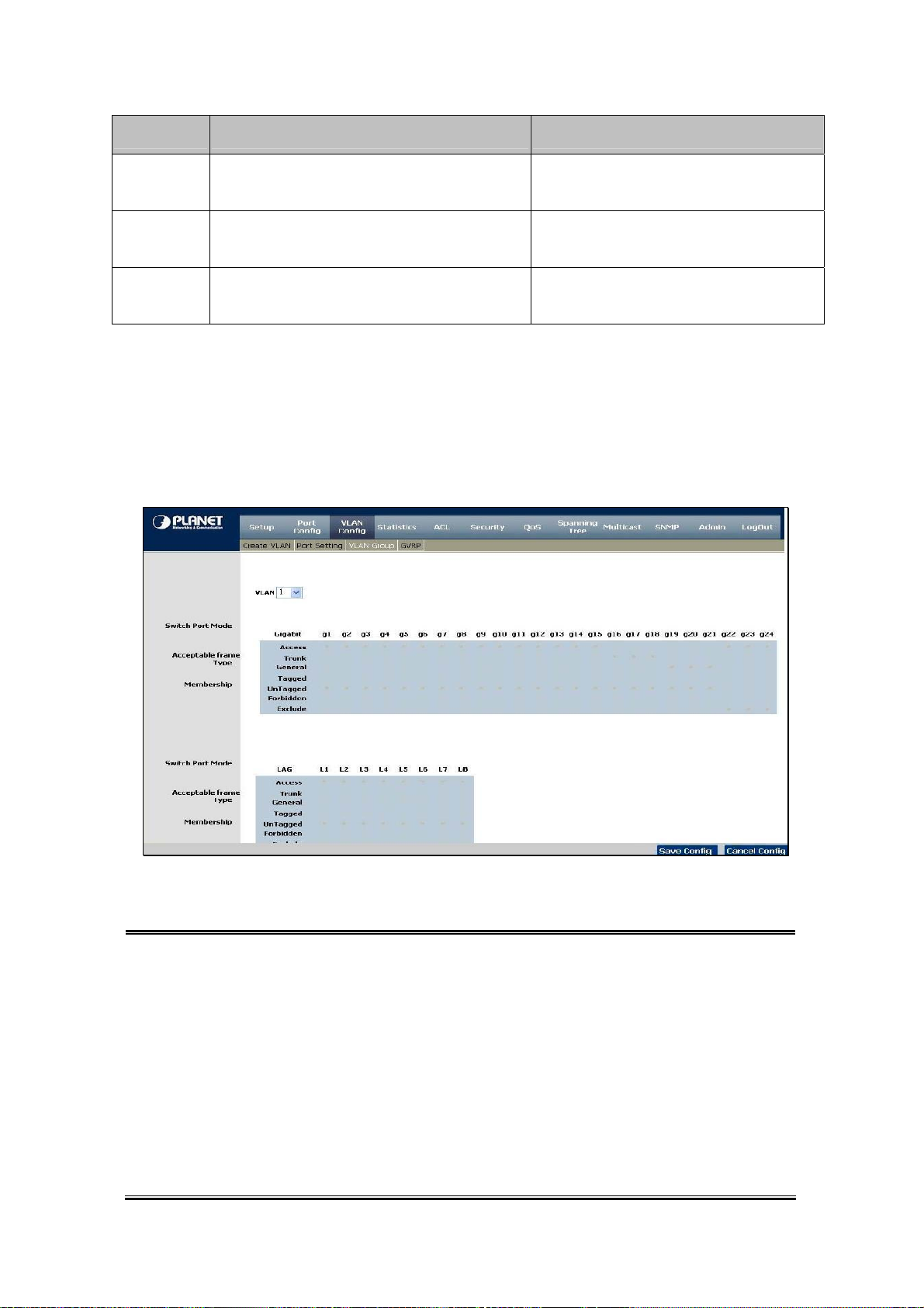
User’s Manual of WGSW-24020/WGSW-48040
Port Mode VLAN Membership Frame Leave
Access Belongs to a single untagged VLAN
Allowed to belongs to multiple untagged VLANs at
General
the same time
Allowed to belongs to multiple Tagged VLANs at
Trunk
the same time
( Tag=PVID be removed)
(Tag=PVID or Original VID be remained)
Untagged
Untagged
(Tag=PVID be removed)
Tagged
4.4.3 Ports to VLAN
The Ports to VLAN screen contains fields for configuring ports to a VLAN. The port default VLAN ID (PVID) is configured on the
Create VLAN screen. All untagged packets arriving to the device are tagged by the ports PVID. The Ports to VLAN screen
contains a Port Table for VLAN parameters for each port. Ports are assigned VLAN membership by selecting and configuring
the presented configuration options, please refer to figure 4-16.
e
The page contains the following fields:
VLAN Where means the VLAN number.
Access Indicates the port belongs to a single untagged VLAN. When a port is in Access
mode, the packet types which are accepted on the port cannot be designated.
Ingress filtering cannot be enabled/disabled on an access port.
Trunk Which indicates the port belongs to VLANs in which all ports are tagged, except for
one port that can be untagged.
General Which indicates the port belongs to VLANs, and each VLAN is user-defined as
tagged or untagged (full 802.1Q mode).
Tagged Defines the interface as a tagged member of a VLAN. All packets forwarded by the
interface are tagged. The packets contain VLAN information.
Untagged Packets forwarded by the interface are untagged.
Forbidden Forbidden ports are not included in the VLAN.
Exclude Excludes the interface from the VLAN. However, the interface can be added to the
VLAN through GVRP.
Figure 4-16 Ports to VLAN screen
-44-
Page 45

User’s Manual of WGSW-24020/WGSW-48040
4.4.4 GVRP
GARP VLAN Registration Protocol (GVRP) is specifically provided for automatic distribution of VLAN membership information
among VLAN-aware bridges. GVRP allows VLAN-aware bridges to automatically learn VLANs to bridge ports mapping, without
having to individually configure each bridge and register VLAN membership. The Global System LAG information displays the
same field information as the ports, but represents the LAG GVRP information. The GVRP screen (refer to 4-17) is divided into
two areas, GVRP and GVRP Table. The field definitions for both areas are the same.
Figure 4-17 GVRP configuration screen
The page contains the following fields:
Enable GVRP Enables and disables GVRP on the device.
Interface
GVRP State When the checkbox is checked, GVRP is enabled on the interface.
Dynamic VLAN Creation When the checkbox is checked, Dynamic VLAN creation is enabled on the interface.
GVRP Registration
Update
Displays the interface on which GVRP is enabled. Possible field values are:
Port - indicates the port number on which GVRP is enabled.
LAG - indicates the LAG number on which GVRP is enabled.
When the checkbox is checked, VLAN registration through GVRP is enabled on the
device.
The Update button adds the configured GVRP setting to the table at the bottom of the
screen.
-45-
Page 46

User’s Manual of WGSW-24020/WGSW-48040
4.5 Statistics
The Statistic of the switch, this field includes these parts as below:
4.5.1 RMON Statistics
The RMON Statistics screen (refer to figure 4-18) contains fields for viewing information about device utilization and errors that
occurred on the device.
Figure 4-18 RMON Statistics screen
The page contains the following fields:
Interface Indicates the device for which statistics are displayed. The possible field values are:
• Port - defines the specific port for which RMON statistics are displayed.
• LAG - defines the specific LAG for which RMON statistics are displayed.
Refresh Rate Defines the amount of time that passes before the interface statistics are refreshed. The
possible field values are:
• No Refresh, indicates that the RMON statistics are not refreshed.
• 15 Sec, which indicates that the RMON statistics are refreshed every 15 seconds.
• 30 Sec, which indicates that the RMON statistics are refreshed every 30 seconds.
• 60 Sec, which indicates that the RMON statistics are refreshed every 60 seconds.
Drop Events which displays the number of dropped events that have occurred on the interface since
the device was last refreshed.
Received Bytes (Octets) Displays the number of octets received on the interface since the device was last
refreshed. This number includes bad packets and FCS octets, but excludes framing bits.
Received Packets Displays the number of packets received on the interface, including bad packets,
Multicast and broadcast packets, since the device was last refreshed.
Broadcast Packets
Received
Multicast Packets
Received
CRC & Align Errors which displays the number of CRC and Align errors that have occurred on the interface
Undersize Packets Displays the number of undersized packets (less than 64 octets) received on the
Oversize Packets Displays the number of oversized packets (over 1518 octets) received on the interface
Which displays the number of good broadcast packets received on the interface since
the device was last refreshed. This number does not include Multicast packets.
Displays the number of good Multicast packets received on the interface since the
device was last refreshed.
since the device was last refreshed.
interface since the device was last refreshed.
since the device was last refreshed.
-46-
Page 47
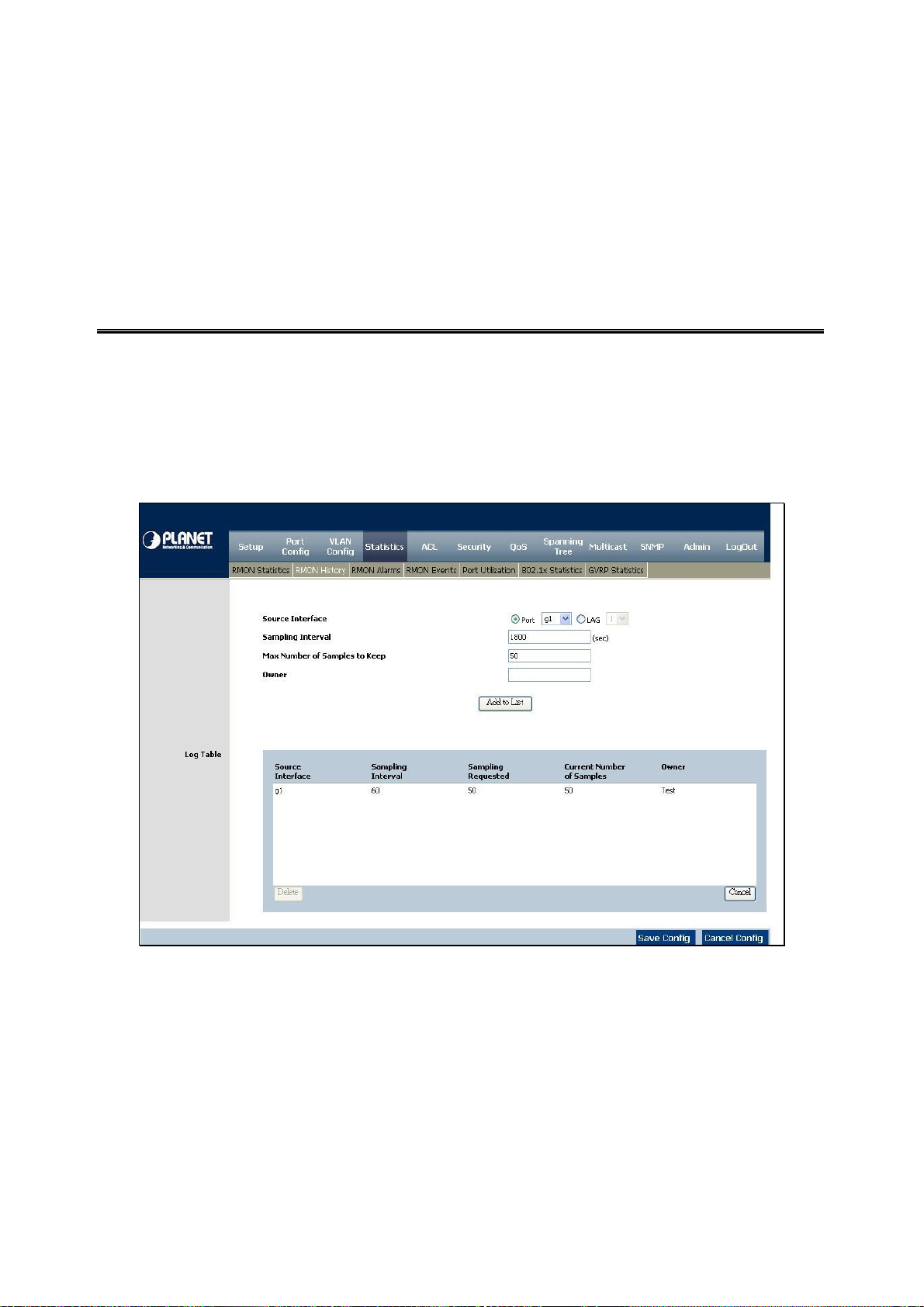
User’s Manual of WGSW-24020/WGSW-48040
Fragments Indicates the number of fragments (packets with less than 64 octets, excluding framing
bits, but including FCS octets) received on the interface since the device was last
refreshed.
Jabbers Indicates the total number of received packets that were longer than 1518 octets. This
number excludes frame bits, but includes FCS octets that had either a bad Frame
Check Sequence (FCS) with an integral number of octets (FCS Error) or a bad FCS with
a non-integral octet (Alignment Error) number. The field range to detect jabbers is
between 20 ms and 150 ms.
Collisions Displays the number of collisions received on the interface since the device was last
refreshed.
Frames of xx Bytes Number of xx-byte frames received on the interface since the device was last refreshed.
Clear Counters button, this option will reset all of the statistic counts.
Refresh Now button, which use this option to refresh the statistics.
4.5.2 RMON History
The RMON History contains information about samples of data taken from ports. For example, the samples may include
interface definitions or polling periods. The RMON History Control screen is divided into RMON History and Log Table.
Log Table includes the following parts (see figure 4-19).
The page contains the following fields:
Figure 4-19 RMON History screen
-47-
Page 48

User’s Manual of WGSW-24020/WGSW-48040
RMON History
• Source Interface Displays the interface from which the history samples were taken. The possible
field values are:
Port, specifies the port from which the RMON information was taken.
LAG, specifies the port from which the RMON information was taken.
• Sampling Interval Indicates (in seconds) the time that samplings are taken from the ports. The field
range is 1-3600. The default is 1800 seconds (equal to 30 minutes)
• Sampling
Requested
• Current Number of
Samples
• Owner Where displays the RMON station or user that requested the RMON information.
Use the Add to List button when you add the configured RMON sampling to the Log Table at the bottom of the screen
RMON History Table
The RMON History screen (see figure 4-20) contains interface specific statistical network samplings. Each table entry
Displays the number of samples to be saved. The field range is 1-65535.
The default value is 50.
Displays the current number of samples taken. View History button. This button
opens the RMON History screen.
The field range is 0-20 characters.
represents all counter values compiled during a single sample.
Figure 4-20 RMON History Table screen
The page contains the following fields:
-48-
Page 49

User’s Manual of WGSW-24020/WGSW-48040
Sample No Indicates the sample number from which the statistics were taken.
Received Bytes (Octets) Displays the number of octets received on the interface since the device was last
refreshed. This number includes bad packets and FCS octets, but excludes framing bits.
Received Packets Displays the number of packets received on the interface since the device was last
refreshed, including bad packets, Multicast and Broadcast packets.
Broadcast Packets Displays the number of good Broadcast packets received on the interface since the
device was last refreshed. This number does not include Multicast packets.
Multicast Packets Displays the number of good Multicast packets received on the interface since the
device was last refreshed.
CRC Align Errors Which displays the number of CRC and Align errors that have occurred on the interface
since the device was last refreshed.
Undersize Packets Displays the number of undersized packets (less than 64 octets) received on the
interface since the device was last refreshed.
Oversize Packets Displays the number of oversized packets (over 1518 octets) received on the interface
since the device was last refreshed.
Fragments Displays the number of fragments (packets with less than 64 octets, excluding framing
bits, but including FCS octets) received on the interface since the device was last
refreshed.
Jabbers Displays the total number of received packets that were longer than 1518 octets. This
number excludes frame bits, but includes FCS octets that had either a bad Frame
Check Sequence (FCS) with an integral number of octets (FCS Error) or a bad FCS with
a non-integral octet (Alignment Error) number. The field range to detect jabbers is
between 20 ms and 150 ms.
4.5.3 RMON Alarm
The RMON Alarm screen (see figure 4-21) contains fields for setting network alarms. Network alarms occur when a network
problem, or event, is detected. Rising and falling thresholds generate events.
Figure 4-21 RMON Alarm screen
-49-
Page 50

The page contains the following fields:
Alarm Entry Indicates a specific alarm.
Source Interface Displays the interface for which RMON statistics are displayed. The possible field
values are:
• Port, displays the selected port of the RMON statistics.
• LAG, displays the RMON statistics for the selected LAG.
Counter Name Displays the selected MIB variable.
Sample Type Defines the sampling method for the selected variable and comparing the value
against the thresholds. The possible field values are:
• Absolute, compares the values directly with the thresholds at the end of the
sampling interval.
• Delta, subtracts the last sampled value from the current value. The difference in
the values is compared to the threshold.
Rising Threshold Displays the rising counter value that triggers the rising threshold alarm. The rising
threshold is presented on top of the graph bars. Each monitored variable is
designated a color.
Rising Event Displays the mechanism in which the alarms are reported. The possible field values
are:
• LOG. Indicates there is not a saving mechanism for either the device or in the
• TRAP, indicates that an SNMP trap is generated, and sent via the Trap
• Both, indicates that both the Log and Trap mechanism are used to report
Falling Threshold Displays the falling counter value that triggers the falling threshold alarm. The
falling threshold is graphically presented on top of the graph bars. Each monitored
variable is designated a color.
Falling Event Displays the mechanism in which the alarms are reported. The possible field values
are:
• LOG, indicates there is not a saving mechanism for either the device or in the
• TRAP, indicates that a SNMP trap is generated, and sent via the Trap
• Both, indicates that both the Log and Trap mechanism are used to report
Startup A larm Displays the trigger that activates the alarm generation. Rising is defined by
crossing the threshold from a low-value threshold to a higher-value threshold.
Interval Defines the alarm interval time in seconds.
Owner Dhere displays the device or user that defined the alarm.
User’s Manual of WGSW-24020/WGSW-48040
management system. If the device is not reset, the entry remains in the Log
Table.
mechanism. The Trap can also be saved using the Trap mechanism.
alarms.
management system. If the device is not reset, the entry remains in the Log
Table.
mechanism. The Trap can also be saved using the Trap mechanism.
alarms.
Use the Add to List button when you add the RMON Alarms Table entry.
-50-
Page 51

User’s Manual of WGSW-24020/WGSW-48040
4.5.4 RMON Events
The RMON Events screen (see figure 4-22) contains fields for defining RMON events.
The page contains the following fields:
Add Event:
Event Entry Displays the event.
Community where displays the community to which the event belongs.
Description Displays the user-defined event description.
Type Describes the event type. Possible values are:
• None, where indicates that no event occurred.
• Log, indicates that the event is a log entry.
• Trap, indicates that the event is a trap.
• Log and Trap, indicates that the event is both a log entry and a trap.
Owner Where displays the device or user that defined the event. Use the Add to List button
when you add the configured RMON event to the Event Table at the bottom of the
screen (see figure 4-21).
The Event Table area contains the following additional field:
Figure 4-22 RMON Event screen
Time
Where displays the time that the event occurred
-51-
Page 52

User’s Manual of WGSW-24020/WGSW-48040
Press the RMON Event Log button to display the log store in the flash. Only the Event type is Log or Log and Trap, then the
entries appear. The screen in Figure 4-23 appears.
Figure 4-23 RMON Event Log Screen
4.5.5 Port Utilization
The Port Utilization screen (see figure 4-24) indicates the amount of resources each interface is currently consuming. Ports in
green are functioning normally, while ports in red are currently transmitting an excessive amount of network traffic.
Figure 4-24 Port Utilization screen
-52-
Page 53

The page includes the following fields:
User’s Manual of WGSW-24020/WGSW-48040
Refresh Rate
Indicates the amount of time that passes before the port utilization statistics are
refreshed. The possible field values are:
• No Refresh - indicates that the statistics are not refreshed.
• 15 Sec - indicates that the statistics are refreshed every 15 seconds.
• 30 Sec - indicates that the statistics are refreshed every 30 seconds.
• 60 Sec - indicates that the statistics are refreshed every 60 seconds.
4.5.6 802.1x Statistics
The 802.1X Statistics screen (see figure 4-25) contains information about EAP packets received on a specific port.
Figure 4-25 802.1x Statistics screen
-53-
Page 54

The page includes the following fields:
User’s Manual of WGSW-24020/WGSW-48040
Port
Refresh Rate
Name
Description
Packet
Indicates the port, which is polled for statistics.
Indicates the amount of time that passes before the EAP statistics are refreshed.
The possible field values are:
Displays the measured 802.1x statistic.
Describes the measured 802.1x statistic.
Displays the amount of packets measured for the particular 802.1x statistic.
4.5.7 GVRP Statistics
• No Refresh, indicates that the EAP statistics are not refreshed.
• 15 Sec, which indicates that the EAP statistics are refreshed every 15
seconds.
• 30 Sec, which indicates that the EAP statistics are refreshed every 30
seconds.
• 60 Sec, which indicates that the EAP statistics are refreshed every 60 seconds
The GVRP Statistics screen (see figure 4-26) contains device statistics for GVRP.
The GVRP Statistics screen is divided into two areas, GVRP Statistics Table and GVRP Error Statistics Table.
Figure 4-26 GVRP Statistics screen
-54-
Page 55

The following fields are relevant for both tables:
User’s Manual of WGSW-24020/WGSW-48040
Interface
Refresh Rate
The GVRP Statistics Table contains the following fields:
Join Empty
Specifies the interface type for which the statistics are displayed.
• Port, indicates port statistics are displayed.
• LAG, indicates LAG statistics are displayed.
Indicates the amount of time that passes before the GVRP statistics are refreshed.
The possible field values are:
• No Refresh, indicates that the GVRP statistics are not refreshed.
• 15 Sec, which indicates that the GVRP statistics are refreshed every 15
seconds.
• 30 Sec, which indicates that the GVRP statistics are refreshed every 30
seconds.
• 60 Sec, which indicates that the GVRP statistics are refreshed every 60
seconds.
Which displays the device GVRP Join Empty statistics.
Empty
Leave Empty
Join In
Leave In
Leave All
The GVRP Error Statistics Table contains the following fields:
Invalid Protocol ID
Invalid Attribute T ype
Attribute Value
Invalid Events
Displays the device GVRP Empty statistics.
By which displays the device GVRP Leave Empty statistics.
By which displays the device GVRP Join In statistics.
By which displays the device GVRP Leave in statistics.
By which displays the device GVRP Leave all statistics.
Where displays the device GVRP Invalid Protocol ID statistics.
Where displays the device GVRP Invalid Attribute ID statistics. Invalid.
Displays the device GVRP Invalid Attribute Value statistics. Invalid Attribute Length,
where displays the device GVRP Invalid Attribute Length statistics.
Where displays the device GVRP Invalid Events statistics. The Clear All Counters
button resets all tables.
-55-
Page 56

User’s Manual of WGSW-24020/WGSW-48040
-56-
Page 57

User’s Manual of WGSW-24020/WGSW-48040
4.6 ACL
An ACL consists of a set of rules which are matched sequentially against a packet. When a packet meets the match criteria of a
rule, the specified rule action (Permit/Deny) is taken and the additional rules are not checked for a match. On this menu the
interfaces to which an ACL applies must be specified, as well as whether it applies to inbound or outbound traffic. Rules for the
ACL are specified/created using the ACL Rule Configuration menu.
4.6.1 IP Based ACL
The IP Based ACL (Access Control List) screen (see figure 4-27) contains information for defining IP Based ACLs.
Figure 4-27 IP-Base ACL screen
-57-
Page 58

The Page contains the following fields:
User’s Manual of WGSW-24020/WGSW-48040
ACL Name
New ACL Name
Delete ACL
Action
Protocol
Select from List
Displays the user-defined IP based ACLs.
Defines a new user-defined IP based ACL.
By which deletes the selected ACL.
Indicates the action assigned to the packet matching the ACL. Packets are
forwarded or dropped. In addition, the port can be shutdown, a trap can be sent to
the network administrator, or a packet assigned rate limiting restrictions for
forwarding. The options are as follows:
• Permit, by which forwards packets which meet the ACL criteria.
• Deny, which drops packets which meet the ACL criteria.
• Shutdown, where drops packet that meets the ACL criteria, and disables the
port to which the packet was addressed. Ports are reactivated from the Port
Management screen.
By which creates an ACE (Access Control Event) based on a specific protocol
Where selects from a protocols list on which ACE can be based. The possible field
values are:
TCP Flags
• Any, matches the protocol to any protocol.
• EIGRP, which indicates that the Enhanced Interior Gateway Routing Protocol
(EIGRP) is used to classify network flows.
• ICMP, which indicates that the Internet Control Message Protocol (ICMP) is
used to classify network flows.
• IGMP, which indicates that the Internet Group Management Protocol (IGMP) is
used to classify network flows.
• TCP, which indicates that the Transmission Control Protocol is used to classify
network flows.
• OSPF, by which matches the packet to the Open Shortest Path First (OSPF)
protocol.
• UDP, which indicates that the User Datagram Protocol is used to classify
network flows.
• Protocol ID to Match, adds user-defined protocols to which packets are
matched to the ACE. Each protocol has a specific protocol number which is
unique. The possible field range is 0-255.
This filters packets by TCP flag. Filtered packets are either forwarded or dropped.
Filtering packets by TCP flags increases packet control, and network security. The
values that can be assigned are:
• Set, which enables filtering packets by selected flags.
• Unset, disables filtering packets by selected flags.
• Don’t care, which indicates that selected packets do not influence the packet
-58-
Page 59

User’s Manual of WGSW-24020/WGSW-48040
filtering process.
The TCP Flags that can be selected are:
• Urg, indicates the packet is urgent.
• Ack, indicates the packet is acknowledged.
• Psh, indicates the packet is pushed.
• Rst, indicates the connection is dropped.
• Syn, indicates request to start a session.
• Fin, indicates request to close a session.
Source Port
Destination Port
Source IP Address
Wildcard Mask
Destination IP
Address
Defines the TCP/UDP source port to which the ACE is matched. This field is active
only if 800/6-TCP or 800/17-UDP is selected in the Select from List drop-down
menu. The possible field range is 0 – 65535.
Defines the TCP/UDP destination port. This field is active only if 800/6-TCP or
800/17-UDP is selected in the Select from List drop-down menu. The possible field
range is 0 – 65535.
Matches the source port IP address to which packets are addressed to the ACE.
Defines the source IP address wildcard mask. Wildcard masks specify which bits
are used and which bits are ignored.
A wild card mask of 255.255.255.255 indicates that no bit is important.
A wildcard of 0.0.0.0 indicates that all the bits are important.
For example, if the source IP address 149.36.184.198 and the wildcard mask is
255.36.184.00, the first eight bits of the IP address are ignored, while the last eight
bits are used.
Matches the destination port IP address to which packets are addressed to the ACE
Wildcard Mask
Match DSCP
Match IP Precedence
Use the Add to List button when you add the configured IP Based ACLs to the IP Based ACL Table at the bottom of
the screen.
Defines the destination IP address wildcard mask.
Matches the packet DSCP value to the ACE. Either the DSCP value or the IP
Precedence value is used to match packets to ACLs.
The possible field range is 0-63.
Matches the packet IP Precedence value to the ACE. Either the DSCP value or the
IP Precedence value is used to match packets to ACLs.
The possible field range is 0-7.
-59-
Page 60

User’s Manual of WGSW-24020/WGSW-48040
4.6.2 IP Based ACL Configure Sample
This section shows how to build a IP Based ACL and apply to specify interface.
■ Sample Case: Deny IP packets to specific Class C network
¾ Purpose:
Verify a positive and negative matches to network IP address with a Class C (24 bit mask) , no matter the rule defined as
permit or deny.
1. Any packets pass through the switch will be dropped – if the Destination IP Addresses match specific Class C.
2. Any packets pass through the switch will be forwarded – if the Destination IP Addresses not match specific Class C.
¾ Case Design:
Action DENY
Match IP
Source IP Address Any
Destination IP Address
Applied Interface Interface g1
¾ Device Connection and Configuration:
Class C
172.16.0.0 / 255.255.255.0
-60-
Page 61

User’s Manual of WGSW-24020/WGSW-48040
Target
Any
The procedure as following
ID Source Address Destination Address
3 Any
Stream
Protocol
172.16.0.0 /
255.255.255.0
■ Create Deny ACL and add to list.
1. [DENY Rule]: Choose “New ACL Name”, then key in “Deny-IP Destination A”. Choose “Action”—“Deny”.
(The ACL Name can de entered with other policy name).
2. [DENY Rule]: Keep the “Source IP Address” and “W ild Card Mask” be blanked.
3. [DENY Rule]: Enter “172.16.0.0” in the “Destination IP Address” and “0.0.0.255” in the Wild Card Mask.
4. After click “Add to List" button, the entry would be show at the table.
Any
-61-
Page 62
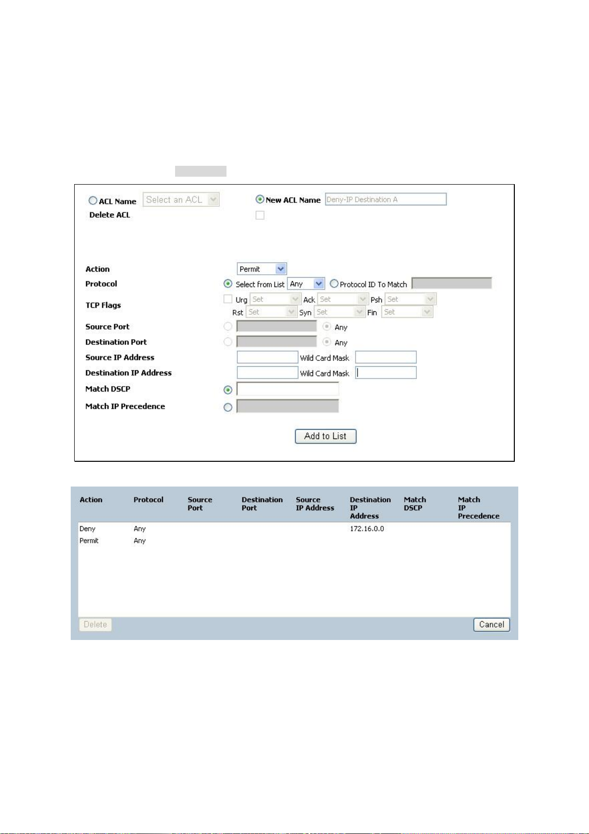
User’s Manual of WGSW-24020/WGSW-48040
■ Create Permit ACL and add to list
5. [Permit Rule]: Within the same ACL “Deny-IP Destination A”, choose “Action”—“Permit”.
6. [Permit Rule]: Keep the “Source IP Address” and “Wild Card Mask” be blanked.
7. [Permit Rule]: Keep the “Destination IP Address” and “Wild Card Mask” be blanked.
8. After click “Add to List" button, the entry would be show at the table.
9. Rember to click the "Save Config" button.
■ Binding the IP ACL to specify interface
10. Select “Security” \”ACL Binding” in the Menu bar.
11. Choose Port “g1” at the Interface.
12. Choose “IP Based ACL”, select ACL name with “Deny-Source A” – that we had been created at step-1. Click
“Add to List" button, the entry would be show at the table.
-62-
Page 63
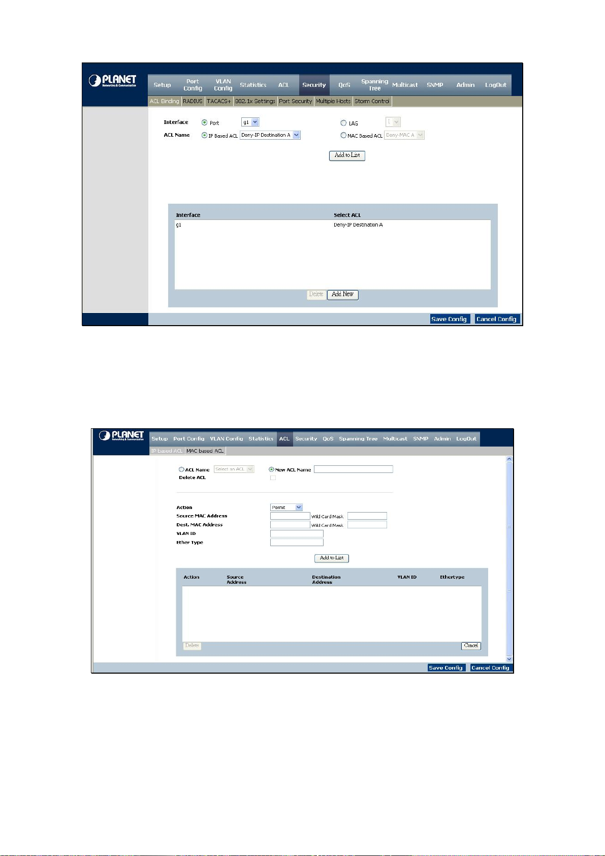
User’s Manual of WGSW-24020/WGSW-48040
4.6.3 MAC Based ACL
The MAC Based ACL screen (see figure 4-28) allows a MAC based ACL to be defined. ACEs can be added only if the ACL is not
bound to an interface.
Figure 4-28 MAC-Base ACL screen
-63-
Page 64

The Page contains the following fields:
User’s Manual of WGSW-24020/WGSW-48040
ACL Name
New ACL Name
Delete ACL
Action
Source MAC Address
Wildcard Mask
Displays the user-defined MAC based ACLs
Specifies a new user-defined MAC based ACL name.
By which deletes the selected ACL
Indicates the ACL forwarding action. Possible field values are:
• Permit, by which forwards packets which meet the ACL criteria.
• Deny, drops packets which meet the ACL criteria.
• Shutdown, where drops packet that meet the ACL criteria, and disables the
port to which the packet was addressed.
Matches the source MAC address to which packets are addressed to the ACE.
Defines the source IP address wildcard mask. Wildcard masks specify which bits
are used and ignored.
A wild card mask of 255.255.255.255 indicates that no bit is important.
A wildcard of 0.0.0.0 indicates that all the bits are important.
For example, if the source IP address 149.36.184.198 and the wildcard mask is
255.36.184.00, the first eight bits of the IP address are ignored, while the last eight
bits are used.
Dest. MAC Address
VLAN ID
Ether Type
Use the “Add to List” button to add the configured MAC Based ACLs to the MAC Based ACL Table at the bottom of
the screen.
Where matches the destination MAC address to which packets are addressed to
the ACE.
Wildcard Mask, which defines the destination IP address wildcard mask.
Which matches the packet’s VLAN ID to the ACE.
The possible field values are 2 to 4094.
Where specifies the packet’s Ethernet type.
-64-
Page 65

User’s Manual of WGSW-24020/WGSW-48040
4.6.4 MAC Based ACL Configure Sample
This chapter will teah you how to configure a MAC based ACL in the Switch.
■ Sample Case: Deny IP packets to specific Class C network
¾ Purpose:
When the workstation with IP address 192.168.99.188 and MAC address 00-11-08-57-E0-1E ping to PC with IP address
192.168.99.57 and MAC address 00-30-4F-1D-9F-DE, use MAC based ACL function from ACL to deny or shutdown and
permit the traffic transmit ability of notebook that connect to port 8 of Switch.
¾ Case Design:
Action DENY
Match MAC Address
Source MAC Address 00-11-08-57-E0-1E
Destination MAC Address 00-30-4F-1D-9F-DE
Applied Interface Interface g2
¾ Device Connection and Configuration:
Setting procedure from Switch Web interface:
■ Create Deny MAC ACL and add to list
1. Please enter into Web interface and choose "ACL" function,
2. Then choose "MAC based ACL" function.
3. Please input a new ACL name, for example: “Deny MAC A”.
-65-
Page 66
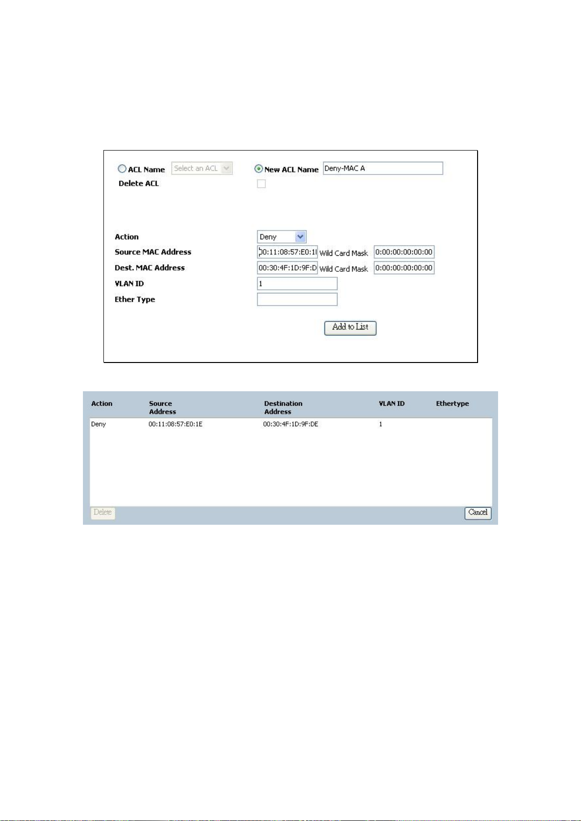
User’s Manual of WGSW-24020/WGSW-48040
4. To defined "Permit", "Deny" or "Shutdown" from Action item.
5. [Deny Rule]: Input Source MAC Address "00:11:08:57:E0:1E" with Wild Card Mask "00:00:00:00:00:00".
6. [Deny Rule]: Enter Dest. Mac Address "00:30:4F:1D:9F:DE" with Wild Card Mask “00:00:00:00:00:00".
7. [Deny Rule]:Input the VLAN ID and default VLAN ID is 1.
8. Press "Add to List" button to complete this setting.
■ Create Permit MAC ACL and add to list (
9. [Permit Rule]: Within the same ACL “Deny-MAC A”, choose “Action”—“Permit”.
10. [Permit Rule]: Keep the “Source MAC Address” and “Wild Card Mask” be blanked.
11. [Permit Rule]: Keep the “Destination MAC Address” and “Wild Card Mask” be blanked.
12. After click “Add to List" button, the entry would be show at the table.
To allow all other packets be forwarded)
-66-
Page 67

User’s Manual of WGSW-24020/WGSW-48040
13. Please press "Save Config" to save current setting.
■ Binding the MAC ACL to specify interface
14. Select “Security” \”ACL Binding” in the Menu bar.
15. Choose Port “g2” from Interface item.
16. Choose “MAC Based ACL”, select ACL name with “Deny-MAC A” – that we had been created at step-1. Click “Add
to List" button, the entry would be show at the table.
-67-
Page 68
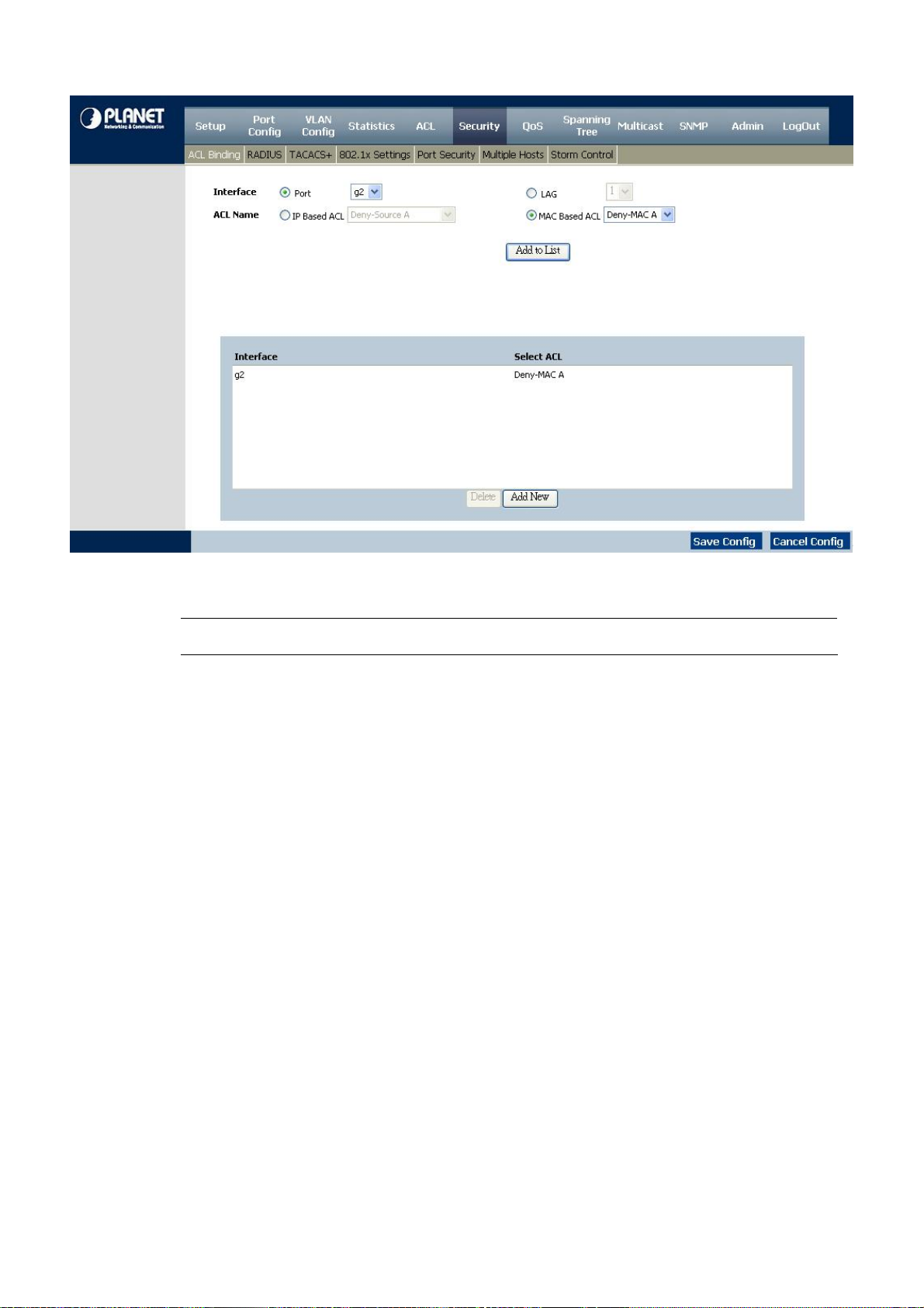
User’s Manual of WGSW-24020/WGSW-48040
17. Please press "Save Config" to save current setting.
#Notice: If action "shutdown" is selected, the port will be force disabled
-68-
Page 69
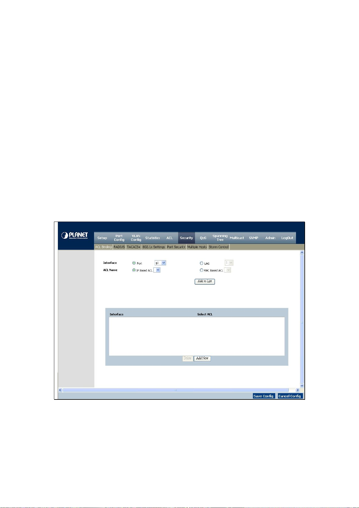
User’s Manual of WGSW-24020/WGSW-48040
4.7 Security
This section is to control the security access of the Switch, includes the user access and management control.
The Security function contains links to the following topics:
• ACL Binding
• RADIUS
• TACACS+
• 802.1x Settings
• Port Security
• Multiple Hosts
• Storm Control
4.7.1 ACL Binding
When an ACL is bound to an interface, all the ACE (Access Control Event) rules that have been defined are applied to the
selected interface. Whenever an ACL is assigned on a port, LAG or, VLAN, flows from that ingress interface that do not match
the ACL are matched to the default rule, which is Drop unmatched packets. You can refer to figure 4-29.
Figure 4-29 ACL Binding screen
-69-
Page 70
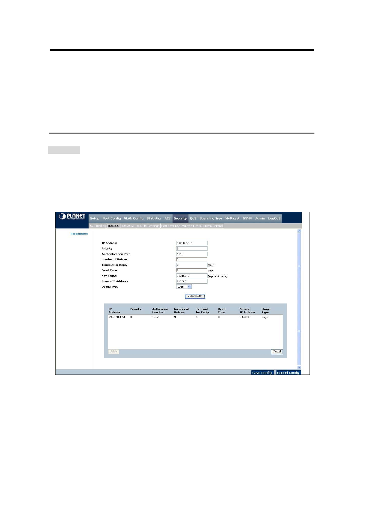
The Page contains the following fields:
User’s Manual of WGSW-24020/WGSW-48040
Interface
ACL Name
Use the Add to List button to add the ACL Binding configuration to the ACL Binding Table at the bottom of the screen.
Indicates the interface to which the ACL is bound. The selection includes:
• Port, indicates port to apply the ACL
• LAG, indicates LAG to apply the ACL
Indicates the ACL which is bound to the interface. The selection includes:
• IP Based ACL
• MAC Based ACL
4.7.2 Radius
Remote Authorization Dial-In User Service (RADIUS) servers provide additional security for networks. RADIUS servers provide
a centralized authentication method for web access (see figure 4-30).
Figure 4-30 RADIUS screen
-70-
Page 71

The Page contains the following fields:
User’s Manual of WGSW-24020/WGSW-48040
IP Address
Priority
Authentication Port
Number of Retries
Timeout for Reply
Dead Time
Key String
The Authentication Server IP address.
Displays the server priority. The possible values are 0-65535, where 1 is the
highest value. The RADIUS Server priority is used to configure the server query
order.
Identifies the authentication port. The authentication port is used to verify the
RADIUS server authentication. The authenticated port default is 1812.
Defines the number of transmitted requests sent to RADIUS server before a failure
occurs. The possible field values are 1 - 10. 3 is the default value.
This defines the amount of the time in seconds the device waits for an answer from
the RADIUS server before retrying the query, or switching to the next server.
The possible field values are 1 - 30. 3 is the default value.
This defines the amount of time (minutes) that a RADIUS server is bypassed for
service requests. The range is 0-2000. The Dead Time default is 0 minutes.
This defines the default key string used for authenticating and encrypting all
RADIUS communications between the device and the RADIUS server.
This key must match the RADIUS encryption.
Source IP Address
Usage Type
Use the Add to List button when you add the RADIUS configuration to the RADIUS Table at the bottom of the screen.
Defines the source IP address that is used for communication with RADIUS
servers.
Specifies the RADIUS server authentication type. The default value is Login. The
possible field values are:
• Login, indicates that the RADIUS server is used for authenticating user name
and passwords.
• 802.1X, indicates that the RADIUS server is used for 802.1X authentication.
• All, where indicates that the RADIUS server is used for authenticating user
name and passwords, and 802.1X port authentication.
-71-
Page 72

User’s Manual of WGSW-24020/WGSW-48040
4.7.3 TACACS+
The device provides Terminal Access Controller Access Control System (TACACS+) client support. TACACS+ provides
centralized security for validation of users accessing the device. TACACS+ provides a centralized user management system,
while still retaining consistency with RADIUS and other authentication processes. The TACACS+ protocol ensures network
integrity through encrypted protocol exchanges between the device and TACACS+ server. You can refer to figure 4-31.
The Page contains the following fields:
Host IP Address Indicates the TACACS+ Server IP address.
Priority Displays the order in which the TACACS+ servers are used. The default is 0.
Source IP Address By which displays the device source IP address used for the TACACS+ session
between the device and the TACACS+ server.
Key String This defines the authentication and encryption key for TACACS+ server. The key
must match the encryption key used on the TACACS+ server.
Authentication Port Displays the port number through which the TACACS+ session occurs.
The Timeout for Reply This displays the amount of time that passes before the connection between the
device and the TACACS+ server times out. The field range is 1-30 seconds.
Status Displays the connection status between the device and the TACACS+ server. The
possible field values are:
• Connected, there is currently a connection between the device and the
• Not Connected, there is not currently a connection between the device and
Single Connection Maintains a single open connection between the device and the TACACS+ server
when selected the Add to List button to add the TACACS+ configuration to the
TACACS+ table at the bottom of the screen.
Figure 4-31 TACACS+ screen
TACACS+ server.
the TACACS+ server.
-72-
Page 73
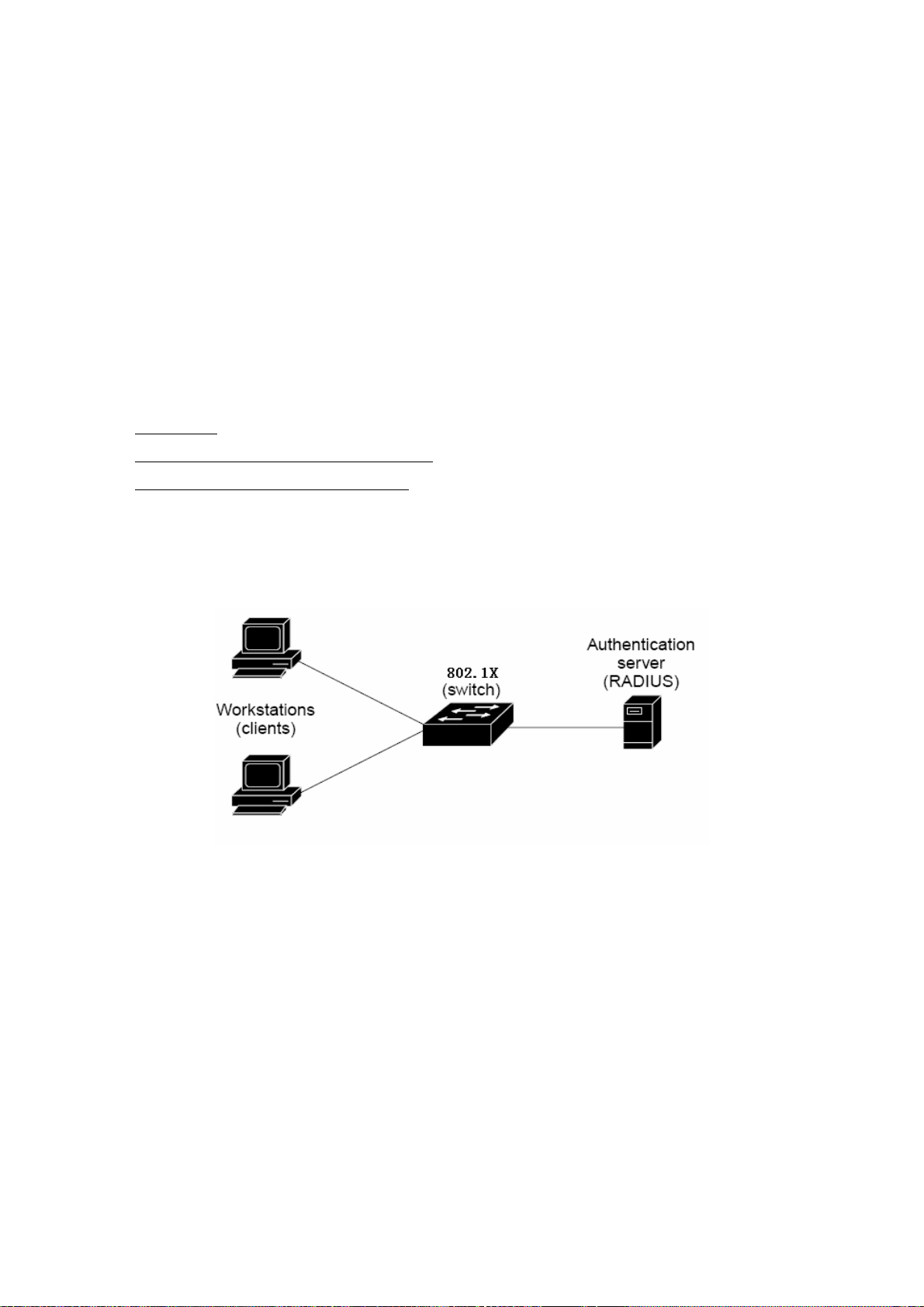
User’s Manual of WGSW-24020/WGSW-48040
4.7.4 802.1x settings
Understanding IEEE 802.1X Port-Based Authentication
The IEEE 802.1X standard defines a client-server-based access control and authentication protocol that restricts unauthorized
clients from connecting to a LAN through publicly accessible ports. The authentication server authenticates each client
connected to a switch port before making available any services offered by the switch or the LAN.
Until the client is authenticated, 802.1X access control allows only Extensible Authentication Protocol over LAN (EAPOL) traffic
through the port to which the client is connected. After authentication is successful, normal traffic can pass through the port.
This section includes this conceptual information:
•
Device Roles
• Authentication Initiation and Message Exchange
• Ports in Authorized and Unauthorized States
Device Roles
With 802.1X port-based authentication, the devices in the network have specific roles as shown below.
z Client—the device (workstation) that requests access to the LAN and switch services and responds to requests from the
switch. The workstation must be running 802.1X-compliant client software such as that offered in the Microsoft
Windows XP operating system. (The client is the supplicant in the IEEE 802.1X specification.)
z Authen tication server—performs the actual authentication of the client. The authentication server validates the identity
of the client and notifies the switch whether or not the client is authorized to access the LAN and switch services.
Because the switch acts as the proxy, the authentication service is transparent to the client. In this release, the Remote
Authentication Dial-In User Service (RADIUS) security system with Extensible Authentication Protocol (EAP)
extensions is the only supported authentication server; it is available in Cisco Secure Access Control Server version 3.0.
RADIUS operates in a client/server model in which secure authentication information is exchanged between the
RADIUS server and one or more RADIUS clients.
z Switch (802.1X device)—controls the physical access to the network based on the authentication status of the client. The
switch acts as an intermediary (proxy) between the client and the authentication server, requesting identity information
-73-
Page 74

User’s Manual of WGSW-24020/WGSW-48040
from the client, verifying that information with the authentication server, and relaying a response to the client. The switch
includes the RADIUS client, which is responsible for encapsulating and decapsulating the Extensible Authentication
Protocol (EAP) frames and interacting with the authentication server. When the switch receives EAPOL frames and
relays them to the authentication server, the Ethernet header is stripped and the remaining EAP frame is
re-encapsulated in the RADIUS format. The EAP frames are not modified or examined during encapsulation, and the
authentication server must support EAP within the native frame format. When the switch receives frames from the
authentication server, the server's frame header is removed, leaving the EAP frame, which is then encapsulated for
Ethernet and sent to the client.
Authentication Initiation and Message Exchange
The switch or the client can initiate authentication. If you enable authentication on a port by using the dot1x port-control auto
interface configuration command, the switch must initiate authentication when it determines that the port link state transitions
from down to up. It then sends an EAP-request/identity frame to the client to request its identity (typically, the switch sends an
initial identity/request frame followed by one or more requests for authentication information). Upon receipt of the frame, the
client responds with an EAP-response/identity frame.
However, if during bootup, the client does not receive an EAP-request/identity frame from the switch, the client can initiate
authentication by sending an EAPOL-start frame, which prompts the switch to request the client's identity.
If 802.1X is not enabled or supported on the network access device, any EAPOL frames from the
client are dropped. If the client does not receive an EAP-request/identity frame after three attempts
#Notice:
When the client supplies its identity, the switch begins its role as the intermediary, passing EAP frames between the client and
the authentication server until authentication succeeds or fails. If the authentication succeeds, the switch port becomes
authorized.
The specific exchange of EAP frames depends on the authentication method being used. Following figure shows a message
exchange initiated by the client using the One-Time-Password (OTP) authentication method with a RADIUS server.
to start authentication, the client transmits frames as if the port is in the authorized state. A port in
the authorized state effectively means that the client has been successfully authenticated.
-74-
Page 75

User’s Manual of WGSW-24020/WGSW-48040
Ports in Authorized and Unauthorized States
The switch port state determines whether or not the client is granted access to the network. The port starts in the unauthorized
state. While in this state, the port disallows all ingress and egress traffic except for 802.1X protocol packets. When a client is
successfully authenticated, the port transitions to the authorized state, allowing all traffic for the client to flow normally.
If a client that does not support 802.1X is connected to an unauthorized 802.1X port, the switch requests the client's identity. In
this situation, the client does not respond to the request, the port remains in the unauthorized state, and the client is not granted
access to the network.
In contrast, when an 802.1X-enabled client connects to a port that is not running the 802.1X protocol, the client initiates the
authentication process by sending the EAPOL-start frame. When no response is received, the client sends the request for a
fixed number of times. Because no response is received, the client begins sending frames as if the port is in the authorized
state.
If the client is successfully authenticated (receives an Accept frame from the authentication server), the port state changes to
authorized, and all frames from the authenticated client are allowed through the port. If the authentication fails, the port remains
in the unauthorized state, but authentication can be retried. If the authentication server cannot be reached, the switch can
retransmit the request. If no response is received from the server after the specified number of attempts, authentication fails,
and network access is not granted.
When a client logs off, it sends an EAPOL-logoff message, causing the switch port to transition to the unauthorized state.
If the link state of a port transitions from up to down, or if an EAPOL-logoff frame is received, the port returns to the unauthorized
state.
-75-
Page 76

User’s Manual of WGSW-24020/WGSW-48040
■ 802.1X Settings of WGSW-Switch
Port based authentication enables authenticating system users on a per-port basis via an external server. Only authenticated
and approved system users can transmit and receive data. Ports are authenticated via the RADIUS server using the
Extensible Authentication Protocol (EAP). Refer to figure 4-32.
The Page contains the following fields:
Enable 802.1x
Port
Status Port Control
Enable Periodic
Re-authentication
Place a checkmark in the check box to enable 802.1x, authentication.
Indicates the port name.
This specifies the port authorization state. The possible field values are as follows:
• Force-Authorized, the controlled port state is set to Force-Authorized (forward
• Force-Unauthorized, the controlled port state is set to Force-Unauthorized
Permits immediate port re-authentication. The Setting Timer button opens the
Setting Timer screen to configure ports for 802.1x functionality.
Figure 4-32 802.1x setting screen
traffic).
(discard traffic).
-76-
Page 77

User’s Manual of WGSW-24020/WGSW-48040
Setting Timer
On this screen, it includes port, re-authentication, resending EAP …. (Refer to figure 4-33)
The Page contains the following fields:
Quiet Period
Resending EAP
Max EAP Requests
Supplicant Timeout
Server Timeout
Specifies the number of seconds that the switch remains in the quiet state
following a failed authentication exchange.
(Range: 0-65535).
Specifies the number of seconds that the switch waits for a response to an EAP request/ identity frame, from the supplicant (client), before resending the
requests.
Which the total amount of EAP requests sent. If a response is not received after
the defined period, the authentication process is restarted.
The field default is 2 retries.
Which displays the number of seconds that lapses before EAP requests are
resent to the supplicant (Range: 1-65535).
The field default is 30 seconds.
Which specifies the number of seconds that lapses before the switch resends a
request to the authentication server (Range: 1-65535).
Figure 4-33 Setting Timer parameter screen
The field default is 30 seconds.
-77-
Page 78
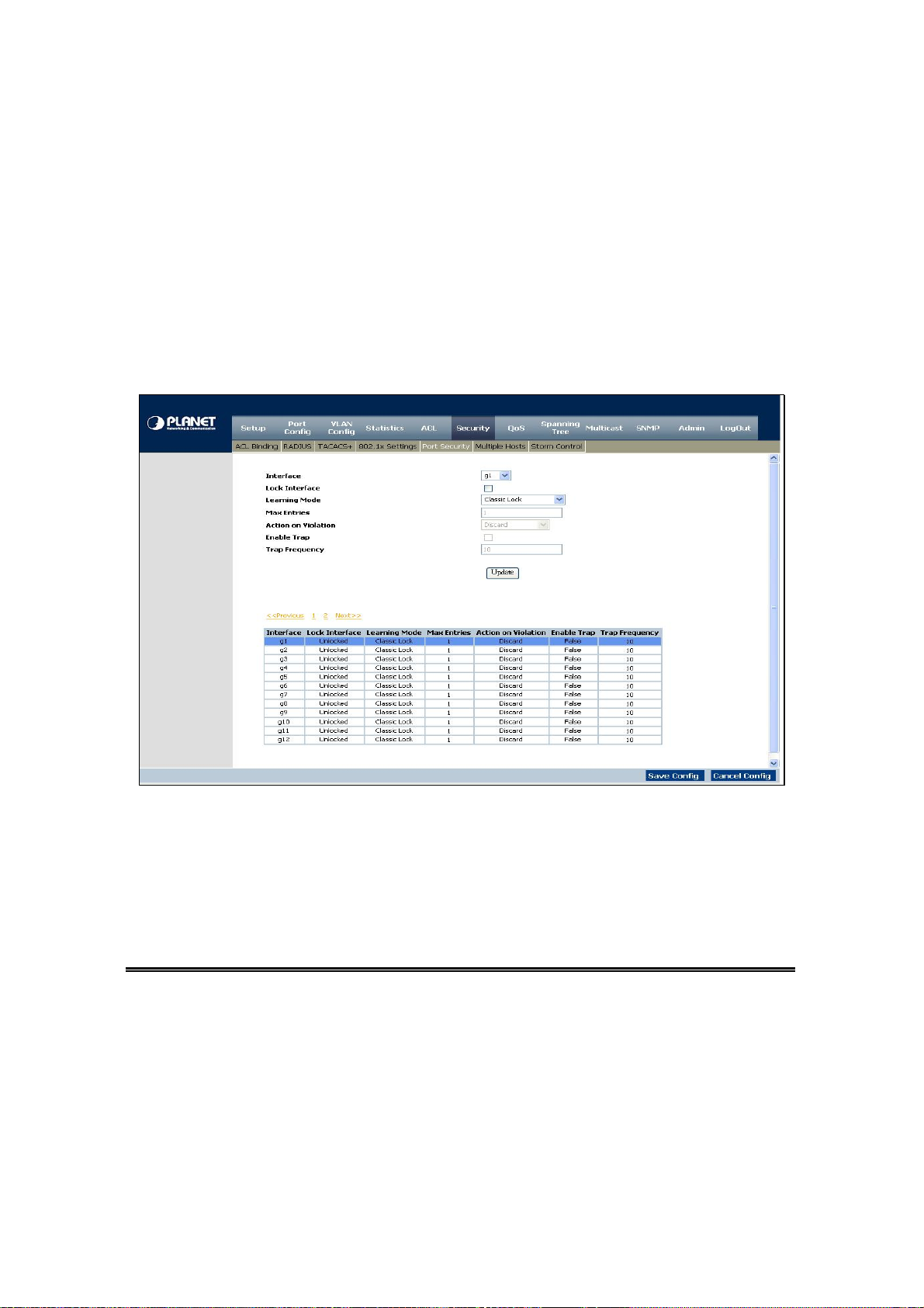
User’s Manual of WGSW-24020/WGSW-48040
4.7.5 Port Security
Work security screen (see figure 4-34) can be increased by limiting access on a specific port only to users with specific MAC
addresses. MAC addresses can be dynamically learned or statically configured. Locked port security monitors both received
and learned packets that are received on specific ports. Access to the locked port is limited to users with specific MAC
addresses. These addresses are either manually defined on the port, or learned on that port up to the point when it is locked.
When a packet is received on a locked port, and the packet source MAC address is not tied to that port (either it was learned on
a different port, or it is unknown to the system), the protection mechanism is invoked, and can provide various options.
Unauthorized packets arriving at a locked port are either: Forwarded, Discarded with no trap, Discarded with a trap, Cause the
port to be shut down.
Figure 4-34 Port Security screen
Locked port security also enables storing a list of MAC addresses in the configuration file. The MAC address list can be
restored after the device has been reset.
Disabled ports are activated from the Port Security page.
Interface
Lock Interface
Learning Mode
Where displays the port or LAG name
Which selecting this option locks the specified interface.
Where defines the locked port type. The Learning Mode field is enabled only if
Locked is selected in the Interface Status field. The possible field values are:
• Classic Lock, by which locks the port using the classic lock mechanism. The
port is immediately locked,
regardless of the number of addresses that have already been learned.
• Limited Dynamic Lock, which locks the port by deleting the current dynamic
-78-
Page 79

User’s Manual of WGSW-24020/WGSW-48040
MAC addresses associated with the port. The port learns up to the maximum
addresses allowed on the port. Both relearning and aging MAC addresses are
enabled.
Max Entries
Action on Violation
Enable Trap
Trap Frequency
Specifies the number of MAC addresses that can be learned on the port. The Max
Entries field is enabled only if Locked is selected in the Interface Status field. In
addition, the Limited Dynamic Lock mode is selected.
The default is 1.
Where indicates the action to be applied to packets arriving on a locked port. The
possible field values are:
• Discard, which discards packets from any unlearned source. This is the
default value.
• Forward Normal, forwards packets from an unknown source without learning
the MAC address.
• Discard Disable, which discards packets from any unlearned source and
shuts down the port. The port remains shut down until reactivated, or until the
device is reset.
This enables traps when a packet is received on a locked port.
Which the amount of time (in seconds) between traps.
The default value is 10 seconds
#Notice In order to change the Learning Mode, the Lock Interface must be set to unlocked. Once the mode is
changed, the Lock Interface can be reinstated.
-79-
Page 80

User’s Manual of WGSW-24020/WGSW-48040
4.7.6 Multiple Hosts
The Multiple Hosts screen (see figure 4-35) allows network managers to configure advanced port-based authentication settings
for specific ports and VLANs.
The Page contains the following fields:
Port
Enable Multiple Hosts
Action on Violation
Displays the port number for which advanced port-based
authentication is enabled.
When checked, indicates that multiple hosts are enabled. Multiple
hosts must be enabled in order to either disable the ingress-filter, or to
use port-lock security on the selected port.
This defines the action to be applied to packets arriving in single-host
mode, from a host whose MAC address is not the supplicant MAC
address. The possible field values are:
• Discard, which discards the packets. This is the default value.
• Forward, by which forwards the packet.
• DiscardDisable, discards the packets and shuts down the port.
Figure 4-35 Multiple Hosts screen
The ports remains shut down until reactivated, or until the device
is reset.
Enable Traps
When checked, indicates that traps are enabled for Multiple Hosts.
-80-
Page 81

User’s Manual of WGSW-24020/WGSW-48040
Trap Frequency
Status
Defines the time period by which traps are sent to the host. The Trap
Frequency (1-1000000) field can be defined only if multiple hosts are
disabled.
The default is 10 seconds.
Where indicates the host status.
4.7.7 Storm control
A BroadcastStorm is a result of an excessive amount of broadcast messages simultaneously transmitted across a network by a
single port. Forwarded message responses are heaped onto the network, straining network resources or causing the network to
time out.
The system measures the incoming Broadcast and Multicast frame rate separately on each port, and discard frames when the
rate exceeds a user-defined rate.
The Storm Control page provides fields for enabling and configuring Storm Control. The screen in Figure 4-36 appears.
The Page contains the following fields:
Port
Broadcast Control
Mode
Displays the port number for which storm control is enabled
This indicates whether broadcast packet types are forwarded on the specific
interface.
By which specifies the Broadcast mode currently enabled on the device. The
possible field values are:
• Unknown Unicast, Multicast & Broadcast, counts Unicast, Multicast, and
Figure 4-36 Storm Control screen
Broadcast traffic.
-81-
Page 82

User’s Manual of WGSW-24020/WGSW-48040
• Multicast & Broadcast, counts Broadcast and Multicast traffic together.
• Broadcast Only, counts only Broadcast traffic.
Rate Threshold
Where the maximum rate (packets per second) at which unknown packets are
forwarded. The range is 70 -100000.
The default value is 3500.
4.8 QoS
Network traffic is usually unpredictable, and the only basic assurance that can be offered is best effort traffic delivery. To
overcome this challenge, Quality of Service (QoS) is applied throughout the network. This ensures that network traffic is
prioritized according to specified criteria, and that specific traffic receives preferential treatment. And Cos Settings, Queue
settings, Dscp Settings, Bandwidth, Basic Mode, Advanced mode are provided.
4.8.1 CoS Settings
The terms Class of Service (CoS) and QoS are used in the following:
CoS provides varying Layer 2 traffic services. CoS refers to classification of traffic to traffic-classes, which are handled as an
aggregate whole, with no per-flow settings. CoS is usually related to the 802.1p service that classifies flows according to their
Layer 2 priority, as set in the VLAN header. QoS refers to Layer 2 traffic and above. QoS handles per-flow settings, even within a
single traffic class.
The CoS Settings screen (see figure 4-37) contains fields for enabling or disabling CoS. In addition, the Trust mode can be
selected. The Trust mode relies on predefined fields within the packet to determine the egress queue settings. (To configure the
Trust Mode, see 4.8.5.)
The CoS Settings screen has two areas, CoS Settings and CoS to Queue.
-82-
Page 83

User’s Manual of WGSW-24020/WGSW-48040
Figure 4-37 CoS Settings screen
The Page contains the following fields:
CoS Mode
Class of Service
Queue
The Restore Defaults button restores the device factory defaults for mapping CoS values to a forwarding queue.
This indicates if QoS is enabled on the interface. The possible values are:
• Disable, disables QoS on the interface.
• Basic, enables QoS on the interface.
• Advanced, enables the Advanced Mode QoS on the interface.
Specifies the CoS priority tag values, where zero is the lowest and 7 is the highest
Defines the traffic forwarding queue to which the CoS priority is mapped.
Four traffic priority queues are supported.
-83-
Page 84

CoS Default:
The Table contains the following fields:
User’s Manual of WGSW-24020/WGSW-48040
Interface
Default CoS
Restore Defaults
LAG
Interface to which the CoS configuration applies.
Determines the default CoS value for incoming packets for which a VLAN tag is not
defined. The possible field values are 0-7.
The default CoS is 0.
Restores the device factory defaults for mapping CoS values to forwarding queue.
LAG to which the CoS configuration applies.
4.8.2 Queue Setting
The Queue Setting screen (see figure 4-38) contains fields for defining the QoS queue forwarding types.
The page contains the following fields:
Strict Priority
WRR
Queue
WRR Weight
This indicates that traffic scheduling for the selected queue is based strictly on the
queue priority.
This indicates that traffic scheduling for the selected queue is based strictly on the
WRR.
Shows the queue for which the queue settings are displayed.
The possible field range is 1 - 4.
This displays the WRR weights to queues.
Default Rate 1:2:4:8
Figure 4-38 Queue Setting screen
-84-
Page 85

User’s Manual of WGSW-24020/WGSW-48040
% of WRR Bandwidth
Displays the amount of bandwidth assigned to the queue.
These values are fixed and are not user- defined.
• 6.67%
• 13.33%
• 26.67%
• 53.33%
4.8.3 DSCP Settings
The DSCP Settings screen (see figure 4-39) enables mapping DSCP values to specific queues.
Figure 4-39 DSCP Settings screen
The DSCP Settings screen contains the following fields:
DSCP
Queue
.,.
Indicates the Differentiated Services Code Point value in the incoming packet.
Maps the DSCP value to the selected queue.
-85-
Page 86
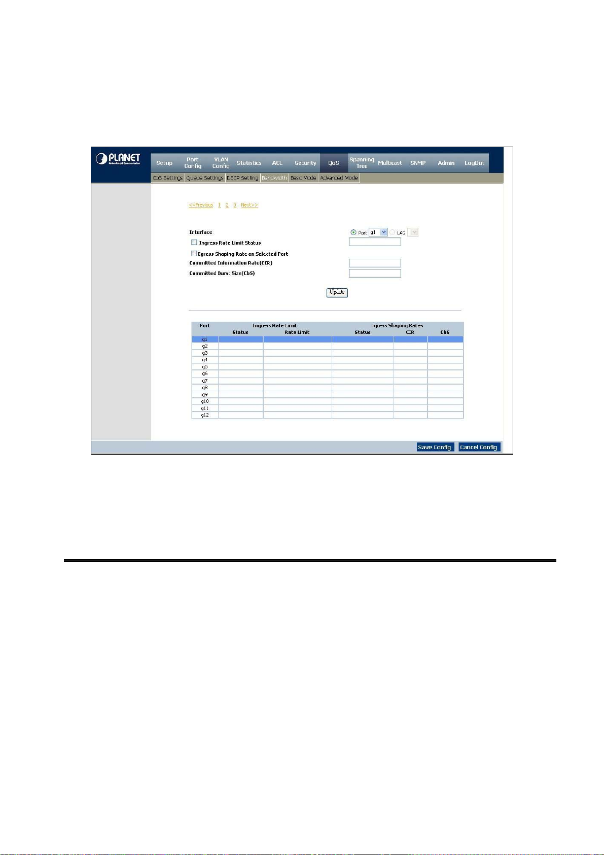
User’s Manual of WGSW-24020/WGSW-48040
4.8.4 Bandwidth
The Bandwidth screen (refer to figure 4-40) allows network managers to define the bandwidth settings for a specified egress
interface. Modifying queue scheduling affects the queue settings globally. The Bandwidth screen is not used with the Service
mode, as bandwidth settings are based on services.
Figure 4-40 Bandwidth screen
Queue shaping can be based per queue and/or per interface. Shaping is determined by the lower specified value. The queue
shaping type is selected in the Bandwidth screen, include interface, port, LAG, Rate Limit, Ingress Rate Limit Status, Rate
Limit….
The page contains the following fields:
Interface
Ingress Rate Limit Status
Rate Limit (62-1000000
Kbps)
Egress Shaping Rate on
Selected Port
Indicates the interface for which the queue shaping information is displayed. The possible
field values are:
• Port, indicates the port for which the bandwidth settings are displayed.
• LAG, indicates the LAG for which the bandwidth settings are displayed.
which indicates if rate limiting is defined on the interface.
Defines the amount of bandwidth assigned to the interface.
The possible field values are 62-1000000 Kbps.
Indicates if rate limiting is enabled on the interface.
-86-
Page 87

User’s Manual of WGSW-24020/WGSW-48040
Committed Information
Rate (CIR)
Defines CIR as the queue shaping type.
The possible field value is 64 - 1,000,000 Kbps.
4.8.5 Basic Mode
The Basic Mode screen (see figure 4-41) contains the following fields:
The page contains the following fields:
Trust Mode
Displays the trust mode. If a packet’s CoS tag and DSCP tag are mapped to
different queues, the Trust Mode determines the queue to which the packet is
assigned. Possible values are:
• CoS, which sets trust mode to CoS on the device and the CoS mapping
• DSCP, sets trust mode to the DSCP on the device. The DSCP mapping
Figure 4-41 Basic Mode screen
determined the packet queue.
determines the packet queue.
-87-
Page 88

User’s Manual of WGSW-24020/WGSW-48040
4.8.6 Advanced Mode
Advanced QoS mode (see figure 4-42) provides rules for specifying flow classification and assigning rule actions that relate to
bandwidth management. The rules are based on the Access Control Lists (see Access Control Tab).
Figure 4-42 Advance Mode screen
MAC A CL s and IP ACLs can be grouped together in more complex structures, called policies. Policies can be applied to an
interface. Policy ACLs are applied in the sequence they appear within the policy. Only a single policy can be attached to a port.
In advanced QoS mode, ACLs can be applied directly to an interface in the Security -ACL Binding. However, a policy and ACL
cannot be simultaneously applied to an interface.
After assigning packets to a specific queue, services such as configuring output queues for the scheduling scheme, or
configuring output shaping for burst size, CIR, or CBS per interface or per queue, can be applied.
Out of Profile DSCP Assignments, this button opens up the DSCP Map screen. (See figure 4-43):
-88-
Page 89

User’s Manual of WGSW-24020/WGSW-48040
Figure 4-43 Out of Profile DSCP Assignments screen
The page contains the following fields:
DSCP In
DSCP Out
The Policy Settings button opens the Policy Name screen (see figure 4-44):
This displays the DSCP In value. The value is form 0-63.
This displays the current DSCP out value. A new value can be selected from the
pull-down menu.
Figure 4-44 Policy Settings screen
-89-
Page 90

The page contains the following fields:
User’s Manual of WGSW-24020/WGSW-48040
Policy Name
Add to List
Select Policy
New Policy Name
Class Map
Defines a new Policy name.
This button will add the policy to the Policy Name table.
This selects an existing Policy by name.
Which defines a new Policy name.
Where selects an existing Class Map by name.
-90-
Page 91

User’s Manual of WGSW-24020/WGSW-48040
Class Map setting
New Class Map, by which the New Class Map button opens the New Class Map screen (see figure 4-45)
The page contains the following fields:
Class Map Name
Preferred ACL
IP ACL
Match
defines a new Class Map name.
which indicates if packets are first matched to an IP based ACL or a MAC based
ACL, the possible field values are:
Matches packets to IP based ACLs first, and then matches packets to MAC based
ACLs.
Criteria used to match IP addresses and /or MAC addresses with an ACL’s
address. The possible field values are:
• And, both the MAC-based and the IP-based ACL must match a packet.
Figure 4-45 Class Map Settings screen
• IP Based ACLs, matches packets to IP based ACLs first, then matches
packets to MAC based ACLs.
• MAC Based ACLs, matches packets to MAC based ACLs first, then matches
packets to IP based ACLs.
• Or, either the MAC-based or the IP-based ACL must match a packet.
MAC A CL
Matches packets to MAC based ACLs and to IP based ACLs.
-91-
Page 92

User’s Manual of WGSW-24020/WGSW-48040
Aggregate Policer, where user-defined aggregate policers. The Aggregate Policer button opens the New Aggregate Policer
screen.
Aggregate Policer Setting
New Aggregate Policer screen (see figure 4-46):
The page contains the following fields:
Aggregate Policer Name
Ingress Committed
Information Rate (CIR)
Ingress Committed Burst
Size (CBS)
Exceed Action
Where enter a name in this field.
This defines the CIR in bits per second. This field is only relevant when the Police
value is Single.
This defines the CBS in bytes per second. This field is only relevant when the
Police value is Single.
Action assigned to incoming packets exceeding the CIR.
This field is only relevant when the Police value is Single. Possible values are:
• Drop, which drops packets exceeding the defined CIR value.
• Remark DSCP, where remarks packet’s DSCP values exceeding the defined
• None, forwarding packets exceeding the defined CIR value.
Figure 4-46 Aggregate Policer Settings screen
CIR value.
-92-
Page 93

User’s Manual of WGSW-24020/WGSW-48040
4.9. Spanning Tree
■ Theory of Spanning Tree Protocol
The IEEE 802.1D Spanning Tree Protocol and IEEE 802.1W Rapid Spanning Tree Protocol allow for the blocking of links
between switches that form loops within the network. When multiple links between switches are detected, a primary link is
established. Duplicated links are blocked from use and become standby links. The protocol allows for the duplicate links to be
used in the event of a failure of the primary link. Once the Spanning Tree Protocol is configured and enabled, primary links are
established and duplicated links are blocked automatically. The reactivation of the blocked links (at the time of a primary link
failure) is also accomplished automatically without operator intervention.
This automatic network reconfiguration provides maximum uptime to network users. However, the concepts of the Spanning
Tree Algorithm and protocol are a complicated and complex subject and must be fully researched and understood. It is possible
to cause serious degradation of the performance of the network if the Spanning Tree is incorrectly configured. Please read the
following before making any changes from the default values.
The Switch STP performs the following functions:
。 Creates a single spanning tree from any combination of switching or bridging elements.
。 Creates multiple spanning trees – from any combination of ports contained within a single switch, in user specified groups.
。 Automatically reconfigures the spanning tree to compensate for the failure, addition, or removal of any element in the tree.
。 Reconfigures the spanning tree without operator intervention.
Bridge Protocol Data Units
For STP to arrive at a stable network topology, the following information is used:
。 The unique switch identifier.
。 The path cost to the root associated with each switch port.
。 The por tidentifier.
STP communicates between switches on the network using Bridge Protocol Data Units (BPDUs). Each BPDU contains the
following information:
。 The unique identifier of the switch that the transmitting switch currently believes is the root switch.
。 The path cost to the root from the transmitting port.
。 The port identifier of the transmitting port.
The switch sends BPDUs to communicate and construct the spanning-tree topology. All switches connected to the LAN on
which the packet is transmitted will receive the BPDU. BPDUs are not directly forwarded by the switch, but the receiving switch
uses the information in the frame to calculate a BPDU, and, if the topology changes, initiates a BPDU transmission.
The communication between switches via BPDUs results in the following:
。 One switch is elected as the root switch.
。 The shortest distance to the root switch is calculated for each switch.
。 A designated switch is selected. This is the switch closest to the root switch through which packets will be forwarded to the
root.
。 A port for each switch is selected. This is the port providing the best path from the switch to the root switch.
。 Ports included in the STP are selected.
-93-
Page 94

User’s Manual of WGSW-24020/WGSW-48040
Creating a Stable STP Topology
It is to make the root port a fastest link. If all switches have STP enabled with default settings, the switch with the lowest MAC
address in the network will become the root switch. By increasing the priority (lowering the priority number) of the best switch,
STP can be forced to select the best switch as the root switch.
When STP is enabled using the default parameters, the path between source and destination stations in a switched network
might not be ideal. For instance, connecting higher-speed links to a port that has a higher number than the current root port can
cause a root-port change.
STP Port States
The BPDUs take some time to pass through a network. This propagation delay can result in topology changes where a port that
transitioned directly from a Blocking state to a Forwarding state could create temporary data loops. Ports must wait for new
network topology information to propagate throughout the network before starting to forward packets. They must also wait for
the packet lifetime to expire for BPDU packets that were forwarded based on the old topology. The forward delay timer is used to
allow the network topology to stabilize after a topology change. In addition, STP specifies a series of states a port must
transition through to further ensure that a stable network topology is created after a topology change.
Each port on a switch using STP exists is in one of the following five states:
。 Blocking – the port is blocked from forwarding or receiving packets.
。 Listening – the port is waiting to receive BPDU packets that may tell the port to go back to the blocking state.
。 Learning – the port is adding addresses to its forwarding database, but not yet forwarding packets.
。 Forwarding – the port is forwarding packets.
。 Disabled – the port only responds to network management messages and must return to the blocking state first.
A port transitions from one state to another as follows:
。 From initialization (switch boot) to blocking.
。 From blocking to listening or to disabled.
。 From listening to learning or to disabled.
。 From learning to forwarding or to disabled.
。 From forwarding to disabled.
。 From disabled to blocking.
-94-
Page 95
User’s Manual of WGSW-24020/WGSW-48040
Switch
Blocking
Listening
Learning
Forwarding
STP Port State Transitions
You can modify each port state by using management software. When you enable STP, every port on every switch in the
network goes through the blocking state and then transitions through the states of listening and learning at power up. If properly
configured, each port stabilizes to the forwarding or blocking state. No packets (except BPDUs) are forwarded from, or received
by, STP enabled ports until the forwarding state is enabled for that port.
2. STP Parameters
STP Operation Levels
The Switch allows for two levels of operation: the switch level and the port level. The switch level forms a spanning tree
Disable
consisting of links between one or more switches. The port level constructs a spanning tree consisting of groups of one or more
ports. The STP operates in much the same way for both levels.
On the switch level, STP calculates the Bridge Identifier for each switch and then sets the Root
#Notice
Bridge and the Designated Bridges. On the port level, STP sets the Root Port and the Designated
Ports.
-95-
Page 96

The following are the user-configurable STP parameters for the switch level:
Parameter Description Default Value
User’s Manual of WGSW-24020/WGSW-48040
Bridge Identifier(Not user
configurable
except by setting priority
below)
Priority
Hello Time
Maximum Age Timer
Forward Delay Timer
A combination of the User-set priority and
the switch’s MAC address.
The Bridge Identifier consists of two parts:
a 16-bit priority and a 48-bit Ethernet MAC
address 32768 + MAC.
A relative priority for each switch – lower
numbers give a higher priority and a greater
chance of a given switch being elected as
the root bridge.
The length of time between broadcasts of
the hello message by the switch.
Measures the age of a received BPDU for a
port and ensures that the BPDU is discarded
when its age exceeds the value of the
maximum age timer.
The amount time spent by a port in the
learning and listening states waiting for a
32768 + MAC
32768
2 seconds
20 seconds
15 seconds
The following are the user-configurable STP parameters for the port or port group level:
Variable Description Default Value
Port Priority
Port Cost
A relative priority for each
port –lower numbers give a higher priority
and a greater chance of a given port being
elected as the root port.
A value used by STP to evaluate paths –
STP calculates path costs and selects the
path with the minimum cost as the active
path.
BPDU that may return the port to the
blocking state.
32768
19-100Mbps Fast Ethernet ports
4-1000Mbps Gigabit Ethernet ports
-96-
Page 97

User’s Manual of WGSW-24020/WGSW-48040
Default Spanning-Tree Configuration
Feature Default Value
Enable state STP enabled for all ports
Port priority 128
Port cost 19
Bridge Priority 32,768
User-Changeable STA Parameters
The Switch’s factory default setting should cover the majority of installations. However, it is advisable to keep the default settings
as set at the factory; unless, it is absolutely necessary. The user changeable parameters in the Switch are as follows:
Priority – A Priority for the switch can be set from 0 to 65535. 0 is equal to the highest Priority.
Hello Time – The Hello Time can be from 1 to 10 seconds. This is the interval between two transmissions of BPDU packets sent
by the Root Bridge to tell all other Switches that it is indeed the Root Bridge. If you set a Hello Time for your Switch, and it is not
the Root Bridge, the set Hello Time will be used if and when your Switch becomes the Root Bridge.
#Notice
Max. Age – The Max Age can be from 6 to 40 seconds. At the end of the Max Age, if a BPDU has still not been received from
the Root Bridge, your Switch will start sending its own BPDU to all other Switches for permission to become the Root Bridge. If it
turns out that your Switch has the lowest Bridge Identifier, it will become the Root Bridge.
Forward Delay Timer – The Forward Delay can be from 4 to 30 seconds. This is the time any port on the
Switch spends in the listening state while moving from the blocking state to the forwarding state.
#Notice
Port Priority – A Port Priority can be from 0 to 255. The lower the number, the greater the probability the port will be chosen as
the Root Port.
Port Cost – A Port Cost can be set from 0 to 65535. The lower the number, the greater the probability the port will be chosen to
forward packets.
3. Illustration of STP
The Hello Time cannot be longer than the Max. Age. Otherwise, a configuration error will occur.
Observe the following formulas when setting the above parameters:
Max. Age _ 2 x (Forward Delay - 1 second)
Max. Age _ 2 x (Hello Time + 1 second)
A simple illustration of three switches connected in a loop is depicted in Figure 5-7. In this example, you can anticipate some
major network problems if the STP assistance is not applied. If switch A broadcasts a packet to switch B, switch B will broadcast
it to switch C, and switch C will broadcast it to back to switch A ... and so on. The broadcast packet will be passed indefinitely in
a loop, potentially causing a network failure. In this example, STP breaks the loop by blocking the connection between switch B
and C. The decision to block a particular connection is based on the STP calculation of the most current Bridge and Port
settings. Now, if switch A broadcasts a packet to switch C, then switch C will drop the packet at port 2 and the broadcast will end
there. Setting-up STP using values other than the defaults, can be complex. Therefore, you are advised to keep the default
factory settings and STP will automatically assign root bridges/ports and block loop connections. Influencing STP to choose a
particular switch as the root bridge using the Priority setting, or influencing STP to choose a particular port to block using the
-97-
Page 98

Port Priority and Port Cost settings is, however, relatively straight forward.
LAN 1
Portcast = 19
Port 3
A
Bridge ID = 15
User’s Manual of WGSW-24020/WGSW-48040
Port 1
Portcast = 4
Portcast = 4
Port 1
B
Bridge ID = 30
Port 2
Port 3
Portcast = 19 Portcast = 19
LAN 2 LAN 3
Before Applying the STA Rules
In this example, only the default STP values are used.
Portcast = 19
LAN 1
Port 2
Portcast = 4
Portcast = 4
C
Port 2
Port 1
Bridge ID = 20
Port 3
Port 3
A
Root Bridge
Blocked
Port 2
Designated Port
Root Port
C
Designated Bridge
Port 2
Port 1
Port 3
Port 1
Designated Port
Root Port
Port 1
B
Port 2
Port 3
LAN 2 LAN 3
After Applying the STA Rules
The switch with the lowest Bridge ID (switch C) was elected the root bridge, and the ports were selected to give a high port cost
between switches B and C. The two (optional) Gigabit ports (default port cost = 4) on switch A are connected to one (optional)
Gigabit port on both switch B and C. The redundant link between switch B and C is deliberately chosen as a 100 Mbps Fast
Ethernet link (default port cost = 19). Gigabit ports could be used, but the port cost should be increased from the default to
-98-
Page 99

User’s Manual of WGSW-24020/WGSW-48040
ensure that the link between switch B and switch C is the blocked link.
■ Supported Spanning Tree Protocol of WGSD Series Switch
Spanning Tree Protocol (STP) provides tree topography for any arrangement of bridges. STP also provides one path between
end stations on a network, eliminating loops.
Loops occur when alternate routes exist between hosts. Loops in an extended network can cause bridges to forward traffic
indefinitely, resulting in increased traffic and reducing network efficiency.
The device supports the following Spanning Tree versions:
• Classic STP, by which provides a single path between end stations, avoiding and eliminating loops.
• Rapid STP, which detects and uses network topologies that provide faster convergence of the spanning tree, without
creating forwarding loops.
• Multiple STP, which provides full connectivity for packets allocated to any VLAN. Multiple STP is based on the RSTP. In
addition, Multiple STP transmits packets assigned to different VLANs through different MST regions. MST regions act as a
single bridge.
4.9.1 STP Status
The STP Status screen (see figure 4-47) describes the STP status on the device.
The page contains the following fields:
Spanning Tree State
By which indicates if STP is enabled on the device.
Figure 4-47 STP Status screen
Spanning Tree Mode
Bridge ID
Designated Root
Root Port
Root Path Cost
By which indicates the STP mode by which STP is enabled on the device.
Where identifies the Bridge priority and MAC address.
This indicates the ID of the bridge with the lowest path cost to the instance ID.
Where indicates the port number that offers the lowest cost path from this bridge to
the Root Bridge. It is significant when the Bridge is not the Root. The default is 0.
Where the cost of the path from this bridge to the root.
-99-
Page 100

User’s Manual of WGSW-24020/WGSW-48040
Root Maximum Age
(sec)
Root Hello Time (sec)
Root Forward delay
(sec)
Topology Changes
Counts
Last Topology Change
4.9.2 The Global STP
This indicates the device Maximum Age Time. The Maximum Age Time indicates
the amount of time in seconds a bridge waits before sending configuration
messages. The default max age is 20 seconds. The range is 6 to 40 seconds.
This indicates the device Hello Time. The Hello Time indicates the amount of time
in seconds a root bridge waits between configuration messages. The default is 2
seconds. The range is 1 to 10 seconds.
This indicates the device forward delay time. The Forward Delay Time indicates the
amount of time in seconds a bridge remains in a listening and learning state before
forwarding packets. The default is 15 seconds. The range is 4 to 30 seconds.
This indicates the total amount of STP state changes that have occurred.
Which indicates the amount of time that has elapsed since the bridge was initialized
or reset, and the last topographic change occurred. The time is displayed in a day
hour minute second format, for example, 2 days 5 hours 10 minutes and 4 seconds.
The Global STP screen (see figure 4-48) contains parameters for enabling STP on the device.Global Setting Spanning Tree
State, which indicates if STP is enabled on the device.
Figure 4-48 Global STP screen
-10
 Loading...