

Page 1
User’s Manual of WGSW Series Managed Switch
1
L2+ Gigabit Ethernet Managed Switch
WGSW-20160HP/WGSW-24040 Series
Page 2

User’s Manual of WGSW Series Managed Switch
2
Trademarks
Copyright © PLANET Technology Corp. 2021.
Contents are subject to revision without prior notice.
PLANET is a registered trademark of PLANET Technology Corp. All other trademarks belong to their respective owners.
Disclaimer
PLANET Technology does not warrant that the hardware will work properly in all environments and applications, and makes no
warranty and representation, either implied or expressed, with respect to the quality, performance, merchantability, or fitness for
a particular purpose. PLANET has made every effort to ensure that this User's Manual is accurate; PLANET disclaims liability
for any inaccuracies or omissions that may have occurred.
Information in this User's Manual is subject to change without notice and does not represent a commitment on the part of
PLANET. PLANET assumes no res pon sib ili ty for any inaccuracies that may be contained in this User's Manual. PLAN ET makes
no commitment to update or keep current t he information in this User' s Manual, and reserves t he r ight to make improvements to
this User's Manual and/or to the products described in this User's Manual, at any time without notice.
If you find information in this manual that is incorrect, misleading, or incomplete, we would appreciate your comments and
suggestions.
FCC Warning
This equipment has been tested and found to comply with the limits for a Class A digital device, pursuant to Part 15 of the FCC
Rules. These limits are de sig n ed to prov ide reasonable protection aga inst har m ful i nter fe re nce when the equipment is operated
in a commercial environment. This equipment generates, uses, and can radiate radio frequency energy and, if not installed and
used in accordance with the Instruction manual, may cause harmful interference to radio communications. Operation of this
equipment in a residential area is likely to cause harmful interference in which case the user will be required to correct the
interference at his own expense.
CE Mark Warning
This is a Class A product. In a domestic environment, this product may cause radio interference, in which case the user may be
required to take adequate measures.
Energy Saving Note of the Device
This power required device does not support Standby mode operation. For energy saving, please remove the power cable to
disconnect the device from the power circuit. In view of saving the energy and reducing the unnecessary power consumption, it
is strongly suggested to remove the power connection for the device if this device is not intended to be active.
WEEE Warning
To avoid the potential effects on the environment and human health as a result of the presence of
hazardous substances in electrical and electronic equipment, end users of electrical and electronic
equipment should understand the meaning of the crossed-out wheeled bin symbol. Do not dispose of
WEEE as unsorted municipal waste and have to collect such WEEE separately.
Revision
PLANET WGSW-20160HP and WGSW-24040 Series Managed Switch User's Manual
Models: WGSW-20160HP(V3)/WGSW-24040/WGSW24040R(V4)/WGSW-24040HP/WGSW-24040HP4(V3)
Revision: WGSW-20160HP(V3)/WGSW-24040/WGSW24040R(V4)/WGSW-24040HP/WGSW-24040HP4(V3) (January, 2021)
Part No: EM-WGSW Managed Switch Series_v3.2
Page 3

User’s Manual of WGSW Series Managed Switch
3
TABLE OF CONTENTS
1. INTRODUCTION .................................................................................................................. 10
1.1 Packet Contents ........................................................................................................................................... 10
1.2 Product Description ...................................................................................................................................... 11
1.3 How to Use This Manual .............................................................................................................................. 17
1.4 Product Features .......................................................................................................................................... 18
1.5 Product Specifications .................................................................................................................................. 24
2. INSTALLATION ................................................................................................................... 30
2.1 Hardware Description ................................................................................................................................... 30
2.1.1 Switch Front Panel .............................................................................................................................................. 30
2.1.2 LED Indications ................................................................................................................................................... 32
2.1.3 Switch Rear Panel ............................................................................................................................................... 35
2.2 Installing the Switch ...................................................................................................................................... 37
2.2.1 Desktop Installation ............................................................................................................................................. 37
2.2.2 Rack Mounting ..................................................................................................................................................... 38
2.2.3 Installing the SFP/SFP+ Transceiver ................................................................................................................... 39
3. SWITCH MANAGEMENT .................................................................................................... 42
3.1 Requirements ............................................................................................................................................... 42
3.2 Management Access Overview .................................................................................................................... 43
3.3 Administration Console ................................................................................................................................. 44
3.4 Web Management ........................................................................................................................................ 45
3.5 SNMP-based Network Management ............................................................................................................ 46
3.6 PLANET Smart Discovery Utility .................................................................................................................. 46
4. WEB CONFIGURATION ...................................................................................................... 48
4.1 Main Web Page ............................................................................................................................................ 50
4.2 System.......................................................................................................................................................... 52
4.2.1 Management ........................................................................................................................................................ 53
4.2.1.1 System Information.................................................................................................................................... 53
4.2.1.2 IP Configuration ......................................................................................................................................... 54
4.2.1.3 IP Status .................................................................................................................................................... 56
4.2.1.4 ARP Configuration ..................................................................................................................................... 57
4.2.1.5 Users Configuration ................................................................................................................................... 58
4.2.1.6 Privilege Levels ......................................................................................................................................... 61
4.2.1.7 NTP Configuration ..................................................................................................................................... 62
4.2.1.7.1 System Time Correction Manually .......................................................................................................... 64
Page 4

User’s Manual of WGSW Series Managed Switch
4
4.2.1.8 Time C onfi guration .................................................................................................................................... 65
4.2.1.9 UPnP ......................................................................................................................................................... 66
4.2.1.10 DHCP Relay ............................................................................................................................................ 68
4.2.1.11 DHCP Relay Statistics ............................................................................................................................. 69
4.2.1.12 CPU Load ................................................................................................................................................ 71
4.2.1.13 System Log ............................................................................................................................................. 72
4.2.1.14 Detailed Log ............................................................................................................................................ 73
4.2.1.15 Remote Syslog ........................................................................................................................................ 74
4.2.1.16 SMTP Configuration ................................................................................................................................ 75
4.2.2 Simple Network Management Protocol ............................................................................................................... 76
4.2.2.1 SNMP Overview ........................................................................................................................................ 76
4.2.2.2 SNMP System Configuration ..................................................................................................................... 77
4.2.2.3 SNMP System Information ........................................................................................................................ 78
4.2.2.4 SNMP Trap Configuration .......................................................................................................................... 79
4.2.2.5 SNMP Trap Source Configuration ............................................................................................................. 81
4.2.2.6 SNMPv3 Communities .............................................................................................................................. 82
4.2.2.7 SNMPv3 Users .......................................................................................................................................... 83
4.2.2.8 SNMPv3 Groups ....................................................................................................................................... 85
4.2.2.9 SNMPv3 Views .......................................................................................................................................... 86
4.2.2.10 SNMPv3 Access ...................................................................................................................................... 87
4.2.3 RMON ................................................................................................................................................................. 88
4.2.3.1 RMON Alarm Configuration ....................................................................................................................... 88
4.2.3.2 RMON Alarm Status .................................................................................................................................. 90
4.2.3.3 RMON Event Configuration ....................................................................................................................... 91
4.2.3.4 RMON Event Status .................................................................................................................................. 92
4.2.3.5 RMON History Configuration ..................................................................................................................... 93
4.2.3.6 RMON History Status ................................................................................................................................ 94
4.2.3.7 RMON Statistics Configuration .................................................................................................................. 95
4.2.3.8 RMON Statistics Status ............................................................................................................................. 96
4.2.4 DHCP server ....................................................................................................................................................... 98
4.2.4.1 DHCP Server Mode Configuration............................................................................................................. 98
4.2.4.2 DHCP Server excluded IP Configuration ................................................................................................... 99
4.2.4.3 DHCP Server pool Configuration ............................................................................................................. 100
4.2.4.4 DHCP Server pool Statistics .................................................................................................................... 101
4.2.4.5 DHCP Server Binding .............................................................................................................................. 103
4.2.4.6 DHCP Server Declined IP ....................................................................................................................... 104
4.2.4.7 Detailed Statistics .................................................................................................................................... 104
4.2.5 Remote Management ........................................................................................................................................ 105
4.2.5.1 Remote NMS Configuration ..................................................................................................................... 105
4.3 Switching .................................................................................................................................................... 106
4.3.1 Port Management .............................................................................................................................................. 106
Page 5

User’s Manual of WGSW Series Managed Switch
5
4.3.1.1 Port Configuration ................................................................................................................................... 106
4.3.1.2 Port Statistics Overview ........................................................................................................................... 108
4.3.1.3 Port Statistics Detailed ............................................................................................................................ 109
4.3.1.4 SFP Module Information .......................................................................................................................... 111
4.3.1.5 Port Mirror ............................................................................................................................................... 113
4.3.2 Link Aggregation ................................................................................................................................................ 116
4.3.2.1 Common .................................................................................................................................................. 118
4.3.2.2 LACP Configuration ................................................................................................................................. 121
4.3.2.3 LACP System Status ............................................................................................................................... 122
4.3.2.4 LACP Internal Status ............................................................................................................................... 123
4.3.2.5 LACP Neighbor Port Status ..................................................................................................................... 123
4.3.3 VLAN ................................................................................................................................................................. 124
4.3.3.1 VLAN Overview ....................................................................................................................................... 124
4.3.3.2 IEEE 802.1Q VLAN ................................................................................................................................. 125
4.3.3.3 VLAN Port Configuration ......................................................................................................................... 128
4.3.3.4 VLAN Membership Status ....................................................................................................................... 134
4.3.3.5 VLAN Port Status .................................................................................................................................... 135
4.3.3.6 Private VLAN ........................................................................................................................................... 137
4.3.3.7 Port Isolation ........................................................................................................................................... 138
4.3.3.8 VLAN setting example: ............................................................................................................................ 140
4.3.3.8.1 Two Separate 802.1Q VLANs .............................................................................................................. 140
4.3.3.8.2 VLAN Trunking between two 802.1Q aware switches .......................................................................... 143
4.3.3.8.3 Port Isolate ........................................................................................................................................... 145
4.3.3.9 MAC-based VLAN ................................................................................................................................... 146
4.3.3.10 IP Subnet-based VLAN ......................................................................................................................... 147
4.3.3.11 Protocol-based VLAN ............................................................................................................................ 148
4.3.3.12 Protocol-based VLAN Membership ....................................................................................................... 150
4.3.4 VLAN Tr ansl atio n ............................................................................................................................................... 151
4.3.4.1 Port to Group Configuration ..................................................................................................................... 151
4.3.4.2 Port to Group Configuration ..................................................................................................................... 152
4.3.5 Spanning Tree Protocol ..................................................................................................................................... 154
4.3.5.1 Theory ..................................................................................................................................................... 154
4.3.5.2 STP System Configuration ...................................................................................................................... 160
4.3.5.3 Bridge Status ........................................................................................................................................... 162
4.3.5.4 CIST Port Configuration .......................................................................................................................... 163
4.3.5.5 MSTI Priorities ......................................................................................................................................... 166
4.3.5.6 MSTI Configuration.................................................................................................................................. 167
4.3.5.7 MSTI Ports Configuration ........................................................................................................................ 168
4.3.5.8 Port Status ............................................................................................................................................... 170
4.3.5.9 Port Statistics .......................................................................................................................................... 171
4.3.6 Multicast ............................................................................................................................................................ 172
Page 6

User’s Manual of WGSW Series Managed Switch
6
4.3.6.1 IGMP Snooping ....................................................................................................................................... 172
4.3.6.2 Profile Table .................................................................................................................................................... 176
4.3.6.3 Address Entry .......................................................................................................................................... 177
4.3.6.4 IGMP Snooping Configuration ................................................................................................................. 179
4.3.6.5 IGMP Snooping VLAN Configuration ....................................................................................................... 181
4.3.6.6 IGMP Snooping Port Group Filtering ....................................................................................................... 183
4.3.6.7 IGMP Snooping Status ............................................................................................................................ 184
4.3.6.8 IGMP Group Information ......................................................................................................................... 185
4.3.6.9 IGMPv3 Information................................................................................................................................. 186
4.3.7 MLD Snooping ................................................................................................................................................... 187
4.3.7.1 MLD Snooping Configuration .................................................................................................................. 187
4.3.7.2 MLD Snooping VLAN Configuration ........................................................................................................ 188
4.3.7.3 MLD Snooping Port Group Filtering ........................................................................................................ 190
4.3.7.4 MLD Snooping Status.............................................................................................................................. 191
4.3.7.5 MLD Group Information ........................................................................................................................... 192
4.3.7.6 MLDv2 Information .................................................................................................................................. 193
4.3.8 MVR (Multicast VLAN Registration) ................................................................................................................... 194
4.3.8.1 MVR Configuration .................................................................................................................................. 195
4.3.8.2 MVR Status ............................................................................................................................................. 197
4.3.8.3 MVR Groups Information ......................................................................................................................... 198
4.3.8.4 MVR SFM Information ............................................................................................................................. 199
4.3.9 LLDP ................................................................................................................................................................. 200
4.3.9.1 Link Layer Discovery Protocol ................................................................................................................. 200
4.3.9.2 LLDP Configuration ................................................................................................................................. 200
4.3.9.3 LLDP Neighbors ...................................................................................................................................... 203
4.3.9.4 LLDP MED Configuration ........................................................................................................................ 205
4.3.9.5 LLDP-MED Neighbor ............................................................................................................................... 212
4.3.9.6 Port Statistics .......................................................................................................................................... 216
4.3.10 MAC Address T able ......................................................................................................................................... 218
4.3.10.1 MAC Table Configuration ....................................................................................................................... 218
4.3.10.2 MAC Address Table Status .................................................................................................................... 220
4.3.11 Loop Protection ................................................................................................................................................ 222
4.3.11.1 Configuration ......................................................................................................................................... 222
4.3.11.2 Loop Protection Status .......................................................................................................................... 223
4.3.12 UDLD ............................................................................................................................................................... 224
4.3.12.1 UDLD Port Configuration ....................................................................................................................... 224
4.3.12.2 UDLD Status ......................................................................................................................................... 225
4.3.13 GVRP .............................................................................................................................................................. 227
4.3.13.1 GVRP Configuration .............................................................................................................................. 227
4.3.13.2 GVRP Port Configuration ...................................................................................................................... 229
4.4 Quality of Service ....................................................................................................................................... 230
Page 7

User’s Manual of WGSW Series Managed Switch
7
4.4.1 General .............................................................................................................................................................. 230
4.4.1.1 QOS Port Classification ........................................................................................................................... 231
4.4.1.2 Queue Policing ........................................................................................................................................ 232
4.4.1.3 Port Tag Remarking ................................................................................................................................. 233
4.4.1.4 Statistics ......................................................................................................................................................... 235
4.4.2 Bandwidth Control ............................................................................................................................................. 236
4.4.2.1 Port Policing ............................................................................................................................................ 236
4.4.2.2 Port Schedule .......................................................................................................................................... 237
4.4.2.3 Port Shaping ............................................................................................................................................ 239
4.4.3 Storm Control .................................................................................................................................................... 241
4.4.3.1 Storm Policing Configuration ................................................................................................................... 241
4.4.4 Differentiated Service ........................................................................................................................................ 242
4.4.4.1 Port DSCP ............................................................................................................................................... 242
4.4.4.2 DSCP-based QoS ................................................................................................................................... 243
4.4.4.3 DSCP Translation .................................................................................................................................... 244
4.4.4.4 DSCP Classification ................................................................................................................................ 246
4.4.5 QCL ................................................................................................................................................................... 247
4.4.5.1 QoS Control List ...................................................................................................................................... 247
4.4.5.2 QCL Status .............................................................................................................................................. 251
4.4.5.3 Voice VLAN Configuration ....................................................................................................................... 253
4.4.5.4 Voice VLAN OUI Table ............................................................................................................................ 255
4.5 Security....................................................................................................................................................... 256
4.5.1 Access Security ................................................................................................................................................. 256
4.5.1.1 Access Management ............................................................................................................................... 256
4.5.1.2 Access Management Statistics ................................................................................................................ 257
4.5.1.3 SSH ......................................................................................................................................................... 258
4.5.1.4 HTTPs ..................................................................................................................................................... 259
4.5.2 AAA ................................................................................................................................................................... 261
4.5.2.1 Authenticatio n Method ............................................................................................................................. 266
4.5.2.2 RADIUS ................................................................................................................................................... 268
4.5.2.3 TACACS+ ................................................................................................................................................ 270
4.5.2.4 RADIUS Overview ................................................................................................................................... 272
4.5.2.5 RADIUS Details ....................................................................................................................................... 274
4.5.3 Port Authentication ............................................................................................................................................ 281
4.5.3.1 Network Access Server Configuration ..................................................................................................... 281
4.5.3.2 Network Access Overview ....................................................................................................................... 285
4.5.4 Port Security ...................................................................................................................................................... 291
4.5.4.1 Port Limit Control ..................................................................................................................................... 291
4.5.4.2 Port Security Status ................................................................................................................................. 294
4.5.4.3 Port Security Detail .................................................................................................................................. 296
4.5.5 Access Control Lists .......................................................................................................................................... 297
Page 8

User’s Manual of WGSW Series Managed Switch
8
4.5.5.1 Access Control List Status ....................................................................................................................... 297
4.5.5.2 Access Control List Configuration ............................................................................................................ 299
4.5.5.3 ACE Configuration ................................................................................................................................... 301
4.5.5.4 ACL Port Configuration ............................................................................................................................ 312
4.5.5.5 ACL Rate Limiters .................................................................................................................................... 314
4.5.6 DHCP Snooping ................................................................................................................................................ 315
4.5.6.1 DHCP Snooping Configuration ................................................................................................................ 316
4.5.6.2 Dynamic DHCP Snooping Table .............................................................................................................. 317
4.5.7 IP Source Guard ................................................................................................................................................ 318
4.5.7.1 IP Source Guard Configuration................................................................................................................ 318
4.5.7.2 IP Source Guard Static Table .................................................................................................................. 319
4.5.7.3 Dynamic IP Source Guard Table..................................................................................................................... 320
4.5.8 ARP Inspection .................................................................................................................................................. 321
4.5.8.1 ARP Inspection ........................................................................................................................................ 321
4.5.8.2 ARP Inspection Static Table..................................................................................................................... 322
4.5.8.3 Dynamic ARP Inspection Table ................................................................................................................ 324
4.6 Power over Ethernet (For WGSW-20160HP/WGSW-24040HP_24040HP4) ............................................ 325
4.6.1 PoE .................................................................................................................................................................... 325
4.6.1.1 Power over Ethernet Powered Device ..................................................................................................... 326
4.6.1.2 System Configuration .............................................................................................................................. 327
4.6.1.3 Power over Ethernet Configuration ......................................................................................................... 328
4.6.1.4 Port Configuration ................................................................................................................................... 329
4.6.1.5 PoE Status .............................................................................................................................................. 331
4.6.1.6 Port Sequential ........................................................................................................................................ 333
4.6.1.7 PoE Schedule .......................................................................................................................................... 334
4.6.1.8 PoE Alive Check Configuration ................................................................................................................ 337
4.6.1.9 Port Power Consumption ......................................................................................................................... 340
4.6.1.10 LLDP PoE Neighbors ............................................................................................................................ 340
4.7 ONVIF......................................................................................................................................................... 342
4.7.1 ONVIF ............................................................................................................................................................... 342
4.7.1.1 ONVIF Device Search ............................................................................................................................. 342
4.7.1.2 ONVIF Device List ................................................................................................................................... 344
4.7.1.3 MAP Upload / Edit ................................................................................................................................... 345
4.7.1.4 Floor Map ................................................................................................................................................ 346
4.8 Maintenance ............................................................................................................................................... 347
4.8.1 Web Firmware Upgrade ..................................................................................................................................... 347
4.8.2 Save Startup Config .......................................................................................................................................... 348
4.8.3 Configuration Download .................................................................................................................................... 348
4.8.4 Configuration Upload ......................................................................................................................................... 349
4.8.5 Configure Activate ............................................................................................................................................. 350
4.8.6 Configure Delete ................................................................................................................................................ 350
Page 9

User’s Manual of WGSW Series Managed Switch
9
4.8.7 Image Select ...................................................................................................................................................... 351
4.8.8 Factory Default .................................................................................................................................................. 352
4.8.9 System Reboot .................................................................................................................................................. 353
4.8.10 Ping ................................................................................................................................................................. 353
4.8.11 IPv6 Ping ......................................................................................................................................................... 355
4.8.12 Remote IP Ping ............................................................................................................................................... 357
4.8.13 Cable Diagnostics ............................................................................................................................................ 358
4.8.14 Tr acero ute (IPv 4) ............................................................................................................................................. 360
4.8.15 Tr acero ute (IPv6) ............................................................................................................................................. 362
5. SWITCH OPERATION ....................................................................................................... 363
5.1 Address Table ............................................................................................................................................. 363
5.2 Learning...................................................................................................................................................... 363
5.3 Forwarding & Filtering ................................................................................................................................ 363
5.4 Store-and-Forward ..................................................................................................................................... 363
5.5 Auto-Negotiation ......................................................................................................................................... 364
APPENDIX A: Networking Connection ............................................................................... 367
A.1 Switch's Data RJ45 Pin Assignments - 1000Mbps, 1000B AS E-T ............................................................. 367
A.2 10/100Mbps, 10/100BASE-TX ................................................................................................................... 367
Page 10
User’s Manual of WGSW Series Managed Switch
10
Model
TP Port
Fiber Port
Combo Port
PoE Budget
WGSW-20160HP
WGSW-24040
24 - 4
-
WGSW-24040R
WGSW-24040HP
24 - 4
220W
WGSW-24040HP4
1. INTRODUCTION
1.1 Packet Contents
Thank you for purchasing PLANET WGSW Managed Gigabit Switch series. The descriptions of the series are shown below:
16 - 4 230W
24 - 4 -
24 - 4 440W
“Managed Switch” is used as an alternative name in this Quick Installation Guide.
Open the box of the Managed Switch and carefully unpack it. The box should contain the following items:
The Managed Switch x 1
Quick Installation Guide x 1
DB9 to RS232 Cable x 1
Rubber Feet x 1
Two Rack-mounting Brackets with Attachment Screws x 1
Power Cord x 1
SFP Dust-proof Caps x 4
If any item is found missing or damaged, please contact your local reseller for replacement.
Page 11
User’s Manual of WGSW Series Managed Switch
11
1.2 Product Description
Perfect Managed Switch with L2+/L4 Switchin g and Security
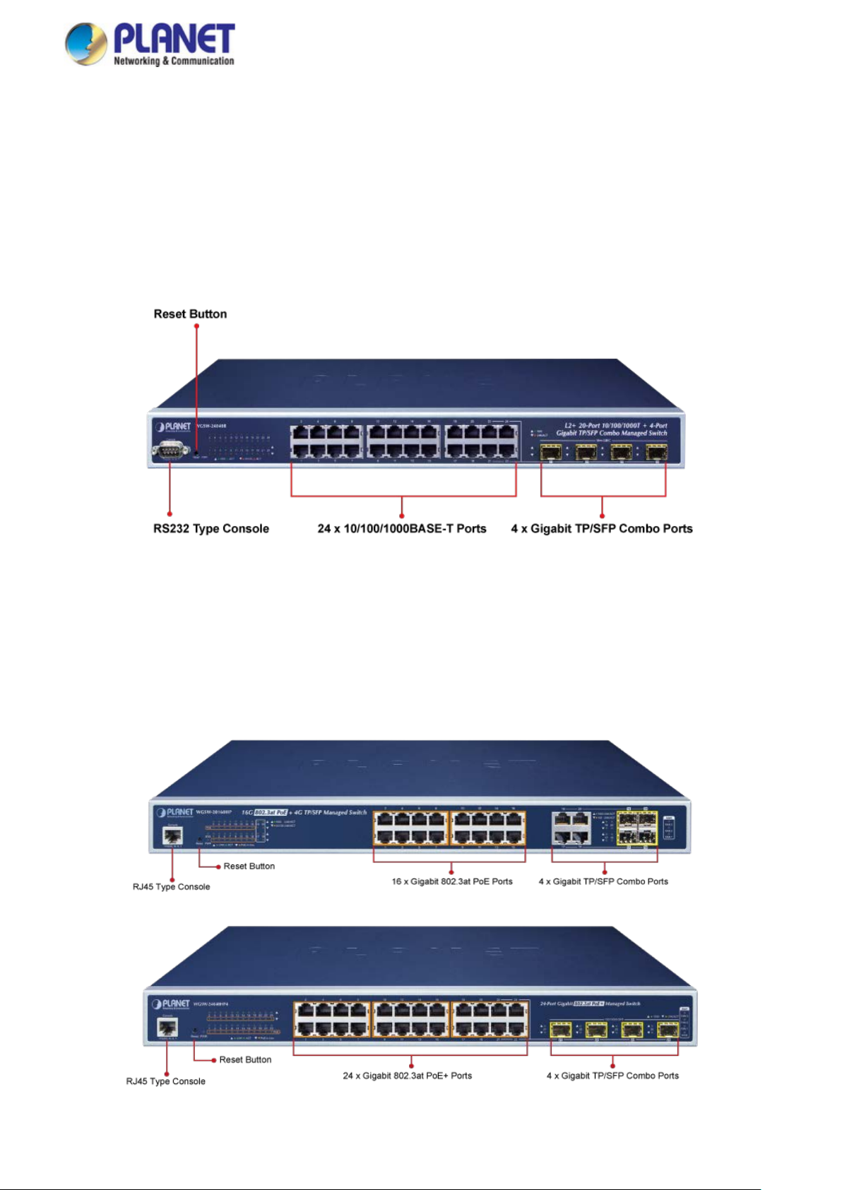
PLANET WGSW-24040 series is a Layer 2+ managed Gigabit Switch that features 24-Por t 10/10 0/1000BASE-T + 4-Port
Shared 100/1000BASE-X SFP and supports static Layer 3 routing for enterprise-level network. The abundan t L2/L4 switching
engine offered by the WGSW-24040 series performs effective data traffic control for enterprises and VoIP service providers,
video streaming, and multicast applications. Providing user-friendly but advanced IPv6/IPv4 management interfaces, it is well
suited for backbone and workgroup network applications by providing affordability, high performance, and stable transmission
quality.
PLANET WGSW-20160HP and WGSW-24040HP4 Layer 2 Managed Gigabit Switch supports both IPv4 and IPv6 protocols
and Layer 3 static routing, and provides 16/24 10/100/1000BASE-T ports featuring 36-watt 802.3at PoE+ and
4 extra Gigabit TP/SFP combo interfaces (WGSW-20160HP), 4 100/1000BASE-X SFP+ fiber ports (WGSW-24040HP4).
Each of the 16/24 Gigabit ports provides 36 watts of power, with a total power budget of up to 220/440 watts for the different
types of PoE applications being employed. It provides a quick, safe and cost-effective Power over Ethernet network solution to
IP security surveillance for small businesses and enterprises.
Page 12
User’s Manual of WGSW Series Managed Switch
12
Network Cybersecurity Network Solution to Minimize Security Risks
The new-generation WGSW Managed Switch series comes with enhanced cybersecurity to fend off cyberthreats and
cyberattacks, it support s SSHv 2, TLS and SSL protocols to provide strong protection ag ainst advance d threat s. Ser ved as a key
point to transmit data to customer's critical equipment in a business network, the cybersecurity feature protects the switch
management and enhances the security of the mission-critical network without any extra deployment cost and effort.
Built-in Unique PoE Functions for Surveillance Management
As a managed PoE Switch for surveillance network, the WGSW-20160HP and WGSW-24040HP4 features the following
intelligent PoE management functions:
PoE Schedule
PD Alive Check
Scheduled Power Recycling
SMTP/SNMP Trap Event Alert
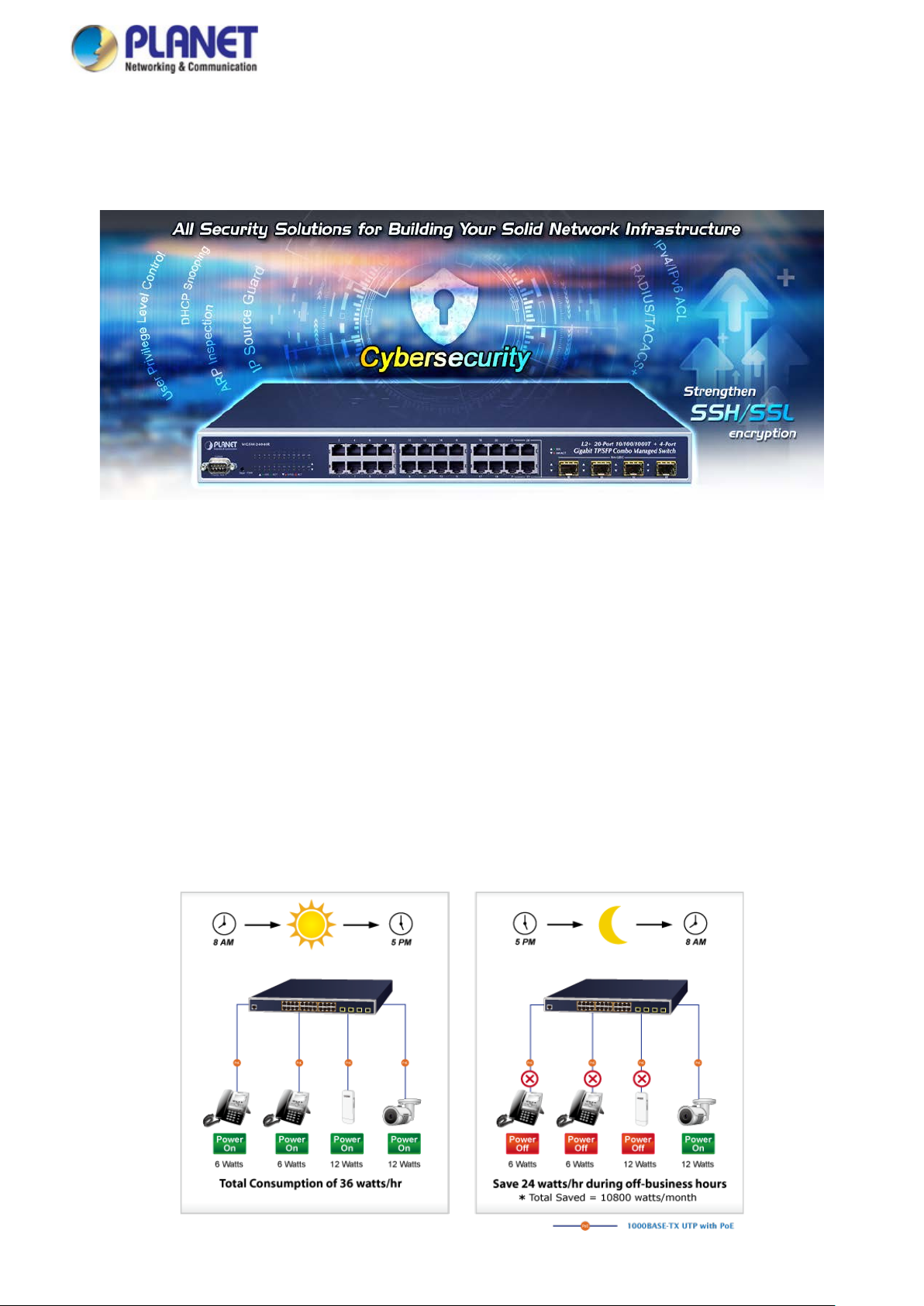
PoE Schedule for Energy Saving
Besides being used for IP surveillance, the WGSW-20160HP and WGSW-24040HP4 is certainly applicable to build any PoE
network including VoIP and wireless LAN. Under the trend of energy saving worldwide and contributing to the environmental
protection on the Earth, the WGSW-20160HP and WGSW-24040HP4 can effectively control the power supply besides its
capability of giving high watts power. The “PoE schedule” function helps you to enable or disable PoE power feeding for each
PoE port during specified time intervals and it is a powerful function to help SMBs and enterprises save energy and budget.
Page 13
User’s Manual of WGSW Series Managed Switch
13
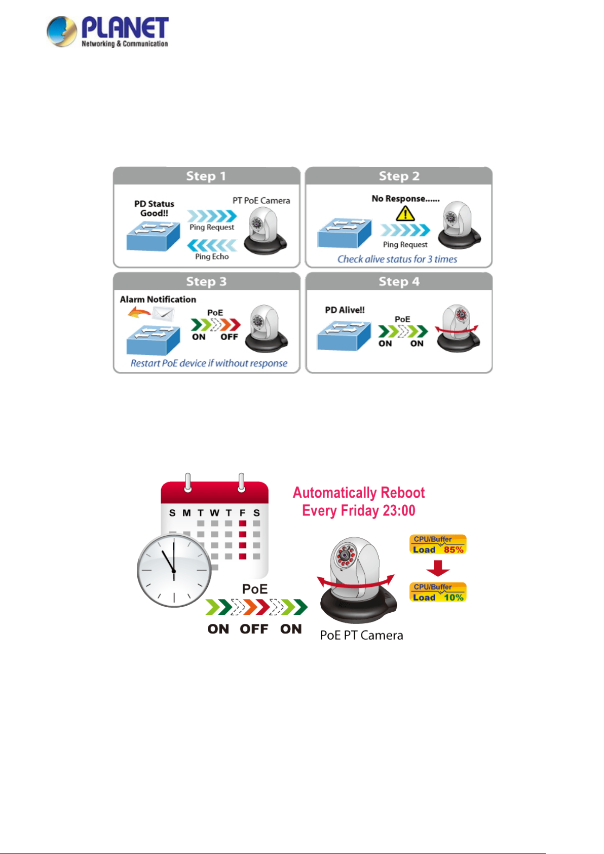
Intelligent Powered Device Alive Check
The WGSW-20160HP and WGSW-24040HP4 can be configured to monitor a connected PD status in real time via ping action.
Once the PD stops working and it is without response, the WGSW-20160HP and WGSW-24040HP4 will resume the PoE port
power and bring the PD back to work. It will greatly enhance the network reliability through the PoE port resetting the PD’s
power source, thus reducing administrator management burden.
Scheduled Power Recycling
The WGSW-20160HP and WGSW-24040HP4 allows each of the connected PDs to reboot at a specified time each week.
Therefore, it will reduce the chance of PD crash result ing fro m buf f er ov erflow.
Page 14
User’s Manual of WGSW Series Managed Switch
14
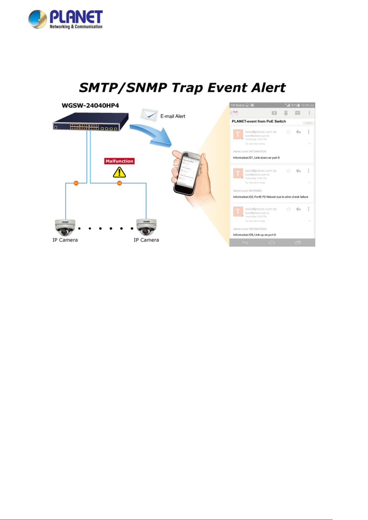
SMTP/SNMP Trap Event Alert
Though most NVR or camera management software offers SMTP email alert function, the WGSW-20160HP and
WGSW-24040HP4 further pr ov ides event alert fun ction to help to d iagnose the a bnormal dev ice owing to w hether or not th ere i s
a break of the network connection, loss of PoE power or the rebooting response by the PD Alive Check process.
Convenient and Smart ONVIF Devices with Detection Feature
PLANET has newly developed an awesome feature -- ONVIF Support -- which is specif ica ll y designed for coop erati ng w ith
video IP surveillance s. Fr om t he WGSW-20160HP and WGSW-24040HP4 GUI, you just need one click to search and show all
of the ONVIF devices via network application. In addition, you can upload floor images to the switch and remotely monito r w hat
is going on in the production line. Moreover, you can get real-time surveillance’s information and online/offline status, and can
have PoE reboot control from GUI.
Solution for IPv6 Networking
With the support for IPv6/IPv4 protocol, and easy and friendly management interfaces, the WGSW Managed Switch series is
the best choice for IP surveillance, VoIP and wireless service providers to connect with the IPv6 network. It also helps SMBs to
step in the IPv6 era with the lowest investment and without having to replace the network facilities even though ISPs establish
the IPv6 FTTx edge network.
IPv4 and IPv6 VLAN Routing for Secure and Flexible Management
To help customers stay on top of their businesses, the WGSW Managed Switch series not only provides ultra high transmission
performance and excellent layer 2 technologies, but also offers IPv4/IPv6 VLAN routing feature which allows to crossover
different VLANs and different IP addresses for the purpose of having a highly-secure, flexible management and simpler
networking application.
Page 15

User’s Manual of WGSW Series Managed Switch
15
Robust Layer 2 Features
The WGSW Managed Switch series can be programmed for advanced switch management function, such as d yn am ic port link
aggregation, Q-in-Q VLAN, Multiple Spanning Tree Protocol (MSTP), Layer 2/4 QoS, bandwidth control and IGMP/MLD
snooping. The GS-5220-8P2T2S allows the operation of a high-speed trunk combining multiple ports. Supporting 10/12 trunk
groups, it enables a maximum of up to 4/16 ports per trunk and supports connection fail-over as well.
Powerful Security
The WGSW Managed Sw itch series offers comprehensive layer 2 to layer 4 access control list (ACL) for enforcing sec urity to
the edge. It can be used to restrict network access by denying packets based on source and destination IP address, TCP/UDP
port number or defined typical network applications. Its protection mechanism also comprises 802.1x Port-based and
MAC-based user and device authentication. W ith the private VLAN function, communication between edge ports can be
prevented to ensure user privacy.
Enhanced Security and Traffic Control
The WGSW Managed Switch series also provides DHCP Snooping, IP Source Guard and Dynamic ARP Inspection
functions to prevent IP snooping from attack and discard ARP packets with invalid MAC address. The netw or k adm ini str at or can
now build highly-secure corporate networks with considerably less time and effort than before.
User-friendly Secure Management
For efficient management, the WGSW Managed Switch series is equipped with console, web and SNMP management
interfaces. With the built-in web-based management interface, the WGSW Managed Switch series offers an easy-to-use,
platform independent man age ment and con figuration facility. The WGSW Managed Switch series supports SNMP and it can be
managed via any management software based on the standard SNMP v1 and v2 protocols. For reducing product learning time,
the W GSW Managed Switch series offers C isco-like command via Telnet or console port and customer doesn’t need to learn
new command from these switches. Moreover, the WGSW Managed Switch series offers remote secure management by
supporting SSH, TLS and SNMPv3 connection which can encrypt the packet content at each session.
Flexible and Extendable Solution
The 4 mini-GBIC SFP slots built in the WGSW Managed Switch series support dual speed as it features 100BASE-FX and
1000BASE-SX/LX SFP (Small Form-factor Pluggable) fiber-optic modules. Now the administrator can flexibly choose the
suitable SFP transceiver according to not only the transmission distance, but also the transmission speed required. The
distance can be extended from 550 meters to 2km (multi-mode fiber) and up to 10/20/40/60/80/120 kilometers (single-mode
fiber or WDM fiber). They are well suited for applications within the enterprise data centers and distributions.
Intelligent SFP Diagnosis Mechanism
The WGSW Managed Switch series supports SFP-DDM (Digital Diagnostic Monitor) function that greatly helps network
administrator to easily monitor real-time parameters of the SFP transceivers, such as optical output power, optical input power,
temperature, laser bias current, and transceiver supply voltage.
Page 16
User’s Manual of WGSW Series Managed Switch
16
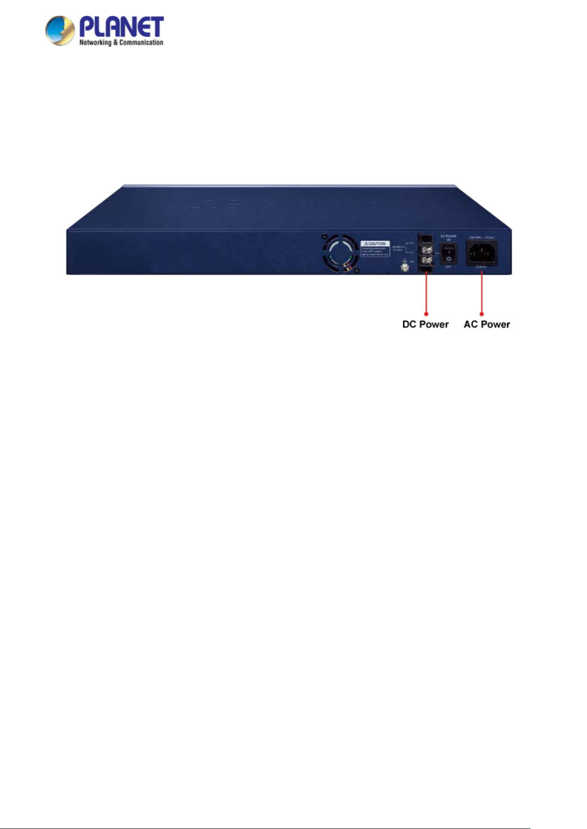
Redundant AC/DC Power Supply to Ensure Continuous Operation
The WGSW-24040R is particularly equipped with one 100~240V AC power supply unit and one 36~60V DC power supply unit
to provide an enhanced reliable and scalable redundant power supply. The continuous power system is specifically designed to
fulfill the demands of high-tech facilities requiring the highest power integrity. With the 36~60V DC power supply, the
WGSW-24040R is able to act as a telecom-level device that can be located in the electronic room.
Page 17

User’s Manual of WGSW Series Managed Switch
17
1.3 How to Use This Manual
This User’s Manual is structured as follows:
Section 2, INSTALLATION
The section explains the functi ons of the Managed Switch and how to physically install the Managed Switch.
Section 3, SWITCH MANAGEMENT
The section contains the i nformation about the software function of the Managed Switch.
Section 4, WEB CONFIGURATION
The section explains how to manage the Managed Switch by Web interface.
Section 5, SWITCH OPERATION
The chapter explains how to do the switch operation of the Managed Switch.
Section 6, TROUBLESHOOTING
The chapter explains how to do troubleshooting of the Managed Switch.
Appendix A
The section contains cable inf or mat ion of the Managed Switch.
Page 18

User’s Manual of WGSW Series Managed Switch
18
1.4 Product Features
WGSW-24040 /WGSW-24040R
Physical Ports
24 10/100/1000BASE-T RJ45 copper ports
4 100/1000BASE-X /SFP slots, shared with Port-21 to Port-24
Console interface for basic management and setup
Layer 2 Features
■ High performance of Store-and-Forward architecture and runt/CRC filtering eliminates erroneous packets to optimize
the network bandwidth
■ Storm Control support
− Broadcast / Multicast / Unknown unicast
■ Supports VLAN
− IEEE 802.1Q tagged VLAN
− Up to 255 VLANs groups, out of 4094 VLAN IDs
− Supports provider bridging (VLAN Q-in-Q, IEEE 802.1ad)
− Private VLAN Edge (PVE)
− Protocol-based VLAN
− MAC-based VLAN
− Voice VLAN
− GVRP (GARP VLAN Registration Protocol)
■ Supports Spanning Tree Protocol
− IEEE 802.1D Spanning Tree Protocol (STP)
− IEEE 802.1w Rapid Spanning Tree Protocol (RSTP)
− IEEE 802.1s Multiple Spanning Tree Protocol (MSTP), spanning tree by VLAN
− BPDU Guard
■ Supports Link Aggregation
− 802.3ad Link Aggregation Control Protocol (LACP)
− Ci sco ether-channel (static trunk)
− Maximum 10 trunk groups, up to 16 ports per trunk group
− Up to 32Gbps bandwidth (full duplex mode)
■ Provides port mirroring (many-to-1)
■ Port mirroring to monitor the incoming or outgoing traffic on a particular port
■ Loop protection to avoid broadcast loops
■ Compatible with Cisco Uni-directional link detection (UDLD) that monitors a link between two switches and blocks
the ports on both ends of the link if the link fails at any point between the two devices.
Quality of Service
■ Ingress Shaper and Egress Rate Limit per port bandwidth control
■ 8 priority queues on all switch ports
■ Traffic classification
- IEEE 802.1p CoS
- TOS / DSCP / IP Precedence of IPv4/IPv6 packets
- IP TCP/UDP port number
- Typical network application
■ Strict priority and Weighted Round Robin (WRR) CoS policies
■ Supports QoS and In/Out bandwidth control on each port
■ Traffic-policing on the switch port
■ DSCP remarking
Page 19

User’s Manual of WGSW Series Managed Switch
19
Multicast
Supports IPv4 IGMP Snooping v1, v2 and v3
Supports IPv6 MLD Snooping v1 and v2
Querier mode support
IPv4 IGMP Snooping port filtering
IPv6 MLD Snooping port filtering
Multicast VLAN Registration (MVR) support
Security
Authentication
- IEEE 802.1x Port-based / MAC-based network access authentication
- Built-in RADIUS client to co-operate with the RADIUS servers
- TACACS+ login users access authentication
- RADIUS / TACACS+ users access authentication
- Guest VLAN assigns clients to a restricted VLAN with limited services
Access Control List
- IP-based Access Control List (ACL)
- MAC-based Access Control List
Source MAC / IP address binding
DHCP Snooping to filter un-trusted DHCP messages
Dynamic ARP Inspection discards ARP packets with invalid MAC address to IP address binding
IP Source Guard prevents IP spoofing attacks
Auto DoS rule to defend DoS attack
IP address access management to prevent unauthorized intruder
Management
IPv4 and IPv6 dual stack management
Switch Management Interfaces
- Console / Telnet Command Line Interface
- Web switch management
- SNMP v1, v2c, and v3 switch management
- SSH / SSL secure access
SNMP Management
- Four RMON groups (history, statistics, alarms, and events)
- SNMP trap for interface Link Up and Link Down notification
IPv6 IP Address / NTP / DNS management
Built-in Trivial File Transfer Protocol (TFTP) client
BOOTP and DHCP for IP address assignment
System Maintenance
- Firmware upload/download via HTTP / TFTP
- Reset button for system reboot or reset to factory default
- Dual Images
DHCP Relay
DHCP Option82
DHCP Server
User Privilege levels control
NTP (Network T ime Protocol)
Link Layer Discovery Protocol (LLDP) and LLDP-MED
Network Diagnostic
Page 20

20
- ICMPv6 / ICMPv4 Remote Ping
- Cable Diagnostic technology provides the mechanism to detect and report potential cabling issues
SMTP / Syslog remote alarm
System Log
PLANET Smart Discovery Uti lity for deploy management
Redundant Power System ( WGSW-24040R)
Redundant 100~240V AC/36-60V DC dual power
Active-active redundant power failure protection
Backup of catastrophic power failure on one supply
Fault tolerance and resilience
User’s Manual of WGSW Series Managed Switch
Page 21

User’s Manual of WGSW Series Managed Switch
21
WGSW-20160HP/ WGSW-24040HP4
Physical Port
16/24-port 10/100/1000BASE-T RJ45 copper with 802.3at PoE+ injector function
4 10/100/1000Mbps TP and SFP shared combo interfaces, supporting 100/1000Mbps dual mode, shared with
Ports 17 to 20 (WGSW-20160HP)
4 100/1000BASE-X mini-GBIC/SFP ports, shared with port-21 to port-24 (WGSW-24040HP4)
RS232 RJ45 console interface for switch basic ma nag eme nt and setu p
Power over Ethernet
Complies with IEEE 802.3at Power over Ethernet Plus/end-span PSE
Up to 16/24 IEEE 802.3af/802.3at devices powered
Supports PoE power up to 36 watts for each PoE port
Auto detects powered device (PD)
Circuit protection prevents power interference between ports
Remote power feeding up to 100 meters in standard mode and 250m in extended mode
PoE management features
• PoE admin-mode control
• PoE management mode selection
• Per port PoE function enable/disable
• PoE port power feeding priority
• Per PoE port power limit
• PoE Port Status monitoring
• PD classification detection
• Sequence port PoE
• PoE extension
•
Intelligent PoE features
• Temperature threshold control
• PoE usage threshold control
• PoE schedule
• PD alive check
• LLDP PoE neighbors
Layer 2 Features
■ Prevents packet loss with back pressure (half-duplex) and IEEE 802.3x pause frame flow control (full-duplex)
■ High performance of Store-and-Forward architecture and runt/CRC filtering eliminates erroneous packets to optimize
the network bandwidth
■ Storm Control support
− Broadcast/Multicast/Unicast
■ Supports VLAN
− IEEE 802.1Q tagged VLAN
− Up to 4K VLANs groups, out of 4094 VLAN IDs
− Supports provider bridging (VLAN Q-in-Q, IEEE 802.1ad)
− Private VLAN Edge (PVE)
− Port Isolation
− MAC-based VLAN
− IP Subnet-based VLAN
− Protocol-based VLAN
− VLAN Translation
Page 22

User’s Manual of WGSW Series Managed Switch
22
− Voice VLAN
− GVRP
■ Supports Spanning Tree Protocol
− IEEE 802.1D Spanning Tree P rotoc ol
− IEEE 802.1w Rapid Spanning Tree Protocol
− IEEE 802.1s Multiple Spanning Tree Protocol, spanning tree by VLAN
− BPDU Filtering/BPDU Gua r d
■ Supports Link Aggregation
− 802.3ad Link Aggregation Control Protocol (LACP)
− Ci sco ether-channel (static trunk)
− Maximum 10/12 trunk groups, up to 4 ports per trunk group
− Up to 8Gbps bandwidth (full duplex mode)
■ Provides port mirror (many-to-1)
■ Port mirroring to monitor the incoming or outgoing traffic on a particular port
■ Loop protection to avoid broadcast loops
■ Compatible with Cisco uni-directional link detection(UDLD) that monitors a link between two switches and blocks the
ports on both ends of the link if the link fails at any point between the two devices
■ Provides ONVIF for co-operating with PLANET video IP surveillances
Layer 3 IP Routing Features
Supports maximum 32 static routes and route summarization
Quality of Service
■ Ingress Shaper and Egress Rate Limit per port bandwidth control
■ 8 priority queues on all switch ports
■ Traffic classification
- IEEE 802.1p CoS
- TOS / DSCP / IP Precedence of IPv4/IPv6 packets
- IP TCP/UDP port number
- Ty pical networ k applic at io n
■ Strict priority and Weighted Round Robin (WRR) CoS policies
■ Supports QoS and In/Out bandwidth control on each port
■ Traffic policing on the switch port
■ DSCP remarking
Multicast
Supports IPv4 IGMP Snooping v1, v2 and v3
Supports IPv6 MLD Snooping v1 and v2
Querier mode support
IPv4 IGMP Snooping port filtering
IPv6 MLD Snooping port filtering
Multicast VLAN Registration (MVR) support
Security
Authentication
- IEEE 802.1x Port-based/MAC-based network access authentication
- Built-in RADIUS client to co-operate with the RADIUS servers
- TACACS+ login users access authentication
- RADIUS/TACACS+ users access authentication
Page 23

User’s Manual of WGSW Series Managed Switch
23
Access Control List
- IP-based Access Control List (ACL)
- MAC-based Access Control List
Source MAC/IP address binding
DHCP Snooping to filter un-trusted DHCP messages
Dynamic ARP Inspection discards ARP packets with invalid MAC address to IP address binding
IP Source Guard prevents IP spoofing attacks
IP address access management to prevent unauthorized intruder
Management
IPv4 and IPv6 dual stack management
Switch Management Interfaces
- Web switch management
- Console/Telnet Command Line Interface
- SNMP v1 and v2c sw itch man agem ent
- SSHv2, TLSv1.2 and SNMP v3 secur e a c ce ss
IPv6 IP Address/NTP/DNS management
Built-in Trivial File Transfer Protocol (TFTP) client
BOOTP and DHCP for IP address assignment
System Maintenance
- Firmware upload/download via HTTP
- Reset button for system reboot or reset to factory default
- Dual Images
DHCP Relay
DHCP Option82
DHCP Server
User Privilege levels control
NTP (Network Time Protocol)
UPnP
Link Layer Discovery Protocol (LLDP) and LLDP-MED
Network Diagnostic
- SFP-DDM (Digital Diagnostic Monitor)
- ICMPv6/ICMPv4 Remote Ping
- Cable Diagnostic technology provides the mechanism to detect and report potential cabling issues
SMTP/Syslog remote alarm
Four RMON groups (history, statistics, alarms and events)
SNMP trap for interface Linkup and Linkdown notification
System Log
PLANET NMS System and Smart Discovery Utility for deployment management
Provides ONVIF for co-operating with PLANET video IP surveillances
Page 24
User’s Manual of WGSW Series Managed Switch
24
48V DC @ 0.6A, Range: 36 ~ 60V
ESD Protection
Back pressure for half duplex
1.5 Product Specifications
Product WGSW-24040 WGSW-24040R
Hardware Specifications
Copper Ports 24 10/ 100/1000BASE-T RJ45 auto-MDI/MDI-X ports
10/100/1000Mbps / SFP Combo
Interfaces
Console 1 x RJ45 serial port (115200, 8, N, 1)
Reset Button
Power Requirements
Power Consumption (Full
Loading)
Dimensions (W x D x H)
Weight 3.3 kg 3.4 kg
LED
4 10/100/1000Mbps TP and SFP shared combo interfaces, SFP (Mini-GBIC)
supports 100/1000Mbps Dual mode DDM, shared with Port-21 to Port-24
< 5 sec: System reboot
> 5 sec: Factory Default
100~240V AC, 50/60Hz, 2A
Max. 30 watts / 102 BTU
6KV DC
440 x 200 x 44.5 mm, 1U high
System:
PWR (Green)
Ethernet Interfaces (Port 1 to Port 24):
1000 LNK/ACT (Green), 10/100 LNK/ACT (Orange)
100/1000Mbps SFP Combo Interfaces (Port 21 to Port 24):
1000 (Green), 100 (Orange)
100~240V AC, 50/60Hz
Switching Specifications
Switch Architecture Store-and-Forward
Switch Fabric 48Gbps / non-blocking
Throughput 95.2Mpps@64Bytes
Address Table 8K entries, automatic source address learning and ageing
Shared Data Buffer 1392 kilobytes
Flow Control
Jumbo Frame 10K bytes
Layer2 Management Function
Port Configuration
Port Status
Port Mirroring
VLAN
IEEE 802.3x pause frame for full duplex
Port disable / enable
Auto-negotiation 10/100/1000Mbps full and half duplex m ode s election
Flow Control disable / enable
Display each port’s speed duplex mode, link status, flow control status, auto
negotiation status, trunk status
TX / RX / Both
Many-to-1 monitor
802.1Q tag-based VLAN
Q-in-Q tunneling
Private VLAN Edge (PVE)
Page 25
25
- DSCP/TOS field in IP packet
Egress: 64Kb~80Mbps
IPv6 software static routing
Basic Management Interfaces
Secure Management Interfac es
MAU-MIB
Link Aggregation
QoS
User’s Manual of WGSW Series Managed Switch
MAC-based VLAN
Protocol-based VLAN
Voice VLAN
MVR (Multicast VLAN Registration)
Up to 4K VLAN groups, out of 4094 VLAN IDs
IEEE 802.3ad LACP / static trunk
Supports 10 trunks groups with 16 ports per trunk group
Traffic classification based, strict priority and WRR
8-Level priority for switching
- Port Number
- 802.1p priority
- 802.1Q VLAN tag
IGMP Snooping
MLD Snooping
Access Control List
Bandwidth Control
Layer 3 Function
IP Interface
Routing Table
Routing Protocols
Management
SNMP MIBs
IGMP Snooping (v1/v2/v3), up to 255 multicast groups
IGMP Querier mode support
MLD Snooping ((v1/v2), up to 255 multicast groups
MLD Querier mode support
IP-based ACL / MAC-based ACL
Up to 256 entries
Per port bandwidth control
Ingress: 500Kb~80Mbps
Max. 8 VLAN interfaces
Max. 32 routing entries
IPv4 software static routing
Console; Telnet; Web browser; SNMP v1, v2c
SSHv2, TLS v1.2, SN MPv3
RFC 1213 MIB-II
IF-MIB
RFC 1493 Bridge MIB
RFC 1643 Ethernet MIB
RFC 2863 Interface MIB
RFC 2665 Ether-Like MIB
RFC 2737 Entity MIB
RFC 2819 RMON MIB (Group 1, 2, 3 and 9)
RFC 2618 RADIUS Client MIB
RFC 3411 SNMP-Frameworks-MIB
IEEE 802.1X PAE
LLDP
Standards Conformance
Regulatory Compliance FCC Part 15 Class A, CE
Page 26
26
Environments
Relative Humidity: 5 ~ 95% (non-condensing)
Standards Compliance
User’s Manual of WGSW Series Managed Switch
IEEE 802.3 10BASE-T
IEEE 802.3u 100BASE-TX/100BASE-FX
IEEE 802.3z 1000BASE-SX/LX
IEEE 802.3ab 1000BASE-T
IEEE 802.3x flow control and back pressure
IEEE 802.3ad port trunk with LACP
IEEE 802.1D Spanning Tree protocol
IEEE 802.1w Rapid Spanning Tree protocol
IEEE 802.1s Multiple Spanning Tree protocol
IEEE 802.1p Class of service
IEEE 802.1Q VLAN tagging
IEEE 802.1x Port Authentication Network Control
IEEE 802.1ab LLDP
RFC 768 UDP
RFC 793 TFTP
RFC 791 IP
RFC 792 ICMP
RFC 2068 HTTP
RFC 1112 IGMP version 1
RFC 2236 IGMP version 2
RFC 3376 IGMP version 3
RFC 2710 MLD version 1
RFC 3810 MLD version 2
Operating
Storage
Temperature: 0 ~ 50 degrees C for AC power input
Temperature: -10 ~ 70 degrees C
Relative Humidity: 5 ~ 95% (non-condensing)
Page 27
User’s Manual of WGSW Series Managed Switch
27
> 5 sec: Factory Default
ESD Protection
PoE Standard
IEEE 802.3at/802.3af Power over Ethernet
PoE Power Output
Power Pin Assignment
PoE Power Budget
220 watts max.
220 watts max.
440 watts max.
30 watts
Product WGSW-20160HP WGSW-24040HP WGSW-24040HP4
Hardware Specifications
Hardware Version 2
16 10/ 100/1000BASE-T
Copper Ports
10/100/1000Mbps / SFP Combo
Interfaces
Console 1 x RJ45 serial port (115200, 8, N, 1)
Reset Button
Power Requirements
Power Consumption (Full Lo ading)
Dimensions (W x D x H)
Weight 4.1kg 4.25 kg 4.75 kg
Switching Specifications
Switch Architecture Store-and-Forward
RJ45 auto-MDI/MDI-X
ports
4 10/100/1000Mbps TP and SFP shared combo interfaces, SFP (Mini-GBIC)
supports 100/1000Mbps dual mode DDM
< 5 sec: System reboot
100~240V AC, 50/60Hz,
4A
252 watts 262 watts 482 watts
6KV DC
440 x 200 x 44.5 mm, 1U high
20 10/ 100/1000BASE-T RJ45 auto-MDI/MDI-X
ports
100~240V AC, 50/60Hz,
4A
100~240V AC, 50/60Hz,
6A
Switch Fabric 40Gbps / non-blocking 48Gbps / non-blocking
Throughput 29.8Mpps@64Bytes 35.7Mpps@64Bytes
Address Table 8K entries, automatic source address learning and ageing
Shared Data Buffer 4 megabits
Flow Control
Jumbo Frame 9K bytes
Layer 2 Management Function
PoE Power Supply Type End-span
7 watts 16 units 24 units 24 units
PoE Ability
Layer 2 Management Function
15 watts 14 units 14 units 24 units
IEEE 802.3x pause frame for full duplex
Back pressure for half duplex
Per port 52V DC, 590mA. max. 30.8 watts
1/2(+), 3/6(-)
7 units 7 units 14 units
Basic Management Interfaces Console; Telnet; Web Browser; SNMP v1, v2c
Secure Management Interfaces SSHv2, TLSv1.2, SNMP v3
Port Configuration
Port disable / enable
Page 28
28
Many-to-1 monitor
IGMP Querier mode support
MAU-MIB
IPv6 software static routing
Port Status
Port Mirroring
VLAN
Link Aggregation
QoS
IGMP Snooping
User’s Manual of WGSW Series Managed Switch
Auto-negotiation 10/100/1000Mbps full and half duplex m ode s election
Flow Control disable / enable
Display each port’s speed duplex mode, link status, flow control status, auto
negotiation status, trunk status
TX / RX / Both
802.1Q tag-based VLAN, up to 255 VLAN groups
Q-in-Q tunneling
Private VLAN Edge (PVE)
MAC-based VLAN
Protocol-based VLAN
Voice VLAN
MVR (Multicast VLAN Registration)
Up to 255 VLAN groups, out of 4094 VLAN IDs
IEEE 802.3ad LACP (static trunk)
Supports 12 trunks groups with 4 ports per trunk group
Traffic classification based, strict priority and WRR
8-Level priority for switching
- Port Number
- 802.1p priority
- 802.1Q VLAN tag
- DSCP/TOS field in IP packet
IGMP Snooping (v1/v2/v3), up to 255 multicast groups
MLD Snooping
Access Control List
Bandwidth Control
SNMP MIBs
MLD Snooping ((v1/v2), up to 255 multicast groups
MLD Querier mode support
IP-based ACL / MAC-based ACL
Up to 256 entries
Per port bandwidth control
Ingress: 500Kb~80Mbps
Egress: 64Kb~80Mbps
RFC 1213 MIB-II
IF-MIB
RFC 1493 Bridge MIB
RFC 1643 Ethernet MIB
RFC 2863 Interface MIB
RFC 2665 Ether-Like MI B
RFC 2737 Entity MIB
RFC 2819 RMON MIB (Groups 1, 2, 3 and 9)
RFC 2618 RADIUS Client MIB
RFC 3411 SNMP-Frameworks-MIB
IEEE 802.1X PAE
LLDP
Layer 3 Function
IP Interface
Routing Table
Routing Protocols
Max. 8 VLAN interfaces
Max. 32 routing entries
IPv4 software static routing
Page 29

29
RFC 3810 MLD version 2
Standards Conformance
Regulatory Compliance FCC Part 15 Class A, CE
IEEE 802.3 10BASE-T
IEEE 802.3u 100BASE-TX/100BASE-FX
IEEE 802.3z 1000BASE-SX/LX
IEEE 802.3ab 1000BASE-T
IEEE 802.3x flow control and back pressure
IEEE 802.3ad port trunk with LACP
IEEE 802.1D Spanning Tree protocol
IEEE 802.1w Rapid Spanning Tree protocol
IEEE 802.1s Multiple Spanning Tree protocol
IEEE 802.1p Class of service
IEEE 802.1Q VLAN tagging
IEEE 802.1x Port Authentication Network Control
Standards Compliance
IEEE 802.1ab LLDP
IEEE 802.3af Power over Ethernet
IEEE 802.3at Power over Ethernet PLUS
RFC 768 UDP
RFC 793 TFTP
RFC 791 IP
RFC 792 ICMP
RFC 2068 HTTP
RFC 1112 IGMP version 1
RFC 2236 IGMP version 2
RFC 3376 IGMP version 3
RFC 2710 MLD version 1
User’s Manual of WGSW Series Managed Switch
Environments
Operating
Storage
Temperature: 0 ~ 50 degrees C
Relative Humidity: 5 ~ 95% (non-condensing)
Temperature: -10 ~ 70 degrees C
Relative Humidity: 5 ~ 95% (non-condensing)
Page 30
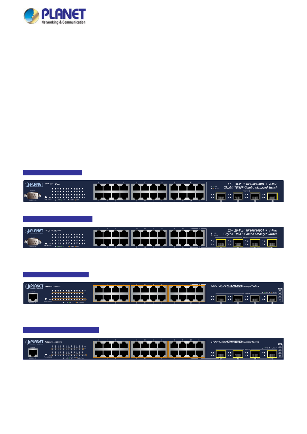
User’s Manual of WGSW Series Managed Switch
30
2. INSTALLATION
This section describes the hardware features and installation of the Managed Switch on the desktop or rack mount. For easier
management and control of the Managed Switch, familiarize yourself with its display indicators, and ports. Front panel
illustrations in this chapter display the unit LED indicators. Before connecting any network device to the Managed Switch,
please read this chapter completely.
2.1 Hardware Description
2.1.1 Switch Front Panel
The front panel provides a simple interface monitoring the Managed Switch. Figures 2-1-1 to 2-1-5 show the front panels of the
Managed Switches.
WGSW-24040 Front Panel
WGSW-24040R Front Panel
WGSW-24040HP Front Panel
Figure 2-1-1: Front Panel of WGSW-24040
Figure 2-1-2: Front Panel of WGSW-24040R
Figure 2-1-3: Front Panel of WGSW-24040HP
WGSW-24040HP4 Front Panel
Figure 2-1-4: Front Panel of WGSW-24040HP
Page 31
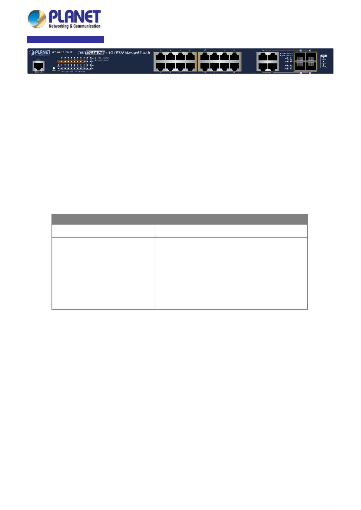
User’s Manual of WGSW Series Managed Switch
31
192.168.0.254
WGSW-20160HP Front Panel
Figure 2-1-5: Front Panel of WGSW-20160HP
■ Gigabit TP interface
10/100/1000BASE-T copper, RJ45 twisted-pair: Up to 100 meters.
■ SFP ports
100/1000BASE-X mini-GBIC port, SFP (Small Factor Pluggable) transceiver module: From 550 meters (Multi-mode fiber),
up to 10/20/40/60/80/120 kilometers (Single-mode fiber).
■ Reset button
On the left of the front panel, the reset button is designed to reboot the Managed Switch without turning off and on the
power. The following is the summary table of the reset button functions:
Reset Button Pressed and Released Function
< 5 sec: System reboot Reboot the Managed Switch
Reset the Managed Switch to Factory Default configuration.
The Managed Switch will then reboot and load the default
settings as shown below:
> 5 sec: Factory Default
。 Default Username: admin
。 Default Password: admin
。 Default IP address: 192.168.0.100
。 Subnet mask: 255.255.255.0
。 Default Gateway:
Page 32

User’s Manual of WGSW Series Managed Switch
32
■
■
■
2.1.2 LED Indications
The front panel LEDs indicate instant status of power and system status, fan status, port links / PoE-in-use and data activity;
they help monitor and troubleshoot when needed. Figures 2-1-6 to 2-1-8 show the LED indications of the Managed Switches.
WGSW-24040/WGSW-24040R LED indication
Figure 2-1-6 LED Panel of WGSW-24040/WGSW-24040R
LED Definition
System
LED Color Function
PWR Green Lights to indicate that the switch has power.
Per 10/100/1000BASE-T Port
LED Color Function
1000
LNK/ACT
10/100
LNK/ACT
Per 100/1000BASE-X SFP Interfaces
LED Color Function
1000 Green
Green
Orange
Lights to indicate the port is running in 1000Mbps speed and successfully established.
Blinks to indicate that the switch is actively sending or receiving data over that port.
Lights to indicate the port is running in 10/100Mbps speed and successfully established.
Blinks to indicate that the switch is actively sending or receiving data over that port.
Lights to indicate that the port is operating at 1000Mbps.
Off to indicate the port is operating at 100Mbps or no link.
LNK/ACT Orange
Lights to indicate the port is successfully established.
Blinks to indicate that the switch is actively sending or receiving data over that port.
Page 33

33
LED
Color
Function
FAN 2
Red
Lights to indicate that FAN 2 is down.
FAN 1
Red
Lights
PoE PWR
Red
Lights
LED
Color
Function
LED
Color
Function
WGSW-24040HP/WGSW-24040HP4 LED indication
Figure 2-1-7 LED Panel of WGSW-24040HP/ WGSW-24040HP4
LED Definition
■ System/Alert
PWR Green Lights to indicate that the Switch has power.
FAN 3 Red Lights to indicate that FAN 3 is down.
User’s Manual of WGSW Series Managed Switch
to indicate that F A N 1is down.
to indicate that the PoE power is down.
■ 802.3at PoE+ 10/100/1000BASE-T interfaces (Port-1 to Port-24)
Lights: To indicate the link through that port is successfully established.
LNK/ACT Green
PoE-in-Use Orange
■ 100/1000BASE-SX/LX SFP Combo Interfaces (Port-21 to Port-24)
1000 Green
LNK/ACT Orange
Blink: To indicate that the switch is actively sending or receiving data over that port.
Lights: To indicate the port is prov idi n g PoE power.
Off: To indicate the connected device is not providing PoE power.
Lights: To indicate that the port is operating at 1000Mbps.
Off: To indicate the port is operating at 100Mbps or no link.
Lights: To indicate the port is successfully establ ished.
Blinks: To indicate that the switch is actively sending or receiving data over that port.
Page 34

34
.
To indicate that the Switch is actively sending or receiving data over that port.
WGSW-20160HP LED Indication Table
LED Definition
■ System
LED Color Function
PWR Green Lights to indicate that the Switch has power.
SYS Green Lights to indicate the system is working.
■ Alert
LED Color Function
User’s Manual of WGSW Series Managed Switch
Figure 2-1-8 LED Panel of WGSW-20160HP
FAN 1 Red Lights to indicate that FAN 1 has failed.
FAN 2 Red Lights to indicate that FAN 2 has failed.
FAN 3 Red Lights to indicate that FAN 3 has failed.
Per 10/100/1000Mbps port with PoE interfaces (Port-1 to Port-16)
LED Color Function
LNK/ACT Green
PoE-in-Use Orange
■ Per 10/100/1000BASE-T Combo Port (Port -17 to Port-20)
Lights: To indicate the link through that port is successfully established at 10/100/1000Mbps.
Blinks: To indicate that the Switch is actively sending or receiving data over that port.
Lights: To indicate the port is prov idi n g PoE power.
Off: To indicate the connected device is not a PoE powered device (PD).
LED Color Function
1000
Green
LNK/ACT
10/100
Orange
LNK/ACT
Lights: To indicate the link through that port is successfully established at 1000Mbps.
Blink: To indicate that the Switch is actively sending or receiving data over that port.
Lights: To indicate the link through that port is successfully established at 10Mbps or
100Mbps.
Blink: To indicate that the Switch is actively sending or receiving data over that port.
■ Per 100/1000Mbps SFP Combo Interface (Port -17 to Port-20)
LED Color Function
1000 LNK/ACT Green
Lights
Blink:
Lights:
100 LNK/ACT Orange
Blink: To indicate that the Switch is actively sending or receiving data over that port.
To indicate the port is successfully established at 1000Mbps.
To indicate the port is successfully established at 100Mbps.
Page 35

User’s Manual of WGSW Series Managed Switch
35
2.1.3 Switch Rear Panel
The rear panel of the Managed Switch consists of the AC/DC inlet power socket. Figures 2-1-9 to 2-1-13 show the rear pane ls of
the Managed Switches.
WGSW-24040 Rear Panel
Figure 2-1-9 Rear Panel of WGSW-24040
WGSW-24040R Rear Panel
Figure 2-1-10 Rear Panel of WGSW-24040R
WGSW-24040HP Rear Panel
WGSW-24040HP4 Rear Panel
WGSW-20160HP Rear Panel
Figure 2-1-11 Rear Panel of WGSW-24040HP
Figure 2-1-12 Rear Panel of WGSW-24040HP4
Figure 2-1-13 Rear Panel of WGSW-20160HP
■ AC Power Receptacle
For compatibility with electrical voltages in most areas of the world, the Managed Switch’s power supply can automatically
adjust line power in the range of 100-240V AC and 50/60 Hz.
Plug the female end of the power cord fir mly into the receptacle on th e rear panel of the Managed Switch and the other end
of the power cord into an electrical outlet and the power will be ready.
Page 36

User’s Manual of WGSW Series Managed Switch
36
active all the time, please consider using UPS (Uninterrupted Power Supply) for your device.
Switch from being damaged by unregulated
The device is a power-required device, which means it will not work till it is powered. If your networks
should be
Power Notice:
It will prevent you from network data loss or network downtime. In some area s, install ing a surge
suppression device may also help to protect your Managed
surge or current to the Switch or the power adapter.
Page 37

User’s Manual of WGSW Series Managed Switch
37
Chapter 1,
45 tips. For more
2.2 Installing the Switch
This section describes how to install your Managed Switch and make connections to the Managed Switch. Please read the
following topics and perform the procedures in th e ord er being presented. To install your Managed Switch on a desktop or shel f,
simply complete the following steps.
2.2.1 Desktop Installation
To install the Managed Switch on desktop or shelf, please follow these steps:
Step 1: Attach the rubber feet to the recessed areas on the bottom of the Managed Switch.
Step 2: Place the Managed Switch on the desktop or the shelf near an AC power source, as shown in Figure 2-2-1.
Figure 2-2-1: Place the Managed Switch on the Desktop
Step 3: Keep enough ventilation space between the Managed Switch and the surrounding objects.
When choosing a location, please keep in mind the environmental restrictions discussed in
Section 4, and specifications.
Step 4: Connect the Managed Switch to network devices.
Connect one end of a standard network cable to the 10/100/1000 RJ45 ports on the front of the Managed Switch.
Connect the other end of the cable to the network devices such as printer server, workstation or router.
Connection to the Managed S w itch require s UTP C ategory 5 e network cabling with RJ
information, please see the Cabling Specification in Appendix A.
Step 5: Supply power to the Managed Switch.
Connect one end of the power cable to the Managed Switch.
Connect the power plug of the power cable to a standard wall outlet.
When the Managed Switch receives power, the Power LED should remain solid Green.
Page 38

User’s Manual of WGSW Series Managed Switch
38
e caused to the parts by
2.2.2 Rack Mounting
To install the Managed Switch in a 19-inch standard rack, please follow the instructions described below.
Step 1: Place the Managed Switch on a hard flat surface, with the front panel positioned towards the front side.
Step 2: Attach the rack-mount bracket to each side of the Managed Switch with supplied screws attached to the package.
Figure 2-2-2 shows how to attach brackets to one side of the Managed Switch.
Figure 2-2-2: Attach Brackets to the Managed Switch.
You must use the screws supplied with the mounting brackets. Damag
using incorrect screws would invalidate the warranty.
Step 3: Secure the brackets tightly.
Step 4: Follow the same steps to attach the second bracket to the opposite side.
Step 5: After the brackets are attached to the Managed Switch, use suitable screws to securely attach the brackets to the rack,
as shown in Figure 2-2-3.
Figure 2-2-3: Mounting Managed Switch in a Rack
Step 6: Proceed with Steps 4 and 5 of session 2.2.1 Desktop Installation to connect the network cabling and supply power to
the Managed Switch.
Page 39

User’s Manual of WGSW Series Managed Switch
39
2.2.3 Installing the SFP/SFP+ Transceiver
The sections describe how to insert an SFP/SFP+ transceiver into an SFP/SFP+ slot. The SFP/SFP+ transceivers are
hot-pluggable and hot-sw appa ble. You can plug in and out the transceiver to/from any SFP/SFP+ port without having to power
down the Managed Switch, as the Figure 2-2-4 shows.
Figure 2-2-4: Plug-in the SFP/SFP+ Transceiver
Approved PLANET SFP/SFP+ Transceivers
PLANET Managed Switch supports both singl e mode and multi-mode SFP/SFP+ transceivers. The following list of approved
PLANET SFP/SFP+ transceivers is correct at the time of publication:
Fast Ethernet Transceiver (100BASE-X SFP)
Model Speed (Mbps) Connector Interface Fiber Mode Distance Wavelength (nm) Operating Temp.
MFB-FX 100 LC Multi Mode 2km 1310nm 0 ~ 60 degrees C
MFB-F20 100 LC Single Mode 20km 1310nm 0 ~ 60 degrees C
MFB-F40 100 LC Single Mode 40km 1310nm 0 ~ 60 degrees C
MFB-F60 100 LC Single Mode 60km 1310nm 0 ~ 60 degrees C
MFB-F120 100 LC Single Mode 120km 1550nm 0 ~ 60 degrees C
MFB-TFX 100 LC Multi Mode 2km 1310nm -40 ~ 75 degrees C
MFB-TF20 100 LC Single Mode 20km 1550nm -40 ~ 75 degrees C
Fast Ethernet Transceiver (100BASE-BX, Single Fiber Bi-directional SFP)
Model Speed (Mbps) Connector Interface Fiber Mode Distance Wavelength (TX/RX) Operating Temp.
MFB-FA20 100 WDM(LC) Single Mode 20km 1310nm/1550nm 0 ~ 60 degrees C
MFB-FB20 100 WDM(LC) Single Mode 20km 1550nm/1310nm 0 ~ 60 degrees C
MFB-TFA20 100 WDM(LC) Single Mode 20km 1310nm/1550nm -40 ~ 75 degrees C
MFB-TFB20 100 WDM(LC) Single Mode 20km 1550nm/1310nm -40 ~ 75 degrees C
MFB-TFA40 100 WDM(LC) Single Mode 40km 1310nm/1550nm -40 ~ 75 degrees C
MFB-TFB40 100 WDM(LC) Single Mode 40km 1550nm/1310nm -40 ~ 75 degrees C
Page 40

40
L120(V2)
Connector
TLB10(V2)
Gigabit Ethernet Transceiver (1000BASE-X SFP)
User’s Manual of WGSW Series Managed Switch
Model DDM Speed (Mbps)
MGB-GT -- 1000 Copper -- 100m --
MGB-SX(V2) YES 1000 LC Multi Mode 550m 850nm
MGB-SX2(V2) YES 1000 LC Multi Mode 2km 1310nm
MGB-LX(V2) YES 1000 LC Single Mode 20km 1310nm
MGB-L40 YES 1000 LC Single Mode 40km 1310nm
MGB-L80 YES 1000 LC Single Mode 80km 1550nm
MGB-
MGB-TSX YES 1000 LC Multi Mo d e 550m 850nm
MGB-TSX2 YES 1000 LC Multi Mode 2km 1310nm
MGB-TLX(V2)
MGB-TL40 YES 1000 LC Single Mode 40km 1310nm
MGB-TL80 YES 1000 LC Single Mode 80km 1550nm
YES 1000 LC Single Mode 120km 1550nm
YES 1000 LC Single Mode 20km 1310nm
Connector
Interface
Fiber Mode Distance Wavelength (nm)
Gigabit Ethernet Transceiver (1000BASE-BX, Single Fiber Bi-directional SFP)
Operating
Temp.
0 ~ 60 ℃
0 ~ 60 ℃
0 ~ 60 ℃
0 ~ 60 ℃
0 ~ 60 ℃
0 ~ 60 ℃
0 ~ 60 ℃
-40 ~ 75 ℃
-40 ~ 75 ℃
-40 ~ 75 ℃
-40 ~ 75 ℃
-40 ~ 75 ℃
Model DDM
MGB-LA10(V2)
MGB-LB10(V2)
MGB-LA20(V2)
MGB-LB20(V2)
MGB-LA40(V2)
MGB-LB40(V2)
MGB-LA80
MGB-LB80
MGB-TLA10(V2)
MGB-
MGB-TLA20
MGB-TLB20
MGB-TLA40
MGB-TLB40
YES
YES
YES
YES
YES
YES
YES
Speed
(Mbps)
1000 WDM(LC) Single Mode 10km 1310nm 1550nm
1000 WDM(LC) Single Mode 10km 1550nm 1310nm
1000 WDM(LC) Single Mode 20km 1310nm 1550nm
1000 WDM(LC) Single Mode 20km 1550nm 1310nm
1000 WDM(LC) Single Mode 40km 1310nm 1550nm
1000 WDM(LC) Single Mode 40km 1550nm 1310nm
1000 WDM(LC) Single Mode 80km 1490nm 1550nm
1000 WDM(LC) Single Mode 80km 1550nm 1490nm
1000 WDM(LC) Single Mode 10km 1310nm 1550nm
1000 WDM(LC) Single Mode 10km 1550nm 1310nm
1000 WDM(LC) Single Mode 20km 1310nm 1550nm
1000 WDM(LC) Single Mode 20km 1550nm 1310nm
1000 WDM(LC) Single Mode 40km 1310nm 1550nm
1000 WDM(LC) Single Mode 40km 1550nm 1310nm
Interface
Fiber Mode Distance Wavelength (TX) Wavelength (RX)
Operating
Temp.
0 ~ 60 ℃
0 ~ 60 ℃
0 ~ 60 ℃
0 ~ 60 ℃
0 ~ 60 ℃
0 ~ 60 ℃
0 ~ 60 ℃
0 ~ 60 ℃
-40 ~ 75 ℃
-40 ~ 75 ℃
-40 ~ 75 ℃
-40 ~ 75 ℃
-40 ~ 75 ℃
-40 ~ 75 ℃
MGB-TLA80
YES
MGB-TLB80
1000 WDM(LC) Single Mode 80km 1490nm 1550nm
1000 WDM(LC) Single Mode 80km 1550nm 1490nm
It is recommended to use PLANET SFP/SFP+ on t he Managed Switch. If you insert an SFP/SFP+
transceiver that is not supported, the Managed Switch will not recognize it.
Before connecting the other Managed Switches, workstation or Media Converter.
-40 ~ 75 ℃
-40 ~ 75 ℃
Page 41

User’s Manual of WGSW Series Managed Switch
41
1. Make sure both sides of th e SFP transce iver ar e with t he same media type, for ex ample, 1000BASE-SX to 1000BASE-SX,
1000BASE-LX to 1000BASE-LX.
2. Check whether the fiber-opt ic cabl e type mat ches the SFP transceiver model.
To connect to 1000BASE-SX SFP transceiver, use the multi-mode fiber cable -- with one side being male duplex LC
connector type.
To connect to 1000BASE-LX SFP transceiver, use the single-mode fiber cable -- with one side being male duplex LC
connector type.
Connecting the fiber cable
1. Attach the duplex LC connector on the network cable to the SFP transceiver.
2. Connect the other end of the cable to a device – switches with SFP installed, fiber NIC on a workstation or a media
converter.
3. Check the LNK/ACT LED of the SFP port on the front of the Managed Switch. Ensure that the SFP transceiver is
operating correctly.
4. Check the Link mode of the SFP port if the link fails. It works with some fiber-NICs or media converters and sets the link
mode to “1000 Force” or “100 Force” when needed.
Removing the transceiver module
1. Make sure there is no network activity by checking with the network administrator. Or through the management interface
of the switch/converter (if available), disable the port in advance.
2. Remove the fiber optic cable gently.
3. Turn the lever of the MGB module to a horizontal position.
4. Pull out the module gently through the lever.
Figure 2-2-5 Pull out the SFP transceiver
Never pull out the module without mak ing use of the lever or the push bolts on the module.
Removing the module with forced could damage the module and SFP module port of the
Managed Switch.
Page 42

User’s Manual of WGSW Series Managed Switch
42
3. SWITCH MANAGEMENT
This chapter explains the methods that you can use to configure management access to the Managed Switch. It describes the
types of management applications and the communication and management protocols that deliver data between your
management device (workstation or personal computer) and the system. It also contains information about port connection
options.
This chapter covers the following topics:
Requirements
Management Access Overview
Administration Console Access
Web Management Access
SNMP Access
Standards, Protocols, and Related Reading
3.1 Requirements
Workstations running Windows XP/2003/2008/2012/Vista/7/8/10, MAC OS X or later, Linux, UNIX, or other
platforms are compatible with TCP/IP protocols.
Workstations are installed with Ethernet NIC (Network Interface Card)
Serial Port Connection (Terminal)
The above Workstations come with COM Port (DB9) or USB-to-RS232 converter.
The above Workstations have been installed with terminal emulator, such as Tera Term, PuTTY or Hyper
Terminal included in Windows XP/2003.
Serial cable -- one end is attached to the RS232 serial port, while the other end to the console port of the
Managed Switch.
Ethernet Port Connection
Network cables -- Use standard network (UTP) cables with RJ45 connectors.
The above PC is installed with Web browser.
It is recommended to use Internet Explorer 8.0 or above to access the Managed Switch. If the
Web interface of the Managed Switch is not accessible, please turn off the anti-virus software or
firewall and then try it again.
Page 43

User’s Manual of WGSW Series Managed Switch
43
3.2 Management Access Overview
The Managed Switch gives you the flexibility to access and manage it using any or all of the following methods:
An administration console
Web browser interface
An external SNMP-based network management application
The administration console and Web browser interface support are embedded in the Managed Switch software and are
available for immediate use. Each of these management methods has their own advantages. Table 3-1 compares the three
management methods.
Method Advantages Disadvantages
Console
Web Browser
SNMP Agent
• No IP address or subnet needed
• Text-based
• Telnet functionality and HyperTerminal
built into Windows
95/98/NT/2000/ME/XP operating
systems
• Secure
• Ideal for configuring the switch remotely
• Compatible with all popular browsers
• Can be accessed from any location
• Most visually appealing
• Communicates with switch functions at
the MIB level
• Based on open standards
• Must be near the switch or use dial-up
connection
• Not convenient for remote users
• Modem connection may prove to be unreliable
or slow
• Security can be compromised (hackers need
only know the IP address and subnet mask)
• May encounter lag times on poor connections
• Requires SNMP manager software
• Least visually appealing of all three methods
• Some settings require calculations
• Security can be compromised (hackers need
only know the community name)
Table 3-1 Comparison of Management Methods
Page 44

User’s Manual of WGSW Series Managed Switch
44
3.3 Administration Console
The administration console is an interna l, chara cter -oriented, and command line user interface for performing system
administration such as displaying statistics or changing option settings. Using this method, you can view the administration
console from a terminal, personal computer, Apple Macintosh, or workstation connected to the Managed Switch's console
(serial) port.
Figure 3-1-1: Console Management
Direct Access
Direct access to the administration console is achieved by directly connecting a terminal or a PC equipped with a
terminal-emulation program (such as HyperTerminal) to the Managed Switch console (serial) port. When us ing this
management method, a straight DB9 RS232 cable is required to connect the switch to the PC. After making this connection,
configure the terminal-emulation program to use the following parameters:
The default parameters are:
115200 bps
8 data bits
No parity
1 stop bit
Figure 3-1-2: Terminal Parameter Settings
Page 45

User’s Manual of WGSW Series Managed Switch
45
You can change these settings, if desired, after you log on. This management method is often preferred because you can
remain connected and monitor the system during system reboots. Also, certain error messages are sent to the serial port,
regardless of the interface through which the associated action was initiated. A Macintosh or PC attachment can use any
terminal-emulation program for connecting to the terminal serial port. A workstation attachment under UNIX can use an
emulator such as TIP.
3.4 Web Management
The Managed Switch offers management features that allow users to manage the Managed Switch from anywhere on the
network through a stan dard brow ser suc h as M icrosof t Inter net Ex plorer. Af ter y ou set up yo ur IP address for the sw itch, yo u can
access the Managed Switch's Web interface applications directly in your Web browser by entering the IP address of the
Managed Switch.
Figure 3-1-3: Web Management
You can then use your Web browser to list and manage the M anaged Sw itch c onf iguration parameters fro m one ce ntral location,
just as if you were directly connected to the Managed Switch's console port. Web Management requires either Microsoft
Internet Explorer 8.0 or other latest Web browser tools.
Figure 3-1-4: Web Main Screen of Managed Switch
Page 46

User’s Manual of WGSW Series Managed Switch
46
different LAN card
3.5 SNMP-based Network Management
You can use an external SNMP-based application to configure and manage the Managed Switch, such as SNMP Network
Manager, HP Openview Network Node Management (NNM) or What’s Up Gold. This management method requires the SNMP
agent on the switch and the SNMP Network Management Station to use the same community string. This management
method, in fact, uses two community strings: the get community string and the set community string. If the SNMP Net-work
management Station only knows the set community string, it can read and write to the MIBs. However, if it only knows the get
community string, it can only read MIBs. The default getting and setting community strings for the Managed Switch is public.
Figure 3-1-5: SNMP Management
3.6 PLANET Smart Discovery Utility
For easily listing the Managed Switch in your Ethernet environment, the Planet Smart Discovery Utility from user’s manual
CD-ROM is an ideal solution. The following install ation instructions are to guide you to running the Planet Smart Discovery
Utility.
1. Deposit the Planet Smart Discovery Utility in administrator PC.
2. Run this utility as the following screen appears.
If there are two LAN cards or above in the same administrator PC, choose a
by using the “Select Adapter” tool.
Figure 3-1-6: Planet Smart Discovery Utility Screen
Page 47

User’s Manual of WGSW Series Managed Switch
47
4. Press the “Refresh” button for the currently connected devices in the discovery list as the screen shows below:
Figure 3-1-7: Planet Smart Discovery Utility Screen
1. This utility shows all necessary information from the devices, such as MAC address, device name, firmware version, and
device IP subnet address. It can also assign new password, IP subnet address and description to the devices.
2. After setup is completed, press the “Update Device”, “Update Multi” or “Update All” button to take effect. The functions of
the 3 buttons above are shown below:
Update Device: use current setting on one single device.
Update Multi: use current setting on choose multi-devices.
Update All: use current setting on whole devices in the list.
The same functions mentioned above also can be found in “Option” tools bar.
3. To click the “Control Packet Force Broadcast” function, it allows you to assign a new setting value to the Web Smart
Switch under a different IP subnet address.
4. Press the “Connect to Device” button and the Web login screen appears in Figur e 3-1-4.
5. Press the “Exit” button to shut down the Planet Smart Discovery Utility.
Page 48

User’s Manual of WGSW Series Managed Switch
48
.0 or later version does not allow Java Applets to open sockets. The user has to expli citly
4. WEB CONFIGURATION
This section introduces the configuration and functions of the Web-based management from Managed Switch.
About Web-based Management
The Managed Switch offers management features that allow users to manage the Managed Switch from anywhere on the
network through a standard browser such as Microsoft Internet Explorer.
The Web-based Management supports Inter net Explorer 7.0. It is based on Java Applets with an aim to reduce network
bandwidth consumption, enhance ac cess spee d and presen t an easy viewing screen.
By default, IE7
modify the browser setting to enable Java Applets to use network ports.
The Managed Switch can be configured through an Ether net connect ion, making sure the manager PC must be set to the same
IP subnet address with the Managed Switch.
For example, the default IP address of the Managed Switch is 192.168.0.100, then the manager PC should be set to
192.168.0.x (where x is a number between 1 and 254, except 100), and the default subnet mask is 255.255.255.0.
If you have changed the def au l t IP address of the Managed Switch to 192.16 8.1.1 with subnet mask 255. 255. 255.0 via console,
then the manager PC should be set to 192.168.1.x (where x is a number between 2 and 254) to do the relative configuration on
manager PC.
Figure 4-1-1: Web Management
Logging on to the Managed Switch
1. Use Internet Explorer 8.0 or above Web browser. Enter the factory-default IP address to access the Web interface . T he
factory-default IP address is shown as follows:
http://192.168.0.100
Page 49

User’s Manual of WGSW Series Managed Switch
49
2. When the following login screen appears, please enter the default username "admin" with password “admin” (or the
username/password you have changed via console) to login the main screen of Managed Switch. The login screen in
Figure 4-1-2 appears.
Figure 4-1-2: Login Screen
Default User name: admin
Default Password: admin
After entering the username and password, the main screen appears as shown in Figure 4-1-3.
Figure 4-1-3: Web Main Page
Now, you can use the Web management interface to continue the switch management or manage the Managed Switch by Web
interface. The Switch Menu on the left of the web page lets you access all the commands and statistics the Managed Switch
provides.
Page 50

User’s Manual of WGSW Series Managed Switch
50
1. It is recommended to use Internet Explore 7.0 or above to access Managed Switch.
2. The changed IP address takes effect immediately after clicking on the Save button. You need to
use the new IP address to access the Web interface.
3. For security reason, please change and memorize the new password after this first setup.
4. Only accept command in lowercase letter under web interface.
4.1 Main Web Page
The Managed Switch provides a Web-based browser interface for configuring and managi n g it. This interface allows you to
access the Managed Switch using the Web browser of your choice. This chapter describes how to use the Managed Switch’s
Web browser interface to configure and manage it.
Main Functions
Copper Port Link
SFP/SFP+ Port Link
Help Button
Figure 4-1-4: Web Main Page
Main Screen
Panel Display
The web agent displays an image of the Managed Switch’s ports. The M ode can be set to display dif ferent information for the
ports, including Link up or Link down. Clicking on the image of a port opens the Port Statistics page.
The port status are illustrated as follows:
State Disabled Down Link
RJ45 Ports
SFP Ports
Main Menu
Using the onboard web age nt, you can define system parameters, manage and contr ol the Managed Switch, and al l it s po rt s, o r
monitor network conditions. Via the Web-Management, the administrator can set up the Managed Switch by selecting the
functions those listed in the Main Function. The screen in Figure 4-1-5 appears.
Page 51

User’s Manual of WGSW Series Managed Switch
51
Figure 4-1-5: Managed Switch Main Functions Menu
Page 52

User’s Manual of WGSW Series Managed Switch
52
on
P protocol layer. The status is defined
by the IP interfaces, the IP routes and the neighbor cache (ARP cache)
4.2 System
Use the System menu items to display and configure basic administra tive det ail s of the M anaged Switch. Under the System, the
following topics are provided to configure and view the system information. This section has the following items:
■ System Information The Managed Switch system information is provided here.
■ IP Configuration Configure the IP
this page.
■ IP Status
■ ARP Configuration
■ Users Configuration
■ Privilege Levels
■ NTP Configuration Configure NTP server on this page.
■ Time Configuration Configure time parameter on this page.
■ UPnP Configure UPnP on this page.
■ DHCP Relay Configure DHCP Relay on this page.
■ DHCP Relay Statistics This page provides statistics for DHCP relay.
■ CPU Load This page displays the CPU load, using an SVG graph.
■ System Log The system log information of the Managed Switch system is provided here.
This page displays the status of the I
status.
This page provide ARP configuration on this page.
This page provides an overview of the current users. Currently the only way
to login as another user on the web server is to close and reopen the
browser.
This page provides an overview of the privilege levels.
v4/IPv6 interface and IP routes of the Managed Switch
■ Detailed Log
■ Remote Syslog Configure remote syslog on thi s page.
■ SMTP Configuration Configure SMTP parameters on this page.
■ SNMP Configure SNMP parameters on this page
■ RMON Configure the RMON parameters on this page
■ DHCP server
■ Remote Management
The detailed log information of the Managed Switch system is provided here .
Configure the DHCP server on this page
Configure the Remote Management on this page
Page 53
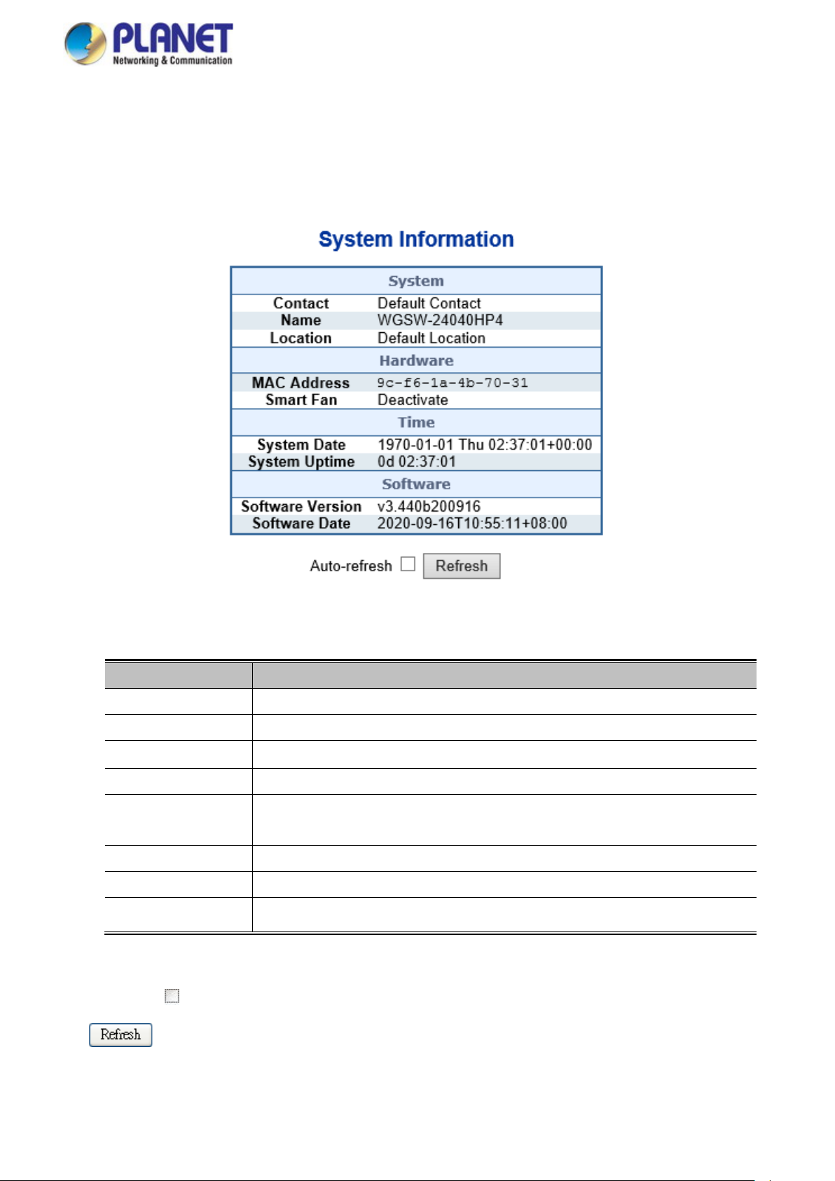
User’s Manual of WGSW Series Managed Switch
53
4.2.1 Management
4.2.1.1 System Information
The System Infomation page provides information for the curr ent devi ce information. System Information page helps a switch
administrator to identify the hardware MAC address, software version and system upt ime. The screen in Figure 4-2-1 appears.
The page includes the following fields:
Object Description
• Contact
• Name
• Location
• MAC Address
• System Date
• System Uptime
• Software Version
• Software Date
Buttons
The system contact configured in SNMP | System Information | System Contact.
The system name configured in SNMP | System Information | System Name.
The system location configured in SNMP | System Information | System Location.
The MAC Address of this Managed Switch.
The current (GMT) system time and date. The system time is obtained through the
configured NTP Server, if any.
The period of time the device has been operational.
The software version of the Managed Switch.
The date when the M anaged Switch software was produced.
Figure 4-2-1: System Information Page Screenshot
Auto-refresh : Check this box to refresh the page automatically. Automatic refresh occurs every 3 seconds.
: Click to refresh the page; any changes made locally will be undone.
Page 54

User’s Manual of WGSW Series Managed Switch
54
4.2.1.2 IP Configuration
The IP Configuration includes the IP Configuration, IP Interface and IP Routes. The configured column is used to view or
change the IP configuration. The maximum number of interfaces supported is 128 and the maximum number of routes is 32.
The screen in Figure 4-2-2 appears.
Figure 4-2-2: IP Configuration Page Screenshot
The current column is used to show the active IP configuration.
Object Description
• IP Configurations Domain Name
Mode
DNS Server
Configure the Switch Domain Name
Configure whether the IP stack should act as a Host or a Router. In
Host mode, IP traffic between interfaces will not be routed. In Router
mode traffic is routed between all interfaces.
This setting controls the DNS name resolution done by the switch. The
following modes are supported:
No DNS server
No DNS server will be used..
Configure IPv4 or IPv6
Explicitly specify the name of local domain.
Make sure the configured domain name meets your organization's
given domain.
From any DHCPv6 interfaces
The first domain name offered from a DHCPv6 lease to a
DHCPv6-enabled interface will be used.
From this DHCPv6 interface
Specify from which DHCPv6-enabled interface a provided domain
name should be preferred..
DNS Proxy
When DNS proxy is enabled, system will relay DNS requests to the
currently configured DNS server, and reply as a DNS resolver to the
Page 55

User’s Manual of WGSW Series Managed Switch
55
The destination IP network or host address of this route. Valid format is
client devices on the network.
• IP Interface Delete
VLAN
IPv4
DHCP
IPv4 Address
DHCPv6 Enable
Enabled
Fallback
Current
Lease
Mask Length
Rapid
Commit
Select this option to delete an existing IP interface.
The VLAN associated with the IP interface. Only ports in this VLAN will
be able to access the IP interface. This field is only available for input
when creating a new interface.
Enable the DHCP client by checking this box.
The number of seconds for trying to obtain a DHCP lease.
For DHCP interfaces with an active lease, this column shows the
current interface address, as provided by the DHCP server.
Provide the IP address of this Managed Switch in dotted decimal
notation.
The IPv4 network mask, in number of bits (prefix length). Valid values
are between 0 and 30 bits for a IPv4 address.
Enable the DHCPv6 clien t by c hecking this box . If thi s opt ion i s enable d,
the system will configure the IPv6 address of the interface using the
DHCPv6 protocol
Enable the DHCPv6 Rapid-Commit option by checking this box. If this
option is enabled, the DHCPv6 client terminates the waiting process as
IPv6 Address
• IP Routes Delete
Network
Mask Length
Gateway
Current
Lease
Mask Length
soon as a Reply message with a Rapid Commit option is received.
This option is only manageable when DHCPv6 client is enabled.
For DHCPv6 interface with an active lease, this column shows the
interface address provided by the DHCPv6 server
Provide the IP address of this Managed Switch. An IPv6 address is in
128-bit records represented as eight fields of up to four hexadecimal
digits with a colon separating each field (:).
The IPv6 network mask, in number of bits (prefix length). Valid values
are between 1 and 128 bits for an IPv6 address.
Select this option to delete an existing IP route.
dotted decimal notation or a valid IPv6 notation. A default route can use
the value 0.0.0.0 or IPv6 :: notation.
The destination IP network or host mask, in number of bits (prefix
length).
The IP address of the IP gateway. Valid format is dotted decimal
notation or a valid IPv6 notation. Gateway and Network must be of the
same type.
Next Hop VLAN
Buttons
The VLAN ID (VID) of the specific IPv6 interface associated with the
gateway.
Page 56

User’s Manual of WGSW Series Managed Switch
56
: Click to add a new IP interface. A maximum of 128 interfaces are supported.
: Click to add a new IP route. A maximum of 32 routes are supported.
: Click to apply changes.
: Click to undo any changes made locally and revert to previously saved values.
4.2.1.3 IP Status
IP Status displays the status of the IP protocol layer. The status is defined by the IP interfaces, the IP routes and the neighbor
cache (ARP cache) status. T he screen in Figure 4-2-3 appears.
Figure 4-2-3: IP Status Page Screenshot
The page includes the following fields:
Object Description
• IP Interfaces
• IP Routes
Interface The name of the interface.
Type
Address The current address of the interface (of the given type).
Status The status flags of the interface (and/or address).
Network The destination IP network or host address of this route.
Gateway The gateway address of this route.
The address type of the entry. This may be LINK or IPv4.
Page 57

User’s Manual of WGSW Series Managed Switch
57
Status The status flags of the route.
• Neighbor Cache
Buttons
Auto-refresh : Check this box to refresh the page automatically. Automatic refr es h occur s ever y 3 seconds.
: Click to refresh the page.
IP Address The IP address of the entry.
Link Address The Link (MAC) addr es s f or w hich a binding to the IP address given exists.
4.2.1.4 ARP Configuration
This page provides ARP configuration sett ing s. press the “Apply” button to take effect, the screen in Figure 4-2-4 appears.
Figure 4-2-4: ARP Configuration Page Screenshot
The page includes the following fields:
Object Description
• Aging
Configuration
• ARP Table
Buttons
: Click to refresh the page.
: Clears all statist ics.
Disable Automatic Aging Allow to click to disable the automatic aging.
Allow to change the aging t ime settings and the available ran ge is 10 t o
Aning Time
1000000 seconds.
IP Address Display the IP address.
Link Address Display the VLAN and MAC address information.
Page 58
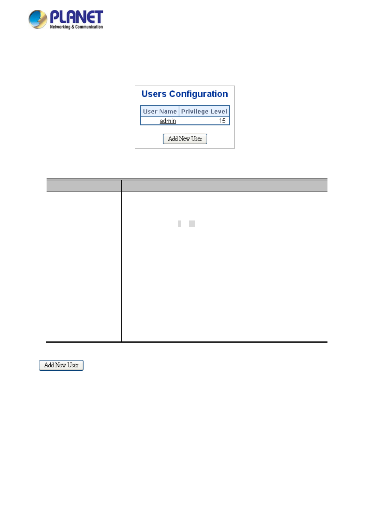
User’s Manual of WGSW Series Managed Switch
58
4.2.1.5 Users Configuration
This page provides an overview of the current users. Currently the only way to login as another user on the web server is to
close and reopen the br owser. After setup is completed, press the “Apply” button to take effect. Please login web interface w ith
new user name and password; the screen in Fi gur e 4-2-5 appears.
Figure 4-2-5: Users Configuration Page Screenshot
The page includes the following fields:
Object Description
Buttons
• User Name
• Privilege Level
: Click to add a new user.
The name identifying the user. This is also a link to Add/Edit User.
The privilege level of the user.
The allowed range is 1 to 15. If the privilege level value is 15, it can access all
groups, i.e. that is granted the full control of the device. But other values need to
refer to each group privileg e le v el. User 's priv i lege should be the same or greater
than the group privilege level to have the access to that group.
By default setting, most groups privilege level 5 has the read-only acce ss and
privilege level 10 has the read-write access. And the system maintenance
(software upload, factory defaults and etc.) needs user privilege level 15.
Generally, the privilege level 15 can be used for an administrator account,
privilege level 10 for a standard user account and privilege level 5 for a guest
account.
Page 59

59
Add/Edit User
This page configures a user – add, edit or delete user.
Figure 4-2-6: Add / Edit User Configuration Page Screenshot
The page includes the following fields:
Object Description
User’s Manual of WGSW Series Managed Switch
• Username
• Password
• Password (again)
• Privilege Level
A string identifying the user name that this entry should belong to. The allowed
string length is 1 to 31. The valid user name is a combination of letters, numbers
and underscores.
The password of the user. The allowed string length is 1 to 31.
Please enter the user’s new password here again to confirm.
The privilege level of the user.
The allowed range is 1 to 15. If the privilege level value is 15, it can access all
groups, i.e. that i s grant ed the fully control of t he dev ic e. But others value need t o
refer to each group privilege level. User's privilege sho uld be same or great er
than the group privilege level to have the access of that group.
By default setting, most groups privilege level 5 has the read-only acce ss and
privilege level 10 has the read-write access. And the system maintenance
(software upload, factory defaults and etc.) needs user privilege level 15.
Generally, the privilege level 15 can be used for an administrator account,
privilege level 10 for a standard user account and privilege level 5 for a guest
Buttons
account.
: Click to apply changes.
: Click to undo any changes made locally and revert to previously saved values.
: Click to undo any changes made locally and return to the Users.
: Delete the current user. This button is not available for new configurations (Add new user).
Page 60
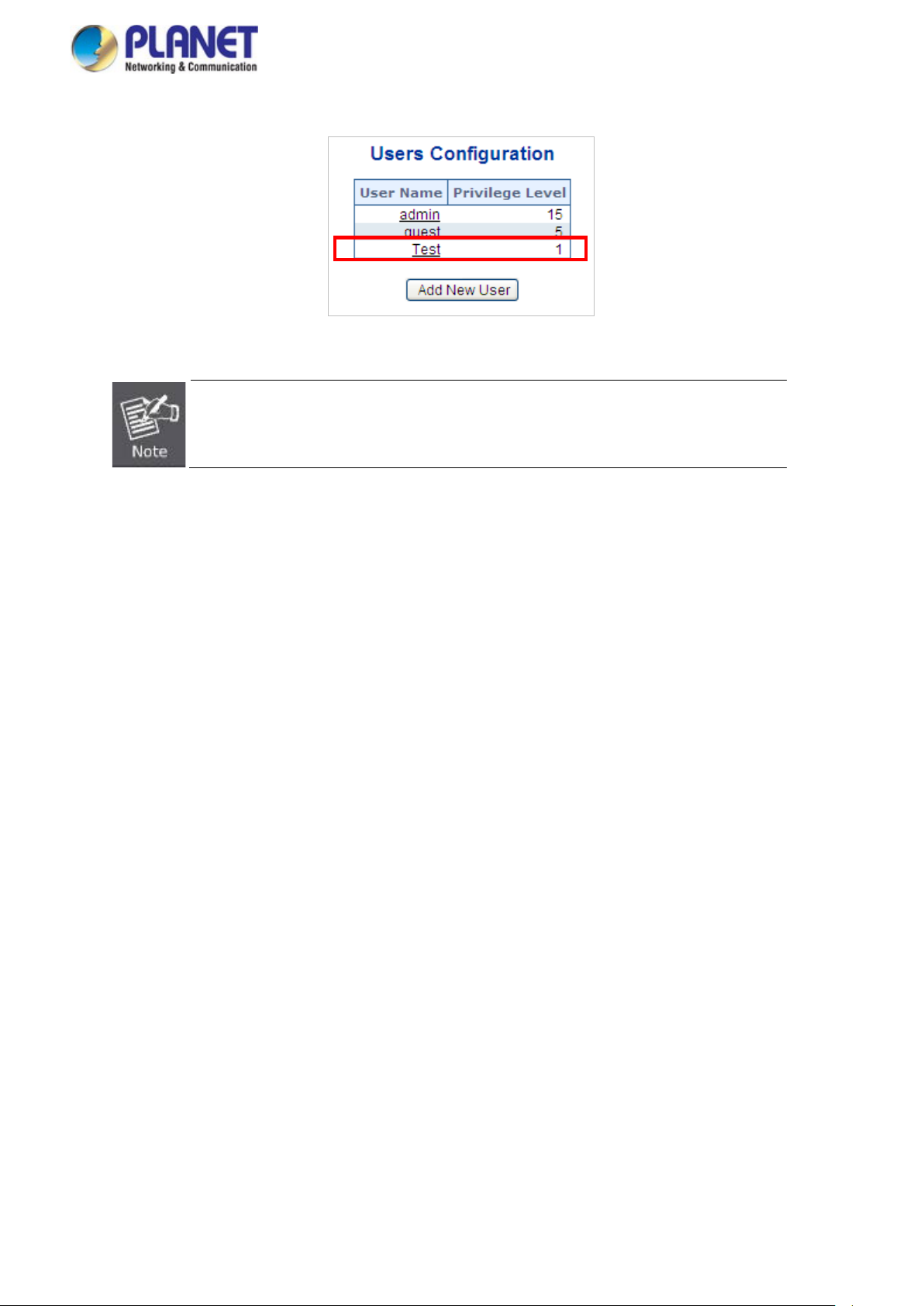
User’s Manual of WGSW Series Managed Switch
60
he
will restore to the default
Once the new user is added, the new user entry is shown on the Users Configuration page.
Figure 4-2-7: User Configuration Page Screenshot
If you forget the new password after changing the default password, please press the “Reset”
button on the front panel of the Managed Switch for over 10 seconds and then release it. T
current setting including VLAN will be lost and the Managed Switch
mode.
Page 61

User’s Manual of WGSW Series Managed Switch
61
4.2.1.6 Privilege Levels
This page provides an overview of the privilege levels. Afte r setup is completed, please press the “Apply” button to take effect.
Please login web interface with new user name and password and the screen in Figure 4-2-8 appears.
Figure 4-2-8: Privilege Levels Configur ation Page Screenshot
The page includes the following fields:
Object Description
• Group Name
The name identifying the privilege group. In most cases, a privilege level group
consists of a single module (e. g. LA CP, RSTP or QoS), but a few of them contain
more than one. The following description defines these privilege level groups in
details:
System: Contact, Name, Location, Timezone, Log.
Security: Authentication, System Acce ss Management, Port (cont ains Dot1x
Page 62
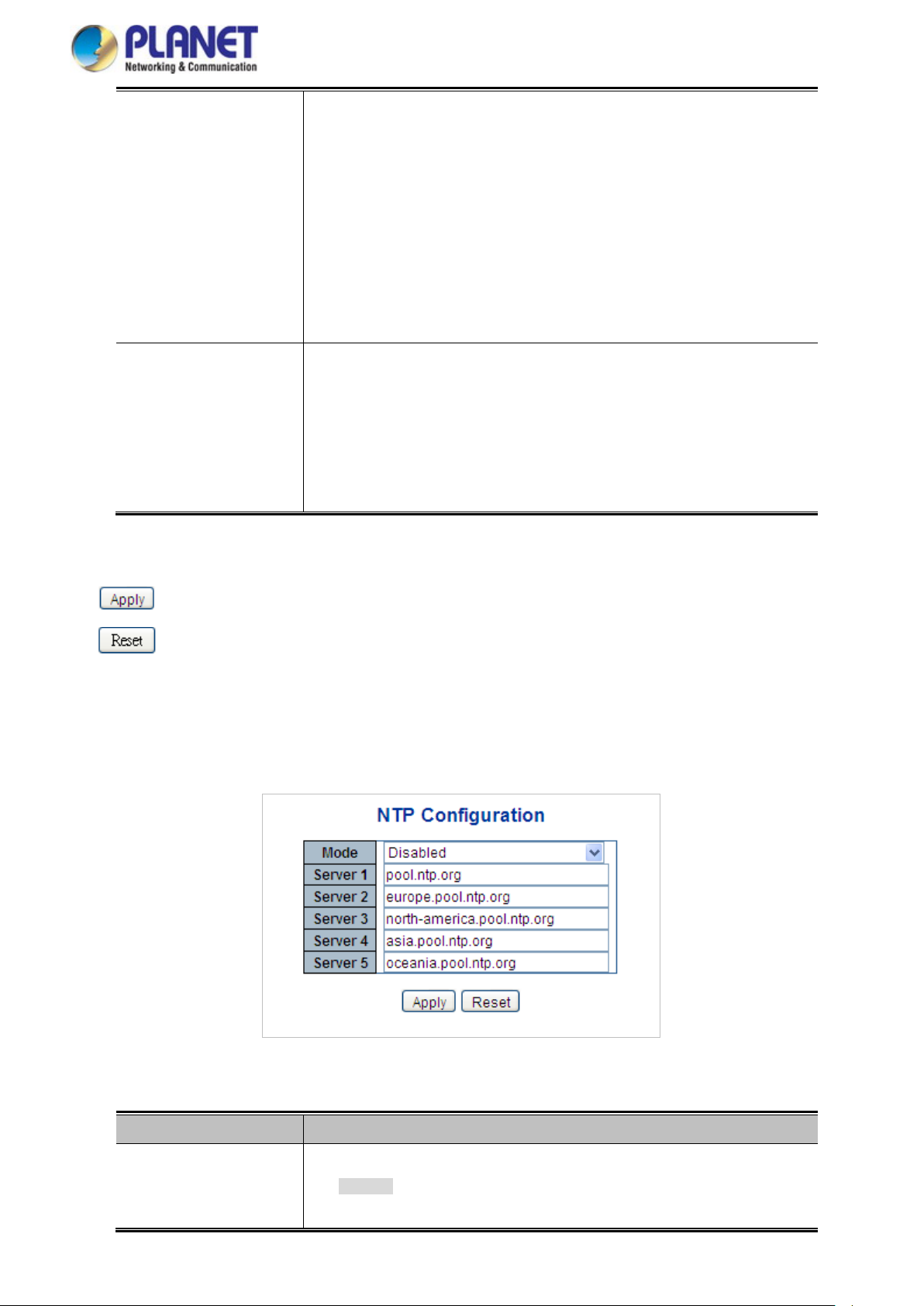
User’s Manual of WGSW Series Managed Switch
62
port, MAC based and the MAC Address Limit), ACL, HTTPS, SSH, ARP
Inspection and IP source guard.
IP: Everything except 'ping'.
Port: Everything except 'VeriPHY'.
Diagnostics: 'ping' and 'VeriPHY'.
Maintenance: CLI- System Reboot, System Restore Default, System
Password, Configuration Save, Configuration Load and Firmware Load.
Web- Users, Privilege Levels and everything in Maintenance.
Debug: Only present in CLI.
• Privilege Level
Every privilege level group has an authorization level for the following sub
groups:
Configuration read-only
Configuration/execute read-write
Status/statistics read-only
Status/statistics read-write (e.g. for clearing of statistics).
Buttons
: Click to apply changes.
: Click to undo any changes made locally and revert to previously saved values.
4.2.1.7 NTP Configuration
Configure NTP on t h is page. NTP is an acronym for Net work Time Protocol, a network protocol for synchr oniz in g the cl oc ks o f
computer systems. NTP uses UDP (data gram s) as transport layer. You can specify NTP Servers. The NTP Configuration
screen in Figure 4-2-9 appears.
The page includes the following fields:
Object Description
• Mode
Figure 4-2-9: NTP
Indicates the NTP mode operation. Possible modes are:
Configuration Page Screenshot
Enabled: Enable NTP mode operation. When enabling NTP mode
operation, the agent forward and transfer NTP messages between the
Page 63

User’s Manual of WGSW Series Managed Switch
63
clients and the server when they are not on the same subnet domain.
Disabled: Disable NTP mode operation.
Buttons
• Server #
: Click to apply changes.
: Click to undo any changes made locally and revert to previously saved values.
Provide the NTP IPv4 or IPv6 address of this switch. IPv6 address is in 128-bit
records represented as eight fields of up to four hexadecimal digits with a colon
separating each field (:).
For example, 'fe80::215:c5ff:fe03:4dc7'. The symbol '::' is a special syntax that
can be used as a shorthand way of representing multiple 16-bit groups of
contiguous zeros, but it can only appear once. It also uses a legal IPv4 address
like '::192.1.2.34'.
Page 64

User’s Manual of WGSW Series Managed Switch
64
4.2.1.7.1 System Time Correction Manually
Configure NTP on th is page. NTP is an acronym for Network Time Protocol, a n etwork protocol for synchr oniz in g the cl oc ks o f
computer systems. NTP uses UDP (data grams) as transport layer. You can specify NTP Servers. The NTP Configuration
screen in Figure 4-2-10 appears.
Figure 4-2-10: System time correction Manually Page Screenshot
The page includes the following fields:
Object Description
• User Manually
• Date
Buttons
: Click to apply changes.
: Click to undo any changes made locally and revert to previously saved values.
Indicates the NTP mode as manual operation. Possible modes are:
Enabled: Enable NTP manual mode operation. When enabling NTP user
manually mode operation, the system time will follow the date setting.
Disabled: Disable NTP user manual mode operation.
If enable the user manually , Sw itch can set the Year / Mouth / Day/ Hour / M inute
/ Second in this page
Page 65
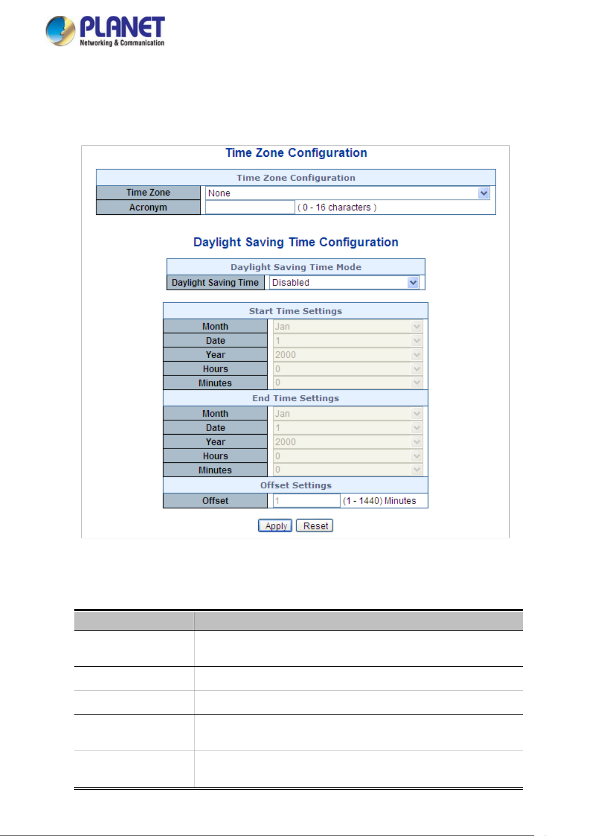
User’s Manual of WGSW Series Managed Switch
65
4.2.1.8 Time Configuration
Configure T ime Zone on this page. A Time Zone is a region that has a uniform standard time for legal, commercial, and social
purposes. It is convenient for areas in close commercial or other communication to keep the same time, so time zones tend to
follow the boundaries of countries and their subdivisions. The Time Zone Configuration screen in Figure 4-2-11 appears
The page includes the following fields:
Object Description
• Time Zone
• Hour
• Minutes
• Acronym
• Daylight Saving Time
Figure 4-2-11: Time Configuration Page Screenshot
Lists various Time Zones worldwide. Select appropriate Time Zone from the
drop-down and click Save to set.
Display the hour information.
Display the minutes information.
User can set the acronym of the time zone. This is a User configurable acronym
to identify the time zone. ( Range: Up to 16 characters )
This is used to set the clock forward or backward according to the configurations
set below for a defined Daylight Saving Time duration. Select 'Disable' to disable
Page 66

User’s Manual of WGSW Series Managed Switch
66
the Daylight Saving Time configuration. Select 'Recurring' and configure the
Daylight Saving Time duration to repeat the configuration every year. Select
'Non-Recurring' and configure the Daylight Saving Time duration for single time
configuration. ( Default: Disabled ).
• Start Time Settings • Week - Select the starting week number.
• Day - Select the starting day.
• Month - Select the starting month.
• Hours - Select the starting hour.
• Minutes - Select the starting minute.
• End Time Settings • Week - Select the ending week number.
• Day - Select the ending day.
• Month - Select the ending month.
• Hours - Select the ending hour.
• Minutes - Select the ending minute
• Offset Settings
Buttons
: Click to apply changes.
: Click to undo any changes made locally and revert to previously saved values.
Enter the number of minutes to add during Daylight Saving Time. ( Range: 1 to
1440 )
4.2.1.9 UPnP
Configure UPnP on this page. UPnP is an acronym for Universal Plug and Play. The goals of UPnP are to allow devices to
connect seamlessly and to simplify the implementation of networks in the home (data sharing, communications, and
entertainment) and in corporate environments for simplified installation of computer components. The UPnP Configuration
screen in Figure 4-2-12 appears.
Figure 4-2-12: UPnP Configuration Page Screenshot
Page 67

67
The page includes the following fields:
Object Description
User’s Manual of WGSW Series Managed Switch
• Mode
• Advertising Duration
• IP Addressing Mode
Indicates the UPnP operation mode . Pos sible mod es are:
Enabled: Enable UPnP mode operation.
Disabled: Disable UPnP mode operation.
When the mode is enabled, two ACEs are added automatically to trap UPnP
related packets to CPU. The ACEs are automatically removed when the mode is
disabled.
The duration, carried i n SS DP packets, is used to inform a control point or contr ol
points how often it or they should receive a SSDP advertisement message from
this switch. If a control point does not receive any message within the duration, it
will think that the switch no longer exists. Due to the unreliable nature of UDP, in
the standard it is recommended that such refreshing of advertisements to be
done at less than one-half of the advertising duration. In the implementation, the
switch sends SSDP messages periodically at the interval one-half of the
advertising duration minus 30 seconds. Valid values are in the range 100 to
86400.
IP addressing mode provides two ways to determine IP address assignment:
Dynamic: Default selection for UPnP. UPnP module helps users choosing the IP
• Static VLAN Interface
ID
Buttons
: Click to apply changes
: Click to undo any changes made locally and revert to previously saved values.
address of the switch device. It finds the first available system IP address.
Static: User specifies the IP interface VLAN for choosing the IP address of the
switch device.
The index of the specific IP VLAN interface. It will only be applied when IP
Addressing Mode is static. Valid configurable values ranges from 1 to 4095.
Default value is 1.
Page 68

User’s Manual of WGSW Series Managed Switch
68
4.2.1.10 DHCP Relay
Configure DHCP Relay on thi s page. DHCP Relay is used to forward and t ran sfer DHCP messages be tween the clients and th e
server when they are not on the same subnet domain.
The DHCP option 82 enables a DHCP relay agent to insert specific information into a DHCP request packets when forwarding
client DHCP packets to a DHCP server a nd re mov e the specific informati on from a DHCP reply pac ket s when forwarding server
DHCP packets to a DHCP client. The DHCP server can use this information to implement IP address or other assignment
policies. Specifically the option works by setting two sub-options:
Circuit ID (option 1)
Remote ID (option 2)
The Circuit ID sub-option is supposed to include information specific to which circuit the request came in on.
The Remote ID sub-option was designed to carry information relating to the remote host end of the circuit.
The definition of Circuit ID in the switch is 4 bytes in length and the format is "vlan_id" "module_id" "port_no". The parameter of
"vlan_id" is the first two bytes representing the VLAN ID. The param et er of "mod ule_id" is the third byte for the module ID. The
parameter of "port_no" is the fourth byte and it means the port number.
The Remote ID is 6 bytes in le ngth, and t he val ue equals the DHCP relay agent’ s M AC address. The DHCP Relay Configuration
screen in Figure 4-2-14 appears.
Figure 4-2-14 DHCP Relay Configuration Page Screenshot
The page includes the following fields:
Object Description
• Relay Mode
Indicates the DHCP relay mode operation. Possible modes are:
Enabled: Enable DHCP relay mode operation. When enabling DHCP relay
mode operation, the agent forwards and transfers DHCP me ssa ges between
the clients and the server when they are not on the same subnet domain.
And the DHCP broadcast message won't flood for security considered.
Disabled: Disable DHCP relay mode operation.
• Relay Server
• Relay Information
Mode
Indicates the DHCP relay server IP address. A DHCP relay agent is used to
forward and transfer DHCP messages between the clients and the server when
they are not on the same subnet domain.
Indicates the DHCP relay information mode option operation. Possible modes
are:
Page 69

User’s Manual of WGSW Series Managed Switch
69
contains relay age nt information. It will enf orce the policy. And it only works un der
Enabled: Enable DHCP relay information mode operation. When enabling
DHCP relay information mode operation, the agent inserts specific
information (option82) into a DHCP message when forwarding to DHCP
server and removing it from a DHCP message when transferring to DHCP
client. It only works under DHCP relay operation mode enabled.
Disabled: Disable DHCP relay information mode operation.
Buttons
• Relay Information
Policy
Indicates the DHCP relay information option policy. When enabling DHCP relay
information mode operation, if agent rec eiv es a DHCP message that already
DHCP relay information operation mode enabled. Possible policies are:
Replace: Replace the original relay information when receiving a DHCP
message that already contains it.
Keep: Keep the original relay information when receiving a DHCP message
that already contains it.
Drop: Drop the package when receiving a DHCP message that already
contains relay information.
: Click to apply changes
: Click to undo any changes made locally and revert to previously saved values.
4.2.1.11 DHCP Relay Statistics
This page provides statistics for DHCP relay. The DHCP Relay Statistics screen in Figure 4-2-15 appears.
Figure 4-2-15: DHCP Relay Statistics Page Screenshot
The page includes the following fields:
Server Statistics
Object Description
• Transmit to Server
The packets number that relayed from client to server.
Page 70

User’s Manual of WGSW Series Managed Switch
70
• Transmit Error
• Receive from Server
• Receive Missing Agent
Option
• Receive Missing
Circuit ID
• Receive Missing
Remote ID
• Receive Bad Circuit ID
Receive Bad Remote ID The packets number whose the Remote ID option did not match known Remote
Client Statistics
Object Description
• Transmit to Client
The packets number that erroneously sent packets to clients.
The packets number that received packet s fro m server.
The packets number that received packets without agent information options.
The packets number that received packets whose the Circuit ID option was
missing.
The packets number that rec ei v ed packets whose Remote ID option was
missing.
The packets number whose the Circuit ID option did not match known circuit ID.
ID.
The packets number that relayed packets from server to client.
• Transmit Error
• Receive from Client
• Receive Agent Option
• Replace Agent Option
• Keep Agent Option
• Drop Agent Option
Buttons
Auto-refresh : Check this box to refresh the page automatically. Automatic refresh occurs every 3 seconds.
: Click to refresh the page immediately.
: Clears all statist ics.
The packets number that erroneously sent packets to servers.
The packets number that received pac ket s from serv er.
The packets number that received packets with relay agent information option.
The packets number that replaced received packets with relay agent information
option.
The packets number that kept received packets with relay agent information
option.
The packets number that dropped received packets with relay agent information
option.
Page 71

User’s Manual of WGSW Series Managed Switch
71
, please download Adobe SVG tool and
4.2.1.12 CPU Load
This page displays the CPU load, using an SVG graph. The load is measured as average over the last 100ms, 1 sec and 10
seconds intervals. The last 120 samples are graphed, and the last numbers are displayed as text as well. In order to display the
SVG graph, your browser must support the SVG format. Consult the SVG Wiki for more information on browser support.
Specifically, at the time of writing, M icros oft Internet Explorer will need to have a plugi n i nstalled to support SV G . The CPU Load
screen in Figure 4-2-16 appears.
Figure 4-2-16: CPU Load Page Screenshot
Buttons
Auto-refresh : Check this box to refresh the page automatically. Automatic refresh occurs every 3 seconds.
If your browser cannot display anything on this page
install it in your computer.
Page 72

User’s Manual of WGSW Series Managed Switch
72
4.2.1.13 System Log
The Managed Switch system log informat ion is provided here. The System Log screen in Figure 4-2-17appears.
Figure 4-2-17: System Log Page Screenshot
The page includes the following fields:
Object Description
• ID
• Level
• Clear Level
• Time
• Message
The ID (>= 1) of the system log entry.
The level of the system log entry. The following level types are supported:
Info: Information level of the system log.
Warning: Warning level of the system log.
Error: Error level of the system log.
All: All levels.
To clear the system log entry level. The following level types are supported:
Info: Information level of the system log.
Warning: Warning level of the system log.
Error: Error level of the system log.
All: All levels.
The time of the system log entry.
The message of the system log entry.
Buttons
Auto-refresh : Check this box to refresh the page automatically. Automatic refresh occurs every 3 seconds.
: Updates the system log entries, starting from the current entry ID.
: Flushes the selected log entries.
: Hides the selected log entries.
: Downloads the selected log entries.
: Updates the system log entries, starting from the first available entry ID.
Page 73

User’s Manual of WGSW Series Managed Switch
73
: Updates the system log entries, ending at the last entry currently displayed.
: Updates the system log entries, starting from the last entry currently displayed.
: Updates the system log entries, ending at the last available entry ID.
4.2.1.14 Detailed Log
The Managed Switch system detailed log information is provided here. The Detailed Log screen in Figure 4-2-18 appears.
The page includes the following fields:
Object Description
• ID
• Message
Buttons
: Download the system log entry to the current entry ID.
: Updates the system log entry to the current entry ID.
: Updates the system log entry to the first available entry ID.
: Updates the system log entry to the previous available entry ID.
: Updates the system log entry to the next available entry ID.
Figure 4-2-18: Detailed Log Page Screenshot
The ID (>= 1) of the system log entry.
The message of the system log entry.
: Updates the system log entry to the last available entry ID.
: Print the system log entry to the current entry ID.
Page 74
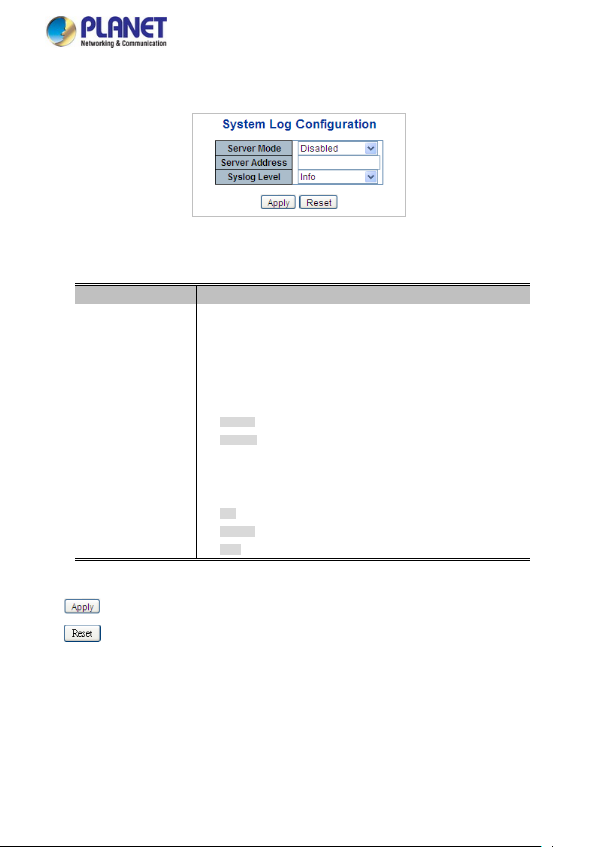
User’s Manual of WGSW Series Managed Switch
74
4.2.1.15 Remote Syslog
Configure remote syslog on this page. The Remote Syslog screen in Figure 4-2-19 appears.
Figure 4-2-19: Remote Syslog Page Screenshot
The page includes the following fields:
Object Description
Buttons
• Mode
• Syslog Server IP
• Syslog Level
Indicates the server mode operation. When the mode operation is enabled, the
syslog message will send out to syslog server. The syslog protocol is based on
UDP communication and r ecei ved on UD P por t 514 and the s yslog server will not
send acknowledgments back sender since UDP is a connectionless protocol and
it does not provide acknowledgments. The syslog packet will always send out
even if the syslog server does not exist. Possible modes are:
Enabled: Enable remote syslog mode operation.
Disabled: Disable remote syslog mode operation.
Indicates the IPv4 host address of syslog server. If the switch provides DNS
feature, it also can be a host name.
Indicates what kind of message will send to syslog server. Possible modes are:
Info: Send information, warnings and errors.
Warning: Send warnings and errors.
Error: Send errors.
: Click to apply changes
: Click to undo any changes made locally and revert to previously saved values.
Page 75
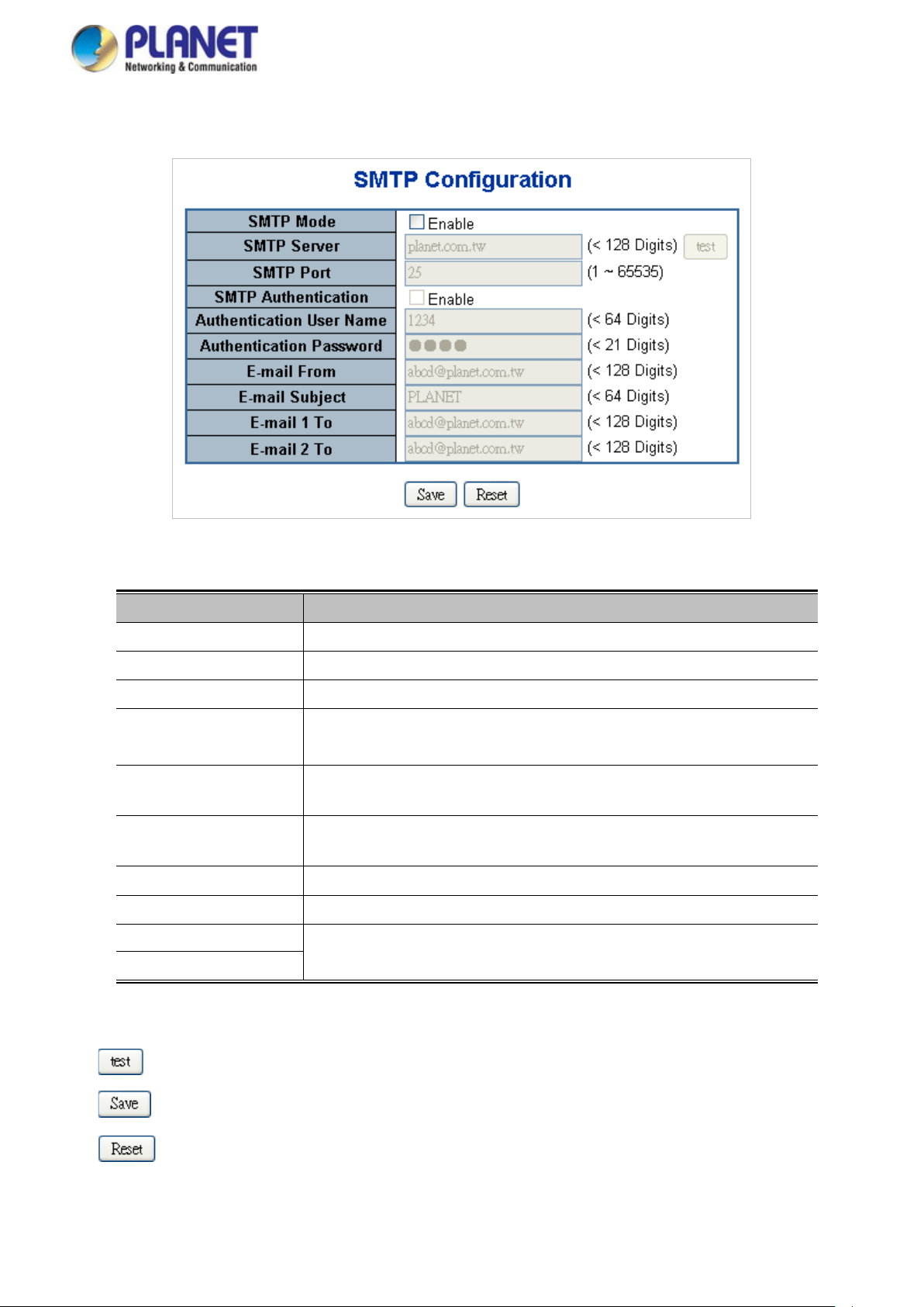
User’s Manual of WGSW Series Managed Switch
75
4.2.1.16 SMTP Configuration
This page facilitates an SMTP Configuration on the switch. The SMTP Configure screen in Figure 4-2-20 appears.
Figure 4-2-20: SMTP Configuration Page Screenshot
The page includes the following fields:
Object Description
• SMTP Mode
• SMTP Server
• SMTP Port
• SMTP Authentication
• Authentication User
Name
• Authentication
Password
• E-mail From
• E-mail Subject
• E-mail 1 To
Controls whether SMTP is enabled on this switch.
Type the SMTP server name or the IP address of the SMTP server.
Set port number of SMTP service.
Controls whether SMTP authentication is enabled if authentication is required
when an e-mail is sent.
Type the user name for the SMTP server if Authentication is Enabled.
Type the password for the SMTP server if Authentication is Enabled.
Type the sender’s e-mail address. This address is used for reply e-mails.
Type the subject/title of the e-mail.
Type the receiver’s e-mail address.
Buttons
• E-mail 2 To
: Send a test mail to mail server to check whether this account is available or not.
: Click to save changes.
: Click to undo any changes made locally and revert to previously saved values.
Page 76

User’s Manual of WGSW Series Managed Switch
76
4.2.2 Simple Network Management Protocol
4.2.2.1 SNMP Overview
The Simple Network M anagement P roto col (SNM P ) is an appli cation l ayer pr otoco l that fa cilitate s th e ex change of manageme nt
information between network devices. It is part of the Transmission Control Protocol/Internet Protocol (TCP/IP) protocol suite.
SNMP enables network administrators to manage network performance, find and solve network problems, and plan for network
growth.
An SNMP-managed network consists of three key components: Network management stations (NMSs), SNMP agents,
Management information base (MIB) and network-management protocol:
■ Network management stations (NMSs): Sometimes called consoles, these devices execute management applications
that monitor and control network elements. Physically, NMSs are usually engineering workstation-caliber comp uter s wi th
fast CPU s, megapixel color displays, substantial memory, and abundant disk space. At least one NMS must be present in
each managed environment.
■ Agents: Agents are software modules that reside in network elements. They collect and store management information
such as the number of error packets received by a network element.
■ Management information base (MIB): A MIB is a collection of managed objects residing in a virtual information store.
Collections of related managed objects are defined in specific MIB modules.
■ Network-management protocol: A management protocol is used to convey management information between agents
and NMSs. SNMP is the Internet community's de facto standard management protocol.
Figure 4-2-2-1:
SNMP Operations
SNMP itself is a simple request/response protocol. NMSs can send multiple requests without receiving a response.
■ Get -- Allows the NMS to retrieve an object instance from the agent.
■ Set -- Allows the NMS to set values for object instances within an agent.
■ Trap -- Used by the agent to asynchronously inform the NMS of some event. The SNMPv2 trap message is designed to
replace the SNMPv1 trap message.
SNMP community
An SNMP community is the group that devices and management stations running SNMP belong to. It helps define where
information is sent. The community name is used to identify the group. An SNMP device or agent may belong to more than one
SNMP community. It will not respond to request s fro m managemen t stat ions t hat do no t belo ng to o ne of it s com munitie s. SNM P
default communities are:
Page 77
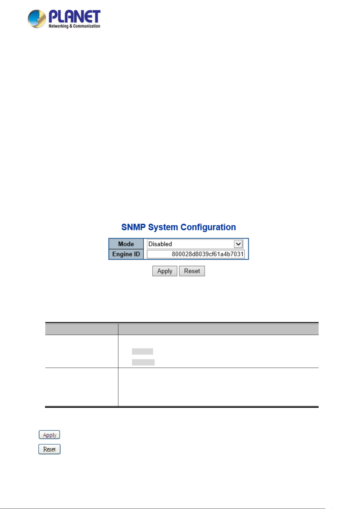
User’s Manual of WGSW Series Managed Switch
77
。 Write = private
。 Read = public
Use the SNMP Menu to display or configure the Managed Switch's SNMP function. This section has the following items:
System Configuration
System Information
SNMP Trap Configuration Configure SNMP trap on this page.
Trap Source Configuration Configure SNMP trap source on this page.
SNMPv3 Communities Configure SNMPv3 communities table on this page.
SNMPv3 Users Configure SNMPv3 users table on this page.
SNMPv3 Groups Configure SNMPv3 groups table on this page.
SNMPv3 Views Configure SNMPv3 views table on this page.
SNMPv3 Access Configure SNMPv3 accesses table on this page.
Configure SNMP on this page.
The system information is provided here.
4.2.2.2 SNMP System Configuration
Configure SNMP on this page. The SNMP System Configuration screen in Figure 4-2-2-2 appears.
Figure 4-2-2-2: SNMP System Configuration Page Screenshot
The page includes the following fields:
Object Description
• Mode
• Engine ID
Buttons
: Click to apply changes
: Click to undo any changes made locally and revert to previously saved values.
Indicates the SNMP mode operation. Possible modes are:
Enabled: Enable SNMP mode operation.
Disabled: Disable SNMP mode operation.
Indicates the SNMPv3 engine ID. The string must contain an even number
between 10 and 64 hexadecimal digits, but all-zeros and all-'F's are not allowed.
Change of the Engine ID will clear all original local users.
Page 78

User’s Manual of WGSW Series Managed Switch
78
4.2.2.3 SNMP System Information
Configure SNMP on this page. The SNMP System information screen in Figure 4-2-2-3 appears.
Figure 4-2-2-3: SNMP System Information Page Screenshot
The page includes the following fields:
Object Description
• System Contact
• System Name
• System Location
The textual identification of the contact person for this managed node, together with
information on how to contact this person. The allowed string length is 0 to 255, and
the allowed content is the ASCII characters from 32 to 126.
An administratively assigned name for this managed node. By convention, this is the
node's fully-qualified domain name. A domain name is a text string drawn from the
alphabet (A-Za-z), digits (0-9), minus sign (-). No space char a cter s are permitted as
part of a name. The first character must be an alpha character. And the first or last
character must not be a minus sign. The allowed string length is 0 to 255.
The physical location of this node(e.g., telephone closet, 3rd floor). The allowed string
length is 0 to 255, and the allowed content is the ASCII characters from 32 to 126.
Page 79
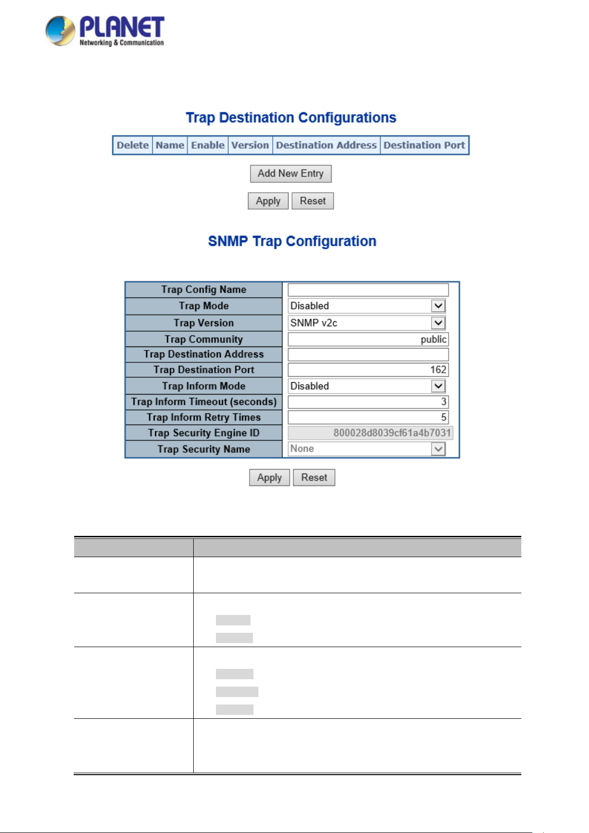
User’s Manual of WGSW Series Managed Switch
79
4.2.2.4 SNMP Trap Configuration
Configure SNMP trap on this page. The SN MP T rap Configur ation screen in Figure 4-2-2-4 appears.
Figure 4-2-2-4: SNMP Trap Configuration Page Screenshot
The page includes the following fields:
Object Description
• Trap Config
• Trap Mode
• Trap Version
• Trap Community
Indicates which trap Configuration's name for configuring. The allowed string
length is 0 to 255, and the allowed content is ASCII characters from 33 to 126.
Indicates the SNMP trap mode operation. Possible modes are:
Enabled: Enable SNMP trap mode operation.
Disabled: Disable SNMP trap mode operation.
Indicates the SNMP trap supported version. Possible versions are:
SNMP v1: Set SNMP trap supported version 1.
SNMP v2c: Set SNMP trap supported version 2c.
SNMP v3: Set SNMP trap supported version 3.
Indicates the community access string when send SNMP trap packet. The
allowed string length is 0 to 255, and the allowed content is the ASCII characters
from 33 to 126.
Page 80

User’s Manual of WGSW Series Managed Switch
80
using USM for authentication and privacy. A unique engine ID for these traps and
for authentication and privacy. A unique security name is needed when traps and
• Trap Destination
Address
• Trap Destination Port
• Trap Inform Mode
• Trap Inform Timeout
(seconds)
• Trap Inform Retry
Times
• Trap Security Engine
ID
Indicates the SNMP trap destination address.
Indicates the SNM P tr ap d est i natio n port. SNMP Agent will send SNMP message
via this port, the port range is 1~65535.
Indicates the SNMP trap inform mode operation. Possible modes are:
Enabled: Enable SNMP trap authentication failure.
Disabled: Disable SNMP trap authentication failure.
Indicates the SNMP trap inform timeout.
The allowed range is 0 to 2147.
Indicates the SNMP trap inform retry times.
The allowed range is 0 to 255.
Indicates the SNMP trap security engine ID. SNMPv3 sends traps and informs
informs is needed. When "Trap Probe Security Engine ID" is enabled, the ID will
be probed automatically. Otherwise, the ID specified in this field is used. The
string must contain an ev en nu mber(i n hexadecimal format) with number of digits
• Trap Security Name
• System
• Interface
• AAA
• Switch
between 10 and 64, but all-zeros and all-'F's are not allowed.
Indicates the SNMP trap security name. SNMPv3 traps and informs using USM
informs are enabled.
Enable/disable that the Interface group's traps. Possible traps are:
Warm Start: Enable/disable Warm Start trap.
Cold Start: Enable/disable Cold Start trap.
Indicates that the Interface group's traps. Possible traps are:
Link Up: Enable/disa ble Lin k up trap.
Link Down: Enable/disable Link down trap.
LLDP: Enable/disable LLDP trap.
Indicates that the AAA group's traps. Possible traps are:
Authentication Fail : Enable/disable SNMP trap authentication failure trap.
Indicates that the Switch group's traps. Possible traps are:
STP: Enable/disable STP trap.
RMON: Enable/disable RMON trap .
Buttons
: Click to apply changes
: Click to undo any changes made locally and revert to previously saved values.
Page 81

User’s Manual of WGSW Series Managed Switch
81
4.2.2.5 SNMP Trap Source Configuration
Configure SNMP trap on this page. The SN MP T rap Configur ation screen in Figure 4-2-2-5 appears.
Figure 4-2-2-5: SNMP Trap Source Configuration Page Screenshot
The page includes the following fields:
Object Description
• Delete
• Name
• Type
Check to delete the entry. It will be deleted during the next save.
Povide the name of all options that can choosed, the available options ar e shown
as below:
coldStart
linkup
linkDown
authenticationFailure
newRoot
topologyChange
lldpRemTablesChange
Povide the type of all options that can choosed, the available options are shown
as below:
included
• Subset OID
excluded
Display the subset OID information.
Page 82

User’s Manual of WGSW Series Managed Switch
82
Buttons
: Click to add a new community entry.
: Click to apply changes
: Click to undo any changes made locally and revert to previously saved values.
4.2.2.6 SNMPv3 Communities
Configure SNMPv3 communities table on this page. The entry index key is Community. The SNMPv3 Communities screen in
Figure 4-2-2-6 appears.
Figure 4-2-2-6: SNMPv3 Communities Configuration Page Screenshot
The page includes the following fields:
Object Description
• Delete
• Community Name
• Community Secret
• Source IP
• Source Prefix
Check to delete the entry. It will be deleted during the next save.
Indicates the community access string to permit access to SNMPv3 agent. The
allowed string length is 1 to 32, and the allowed content is ASCII characters from
33 to 126. The community string will be treated as security name and map a
SNMPv1 or SNMPv2c community string.
Display the community access string to permit access to SNMPv3 agent.
Indicates the SNMP access source address. A particular range of source
addresses can be used to restrict source subnet when combined with source
mask.
Indicates the SNMP access source prefix.
Buttons
: Click to add a new community entry.
: Click to apply changes
: Click to undo any changes made locally and revert to previously saved values.
Page 83

User’s Manual of WGSW Series Managed Switch
83
4.2.2.7 SNMPv3 Users
Configure SNMPv3 users tabl e on this page. The entry index keys ar e Engine ID and User Name. The SNMPv3 Users screen in
Figure 4-2-2-7 appears.
Figure 4-2-2-7: SNMPv3 Users Configuration Page Screenshot
The page includes the following fields:
Object Description
• Delete
• Engine ID
• User Name
Check to delete the entry. It will be deleted during the next save.
An octet string identifying the engine ID that this entry should belong to. The
string must contain an ev en nu mber(i n hexadecimal format) with number of digits
between 10 and 64, but all-zeros and all-'F's are not allowed. The SNMPv3
architecture uses the User-based Security Model (USM) for message security
and the View-based Access Control Model (VACM) for access control. For the
USM entry, the usmUserEngineID and usmUserName are the entry's keys.
In a simple agent, usmUserEngineID is always that agen t's own snmpEngineID
value. The value can also tak e the v alue of the sn mpEngine I D of a remote SN M P
engine with which this user can communicate. In other words, if user engine ID
equal system engine ID then it is local user; otherwise it's remote user.
A string identifying the user name that this entry should belong to. The allowed
string length is 1 to 32, and the allowed content is ASCII characters from 33 to
126.
• Security Level
Indicates the security model that this entry should belong to. Possible security
models are:
NoAuth, NoPriv: None authentication and none privacy.
Auth, NoPriv: Authentication and none privacy.
Auth, Priv: Authentication and privacy.
The value of security level cannot be modified if entry already exist. That means
must first ensure that the value is set correctly.
Page 84

User’s Manual of WGSW Series Managed Switch
84
allowed string length is 8 to 40. The allowed content is the ASCII characters from
• Authentication
Protocol
• Authentication
Password
• Privacy Protocol
Indicates the authentication protocol that this entry should belong to. Possible
authentication protocol are:
None: None authentication protocol.
MD5: An optional flag to indicate that this user using MD5 authentication
protocol.
SHA: An optional flag to indicate that this user using SHA authentication
protocol.
The value of security level cannot be modified if entry already exist. That means
must first ensure that the value is set correctly.
A string identifying the authentication pass phrase. For MD5 authentication
protocol, the allow ed str ing le n gt h i s 8 to 32. For SHA authentication protocol, the
33 to 126.
Indicates the privacy protocol that this entry should belong to. Possible privacy
protocol are:
None: None privacy protocol.
DES: An optional flag to indicate that this user using DES authentication
Buttons
protocol.
AES: An optional flag to indicate that this user uses AES authentication
protocol.
• Privacy Password
: Click to add a new user entry.
: Click to apply changes
: Click to undo any changes made locally and revert to previously saved values.
A string ident ify ing the priv acy pas s phrase . T he allowed string length is 8 to 32,
and the allowed content is the ASCII characters from 33 to 126.
Page 85

User’s Manual of WGSW Series Managed Switch
85
4.2.2.8 SNMPv3 Groups
Configure SNMPv3 groups table on this page. The entry index keys are Security Model and Security Name. The SNMPv3
Groups screen in Figure 4-2-2-8 appears.
Figure 4-2-2-8: SNMPv3 Groups Configuration Page Screenshot
The page includes the following fields:
Buttons
Object Description
• Delete
• Security Model
Check to delete the entry. It will be deleted during the next save.
Indicates the security model that this entry should belong to. Possible security
models are:
v1: Reserved for SNMPv1.
v2c: Reserved for SNMPv2c.
usm: User-based Security Model (USM).
• Security Name
• Group Name
A string identifying the security name that this entry should belong to.
The allowed string length is 1 to 32, and the allowed content i s the ASCII
characters from 33 to 126.
A string identifying the group name that this entry should belong to.
The allowed string length is 1 to 32, and the allowed content is the ASCII
characters from 33 to 126.
: Click to add a new group entry.
: Click to apply changes
: Click to undo any changes made locally and revert to previously saved values.
Page 86

User’s Manual of WGSW Series Managed Switch
86
4.2.2.9 SNMPv3 Views
Configure SNMPv3 views table on this page. The entry index keys are V iew Name and OID Subtree. The SNMPv3 Views
screen in Figure 4-2-2-10 appears.
Figure 4-2-2-8: SNMPv3 Views Configuration Page Screenshot
The page includes the following fields:
Object Description
Buttons
• Delete
• View Name
• View Type
• OID Subtree
Check to delete the entry. It will be deleted during the next save.
A string identifying the view name that this entry should belong to. The allowed
string length is 1 to 32, and the allowed content is the ASCII characters from 33
to 126.
Indicates the view type that this entry should belong to. Possible view type are:
included: An optional flag to indicate that this view subtree should be
included.
excluded: An optional flag to indicate that this view subtree should be
excluded.
In general, if a view entr y 's v ie w type is 'excluded', it s hou ld b e exist another view
entry which view type is 'included' and it's OID subtree overstep the 'excluded'
view entry.
The OID defining the root of the subtree to add to the named view. The allowed
OID length is 1 to 128. The allowed string content is digital number or asterisk(*).
: Click to add a new view entry.
: Click to apply changes
: Click to undo any changes made locally and revert to previously saved values.
Page 87

User’s Manual of WGSW Series Managed Switch
87
4.2.2.10 SNMPv3 Access
Configure SNMPv3 accesses table on this page. The entry index keys are Group Name, Security Model and Security Level.
The SNMPv3 Access screen in Figure 4-2-2-11 appears.
Figure 4-2-2-11: SNMPv3 Accesses Configuration Page Screenshot
The page includes the following fields:
Object Description
• Delete
• Group Name
• Security Model
• Security Level
• Read View Name
Check to delete the entry. It will be deleted during the next save.
A string identifying the group name that this entry should belong to. The allowed
string length is 1 to 32, and the allowed content is the ASCII characters from 33
to 126.
Indicates the security model that this entry should belong to. Possible security
models are:
any: Accepted any security model (v1|v2c|usm).
v1: Reserved for SNMPv1.
v2c: Reserved for SNMPv2c.
usm: User-based Security Model (USM)
Indicates the security model that this entry should belong to. Possible security
models are:
NoAuth, NoPriv: None authentication and none privacy.
Auth, NoPriv: Authentication and none priv acy.
Auth, Priv: Authentication and privacy.
The name of the MIB view defining the MIB objects for which this request may
Buttons
• Write View Name
: Click to add a new access entry.
: Click to apply changes
request the current values. The allowed string length is 1 to 32, and the allowed
content is the ASCII characters from 33 to 126.
The name of the MIB view defining the MIB objects for which this request may
potentially SET new values. The allowed string length is 1 to 32, and the allowed
content is the ASCII characters from 33 to 126.
Page 88

User’s Manual of WGSW Series Managed Switch
88
: Click to undo any changes made locally and revert to previously saved values.
4.2.3 RMON
RMON is the most important expansion of the standard SNMP. RMON is a set of MIB definitions, used to define standard
network monitor functions and interfaces, enabling the communication between SNMP management terminals and remote
monitors. RMON provides a highly efficient method to monitor actions inside the subnets.
MID of RMON consists of 10 groups. The switch supports the most frequently used groups 1, 2, 3 and 9:
Statistics: Maintain basic usage and error statistics for each subnet monitored by the agent.
History: Record periodical statistic samples available from statistics.
Alarm: Allow management console users to set any count or integer for sample intervals and alert thresholds for
RMON agent records.
Event: A list of all events generated by RMON agent.
Alarm depends on the implementation of Event. Statistics and History display some current or history subnet statistics. Alarm
and Event provide a method to monitor any integer data change in the network, and provide some alerts upon abnormal events
(sending Trap or record in logs).
4.2.3.1 RMON Alarm Configuration
Configure RMON Alarm table on this page. The entry index key is ID.; screen in Figure 4-2-3-1 appears.
Figure 4-2-3-1: RMON Alarm Configuration Page Screenshot
The page includes the following fields:
Object Description
• Delete
• ID
• Interval
• Variable
Check to delete the entry. It will be deleted during the next save.
Indicates the index of the entry. The range is from 1 to 65535.
Indicates the interval in seconds for sampling and comparing the rising and
falling threshold. The range is from 1 to 2^31-1.
Indicates the particular variable to be sampled; the possible variables are:
InOctets: The total number of octets received on the interface, including
framing characters.
InUcastPkts: The number of uni-cast pac ket s deliv ere d to a higher -layer
protocol.
Page 89

User’s Manual of WGSW Series Managed Switch
89
InNUcastPkts: T he number of broadcast and mult i-c ast p ac k et s de liver ed to
a higher-layer protocol.
InDiscards: The number of inbound packets that are discarded even the
packets are normal.
InErrors: The number of inbound packets that contains errors preventing
them from being deliverable to a higher-layer protocol.
InUnknownProtos: the number of the inbound packets that is discarded
because of the unknown or un-support protocol.
OutOctets: The number of octets transmitted out of the interface, including
framing characters.
OutUcastPkts: The number of uni-cast packets that requests to transmit.
OutNUcastPkts: The number of broadcast and multi-cast packets that
requests to transmit.
OutDiscards: The number of outbound packets that is discarded even the
packets are normal.
• Sample Type
• Value
• Startup Alarm
• Rising Threshold
• Rising Index
OutErrors: The number of outbound packets that could not be transmitted
because of errors.
OutQLen: The length of the output packet queue (in packets).
The method of sampling the selected variable and calculating the value to be
compared against the thresholds; possible sample types are:
Absolute: Get the sample directly.
Delta: Calculate the differen ce between samples (default).
The value of the statistic during the last sampling period.
The method of sampling the selected variable and calculating the value to be
compared against the thresholds; possible sample types are:
RisingTrigger alarm when the first value is larger than the rising threshold.
FallingTrigger alarm when the first value is less than the falling threshold.
RisingOrFallingTrigger alarm when the first value is larger than the rising
threshold or less than the falling threshold (default).
Rising threshold value (-2147483648-2147483647).
Rising event index (1-65535).
Buttons
• Falling Threshold
• Falling Index
: Click to add a new community entry.
: Click to apply changes
: Click to undo any changes made locally and revert to previously saved values.
Falling threshold value (-2147483648-2147483647)
Falling event index (1-65535).
Page 90
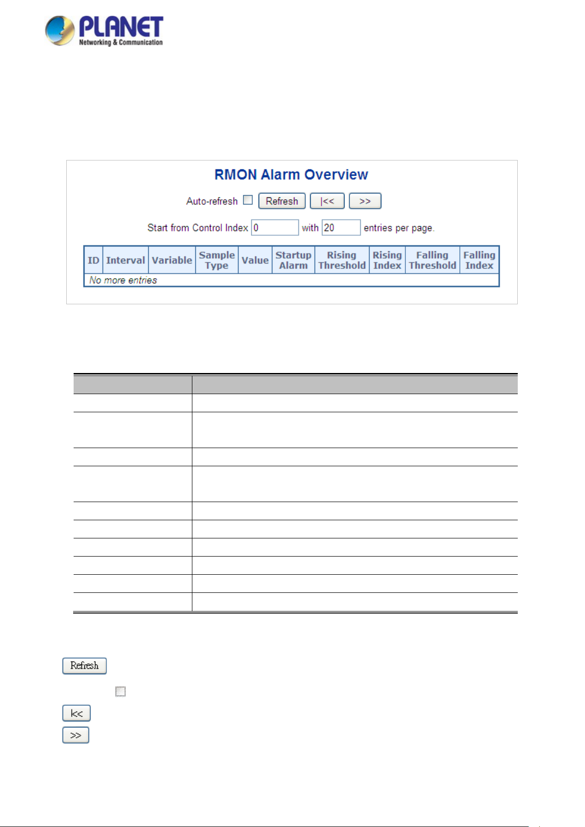
User’s Manual of WGSW Series Managed Switch
90
4.2.3.2 RMON Alarm Status
This page provides an overview of RMON Alarm entries. Each page shows up to 99 entries from the Alarm table, default being
20, selected through the "entries per page" input field. When first visited, the web page will show the first 20 entries from the
beginning of the Alarm table. The first displayed will be the one with the lowest ID found in the Alarm table; screen in Figure
4-2-3-2 appears.
Figure 4-2-3-2: RMON Alarm Overview Page Screenshot
The page includes the following fields:
Object Description
• ID
• Interval
• Variable
• Sample Type
• Value
• Startup Alarm
• Rising Threshold
• Rising Index
• Falling Threshold
• Falling Index
Indicates the index of Alarm control entry.
Indicates the interval in seconds for sampling and comparing the rising and
falling threshold.
Indicates the particular variable to be sampled.
The method of sampling the selected variable and calculating the value to be
compared against the thresholds.
The value of the statistic during the last sampling period.
The alarm that may be sent when this entry is first set to valid.
Rising threshold value
Rising event index
Falling threshold value
Falling event index
Buttons
: Click to refresh the page immediately.
Auto-refresh : Check this box to refresh the page automatically. Automatic refresh occurs every 3 seconds.
: Updates the table, starting from the first entry in the Alarm Table, i.e. the entry with the lowest ID.
: Updates the table, starting with the entry after the last entry currently displayed.
Page 91

User’s Manual of WGSW Series Managed Switch
91
4.2.3.3 RMON Event Configuration
Configure RMON Event table on this page. The entry index key is ID; screen in Figure 4-2-3-3 appears.
Figure 4-2-3-3 RMON Event Configuration Page Screenshot
The page includes the following fields:
Object Description
Buttons
• Delete
• Alarm ID
• Desc
• Type
• Event Last Time
Check to delete the entry. It will be deleted during the next save.
Indicates the index of the entry. The range is from 1 to 65535.
Indicates this event, the string length is from 0 to 127, default is a null string.
Indicates the notification of the event; the possible types are:
none: The total number of octets receiv ed on the interface, including framing
characters.
log: The number of uni-cast packets delivered to a higher-layer protocol.
snmptrap: The numb er of bro ad-cast and multi-cast packets delivered to a
higher-layer protocol.
logandtrap: The number of inbound packets that are discarded even the
packets are normal.
Indicates the value of sysUpTime at the time this event entry last generated an
event.
: Click to add a new community entry.
: Click to apply changes
: Click to undo any changes made locally and revert to previously saved values.
Page 92

User’s Manual of WGSW Series Managed Switch
92
4.2.3.4 RMON Event Status
This page provides an overview of RMON Event table entries. Each page shows up to 99 entries from the Event table, default
being 20, selected through the "entries per page" input field. When first visited, the web page will show the first 20 entries from
the beginning of the Ev ent tab le. T he fir st disp layed w ill b e the one w ith t he low est Ev ent In dex and Log Index found in t he Event
table; screen in Figure 4-2-3-4 appears.
Figure 4-2-3-4: RMON Event Overview Page Screenshot
The page includes the following fields:
Object Description
• Event Index
• Log Index
• Logtime
• Log Description
Buttons
: Click to refresh the page immediately.
Auto-refresh : Check this box to refresh the page automatically. Automatic refresh occurs every 3 seconds.
: Updates the table starting from the first entry in the Alarm Table, i.e. the entry with the lowest ID.
: Updates the table, starting with the entry after the last entry currently displayed.
Indicates the index of the event entry.
Indicates the index of the log entry.
Indicates Event log time.
Indicates the Event description.
: Updates the table, starting with the entry after the last entry currently displayed.
Page 93
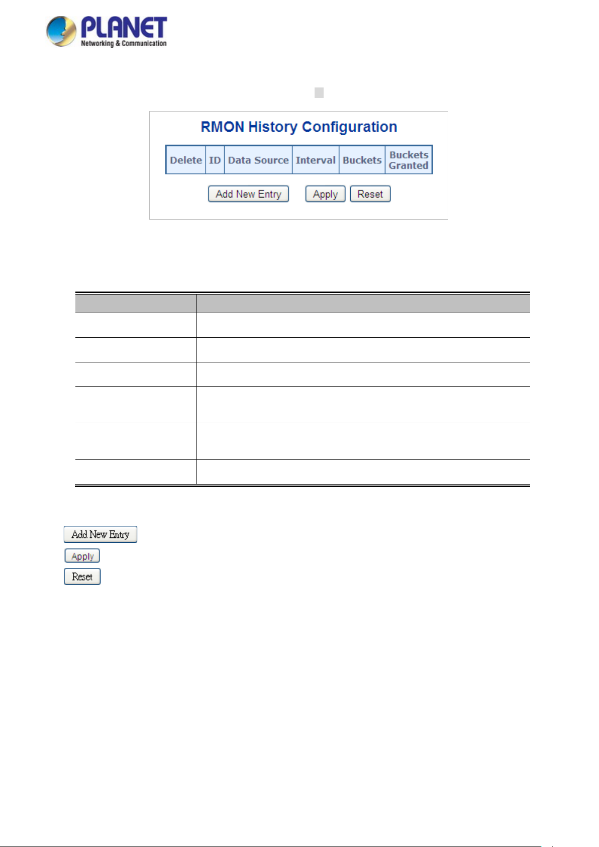
User’s Manual of WGSW Series Managed Switch
93
4.2.3.5 RMON History Configuration
Configure RMON History table on this page. The entry index key is ID; screen in Figure 4-2-3-5 appears.
Figure 4-2-3-5: RMON History Configuration Page Screenshot
The page includes the following fields:
Object Description
Buttons
• Delete
• ID
• Data Source
• Interval
• Buckets
• Buckets Granted
: Click to add a new community entry.
: Click to apply changes
: Click to undo any changes made locally and revert to previously saved values.
Check to delete the entry. It will be deleted during the next save.
Indicates the index of the entry. The range is from 1 to 65535.
Indicates the port ID which wants to be monitored.
Indicates the interval in seconds for sampling the history statistics data. The
range is from 1 to 3600, default value is 1800 seconds.
Indicates the maximum data entries associated this History control entry stored
in RMON. The range is from 1 to 3600, default value is 50.
The number of data will be saved in the RMON.
Page 94

User’s Manual of WGSW Series Managed Switch
94
4.2.3.6 RMON History Status
This page provides an detail of RMON history entries; screen in Figure 4-2-3-6 appears.
Figure 4-2-3-6: RMON History Overview Page Screenshot
The page includes the following fields:
Object Description
• History Index Indicates the index of History control entry.
• Sample Index Indicates the index of the data entry associated with the control entry.
• Sample Start The value of sysUpTime at the start of the interval over which this sample was
measured.
• Drop The total number of events in which packets were dropped by the probe due to
lack of resources.
• Octets The total number of octets of data (including those in bad packets) received on
the network.
• Pkts The total number of packets (including bad packets, broadcast packets, and
multicast packets) received.
• Broadcast The total number of good packets received that were directed to the broadcast
address.
• Multicast The total number of good packets received that were directed to a multicast
address.
CRC Errors The total number of packets received that had a length (excluding framing bits,
but including FCS octets) of between 64 and 1518 octets, inclusive, but had
either a bad Frame Check Sequence (FCS) with an integral number of octets
(FCS Error) or a bad FCS with a non-integral number of octets (Alignment Error).
• Undersize The total number of packets received that were less than 64 octets.
• Oversize The total number of packets received that were longer than 1518 octets.
• Frag. The number of frames whose size is less than 64 octets received with invalid
CRC.
• Jabb. The number of frames whose size is larger than 64 octets received with invalid
CRC.
• Coll. T he best estima te of the tota l number of colli sions in this Ethernet segment.
• Utilization The best estimate of the mean physical layer network utilization on this interface
during this sampling interval, in hundredths of a percent.
Page 95
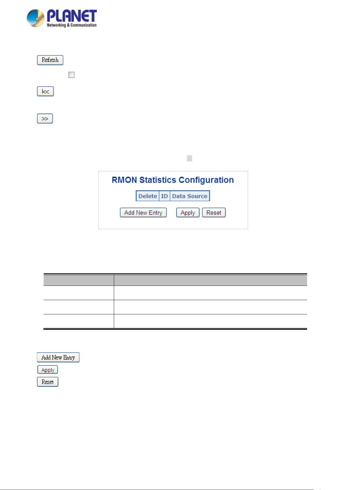
User’s Manual of WGSW Series Managed Switch
95
Buttons
: Click to refresh the page immediately.
Auto-refresh : Check this box to refresh the page automatically. Automatic refresh occurs every 3 seconds.
: Updates the table, starting from the first entry in the History table, i.e., the entry with the lowest History
Index and Sample Index
: Updates the table, starting with the entry after the last entry currently displayed.
4.2.3.7 RMON Statistics Configuration
Configure RMON Statistics table on this page. The entry index key is ID; screen in Figure 4-2-3-7 appears.
Figure 4-2-3-7: RMON Statistics Configuration Page Screenshot
The page includes the following fields:
Object Description
• Delete
• ID
• Data Source
Buttons
: Click to add a new community entry.
: Click to apply changes
: Click to undo any changes made locally and revert to previously saved values.
Check to delete the entry. It will be deleted during the next save.
Indicates the index of the entry. The range is from 1 to 65535.
Indicates the port ID which wants to be monitored.
Page 96

User’s Manual of WGSW Series Managed Switch
96
4.2.3.8 RMON Statistics Status
This page provides an overview of RMON Statistics entries. Each page shows up to 99 entries from the Statistics table, default
being 20, selected through the "entries per page" input field. When first visited, the web page will show the first 20 entries from
the beginning of the Statistics table. The first displayed will be the one with the lowest ID found in the Statistics table; screen in
Figure 4-2-3-8 appears.
Figure 4-2-3-8: RMON Statistics Status Overview Page Screenshot
The page includes the following fields:
Object Description
• ID
• Data Source (ifIndex)
• Drop
• Octets
• Pkts
• Broadcast
• Multicast
• CRC Errors
Indicates the index of Statistics entry.
The port ID which wants to be monitored.
The total number of events in which packets were dropped by the probe due to
lack of resources.
The total number of octets of data (including those in bad packets) received on
the network.
The total number of packets (including bad packets, broadcast packets, and
multicast packets) received.
The total number of good packets received that were directed to the broadcast
address.
The total number of good packets received that were directed to a multicast
address.
The total number of packets received that had a length (excluding framing bit s,
but including FCS octets) of between 64 and 1518 octets.
• Undersize
• Oversize
• Frag.
• Jabb.
• Coll.
The total number of packets received that were less than 64 octets.
The total number of packets received that were longer than 1518 octets.
The number of frames whose size is less than 64 octets received with invalid
CRC.
The number of frames whose size is larger than 64 octets received with invalid
CRC.
The best estimate of the total number of collisions in this Ethernet segment.
Page 97

User’s Manual of WGSW Series Managed Switch
97
• 64 Bytes
• 65~127
• 128~255
• 256~511
• 512~1023
• 1024~1518
Buttons
: Click to refresh the page immediately.
Auto-refresh : Check this box to refresh the page automatically. Automatic refresh occurs every 3 seconds.
The total number of packets (i nclu din g bad pa ck ets) r e ce iv ed that were 64 octets
in length.
The total number of packets (including bad packets) received that were between
65 to 127 octets in length.
The total number of packets (including bad packets) received that were between
128 to 255 octets in length.
The total number of packets (including bad packets) received that were between
256 to 511 octets in length.
The total number of packets (including bad packets) received that were between
512 to 1023 octets in length.
The total number of packets (including bad packets) received that were between
1024 to 1518 octets in length.
: Updates the table, starting from the first entry in the Alarm Table, i.e. the entry with the lowest ID.
: Updates the table, starting with the entry after the last entry currently displayed.
Page 98

User’s Manual of WGSW Series Managed Switch
98
4.2.4 DHCP server
4.2.4.1 DHCP Server Mode Configuration
Configure DHCP server mode on this page. The entry index key is ID.; screen in Figure 4-2-4-1 appears.
Figure 4-2-4-1: DHCP server mode Page Screenshot
The page includes the following fields:
Object Description
• Mode
• VLAN Mode
• VLAN Range
Configure the operation mode per system. Possib le mod es a re:
Enabled: Enable DHCP server per system.
Disabled: Disable DHCP server pre system.
Configure operation mode to enable/disable DHCP server per VLAN.
Indicate the VLAN range in which DHCP server is enabled or disabled. The first
VLAN ID must be smaller th an or equal to the second VLA N ID. BUT, if the VLAN
range contains only 1 VLAN ID, then you can just input it into either one of the
first and second VLAN ID or both.
On the other hand, if you want to disable existed VLAN range, then you can
follow the steps.
1. press to add a new VLAN range.
2. input the VLAN range that you want to disable.
3. choose Mode to be Disabled.
4. press to apply the change.
Then, you will see the disabled VLAN range is removed from the DHCP Server
mode configuration page.
• Mode Indicate the operation mode per VLAN. Possible modes are:
Enabled: Enable DHCP server per VLAN.
Disabled: Disable DHCP server pre VLAN.
Page 99

User’s Manual of WGSW Series Managed Switch
99
Buttons
: Click to add a new VLAN range.
: Click to apply changes
: Click to undo any changes made locally and revert to previously saved values.
4.2.4.2 DHCP Server excluded IP Configuration
Configure DHCP server mode on this page. The en try index key is ID.; screen in Figure 4-2-4-2 appears.
Figure 4-2-4-2: DHCP server excluded Page Screenshot
The page includes the following fields:
Object Description
• IP range
Buttons
: Click to add a new excluded IP range.
: Click to apply changes
: Click to undo any changes made locally and revert to previously saved values.
Define the IP range to be excluded IP addresses. The first excluded IP must be
smaller than or equal to the second excluded IP. BUT, if the IP range contains
only 1 excluded IP, then you can just input it to either one of the first and second
excluded IP or both.
Page 100

User’s Manual of WGSW Series Managed Switch
100
4.2.4.3 DHCP Server pool Configuration
This page manages DHCP pools. According to the DHCP pool, DHCP server will allocate IP address and deliver configuration
parameters to DHCP client. screen in Figure 4-2-4-3 appears.
Figure 4-2-4-3: DHCP server pool Page Screenshot
The page includes the following fields:
Object Description
• Delete
• Name
• Type
• IP
• Subnet Mask
Check to delete the entry. It will be deleted during the next save.
Configure the pool name that accepts all printable characters, except white
space. If you want to configure the detail settings, you can click the pool name to
go into the configuration page.
Display which type of the pool is.
Network: the pool defines a p ool of IP addre ss es to serv ice more than one
DHCP client.
Host: the pool services for a specific DHCP client identified by client identifier or
hardware address.
Display network number of the DHCP address pool.
If "-" is displayed, it means not defined
Display subnet mask of the DHCP address pool.
If "-" is displayed, it means not defined.
Buttons
• Lease Time
: Click to add a new excluded IP range.
: Click to apply changes
: Click to undo any changes made locally and revert to previously saved values.
Display lease time of the pool.
 Loading...