

Page 1

WGS3-24000
User’s Manual of WGS3-24000 / WGS3-24240
User's Manual
WGS3-24240
24-Port Gigabit
Layer 3 Managed Ethernet Switch
1
Page 2

User’s Manual of WGS3-24000 / WGS3-24240
Trademarks
Copyright © PLANET Technology Corp. 2008.
Contents subject to which revision without prior notice.
PLANET is a registered trademark of PLANET Technology Corp. All other trademarks belong to their respective owners.
Disclaimer
PLANET Technology does not warrant that the hardware will work properly in all environments and applications, and makes no
warranty and representation, either implied or expressed, with respect to the quality, performance, merchantability, or fitness for
a particular purpose.
PLANET has made every effort to ensure that this User's Manual is accurate; PLANET disclaims liability for any inaccuracies or
omissions that may have occurred.
Information in this User's Manual is subject to change without notice and does not represent a commitment on the part of
PLANET. PLANET assumes no responsibility for any inaccuracies that may be contained in this User's Manual. PLANET makes
no commitment to update or keep current the information in this User's Manual, and reserves the right to make improvements to
this User's Manual and/or to the products described in this User's Manual, at any time without notice.
If you find information in this manual that is incorrect, misleading, or incomplete, we would appreciate your comments and
suggestions.
FCC Warning
This equipment has been tested and found to comply with the limits for a Class A digital device, pursuant to Part 15 of the FCC
Rules. These limits are designed to provide reasonable protection against harmful interference when the equipment is operated
in a commercial environment. This equipment generates, uses, and can radiate radio frequency energy and, if not installed and
used in accordance with the Instruction manual, may cause harmful interference to radio communications. Operation of this
equipment in a residential area is likely to cause harmful interference in which case the user will be required to correct the
interference at whose own expense.
CE Mark Warning
This is a Class A product. In a domestic environment, this product may cause radio interference, in which case the user may be
required to take adequate measures.
WEEE Warning
To avoid the potential effects on the environment and human health as a result of the presence of
hazardous substances in electrical and electronic equipment, end users of electrical and electronic
equipment should understand the meaning of the crossed-out wheeled bin symbol. Do not dispose of
WEEE as unsorted municipal waste and have to collect such WEEE separately.
Revision
PLANET 24-Port Gigaibt Layer 3 Managed Ethernet Switch User's Manual
FOR MODELS: WGS3-24000 / WGS3-24240
REVISION: 1.2(June.2008)
Part No. : EM-WGS3-24000_24240_v1.2 (2081-A96020-003)
2
Page 3

User’s Manual of WGS3-24000 / WGS3-24240
Table of Contents
1. INTRODUCTION.................................................................................................................. 19
1.1 Packet Contents ............................................................................................................................................................19
1.2 Product Description .......................................................................................................................................................19
1.3 How to Use This Manual................................................................................................................................................21
1.4 Product Features ...........................................................................................................................................................22
1.5 Product Specification.....................................................................................................................................................24
2. INSTALLATION .................................................................................................................... 26
2.1 Hardware Description ....................................................................................................................................................26
2.1.1 Switch Front Panel............................................................................................................................................26
2.1.2 LED Indications.................................................................................................................................................27
2.1.3 Switch Rear Panel ............................................................................................................................................28
2.2 Install the Switch............................................................................................................................................................29
2.2.1 Desktop Installation...........................................................................................................................................29
2.2.2 Rack Mounting..................................................................................................................................................29
2.2.3 Installing the SFP transceiver ...........................................................................................................................31
3. SWITCH MANAGEMENT ....................................................................................................33
3.1 Requirements ................................................................................................................................................................33
3.2 Management Access Overview .....................................................................................................................................34
3.3 Administration Console ..................................................................................................................................................34
3.4 Web Management .........................................................................................................................................................35
3.5 SNMP-Based Network Management.............................................................................................................................36
3.6 Protocols........................................................................................................................................................................36
3.6.1 Virtual Terminal Protocols .................................................................................................................................36
3.6.2 SNMP Protocol .................................................................................................................................................36
3.6.3 Management Architecture .................................................................................................................................36
4. WEB CONFIGURATION ...................................................................................................... 37
4.1 Main Menu.....................................................................................................................................................................40
4.2 Configure System ..........................................................................................................................................................42
4.2.1 ARP Cache .......................................................................................................................................................42
4.2.2 Inventory Information ........................................................................................................................................43
4.2.3 Configuration ....................................................................................................................................................44
4.2.4 Forwarding Database........................................................................................................................................57
4.2.5 Log....................................................................................................................................................................59
4.2.6 Port ...................................................................................................................................................................66
4.2.7 SNMP ...............................................................................................................................................................74
4.2.8 Statistics............................................................................................................................................................78
3
Page 4

User’s Manual of WGS3-24000 / WGS3-24240
4.2.9 System Utilities .................................................................................................................................................88
4.2.10 Trap Management...........................................................................................................................................93
4.2.11 DHCP Server ..................................................................................................................................................95
4.2.12 SNTP ............................................................................................................................................................104
4.3 Switching ..................................................................................................................................................................... 111
4.3.1 VLAN .............................................................................................................................................................. 111
4.3.2 Protocol-based VLAN .....................................................................................................................................11 9
4.3.3 Port Security ...................................................................................................................................................122
4.3.4 GARP..............................................................................................................................................................130
4.3.5 IGMP Snooping...............................................................................................................................................133
4.3.6 Port Channel...................................................................................................................................................144
4.3.7 Multicast Forwarding Database.......................................................................................................................149
4.3.8 Spanning Tree.................................................................................................................................................153
4.3.9 Class of Service..............................................................................................................................................170
4.4 Security........................................................................................................................................................................172
4.4.1 Port Access Control ........................................................................................................................................175
4.4.2 RADIUS ..........................................................................................................................................................184
4.4.3 TACACS+ .......................................................................................................................................................196
4.4.4 Secure HTTP ..................................................................................................................................................198
4.4.5 Secure Shell ...................................................................................................................................................199
4.5 QoS .............................................................................................................................................................................201
4.5.1 IP Access Control List .....................................................................................................................................201
4.5.2 MAC Access Control List ................................................................................................................................208
4.5.3 ACL Interface Configuration ............................................................................................................................213
4.5.4 Differentiated Services....................................................................................................................................215
4.5.5 Class of Service..............................................................................................................................................227
4.6 Routing ........................................................................................................................................................................235
4.6.1 IP ....................................................................................................................................................................238
4.6.2 VLAN Routing .................................................................................................................................................245
4.6.3 RIP..................................................................................................................................................................248
4.6.4 OSPF ..............................................................................................................................................................257
4.6.5 Router .............................................................................................................................................................285
4.6.6 ARP ................................................................................................................................................................291
4.6.7 BOOTP/DHCP Relay Agent............................................................................................................................295
4.6.8 Router Discovery ............................................................................................................................................297
4.6.9 VRRP..............................................................................................................................................................300
4.7 IP Multicast ..................................................................................................................................................................309
4.7.1 Multicast..........................................................................................................................................................309
4.7.2 IGMP...............................................................................................................................................................316
4.7.3 DVMRP...........................................................................................................................................................324
4
Page 5

User’s Manual of WGS3-24000 / WGS3-24240
4.7.4 Mdebug...........................................................................................................................................................333
4.7.5 PIM-DM...........................................................................................................................................................340
4.7.6 PIM-SM...........................................................................................................................................................345
5. COMMAND STRUCTURE ................................................................................................. 353
5.1 Format .........................................................................................................................................................................353
5.1.1 Command .......................................................................................................................................................353
5.1.2 Parameters .....................................................................................................................................................353
5.1.3 Values .............................................................................................................................................................353
5.1.4 Conventions....................................................................................................................................................354
5.1.5 Annotations .....................................................................................................................................................354
6. QUICK START UP .............................................................................................................355
6.1 Quick Starting the Switch.............................................................................................................................................355
6.2 System Info and System Setup ...................................................................................................................................355
7. MODE-BASED CLI ............................................................................................................ 360
7.1 Mode-Based Topology.................................................................................................................................................361
7.2 Mode-based Command Hierarchy...............................................................................................................................362
7.3 Flow of Operation ........................................................................................................................................................364
7.4 "No" Form of a Command............................................................................................................................................365
7.4.1 Support for "No" Form.....................................................................................................................................365
7.4.2 Behavior of Command Help ("?") ....................................................................................................................365
8. CLI Commands: Base ........................................................................................................ 366
8.1 System Information and Statistics Commands ............................................................................................................366
8.1.1 show arp switch ..............................................................................................................................................366
8.1.2 show eventlog.................................................................................................................................................366
8.1.3 show hardware ...............................................................................................................................................367
8.1.4 show interface.................................................................................................................................................367
8.1.5 show interface ethernet...................................................................................................................................368
8.1.6 show logging...................................................................................................................................................373
8.1.7 show mac-addr-table ......................................................................................................................................373
8.1.8 show msglog...................................................................................................................................................374
8.1.9 show running-config ........................................................................................................................................374
8.1.10 show sysinfo .................................................................................................................................................374
8.1.11 snmp-server ..................................................................................................................................................374
8.2 Management VLAN Commands ..................................................................................................................................375
8.2.1 network mgmt_vlan.........................................................................................................................................375
8.3 Dot1P Commands .......................................................................................................................................................375
8.3.1 classofservice dot1pmapping..........................................................................................................................375
8.3.2 show classofservice dot1pmapping ................................................................................................................375
5
Page 6

User’s Manual of WGS3-24000 / WGS3-24240
8.3.3 vlan port priority all..........................................................................................................................................375
8.3.4 vlan priority .....................................................................................................................................................375
8.4 LAG/Port-Channel (802.3ad) Commands....................................................................................................................376
8.4.1 port-channel staticcapability ............................................................................................................................376
8.4.2 show port-channel brief...................................................................................................................................376
8.5 Management Commands ............................................................................................................................................376
8.5.1 bridge aging-time ............................................................................................................................................376
8.5.2 mtu..................................................................................................................................................................377
8.5.3 network javamode...........................................................................................................................................377
8.5.4 network mac-address......................................................................................................................................377
8.5.5 network mac-type............................................................................................................................................378
8.5.6 network parms ................................................................................................................................................378
8.5.7 network protocol..............................................................................................................................................378
8.5.8 remotecon maxsessions .................................................................................................................................378
8.5.9 remotecon timeout ..........................................................................................................................................379
8.5.10 serial baudrate ..............................................................................................................................................379
8.5.11 serial timeout.................................................................................................................................................379
8.5.12 set prompt.....................................................................................................................................................380
8.5.13 show forwardingdb agetime ..........................................................................................................................380
8.7.14 show network................................................................................................................................................380
8.5.15 show remotecon............................................................................................................................................381
8.5.16 show serial....................................................................................................................................................381
8.5.17 show snmpcommunity ..................................................................................................................................381
8.5.18 show snmptrap..............................................................................................................................................382
8.5.19 show trapflags...............................................................................................................................................382
8.5.20 snmp-server community................................................................................................................................383
8.5.21 snmp-server community ipaddr.....................................................................................................................384
8.5.22 snmp-server community ipmask ...................................................................................................................384
8.5.23 snmp-server community mode......................................................................................................................384
8.5.24 snmp-server community ro ...........................................................................................................................385
8.5.25 snmp-server community rw...........................................................................................................................385
8.5.26 snmp-server enable traps .............................................................................................................................385
8.5.27 snmp-server enable traps bcaststorm...........................................................................................................385
8.5.28 snmp-server enable traps linkmode ..............................................................................................................386
8.5.29 snmp-server enable traps multiusers ............................................................................................................386
8.5.30 snmp-server enable traps stpmode...............................................................................................................386
8.5.31 snmptrap.......................................................................................................................................................387
8.5.32 snmptrap ipaddr ............................................................................................................................................387
8.5.33 snmptrap mode.............................................................................................................................................387
8.5.34 telnet .............................................................................................................................................................387
6
Page 7

User’s Manual of WGS3-24000 / WGS3-24240
8.6 Device Configuration Commands ................................................................................................................................389
8.6.1 addport............................................................................................................................................................389
8.6.2 auto-negotiate .................................................................................................................................................389
8.6.3 auto-negotiate all ............................................................................................................................................389
8.6.4 delete interface ...............................................................................................................................................389
8.6.5 deleteport........................................................................................................................................................390
8.6.6 macfilter ..........................................................................................................................................................390
8.6.7 macfilter adddest.............................................................................................................................................390
8.6.8 macfilter adddest all ........................................................................................................................................391
8.6.9 macfilter addsrc...............................................................................................................................................391
8.6.10 macfilter addsrc all ........................................................................................................................................391
8.6.11 monitor session .............................................................................................................................................392
8.6.12 monitor session mode...................................................................................................................................392
8.6.13 port lacpmode ...............................................................................................................................................392
8.6.14 port lacpmode all...........................................................................................................................................393
8.6.15 port-channel..................................................................................................................................................393
8.6.16 port-channel adminmode ..............................................................................................................................393
8.6.17 port-channel linktrap .....................................................................................................................................394
8.6.18 port-channel name ........................................................................................................................................394
8.6.19 protocol group ...............................................................................................................................................394
8.6.20 protocol vlan group .......................................................................................................................................394
8.6.21 protocol vlan group all...................................................................................................................................395
8.6.22 set garp timer join .........................................................................................................................................395
8.6.23 set garp timer join all .....................................................................................................................................396
8.6.24 set garp timer leave ......................................................................................................................................396
8.6.25 set garp timer leave all ..................................................................................................................................396
8.6.26 set garp timer leaveall ...................................................................................................................................397
8.6.27 set garp timer leaveall all ..............................................................................................................................397
8.6.28 set gmrp adminmode ....................................................................................................................................398
8.6.29 set gmrp interfacemode ................................................................................................................................398
8.6.30 set gmrp interfacemode all............................................................................................................................399
8.6.31 set gvrp adminmode .....................................................................................................................................399
8.6.32 set gvrp interfacemode .................................................................................................................................399
8.6.33 set gvrp interfacemode all .............................................................................................................................400
8.6.34 show description ...........................................................................................................................................400
8.6.35 show garp .....................................................................................................................................................400
8.6.36 show gmrp configuration...............................................................................................................................400
8.6.37 show gvrp configuration ................................................................................................................................401
8.6.38 show igmpsnooping ......................................................................................................................................402
8.6.39 show mac-address-table gmrp......................................................................................................................402
7
Page 8

User’s Manual of WGS3-24000 / WGS3-24240
8.6.40 show mac-address-table igmpsnooping........................................................................................................402
8.6.41 show mac-address-table multicast................................................................................................................403
8.6.42 show mac-address-table static......................................................................................................................403
8.6.43 show mac-address-table staticfiltering ..........................................................................................................403
8.6.44 show mac-address-table stats ......................................................................................................................404
8.6.45 show monitor ................................................................................................................................................404
8.6.46 show port ......................................................................................................................................................404
8.6.47 show port protocol.........................................................................................................................................405
8.6.48 show port-channel.........................................................................................................................................405
8.6.49 show storm-control........................................................................................................................................406
8.6.50 show vlan......................................................................................................................................................406
8.6.51 show vlan brief..............................................................................................................................................407
8.6.52 show vlan port...............................................................................................................................................407
8.6.53 shutdown ......................................................................................................................................................408
8.6.54 shutdown all..................................................................................................................................................408
8.6.55 snmp trap link-status .....................................................................................................................................408
8.6.56 snmp trap link-status all ................................................................................................................................408
8.6.57 spanning-tree ................................................................................................................................................409
8.6.58 spanning-tree bpdumigrationcheck ...............................................................................................................409
8.6.59 description ....................................................................................................................................................409
8.6.60 speed ............................................................................................................................................................410
8.6.61 speed all .......................................................................................................................................................410
8.6.62 storm-control broadcast ................................................................................................................................410
8.6.63 storm-control flowcontrol...............................................................................................................................411
8.6.64 vlan ...............................................................................................................................................................411
8.6.65 vlan acceptframe...........................................................................................................................................412
8.6.66 vlan ingressfilter ............................................................................................................................................412
8.6.67 vlan makestatic .............................................................................................................................................412
8.6.68 vlan name .....................................................................................................................................................413
8.6.69 vlan participation ...........................................................................................................................................413
8.6.70 vlan participation all ......................................................................................................................................413
8.6.71 vlan port acceptframe all ...............................................................................................................................413
8.6.72 vlan port ingressfilter all ................................................................................................................................414
8.6.73 vlan port pvid all............................................................................................................................................414
8.6.74 vlan port tagging all.......................................................................................................................................414
8.6.75 vlan protocol group .......................................................................................................................................415
8.6.76 vlan protocol group add protocol...................................................................................................................415
8.6.77 vlan protocol group remove ..........................................................................................................................415
8.6.78 vlan pvid........................................................................................................................................................415
8.6.79 vlan tagging...................................................................................................................................................416
8
Page 9

User’s Manual of WGS3-24000 / WGS3-24240
8.7 User Account Management Commands......................................................................................................................416
8.7.1 disconnect.......................................................................................................................................................416
8.7.2 show loginsession...........................................................................................................................................416
8.7.3 show users......................................................................................................................................................416
8.7.4 users name .....................................................................................................................................................417
8.7.5 users passwd..................................................................................................................................................417
8.7.6 users snmpv3 accessmode ............................................................................................................................418
8.7.7 users snmpv3 authentication ..........................................................................................................................418
8.7.8 users snmpv3 encryption ................................................................................................................................418
8.8 System Utilities............................................................................................................................................................419
8.8.1 clear config .....................................................................................................................................................419
8.8.2 clear counters .................................................................................................................................................419
8.8.3 clear igmpsnooping.........................................................................................................................................419
8.8.4 clear pass .......................................................................................................................................................419
8.8.5 clear port-channel ...........................................................................................................................................419
8.8.6 clear traplog ....................................................................................................................................................420
8.8.7 clear vlan ........................................................................................................................................................420
8.8.8 copy ................................................................................................................................................................420
8.8.9 logout ..............................................................................................................................................................421
8.8.10 ping ...............................................................................................................................................................421
8.8.11 reload ............................................................................................................................................................421
9. CLI COMMANDS: QUALITY OF SERVICE ....................................................................... 422
9.1 CLI Commands: Access Control List.........................................................................................................................422
9.1.1 show ip access-lists ........................................................................................................................................422
9.2 Configuration Commands .........................................................................................................................................422
9.2.1 access-list .......................................................................................................................................................422
9.2.2 ip access-group ..............................................................................................................................................423
9.2.3 ip access-group all ..........................................................................................................................................423
9.3 CLI Commands: Differentiated Services ...................................................................................................................423
9.3.1 diffserv ............................................................................................................................................................425
9.4 Class Commands......................................................................................................................................................425
9.4.1 class-map .......................................................................................................................................................425
9.4.2 class-map rename ..........................................................................................................................................426
9.4.3 match any .......................................................................................................................................................426
9.4.4 match class-map.............................................................................................................................................426
9.4.5 match destination-address mac ......................................................................................................................427
9.4.6 match dstip .....................................................................................................................................................427
9.4.7 match dstl4port ...............................................................................................................................................428
9.4.8 match ip dscp..................................................................................................................................................428
9.4.9 match ip precedence.......................................................................................................................................428
9
Page 10

User’s Manual of WGS3-24000 / WGS3-24240
9.4.10 match ip tos ..................................................................................................................................................429
9.4.11 match protocol...............................................................................................................................................429
9.4.12 match source-address mac...........................................................................................................................430
9.4.13 match srcip ...................................................................................................................................................430
9.4.14 match srcl4port .............................................................................................................................................430
9.4.15 match vlan ....................................................................................................................................................431
9.5 Policy Commands .....................................................................................................................................................431
9.5.1 bandwidth kbps ...............................................................................................................................................431
9.5.2 bandwidth percent...........................................................................................................................................432
9.5.3 class................................................................................................................................................................432
9.5.4 expedite kbps..................................................................................................................................................432
9.5.5 expedite percent .............................................................................................................................................433
9.5.6 mark ip-dscp ...................................................................................................................................................433
9.5.7 mark ip-precedence ........................................................................................................................................433
9.5.8 police-simple...................................................................................................................................................434
9.5.9 police-single-rate.............................................................................................................................................434
9.5.10 police-two-rate ..............................................................................................................................................435
9.5.11 policy-map.....................................................................................................................................................435
9.5.12 policy-map rename .......................................................................................................................................436
9.5.13 randomdrop ..................................................................................................................................................436
9.5.14 shape bps-average .......................................................................................................................................436
9.5.15 shape bps-peak ............................................................................................................................................437
9.6 Service Commands...................................................................................................................................................438
9.6.1 service-policy ..................................................................................................................................................438
9.7 Show Commands......................................................................................................................................................439
9.7.1 show class-map ..............................................................................................................................................439
9.7.2 show diffserv...................................................................................................................................................440
9.7.3 show policy-map .............................................................................................................................................440
9.7.4 show diffserv service.......................................................................................................................................442
9.7.5 show diffserv service brief...............................................................................................................................442
9.7.6 show policy-map interface ..............................................................................................................................443
9.7.7 show service-policy .........................................................................................................................................444
9.8 Rate-Limiting Commands..........................................................................................................................................444
9.8.1 rate-limiting .....................................................................................................................................................444
9.8.2 show rate-limiting ............................................................................................................................................445
10. CLI COMMANDS: SECURITY ......................................................................................... 446
10.1 Security Commands................................................................................................................................................446
10.1.1 authentication login .......................................................................................................................................446
10.1.2 clear dot1x statistics......................................................................................................................................446
10.1.3 clear radius statistics.....................................................................................................................................447
10
Page 11

User’s Manual of WGS3-24000 / WGS3-24240
10.1.4 dot1x defaultlogin..........................................................................................................................................447
10.1.5 dot1x initialize ...............................................................................................................................................447
10.1.6 dot1x login ....................................................................................................................................................447
10.1.7 dot1x max-req...............................................................................................................................................447
10.1.8 dot1x port-control..........................................................................................................................................448
10.1.9 dot1x port-control All .....................................................................................................................................448
10.1.10 dot1x re-authenticate ..................................................................................................................................448
10.1.11 dot1x re-authentication................................................................................................................................448
10.1.12 dot1x system-auth-control...........................................................................................................................449
10.1.13 dot1x timeout ..............................................................................................................................................449
10.1.14 dot1x user ...................................................................................................................................................450
10.1.15 radius accounting mode..............................................................................................................................450
10.1.16 radius server host .......................................................................................................................................450
10.1.17 radius server key.........................................................................................................................................451
10.1.18 radius server msgauth ................................................................................................................................451
10.1.19 radius server primary ..................................................................................................................................451
10.1.20 radius server retransmit ..............................................................................................................................452
10.1.21 radius server timeout ..................................................................................................................................452
10.1.22 show accounting .........................................................................................................................................452
10.1.23 show authentication ....................................................................................................................................453
10.1.24 show authentication users ..........................................................................................................................453
10.1.25 show dot1x..................................................................................................................................................454
10.1.26 show dot1x users........................................................................................................................................455
10.1.27 show radius.................................................................................................................................................455
10.1.28 show radius statistics ..................................................................................................................................456
10.1.29 show users authentication ..........................................................................................................................457
10.1.30 users defaultlogin........................................................................................................................................457
10.1.31 users login ..................................................................................................................................................457
10.2 Secure Shell (SSH) Commands..............................................................................................................................457
10.2.1 ip ssh ............................................................................................................................................................457
10.2.2 ip ssh protocol ...............................................................................................................................................458
10.2.3 show ip ssh ...................................................................................................................................................458
10.3 HTTP Commands ...................................................................................................................................................458
10.3.1 ip http secure-port .........................................................................................................................................458
10.3.2 ip http secure-protocol ..................................................................................................................................458
10.3.3 ip http secure-server .....................................................................................................................................459
10.3.4 ip http server .................................................................................................................................................459
10.3.5 show ip http...................................................................................................................................................459
10.4 MAC Lock Commands ............................................................................................................................................459
10.4.1 mac-lock .......................................................................................................................................................459
11
Page 12

User’s Manual of WGS3-24000 / WGS3-24240
10.4.2 show mac-lock ..............................................................................................................................................460
11. CLI COMMANDS: SWITCHING ....................................................................................... 461
11.1 Spanning Tree Commands......................................................................................................................................461
11.1.1 show spanning-tree .......................................................................................................................................461
11.1.2 show spanning-tree interface ........................................................................................................................462
11.1.3 show spanning-tree mst detailed...................................................................................................................462
11.1.4 show spanning-tree mst port detailed............................................................................................................462
11.1.5 show spanning-tree mst port summary .........................................................................................................463
11.1.6 show spanning-tree mst summary ................................................................................................................464
11.1.7 show spanning-tree summary .......................................................................................................................464
11.1.8 show spanning-tree vlan ...............................................................................................................................464
11.1.9 spanning-tree ................................................................................................................................................465
11.1.10 spanning-tree configuration name...............................................................................................................465
11.1.11 spanning-tree configuration revision ............................................................................................................465
11.1.12 spanning-tree edgeport ...............................................................................................................................465
11.1.13 spanning-tree forceversion..........................................................................................................................466
11.1.14 spanning-tree forward-time .........................................................................................................................466
11.1.15 spanning-tree hello-time..............................................................................................................................466
11.1.16 spanning-tree max-age ...............................................................................................................................467
11.1.17 spanning-tree mst .......................................................................................................................................467
11.1.18 spanning-tree mst instance .........................................................................................................................468
11.1.19 spanning-tree mst priority............................................................................................................................468
11.1.20 spanning-tree mst vlan................................................................................................................................469
11.1.21 spanning-tree port mode .............................................................................................................................469
11.1.22 spanning-tree port mode all.........................................................................................................................469
12. CLI COMMANDS: Routing ............................................................................................... 470
12.1 Address Resolution Protocol (ARP) Commands........................................................................................................470
12.1.1 arp.................................................................................................................................................................470
12.1.2 no arp............................................................................................................................................................470
12.1.3 ip proxy-arp ...................................................................................................................................................471
12.1.4 no ip proxy-arp ..............................................................................................................................................471
12.1.5 arp cachesize................................................................................................................................................471
12.1.6 no arp cachesize...........................................................................................................................................471
12.1.7 arp dynamicrenew.........................................................................................................................................471
12.1.8 no arp dynamicrenew....................................................................................................................................472
12.1.9 arp purge ......................................................................................................................................................472
12.1.10 arp resptime................................................................................................................................................472
12.1.11 no arp resptime ...........................................................................................................................................472
12.1.12 arp retries....................................................................................................................................................472
12
Page 13

User’s Manual of WGS3-24000 / WGS3-24240
12.1.13 no arp retries...............................................................................................................................................472
12.1.14 arp timeout ..................................................................................................................................................473
12.1.15 no arp timeout .............................................................................................................................................473
12.1.16 clear arp-cache ...........................................................................................................................................473
12.1.17 show arp .....................................................................................................................................................473
12.1.18 show arp brief .............................................................................................................................................474
12.1.19 show arp switch ..........................................................................................................................................475
12.2 IP Routing Commands ............................................................................................................................................475
12.2.2 no routing ......................................................................................................................................................475
12.2.3 ip routing .......................................................................................................................................................475
12.2.4 no ip routing ..................................................................................................................................................475
12.2.6 no ip address ................................................................................................................................................476
12.2.7 ip route..........................................................................................................................................................476
12.2.8 no ip route .....................................................................................................................................................477
12.2.9 ip route default ..............................................................................................................................................477
12.2.10 no ip route default .......................................................................................................................................477
12.2.11 ip route distance..........................................................................................................................................477
12.2.12 no ip route distance.....................................................................................................................................478
12.2.13 ip forwarding ...............................................................................................................................................478
12.2.14 no ip forwarding ..........................................................................................................................................478
12.2.15 ip netdirbcast...............................................................................................................................................478
12.2.16 no ip netdirbcast..........................................................................................................................................478
12.2.17 ip mtu ..........................................................................................................................................................479
12.2.18 no ip mtu .....................................................................................................................................................479
12.2.19 encapsulation..............................................................................................................................................479
12.2.20 show ip brief................................................................................................................................................480
12.2.21 show ip interface.........................................................................................................................................480
12.2.22 show ip interface brief .................................................................................................................................481
12.2.23 show ip route ..............................................................................................................................................482
12.2.24 show ip route summary ...............................................................................................................................483
12.2.25 show ip route preferences...........................................................................................................................483
12.2.26 show ip stats ...............................................................................................................................................484
12.3 Router Discovery Protocol Commands ...................................................................................................................484
12.3.1 ip irdp ............................................................................................................................................................484
12.3.2 ip irdp address ..............................................................................................................................................484
12.3.3 ip irdp holdtime..............................................................................................................................................485
12.3.4 ip irdp maxadvertinterval ...............................................................................................................................485
12.3.5 ip irdp minadvertinterval ................................................................................................................................485
12.3.6 ip irdp preference ..........................................................................................................................................486
12.3.7 show ip irdp...................................................................................................................................................486
13
Page 14

User’s Manual of WGS3-24000 / WGS3-24240
12.4 Virtual LAN Routing Commands .............................................................................................................................486
12.4.1 vlan routing ...................................................................................................................................................487
12.4.2 show ip vlan ..................................................................................................................................................487
12.5 Virtual Router Redundancy Protocol Commands....................................................................................................487
12.5.1 ip vrrp (Global Config) ...................................................................................................................................487
12.5.2 ip vrrp (Interface Config) ...............................................................................................................................488
12.5.3 ip vrrp mode ..................................................................................................................................................488
12.5.4 ip vrrp ip ........................................................................................................................................................488
12.5.5 ip vrrp authentication.....................................................................................................................................489
12.5.6 ip vrrp preempt ..............................................................................................................................................489
12.5.7 ip vrrp priority ................................................................................................................................................489
12.5.8 ip vrrp timers advertise..................................................................................................................................490
12.5.9 show ip vrrp interface stats ...........................................................................................................................490
12.5.10 show ip vrrp ................................................................................................................................................491
12.5.11 show ip vrrp interface ..................................................................................................................................491
12.5.12 show ip vrrp interface brief ..........................................................................................................................492
12.6 DHCP and BOOTP Relay Commands ....................................................................................................................492
12.6.1 bootpdhcprelay cidoptmode..........................................................................................................................492
12.6.2 bootpdhcprelay enable..................................................................................................................................493
12.6.3 bootpdhcprelay maxhopcount .......................................................................................................................493
12.6.4 bootpdhcprelay minwaittime .........................................................................................................................493
12.6.5 bootpdhcprelay serverip................................................................................................................................494
12.6.6 show bootpdhcprelay ....................................................................................................................................494
12.7 Open Shortest Path First (OSPF) Commands ........................................................................................................495
12.7.1 router ospf.....................................................................................................................................................495
12.7.2 enable (OSPF)..............................................................................................................................................495
12.7.3 ip ospf ...........................................................................................................................................................495
12.7.4 1583compatibility ..........................................................................................................................................495
12.7.5 area default-cost (OSPF) ..............................................................................................................................496
12.7.6 area nssa (OSPF).........................................................................................................................................496
12.7.7 area nssa default-info-originate (OSPF) .......................................................................................................496
12.7.8 area nssa no-redistribute (OSPF) .................................................................................................................497
12.7.9 area nssa no-summary (OSPF) ....................................................................................................................497
12.7.10 area nssa translator-role (OSPF)................................................................................................................497
12.7.11 area nssa translator-stab-intv (OSPF).........................................................................................................498
12.7.12 area range (OSPF) .....................................................................................................................................498
12.7.13 area stub (OSPF)........................................................................................................................................498
12.7.14 area stub no-summary (OSPF) ...................................................................................................................499
12.7.15 area virtual-link (OSPF) ..............................................................................................................................499
12.7.16 area virtual-link authentication ....................................................................................................................499
14
Page 15

User’s Manual of WGS3-24000 / WGS3-24240
12.7.17 area virtual-link dead-interval (OSPF).........................................................................................................500
12.7.18 area virtual-link hello-interval (OSPF) .........................................................................................................500
12.7.19 area virtual-link retransmit-interval (OSPF).................................................................................................500
12.7.20 area virtual-link transmit-delay (OSPF) .......................................................................................................501
12.7.21 default-information originate (OSPF) ..........................................................................................................501
12.7.22 default-metric (OSPF) .................................................................................................................................501
12.7.23 distance ospf (OSPF)..................................................................................................................................502
12.7.24 distribute-list out (OSPF).............................................................................................................................502
12.7.25 exit-overflow-interval (OSPF)......................................................................................................................503
12.7.26 external-lsdb-limit (OSPF)...........................................................................................................................503
12.7.27 ip ospf areaid ..............................................................................................................................................503
12.7.28 ip ospf authentication ..................................................................................................................................504
12.7.29 ip ospf cost..................................................................................................................................................504
12.7.30 ip ospf dead-interval....................................................................................................................................504
12.7.31 ip ospf hello-interval ....................................................................................................................................505
12.7.32 ip ospf priority..............................................................................................................................................505
12.7.33 ip ospf retransmit-interval............................................................................................................................505
12.7.34 ip ospf transmit-delay..................................................................................................................................506
12.7.35 ip ospf mtu-ignore .......................................................................................................................................506
12.7.36 router-id (OSPF) .........................................................................................................................................506
12.7.37 redistribute (OSPF) .....................................................................................................................................507
12.7.38 maximum-paths (OSPF) .............................................................................................................................507
12.7.39 timers spf ....................................................................................................................................................507
12.7.40 trapflags (OSPF).........................................................................................................................................507
12.7.41 show ip ospf................................................................................................................................................508
12.7.42 show ip ospf abr..........................................................................................................................................509
12.7.43 show ip ospf area........................................................................................................................................510
12.7.44 show ip ospf asbr........................................................................................................................................511
12.7.45 show ip ospf database ................................................................................................................................511
12.7.46 show ip ospf database database-summary.................................................................................................512
12.7.48 show ip ospf interface .................................................................................................................................513
12.7.49 show ip ospf interface brief .........................................................................................................................514
12.7.50 show ip ospf interface stats.........................................................................................................................514
12.7.51 show ip ospf neighbor .................................................................................................................................516
12.7.52 show ip ospf range......................................................................................................................................518
12.7.53 show ip ospf statistics .................................................................................................................................519
12.7.54 show ip ospf stub table................................................................................................................................519
12.7.55 show ip ospf virtual-link ...............................................................................................................................520
12.7.56 show ip ospf virtual-link brief .......................................................................................................................520
12.8 Routing Information Protocol (RIP) Commands ......................................................................................................521
15
Page 16

User’s Manual of WGS3-24000 / WGS3-24240
12.8.1 router rip .......................................................................................................................................................521
12.8.2 enable (RIP)..................................................................................................................................................521
12.8.3 ip rip ..............................................................................................................................................................521
12.8.4 auto-summary...............................................................................................................................................521
12.8.5 default-information originate (RIP) ................................................................................................................522
12.8.6 default-metric (RIP).......................................................................................................................................522
12.8.7 distance rip....................................................................................................................................................522
12.8.8 distribute-list out (RIP) ..................................................................................................................................523
12.8.9 ip rip authentication .......................................................................................................................................523
12.8.10 ip rip receive version ...................................................................................................................................523
12.8.11 ip rip send version .......................................................................................................................................524
12.8.12 hostroutesaccept.........................................................................................................................................524
12.8.13 split-horizon ................................................................................................................................................524
12.8.14 redistribute (RIP).........................................................................................................................................525
12.8.15 show ip rip...................................................................................................................................................525
12.8.16 show ip rip interface brief ............................................................................................................................526
12.8.17 show ip rip interface ....................................................................................................................................526
13 CLI COMMANDS: IP Multicast ....................................................................................... 528
13.1 Multicast Commands...............................................................................................................................................528
13.1.1 ip mcast boundary.........................................................................................................................................528
13.1.2 ip multicast....................................................................................................................................................528
13.1.3 ip multicast staticroute ..................................................................................................................................529
13.1.4 ip multicast ttl-threshold ................................................................................................................................529
13.1.5 mrinfo............................................................................................................................................................529
13.1.6 mstat .............................................................................................................................................................530
13.1.7 mtrace...........................................................................................................................................................530
13.1.8 show ip mcast ...............................................................................................................................................530
13.1.9 show ip mcast boundary ...............................................................................................................................531
13.1.10 show ip mcast interface ..............................................................................................................................531
13.1.11 show ip mcast mroute .................................................................................................................................532
13.1.12 show ip mcast mroute group .......................................................................................................................532
13.1.13 show ip mcast mroute source .....................................................................................................................533
13.1.14 show ip mcast mroute static........................................................................................................................534
13.1.15 show mrinfo ................................................................................................................................................534
13.1.16 show mstat..................................................................................................................................................534
13.1.17 show mtrace ...............................................................................................................................................535
13.2 Distance Vector Multicast Routing Protocol (DVMRP) Commands.........................................................................536
13.2.1 ip dvmrp ........................................................................................................................................................536
13.2.2 ip dvmrp metric .............................................................................................................................................536
13.2.3 ip dvmrp trapflags .........................................................................................................................................536
16
Page 17

User’s Manual of WGS3-24000 / WGS3-24240
13.2.4 show ip dvmrp...............................................................................................................................................537
13.2.5 show ip dvmrp interface ................................................................................................................................537
13.2.6 show ip dvmrp neighbor ................................................................................................................................538
13.2.7 show ip dvmrp nexthop .................................................................................................................................539
13.2.8 show ip dvmrp prune.....................................................................................................................................539
13.2.9 show ip dvmrp route......................................................................................................................................540
13.3 Internet Group Management Protocol (IGMP) Commands .....................................................................................541
13.3.1 ip igmp ..........................................................................................................................................................541
13.3.2 ip igmp version ..............................................................................................................................................541
13.3.3 set igmp mcrtrexpiretime...............................................................................................................................541
13.3.4 ip igmp last-member-query-count .................................................................................................................542
13.3.5 igmp last-member-query-interval ..................................................................................................................542
13.3.6 ip igmp query-interval....................................................................................................................................542
13.3.7 ip igmp query-max-response-time.................................................................................................................543
13.3.8 ip igmp robustness........................................................................................................................................543
13.3.9 ip igmp startup-query-count ..........................................................................................................................543
13.3.10 ip igmp startup-query-interval......................................................................................................................544
13.3.11 set igmp groupmembershipinterval .............................................................................................................544
13.3.12 set igmp maxresponse ................................................................................................................................545
13.3.13 set igmp mrouter interface ..........................................................................................................................545
13.3.14 set igmp mrouter .........................................................................................................................................545
13.3.15 show ip igmp...............................................................................................................................................546
13.3.16 show ip igmp groups...................................................................................................................................546
13.3.17 show ip igmp interface ................................................................................................................................547
13.3.18 show ip igmp interface membership............................................................................................................548
13.3.19 show ip igmp interface stats........................................................................................................................549
13.4 Protocol Independent Multicast – Dense Mode (PIM-DM) Commands...................................................................550
13.4.1 ip pimdm .......................................................................................................................................................550
13.4.2 ip pimdm mode .............................................................................................................................................550
13.4.3 ip pimdm query-interval.................................................................................................................................550
13.4.4 show ip pimdm ..............................................................................................................................................551
13.4.5 show ip pimdm interface ...............................................................................................................................551
13.4.6 show ip pimdm interface stats.......................................................................................................................551
13.4.7 show ip pimdm neighbor ...............................................................................................................................552
13.4.8 show ip pimdm componenttable....................................................................................................................552
13.5 Protocol Independent Multicast - Sparse Mode(PIM-SM) Commands ....................................................................553
13.5.1 ip pimsm cbsrpreference...............................................................................................................................553
13.5.2 ip pimsm cbsrhashmasklength......................................................................................................................553
13.5.3 ip pimsm crppreference ................................................................................................................................553
13.5.4 ip pimsm message-interval ...........................................................................................................................554
17
Page 18

User’s Manual of WGS3-24000 / WGS3-24240
13.5.5 ip pimsm .......................................................................................................................................................554
13.5.6 ip pimsm mode..............................................................................................................................................555
13.5.7 ip pimsm query-interval.................................................................................................................................555
13.5.8 ip pimsm spt-threshold ..................................................................................................................................555
13.5.9 ip pim-trapflags .............................................................................................................................................556
13.5.10 ip pimsm staticrp.........................................................................................................................................556
13.5.11 ip pimsm register-rate-limit ..........................................................................................................................556
13.5.12 show ip pimsm rphash ................................................................................................................................557
13.5.13 show ip pimsm staticrp................................................................................................................................557
13.5.14 show ip pimsm ............................................................................................................................................557
13.5.15 show ip pimsm componenttable ..................................................................................................................558
13.5.16 show ip pimsm interface .............................................................................................................................558
13.5.17 show ip pimsm interface stats .....................................................................................................................559
13.5.18 show ip pimsm neighbor .............................................................................................................................559
13.5.19 show ip pimsm rp........................................................................................................................................560
13.5.20 show ip pimsm rphash ................................................................................................................................560
14. SWITCH OPERATION ..................................................................................................... 561
14.1 Address Table .........................................................................................................................................................561
14.2 Learning ..................................................................................................................................................................561
14.3 Forwarding & Filtering.............................................................................................................................................561
14.4 Store-and-Forward ..................................................................................................................................................561
14.5 Auto-Negotiation .....................................................................................................................................................562
15. TROUBLE SHOOTING .................................................................................................... 563
APPENDEX A ........................................................................................................................ 564
A.1 Switch's RJ-45 Pin Assignments .................................................................................................................................564
A.2 10/100Mbps, 10/100Base-TX......................................................................................................................................564
GLOSSARY ........................................................................................................................... 566
18
Page 19

User’s Manual of WGS3-24000 / WGS3-24240
1. INTRODUCTION
The PLANET 24-Port Gigabit Layer 3 Managed Switch- WGS3-24000 / WGS3-24240 are both IP-based Layer 3 Gigabit
Ethernet Switch; the description of the two models as below:
WGS3-24000 : 24-Port 10/100/1000Base-T with 4 Shared SFP Layer 3 Managed Ethernet Switch
WGS3-24240 : 24-Port Gigabit SFP slots with 4 Shared 10/100/1000Base-T Layer 3 Managed Ethernet Switch
Terms of “WGS3 Layer 3 Switch” means the Switches mentioned titled in the cover page of this User’s manual,
i.e.WGS3-24000 and WGS3-24240.
1.1 Packet Contents
Open the box of the WGS3-Layer 3 Switch and carefully unpack it. The box should contain the following items:
Check the contents of your package for following parts:
; The WGS3 Layer 3 Switch
; User’s manual CD
; Quick installation guide
; 19” Rack mount accessory kit
; Power cord
; Rubber feet
; RS-232 DB9 male Console cable
If any of these are missing or damaged, please contact your dealer immediately, if possible, retain the carton including the
original packing material, and use them against to repack the product in case there is a need to return it to us for repair.
x1
x1
x1
x1
x1
X4
x1
1.2 Product Description
The PLANET WGS3-24000 and WGS3-24240 Multi-Layer Switches are the essential Layer 3 functionality multimedia Switches
whic bring high-end security and traffic control to the edge of the network. The WGS3 Layer 3 Switches offer multi Gigabit ports
connective capability and helps to extend the coverage of Multi-Layer routing Services. With IP routing and multicast routing
capabilities and flexible SFP interfaces, the WGS3 Layer 3 Switches are the ideal choice for the core layer of Telecoms,
campuses, and enterprises that need long reach and stability of IP metro access networks.
High Performance / Robust Multilayer Routing Capability
The wire-speed routing features are included to provide full support for multimedia Layer 4 applications. It includes Layer 3 IP
Static Routing, RIPv1/v2, OSPF, VRRP protocols and Multicast routing protocols such as DVMRP, IGMP, PIM-DM and PIM-SM.
It boasts a high performance switch architecture that provides non-blocking switch fabric and L2 / L3 wire-speed throughput as
high as 48Gbps. The PLANET Managed Multi-Layer Switch solution performs a cost-effective solution for today with the ability
to expand as network demands grow.
19
Page 20
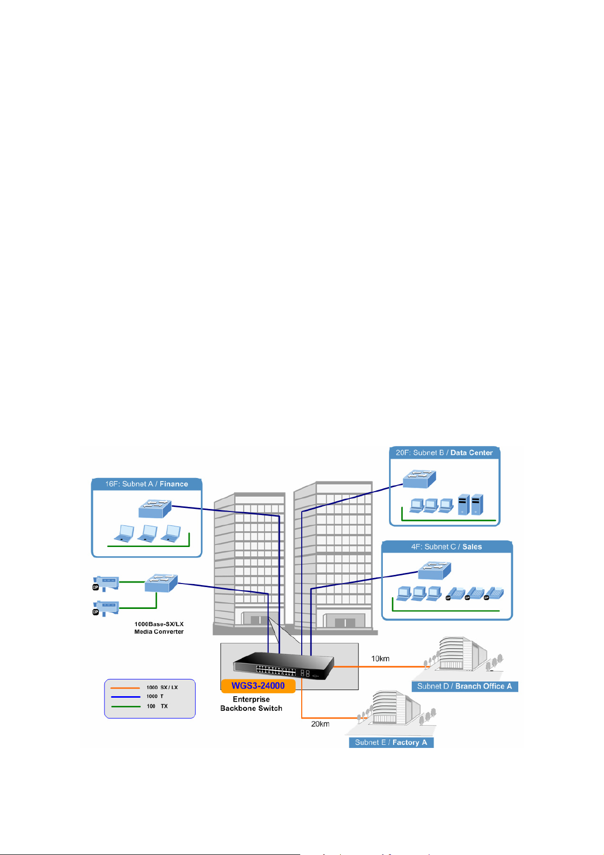
User’s Manual of WGS3-24000 / WGS3-24240
Excellent Traffic Control
The WGS3 Layer 3 Switch is loaded with powerful traffic management and QoS features to enhance services offered by
telecoms. The QoS features include wire-speed Layer 4 traffic classifiers, bandwidth limiting, Policy-Based DiffServ that are
particular helpful for multi-tenant unit, multi business unit, Telco, or Network Service Provide applications. It also empowers the
enterprises to take full advantages of the limited network resources and guarantee the best performance at VoIP and Video
conferencing transmission.
Powerful Security
The PLANET WGS3 Layet 3 Switch offers comprehensive Access Control List (ACL) to enforce security to the edge. Its
protection mechanisms comprise port-based 802.1x user and device authentication. The port-security is effective in limit the
numbers of clients pass through. The administrators can now construct highly secured corporate networks with considerably
less time and effort than before.
Efficient Management
With its built-in Web-based management, the WGS3 Layer 3 Switch offers an easy-to-use, platform-independent management
and configuration facility. The WGS3 Layer 3 Switch supports standard Simple Network Management Protocol (SNMP) and can
be managed via any standard-based management software. For text-based management, it can also be accessed via Telnet
and the console port. For secure remote management, the Switch supports SSL and SSH connection which encrypt the packet
content at each session.
Flexibility and Extension Solution
The mini-GBIC slots built in the WGS3 Layer 3 Switch are compatible with 1000Base-SX/LX and WDM SFP (Small Factor
Pluggable) fiber-optic modules. The data transmission distance can be extended from 550 meters (Multi-Mode fiber) up to
above 10/50/70/120 km (Single-Mode fiber or WDM fiber). They are well suited for application within the enterprise data center
and distribution.
Figure 1-1 WGS3 Enterprise Application
20
Page 21
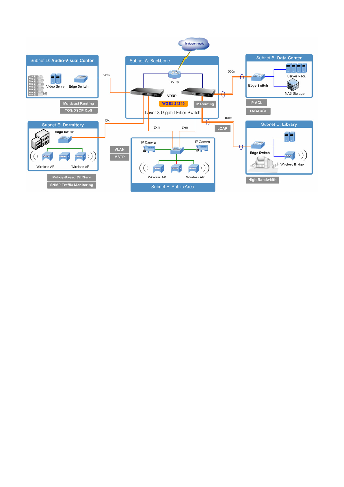
User’s Manual of WGS3-24000 / WGS3-24240
Figure 1-2 WGS3 Campus Application
1.3 How to Use This Manual
This User Manual is structured as follows:
Section 2, Installation
The section explains the functions of the Switch and how to physically install the Switch.
Section 3, SWITCH MANAGEMENT
The section contains the information about the software function of the Switch.
Section 4, Web Configuration
The section explains how to manage the switch by Web interface.
Section 5, Command Structure
The section explains how to manage the switch by Console interface.
Section 6, Quick Start Up
Section 7, Mode-Base CLI
Section 8, CLI Command:-Base
Section 9, CLI Command: Quality of Service
Section 10, CLI Command: Security
Section 11, CLI Commands: Switching
Section 12, CLI Commands: Routing
Appendex A
The section contains cable information of the Switch.
In the following section, terms with lower case "switch" means other Ethernet switch devices.
21
Page 22

User’s Manual of WGS3-24000 / WGS3-24240
1.4 Product Features
Physical Ports
WGS3-24000
24 RJ-45 ports for 10/100/1000Base-T
4 shared SFP mini-GBIC interfaces ( Shared with Port-11, Port-12, Port-23 and Port-24)
One DB9 male/RS-232 console port
WGS3-24000
24 1000Base-SX/LX SFP slots
4 shared RJ-45 for 10/100/1000Base-T ( Shared with Port-11, Port-12, Port-23 and Port-24)
One DB9 male/RS-232 console port
Layer 2 Features
Supports auto MDI/MDI-X on all 10/100/1000Base-T ports
The 10/100/1000Base-TX ports support auto-sensing, auto-negotiation
Supports Jumbo frame up to 9KB
Provides wire speed of L2 switching performance
Supports up to 16K MAC address entries
Supports Flow Control
− IEEE 802.1x for Full-Duplex mode
− Back-Pressure in Half-Duplex mode
Provides Store-and-Forward forwarding scheme
Provides Broadcast storm protection
Supports IGMP snooping v1, v2
Supports VLAN
− IEEE 802.1Q VLAN
− GARP/GVRP/GMRP
− Up to 4041 VLANs, out of 4041 VLAN IDs
− Protocol-Based VLAN
Supports Spanning Tree Protocol
− STP, IEEE 802.1d
− RSTP, IEEE 802.1w Rapid Spanning Tree
− MSTP, IEEE 802.1s Multiple Spanning Tree
Supports Link Aggregation
− up to 8 trunk groups
− up to 8 ports per trunk group
− 802.3ad Link Aggregation and LACP
− Cisco ether-channel (Static Trunk)
Provides Port Mirror (many-to-1)
22
Page 23

Routing Features
Supports RIP v1 and v2
Supports OSPF v1/v2
Supports router discovery (IRDP)
Supports VLAN routing
Supports VRRP
Supports IP routing
Supports route redistribution
Supports route preferences
Multicast
Supports PIM-DM and PIM-SM
Supports DVMRP
Supports IGMP v1/v2/v3
User’s Manual of WGS3-24000 / WGS3-24240
Security
User/Password protected system management
L2/L3/L4 ACL (access control list)
RADIUS client
TACACS client
SSH v1/v2
SSL v3/TLS v1
IEEE 802.1x Port-Based Autentication
Port MAC lock
Quality of Service
IEEE 802.1p based CoS
8 priority queues per port
IP TOS/Precedence based Cos
DSCP based CoS
Policy based DiffServ
Management
Provides 1 male DB9 RS-232C console interface
Supports BOOTP and DHCP for IP address assignment
Supports DHCP relay function
Supports software upload/download via XMODEM or TFTP
Supports configuration upload/download via XMODEM or TFTP
Supports up to three configuration files including factory default
Supports SSH v1/v2 switch management
Supports SSH/SSL/TLS keys download via XMODEM or TFTP
23
Page 24
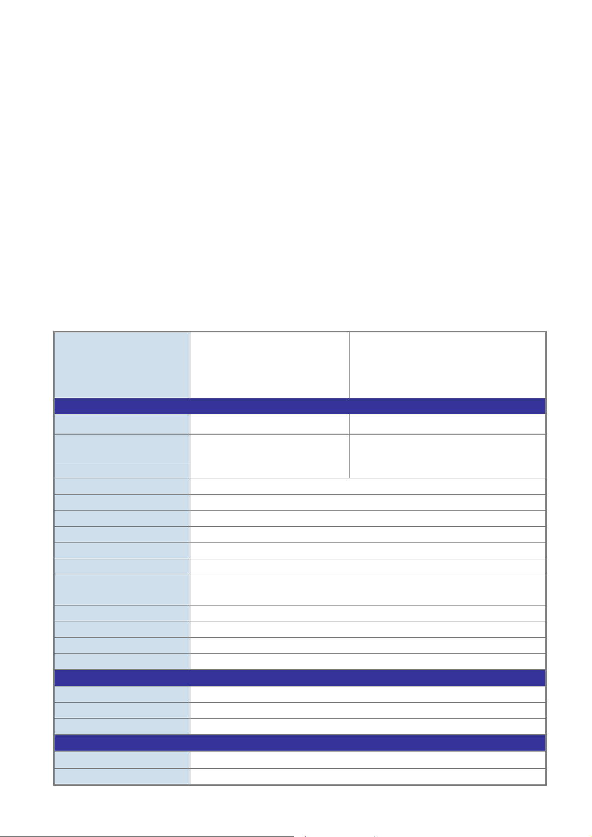
Supports SNTP (Simple Network Time Protocol)
Supports Ping function
Supports telnet function
Supports message/event/error/trap logs
Supports logging to local file and syslog server
Supports Command Line Interface switch management
Supports Web switch management
Supports SNMP v1, v2c, and v3 switch management
Supports Private Enterprise MIB
Supports RMON groups 1, 2, 3, 9
Supports port mirror (many-to-1)
1.5 Product Specification
User’s Manual of WGS3-24000 / WGS3-24240
WGS3-24000
Product
Hardware Specification
SFP/mini-GBIC slots
10/100/1000Base-T Ports
Switch Architecture Store-and-Forward
Switch Fabric 48Gbps / non-blocking
Switch Throughput 35.7Mpps
Address Table 16K MAC address table with Auto learning function
Layer 3 Routing Table 2048 entries
Buffer Memory 2Mbytes for packet buffer
Flow Control
Jumbo Frame 9Kbytes
LED Power, Link/Act, FDX/COL
Dimension 440 x 44.5 x 350mm (W x H x D), 1U height
Weight 5kg
Layer 3 function
IP Routing Protocol Static Route, RIPv1/v2, OSPFv2, IRDP, VRRP
Multicast Routing Protocol IGMP, DVMRP, PIM-DM/SM
Routing Interface Per Port / Per VLAN
Layer 2 function
Management Interface Console. Telnet, SSH, Web, SSL, SNMP
24-Port 10/100/1000Mbps TP with
4-Port mini-GBIC
Layer 3 Managed Ethernet Switch
24 RJ-45, Auto-MDI/MDI-X ports
4 SFP interfaces
Back pressure for Half-Duplex
IEEE 802.3x Pause Frame for Full-Duplex
WGS3-24240
24-Port Gigabit SFP slots with 4 shared
10/100/1000Base-T
Layer 3 Managed Fiber Switch
24 SFP interfaces, support 1000Base-SX/LX
4 RJ-45 Auto-MDI/MDI-X ports
Shared with Port-11, Port-12, Port-23 and
Port-24
Port Configuration Port disable/enable
24
Page 25
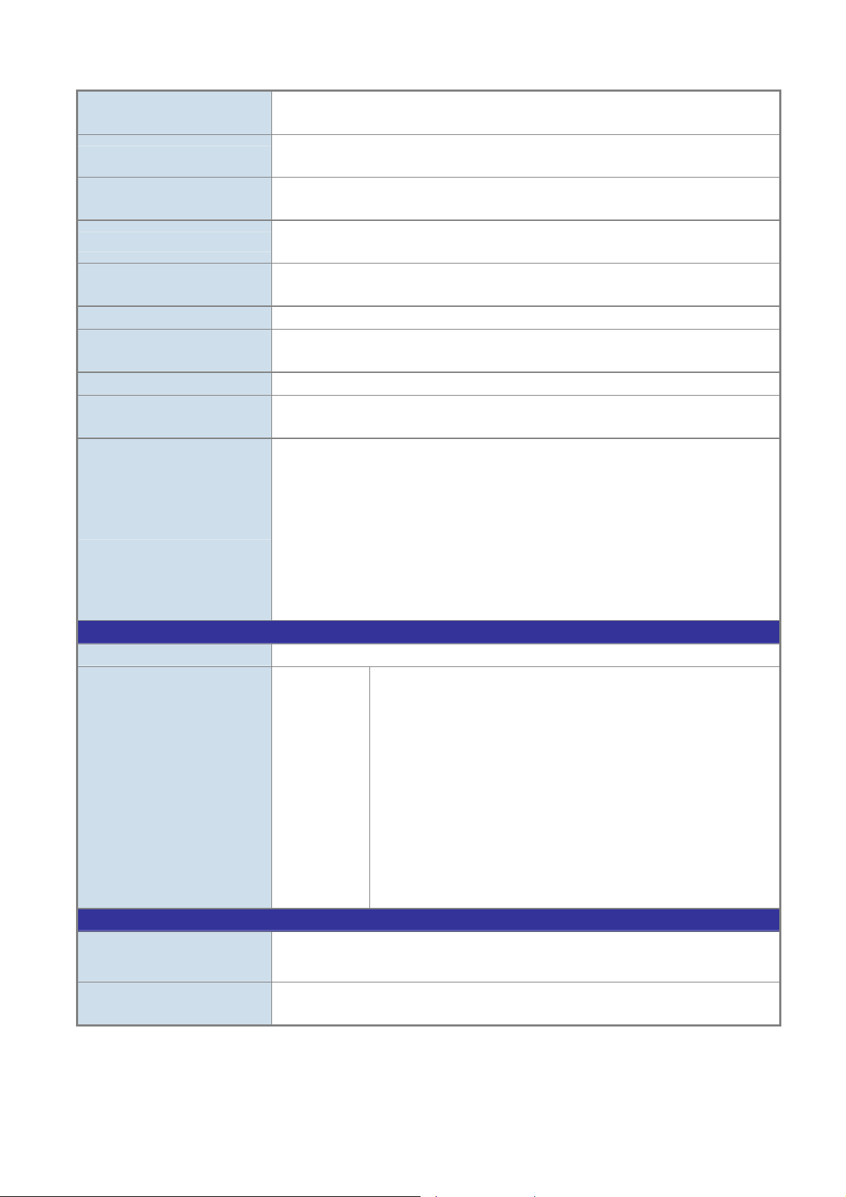
Auto-negotiation 10/100Mbps full and half duplex mode selection.
Maximum frame size
Port Status
VLAN
Link Aggregation
QoS
Bandwidth Control Egress Traffic Shaping
IGMP Snooping
Port Mirror RX / TX / Both
Access Control List
SNMP MIBs
Standards Conformance
Regulation Compliance FCC Part 15 Class A, CE
Standards Compliance
Environment
Display each port’s speed duplex mode, link status, Flow control status. Auto negotiation
status, trunk status.
IEEE 802.1Q Tagged Based VLAN ,up to 4094 VLAN groups
GVRP protocol for VLAN management.
Support 8 groups of 8-Port trunk support
IEEE 802.3ad LACP
Traffic classification based on Port Number, 802.1p priority, DS/TOS field in IP Packet
Policy-based DiffServ
Supports v1, v2 and v3.
Maximum up to 255 multicast groups.
IP-Based ACL / MAC-Based ACL
Up to 100 entries
RFC-1213 MIB-II
RFC-2863 Interface MIB
RFC-2665 EtherLike MIB
RFC-1493 Bridge MIB
RFC-2674 Extended Bridge MIB
RFC-2819 RMON MIB (Group 1, 2, 3 and 9)
RFC-2737 Entity MIB
RFC-2618 RADIUS Client MIB
PLANET Private MIB
IEEE 802.3
IEEE 802.3u
IEEE 802.3z
IEEE 802.3ab
IEEE 802.3x
IEEE 802.3ad
IEEE 802.1d
IEEE 802.1w
IEEE 802.1s
IEEE 802.1p
IEEE 802.1Q
IEEE 802.1x
User’s Manual of WGS3-24000 / WGS3-24240
10Base-T
100Base-TX
Gigabit SX/LX
Gigabit 1000T
Flow Control
Port trunk with LACP
Spanning tree protocol
Rapid Spanning tree protocol
Multiple Spanning Tree Protocol
Class of service
VLAN Tagging
Port Authentication Network Control
Operating
Storage
Temperature: 0°C ~ 50 degree C
Relative Humidity: 20% ~ 85% (non-condensing)
Temperature: -40°C ~ 70 degree C
Relative Humidity: 20% ~ 90% (non-condensing)
25
Page 26
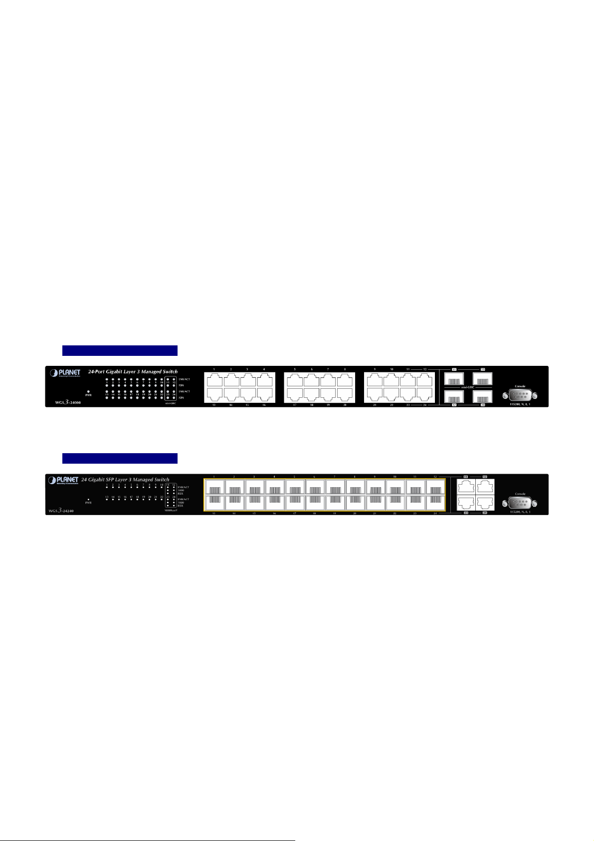
User’s Manual of WGS3-24000 / WGS3-24240
2. INSTALLATION
This section describes the hardware features and installation of the WGS3 Layer 3 Switch on the desktop or rack mount. For
easier management and control of the switch, familiarize yourself with its display indicators, and ports. Front panel illustrations
in this chapter display the unit LED indicators. Before connecting any network device to the switch, please read this chapter
completely.
2.1 Hardware Description
2.1.1 Switch Front Panel
The unit front panel provides a simple interface monitoring the switch. Figure 2-1 and 2-2 shows the front panel of the WGS3
Layer 3 Switches.
■ WGS3-24000 Front Panel
Figure 2-1 WGS3-24000 front panel.
■ WGS3-24240 Front Panel
Figure 2-2 WGS3-24240 front panel.
■ Gigabit TP interface
10/100/1000Base-T Copper, RJ-45 Twist-Pair: Up to 100 meters.
■ Gigabit SFP slots
1000Base-SX/LX mini-GBIC slot, SFP (Small Factor Pluggable) transceiver module: From 550 meters (Multi-mode fiber),
up to 10/30/50/70/120 kilometers (Single-mode fiber).
■ Console Port
The console port is a DB9, RS-232 male seria port connector. It is an interface for connecting a terminal directly. Through
the console port, it provides rich diagnostic information includes factory reset, forgotten password access, network statistics,
link status and system setting. Users can use the attached RS-232 cable in the package and connect to the console port on
the device. After the connection, users an run any terminal emulation program (Hyper Terminal, ProComm Plus, Telix,
Winterm and so on) to enter the statup screen of the device.
26
Page 27
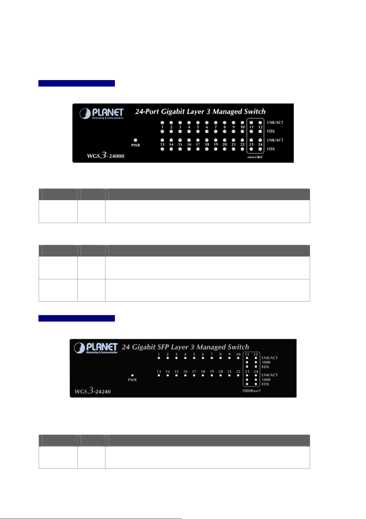
User’s Manual of WGS3-24000 / WGS3-24240
2.1.2 LED Indications
The front panel LEDs indicates instant status of port links, data activity, system operation and system power, helps monitor and
troubleshoot when needed.
■ WGS3-24000 LED indication
Figure 2-3 WGS3-24000 LED panel
■ System
LED Color Function
PWR
Green
Blink to indicate the System is running under booting procedure.
Lights to indicate that the Switch is powered on.
■ 10/100/1000Base-T interfaces (Port-1 to Por-10, Port-13 to Port-22) and Combo interfaces
LED Color Function
LNK/ACT
FDX
Green
Orange
■ WGS3-24240 LED indication
Lights to indicate the link through that port is successfully established.
Blink: indicate that the switch is actively sending or receiving data over that port.
Lights to indicate the link through that port is established at Full Duplex mode
Off to indicate the link through that port is established at Half Duplex mode
Figure 2-3 WGS3-24240 LED panel
■ System
LED Color Function
Lights to indicate that the Switch is powered on.
PWR
Green
Blink to indicate the System is running under booting procedure.
■ 1000Base-SX/LX SFP ports (Port-1 to Por-10, Port-13 to Port-22)
27
Page 28
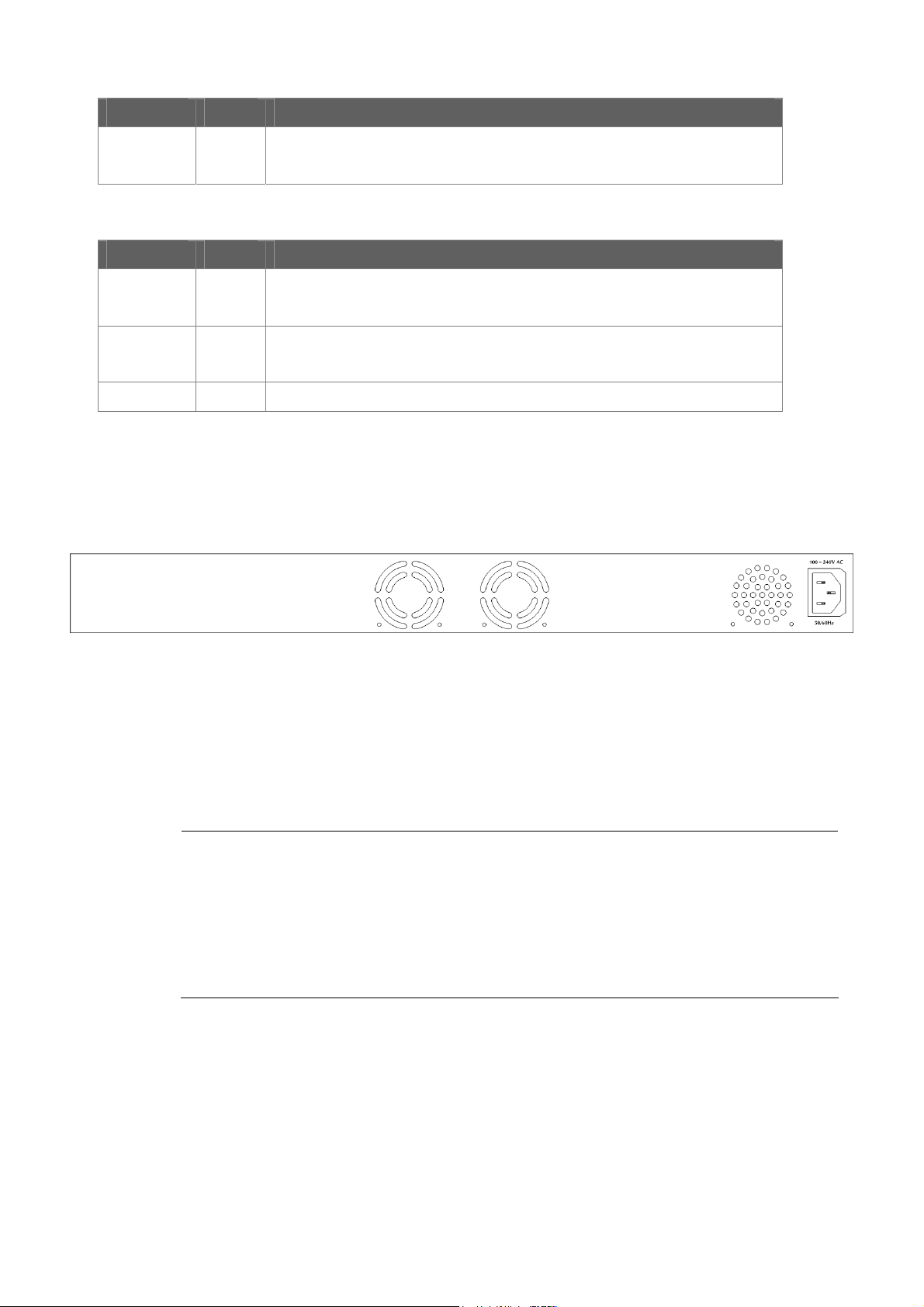
LED Color Function
User’s Manual of WGS3-24000 / WGS3-24240
LNK/ACT
■ 10/100/1000Base-T interfaces (Port-11, Port-12, Port-23 and Port-24)
Green
Lights to indicate the link through that port is successfully established.
Blink: indicate that the switch is actively sending or receiving data over that port.
LED Color Function
Lights to indicate the link through that port is successfully established.
Blink: indicate that the switch is actively sending or receiving data over that port.
Lights to indicate the port is running in 1000Mbps speed.
Off: indicate that the port is operating at 10Mbps or 100Mbps.
LNK/ACT
1000
FDX
Green
Green
Orange Lights to indicate the link through that port is established at Full Duplex mode
2.1.3 Switch Rear Panel
The rear panel of the WGS3-Layer 3 Switch indicates an AC inlet power socket, which accept input power from 100 to 240V AC,
50-60Hz. Figure 2-2 shows the rear panel of the switch
Figure 2-4 Rear panel of WGS3-24000 and WGS3-24240.
■ Power Receptacle
For compatibility with electric service in most areas of the world, the WGS3-Layer 3 Switch’s power supply automatically
adjusts to line power in the range 100-240VAC and 50/60 Hz.
Plug the female end of the power cord firmly into the receptalbe on the rear panel of the Switch. Plug the other end of the
power cord into an electric service outlet then the power will be ready.
1. The device is a power-required device, it means, it will not work till it is powered. If your networks
should active all the time, please consider using UPS (Uninterrupted Power Supply) for your device. It
will prevent you from network data loss or network downtime.
Power Notice:
2. In some area, installing a surge suppression device may also help to protect your WGS3 Layer 3
Switch from being damaged by unregulated surge or current to the Switch or the power adapter.
28
Page 29

User’s Manual of WGS3-24000 / WGS3-24240
2.2 Install the Switch
This section describes how to install your WGS3 Layer 3 Switch and make connections to the Switch. Please read the following
topics and perform the procedures in the order being presented. To install your WGS3 Layer 3 Switch on a desktop or shelf,
simply complete the following steps.
2.2.1 Desktop Installation
To install the WGS3 Layer 3 Switch on desktop or shelf, please follows these steps:
Step1: Attach the rubber feet to the recessed areas on the bottom of the WGS3 Layer 3 Switch.
Step2: Place the switch on the desktop or the shelf near an AC power source.
Step3: Keep enough ventilation space between the WGS3 Layer 3 Switch and the surrounding objects.
When choosing a location, please keep in mind the environmental restrictions discussed in Chapter
1, Section 4, and Specification.
Step4: Connect the WGS3 Layer 3 Switch to network devices.
A. Connect one end of a standard network cable to the 10/100/1000 RJ-45 ports on the front of the WGS3 Layer 3 Switch
B. Connect the other end of the cable to the network devices such as printer servers, workstations or routers…etc.
Connection to the WGS3 Layer 3 Switch requires UTP Category 5 network cabling with RJ-45 tips.
For more information, please see the Cabling Specification in Appendix A.
Step5: Supply power to the WGS3 Layer 3 Switch.
A. Connect one end of the power cable to the WGS3 Layer 3 Switch.
B. Connect the power plug of the power cable to a standard wall outlet.
When the WGS3 Layer 3 Switch receives power, the Power LED should remain solid Green.
2.2.2 Rack Mounting
To install the WGS3 Layer 3 Switch in a 19-inch standard rack, please follows the instructions described below.
Step1: Place the WGS3 Layer 3 Switch on a hard flat surface, with the front panel positioned towards the front side.
Step2: Attach the rack-mount bracket to each side of the WGS3 Layer 3 Switch with supplied screws attached to the package.
Figure 2-5 shows how to attach brackets to one side of the WGS3 Layer 3 Switch.
29
Page 30
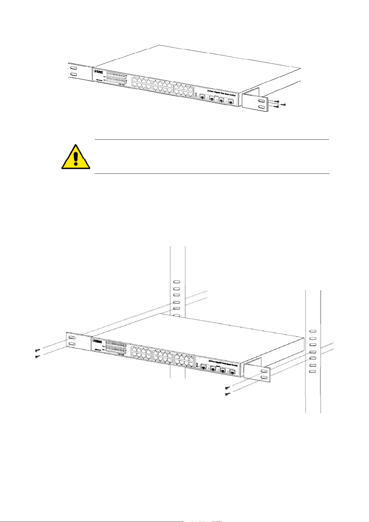
You must use the screws supplied with the mounting brackets. Damage caused to the parts by
using incorrect screws would invalidate the warranty.
Step3: Secure the brackets tightly.
User’s Manual of WGS3-24000 / WGS3-24240
Figure 2-5 Attach brackets to the WGS3 Layer 3 Switch.
Step4: Follow the same steps to attach the second bracket to the opposite side.
Step5: After the brackets are attached to the WGS3 Layer 3 Switch, use suitable screws to securely attach the brackets to the
rack, as shown in Figure 2-6
Figure 2-6 Mounting the Switch in a Rack
Step6: Proceeds with the steps 4 and steps 5 of session 2.2.1 Desktop Installation to connect the network cabling and supply
power to the WGS3 Layer 3 Switch.
30
Page 31

User’s Manual of WGS3-24000 / WGS3-24240
2.2.3 Installing the SFP transceiver
The sections describe how to insert an SFP transceiver into an SFP slot.
The SFP transceivers are hot-pluggable and hot-swappable. You can plug-in and out the transceiver to/from any SFP port
without having to power down the WGS3 Layer 3 Switch. As the Figure 2-7 appears.
Figure 2-7 Plug-in the SFP transceiver
Approved PLANET SFP Transceivers
PLANET WGS3 Layer 3 Switch supports both Single mode and Multi-mode SFP transceiver. The following list of approved
PLANET SFP transceivers is correct at the time of publication:
■MGB-SX SFP (1000BASE-SX SFP transceiver )
■MGB-LX SFP (1000BASE-LX SFP transceiver )
It recommends using PLANET SFPs on the Switch. If you insert a SFP transceiver that is not
supported, the Switch will not recognize it.
Before connect the other WGS3 Layer 3 Switches, workstation or Media Converter.
1. Make sure both side of the SFP transceiver are with the same media type, for example: 1000Base-SX to 1000Base-SX,
1000Bas-LX to 1000Base-LX.
2. Check the fiber-optic cable type match the SFP transceiver model.
¾ To connect to 1000Base-SX SFP transceiver, use the Multi-mode fiber cable- with one side must be male duplex LC
connector type.
¾ To connect to 1000Base-LX SFP transceiver, use the Single-mode fiber cable-with one side must be male duplex
LC connector type.
31
Page 32

User’s Manual of WGS3-24000 / WGS3-24240
Connect the fiber cable
1. Attach the duplex LC connector on the network cable into the SFP transceiver.
2. Connect the other end of the cable to a device – switches with SFP installed, fiber NIC on a workstation or a Media
Converter..
3. Check the LNK/ACT LED of the SFP slot on the front of the WGS3 Layer 3 Switch. Ensure that the SFP transceiver is
operating correctly.
4. Check the Link mode of the SFP port if the link failed. Co works with some fiber-NICs or Media Converters, set the Link
mode to “1000 Force” is needed.
Remove the transceiver module
1. Make sure there is no network activity by consult or check with the network administrator. Or through the
management interface of the switch/converter (if available) to disable the port in advance.
2. Remove the Fiber Optic Cable gently.
3. Turn the handle of the MGB module to horizontal.
4. Pull out the module gently through the handle.
Never pull out the module without pull the handle or the push bolts on the module. Direct pull
out the module with violent could damage the module and SFP module slot of the WGS3
Layer 3 Switch.
Figure 2-8 Pull Out the SFP transceiver
32
Page 33

User’s Manual of WGS3-24000 / WGS3-24240
3. SWITCH MANAGEMENT
This chapter explains the methods that you can use to configure management access to the switch. It describes the types of
management applications and the communication and management protocols that deliver data between your management
device (work-station or personal computer) and the system. It also contains information about port connection options.
This chapter covers the following topics:
Requirements
Management Access Overview
Key Concepts
Key Guidelines for Implementation
Administration Console Access
Web Management Access
SNMP Access
Standards, Protocols, and Related Reading
3.1 Requirements
Workstations of subscribers running Windows 98/ME, NT4.0, 2000/XP, MAC OS9 or later, Linux, UNIX or other
platform compatible with TCP/IP protocols.
Workstation installed with Ethernet NIC (Network Interface Card)
Serial Port connect (Terminal)
• Above PC with COM Port (DB-9 / RS-232) or USB-to-RS-232 converter
Ethernet Port connect
• Network cables - Use standard network (UTP) cables with RJ45 connectors.
Above Workstation installed with WEB Browser and JAVA runtime environment Plug-in
It is recommended to use Internet Explore 6.0 or above to access WGS3 Layer 3 Switch.
33
Page 34

User’s Manual of WGS3-24000 / WGS3-24240
3.2 Management Access Overview
The switch gives you the flexibility to access and manage the switch using any or all of the following methods:
▫ An administration console
▫ Web browser interface
▫ An external SNMP-based network management application
The administration console and Web browser interface support are embedded in the switch software and are available for
immediate use. Each of these management methods has their own advantages. Table 3-1 compares the three management
methods.
Method Advantages Disadvantages
Console
Web Browser
SNMP Agent
y No IP address or subnet needed
y Text-based
y Telnet functionality and HyperTerminal
built into Windows
95/98/NT/2000/ME/XP operating
systems
y Secure
y Ideal for configuring the switch remotely
y Compatible with all popular browsers
y Can be accessed from any location
y Most visually appealing
y Communicates with switch functions at
the MIB level
y Based on open standards
y Must be near switch or use dial-up connection
y Not convenient for remote users
y Modem connection may prove to be unreliable
or slow
y Security can be compromised (hackers need
only know the IP address and subnet mask)
y May encounter lag times on poor connections
y Requires SNMP manager software
y Least visually appealing of all three methods
y Some settings require calculations
y Security can be compromised (hackers need
only know the community name)
Table 3-1 Management Methods Comparison
3.3 Administration Console
The administration console is an internal, character-oriented, and command line user interface for performing system
administration such as displaying statistics or changing option settings. Using this method, you can view the administration
console from a terminal, personal computer, Apple Macintosh, or workstation connected to the switch's console (serial) port.
There are two ways to use this management method: via direct access or modem port access. The following sections describe
these methods. For more information about using the console, refer to Chapter 5 Command Line Interface Console
Management.
34
Page 35

User’s Manual of WGS3-24000 / WGS3-24240
Direct Access
Direct access to the administration console is achieved by directly connecting a terminal or a PC equipped with a
terminal-emulation program (such as HyperTerminal) to the switch console (serial) port.
When using this management method, a null-modem cable is required to connect the switch to the PC. After making this
connection, configure the terminal-emulation program to use the following parameters:
The default parameters are:
▫ 115,200 bps
▫ 8 data bits
▫ No parity
▫ 1 stop bit
You can change these settings, if desired, after you log on. This management method is often preferred because you can
remain connected and monitor the system during system reboots. Also, certain error messages are sent to the serial port,
regardless of the interface through which the associated action was initiated. A Macintosh or PC attachment can use any
terminal-emulation program for connecting to the terminal serial port. A workstation attachment under UNIX can use an
emulator such as TIP.
3.4 Web Management
The switch provides a browser interface that lets you configure and manage the switch remotely. After you set up your IP
address for the switch, you can access the switch's Web interface applications directly in your Web browser by entering the IP
address of the switch. You can then use your Web browser to list and manage switch configuration parameters from one central
location, just as if you were directly connected to the switch's console port.
Web Management requires either Microsoft Internet Explorer 6.0 or later or Mozilla Firefox 1.5 or later.
35
Page 36

User’s Manual of WGS3-24000 / WGS3-24240
3.5 SNMP-Based Network Management
You can use an external SNMP-based application to configure and manage the switch. This management method requires the
SNMP agent on the switch and the SNMP Network Management Station to use the same community string. This management
method, in fact, uses two community strings: the get community string and the set community string. If the SNMP Net-work
management Station only knows the set community string, it can read and write to the MIBs. However, if it only knows the get
community string, it can only read MIBs. The default gets and sets community strings for the switch are public.
3.6 Protocols
The switch supports the following protocols:
▫ Virtual terminal protocols, such as Telnet
▫ Simple Network Management Protocol (SNMP)
3.6.1 Virtual Terminal Protocols
A virtual terminal protocol is a software program, such as Telnet, that allows you to establish a management session from a
Macintosh, a PC, or a UNIX workstation. Because Telnet runs over TCP/IP, you must have at least one IP address configured
on the WGS3 Layer 3 Switch before you can establish access to it with a virtual terminal protocol.
Terminal emulation differs from a virtual terminal protocol in that you must connect a terminal directly
to the console (serial) port.
3.6.2 SNMP Protocol
Simple Network Management Protocol (SNMP) is the standard management protocol for multi-vendor IP networks. SNMP
supports transaction-based queries that allow the protocol to format messages and to transmit information between reporting
devices and data-collection programs. SNMP runs on top of the User Datagram Protocol (UDP), offering a
connectionless-mode service.
3.6.3 Management Architecture
All of the management application modules use the same Messaging Application Programming Interface (MAPI). By unifying
management methods with a single MAPI, configuration parameters set using one method (console port, for example) are
immediately displayable by the other management methods (for example, SNMP agent of Web browser).
The management architecture of the switch adheres to the IEEE open standard. This compliance assures customers that the
WGS3 Layer 3 Switch is compatible with, and will interoperate with other solutions that adhere to the same open standard.
36
Page 37

User’s Manual of WGS3-24000 / WGS3-24240
4. WEB CONFIGURATION
This section introduces the configuration and functions of the Web-Based management.
About Web-based Management
The WGS3 Layer 3 Switch offers management features that allow users to manage the WGS3 Layer 3 Switch from anywhere
on the network through a standard browser such as Microsoft Internet Explorer.
The Web-Based Management supports Internet Explorer 6.0. It is based on Java Applets with an aim to reduce network
bandwidth consumption, enhance access speed and present an easy viewing screen.
By default, IE6.0 or later version does not allow Java Applets to open sockets. The user has to
explicitly modify the browser setting to enable Java Applets to use network ports.
The WGS3 Layer 3 Switch can be configured through an Ethernet connection, make sure the manager PC must be set on same
the IP subnet address with the WGS3 Layer 3 Switch.
For example, if you have changed the default IP address of the Switch to 192.168.1.1 with subnet mask 255.255.255.0 via
console, then the manager PC should be set at 192.168.1.x (where x is a number between 2 and 253) with subnet mask
255.255.255.0. Or you can use the factory default IP address 192.168.1.254 to do the relative configuration on manager PC.
Logging on the switch
1. Use Internet Explorer 6.0 or above Web browser. Enter the factory-default IP address to access the Web interface. The
factory-default IP Address as following:
http://192.168.1.254
2. When the following login screen appears, the system will ask you to enter the username and password.
Default User name: admin
Default Password: admin
37
Page 38

The login screen in Figure 4-1-1 appears.
User’s Manual of WGS3-24000 / WGS3-24240
Figure 4-1-1 WGS3 Login screen
3. When the following login screen appears, please enter the default username "admin" with password “admin” (or the
username/password you have changed via console) to login the main screen of WGS3 Layer 3 Switch. The login screen
in Figure 4-1-2 appears.
Figure 4-1-2 Login screen
After entering the username and password, the main screen appears as Figure 4-1-3.
38
Page 39

User’s Manual of WGS3-24000 / WGS3-24240
Figure 4-1-3 Default main page
Now, you can use the Web management interface to continue the switch management or manage the WGS3 Layer 3 Switch by
Web interface.
1. It is recommended to use Internet Explore 6.0 or above to access WGS3 Layer 3 Switch.
2. The changed IP address take effect immediately after click on the OK button, you need to
use the new IP address to access the Web interface.
3. The changed IP address remains the original after reboot the switch unless the
configuration is saved. To save the changed IP address, please move to System \ System
Utility \ Saving Parameters menu.
39
Page 40

User’s Manual of WGS3-24000 / WGS3-24240
4.1 Main Menu
The WGS3 Layer 3 Switch provides a Web-based browser interface for configuring and managing the WGS3 Layer 3 Switch.
This interface allows you to access the WGS3 Layer 3 Switch using the Web browser of your choice. This chapter describes
how to use the WGS3 Layer 3 Switch’s Web browser interface to con-figure and manage the WGS3 Layer 3 Switch.
Main Functions Menu
Port Link Status
Main Screen
Help Button
Figure 4-1-4 Main Page
Via the Web-Management, the administrator can setup the WGS3 Layer 3 Switch by select the functions those listed in the Main
Function. The screen in Figure 4-1-5 appears.
Figure 4-1-5 WGS3 Layer 3 Switch Main Funcrions Menu
Apply Button
40
Page 41

User’s Manual of WGS3-24000 / WGS3-24240
The following functions can be configured here:
System
Switching
Routing
Security
QoS
IP Multicast
System Description
After a successful login, the main screen appears, the main screen displays the port status and a list of System section and the
topics it provide. As showed in Figure 4-1-6.
。 System Name - Enter the name you want to use to identify this switch. You may use up to 31 alpha-numeric
characters. The factory default is blank.
。 System Location - Enter the location of this switch. You may use up to 31 alpha-numeric characters. The factory
default is blank.
。 System Contact - Enter the contact person for this switch. You may use up to 31 alpha-numeric characters. The
factory default is blank.
Figure 4-1-6 main menu screen
41
Page 42

User’s Manual of WGS3-24000 / WGS3-24240
4.2 Configure System
The System section provides information for configuring system parameters. Under system the following topics are provided to
configure and view the system information:
。 ARP Cache
。 Inventory Information
。 System Loading
。 Configuration
。 Forward Database
。 Log
。 Port
。 SNMP
。 Statistics
。 System Utilities
。 Trap Manager
。 DHCP Server
。 SNTP
4.2.1 ARP Cache
The Address Resolution Protocol (ARP) dynamically maps physical (MAC) addresses to Internet (IP) addresses. This panel
displays the current contents of the ARP cache.
For each connection, the following information is displayed:
。 The physical (MAC) Address
。 The associated IP address
。 The identification of the port being used for the connection
As shows in Figure 4-2-1:
Figure 4-2-1 ARP Cache
42
Page 43

User’s Manual of WGS3-24000 / WGS3-24240
4.2.2 Inventory Information
Use this panel to display the WGS3 Layer 3 Switch's Vital Product Data, stored in non-volatile memory at the factory. The page
includes the following fields:
Object Description
• System Description -
• Machine Type -
• Machine Model -
• Serial Number -
• FRU Number -
• Part Number -
• Maintenance Level -
• Manufacturer -
• Base MAC Address -
• Software Version -
• Operating System -
The product name of this WGS3 Layer 3 Switch.
The machine type of this WGS3 Layer 3 Switch.
The model within the machine type.
The unique box serial number for this WGS3 Layer 3 Switch
The field replaceable unit number.
The manufacturing part number.
The identification of the hardware change level.
The two-octet code that identifies the manufacturer.
The burned-in universally administered MAC address of this WGS3 Layer 3
Switch.
The release version maintenance number of the code currently running on the
WGS3 Layer 3 Switch. For example, if the release was 1, the version was 2 and
the maintenance number was 4, the format would be '1.2.4'.
The operating system currently running on the WGS3 Layer 3 Switch
Figure 4-2-2 Inventory Information
43
Page 44

User’s Manual of WGS3-24000 / WGS3-24240
4.2.3 Configuration
Use this page to configure the parameters for system management, including the following fields:
。 System Description
。 Switch
。 Network Connectivity
。 Telnet Session
。 Outbound Telnet Client Configuration
。 Serial Port
。 User Account
。 Authentication List Configuration
。 Login Session
。 Authentication List Summary
。 User Login
4.2.3.1 System Description
This page shows the basic system information and is available to define the system name, location and contact person.
Figure 4—2-3 System Description
The page includes the following fields:
Object Description
• System Name -
• System Location -
Enter the name you want to use to identify this switch. You may use up to 31
alpha-numeric characters.
The factory default is blank.
Enter the location of this switch. You may use up to 31 alpha-numeric characters.
The factory default is blank.
44
Page 45

User’s Manual of WGS3-24000 / WGS3-24240
• System Contact -
Enter the contact person for this switch. You may use up to 31 alpha-numeric
characters.
The factory default is blank.
• System Description -
• System Object ID -
• System IP Address -
• System Up time -
• MIBs Supported-
The product name of this WGS3 Layer 3 Switch.
The base object ID for the WGS3 Layer 3 Switch's enterprise MIB.
The IP Address assigned to the network interface.
The time in days, hours and minutes since the last switch reboot.
- The list of MIBs supported by the management agent running on this WGS3
Layer 3 Switch.
4.2.4.2 Switch Configuration
Choose Switch Configuration from “Configuration” of WGS3 Layer 3 Switch, the screen in Figure 4-2-4 appears.
This page includes the following fields:
Object Description
• Broadcast Storm
Recovery Mode -
• IEEE 802.3x Flow
Control Mode
• Lag Static Capability
Mode
Figure 4-2-4 Switch Configuration
Enable or disable this option by selecting the corresponding line on the pull-down
entry field. The factory default is disabled.
Enable or disable this option by selecting the corresponding line on the pull-down
entry field. The factory default is disabled.
May be enabled or disabled by selecting the corresponding line on the pull-down
entry field. The factory default is disabled.
45
Page 46

User’s Manual of WGS3-24000 / WGS3-24240
4.2.3.3 Network Connectivity
The network interface is the logical interface used for in-band connectivity with the WGS3 Layer 3 Switch via any of its front
panel ports. The configuration parameters associated with the switch's network interface do not affect the configuration of the
front panel ports through which traffic is switched or routed.
Figure 4-2-5 Network Connectivity Configuration
To access the WGS3 Layer 3 Switch over a network you must first configure it with IP information (IP address, subnet mask,
and default gateway). You can configure the IP information using any of the following:
。 BOOTP
。 DHCP
。 Terminal interface via the EIA-232 port
Once you have established in-band connectivity, you can change the IP information using any of the following:
。 Terminal interface via the EIA-232 port
。 Terminal interface via telnet
。 SNMP-based management
。 Web-based management
The page includes the following configurable data:
Object Description
• IP Address
• Subnet Mask
The IP address of the interface.
The factory default value is 192.168.1.254
The IP subnet mask for the interface.
The factory default value is 255.255.255.0
46
Page 47

User’s Manual of WGS3-24000 / WGS3-24240
• Default Gateway
The default gateway for the IP interface.
The factory default value is 0.0.0.0
• Locally Administered
MAC Address
• MAC Address type
• Network Configuration
Protocol Current
• Management VLAN ID
You may configure a locally administered MAC address for in-band connectivity
instead of using the burned-in universally administered MAC address. In addition
to entering an address in this field, you must also set the MAC address type to
locally administered. Enter the address as twelve hexadecimal digits (6 bytes)
with a colon between each byte. Bit 1 of byte 0 must be set to a 1 and bit 0 to a 0,
i.e. byte 0 must have a value between x'40' and x'7F'.
Specify whether the burned-in or the locally administered MAC address should
be used for in-band connectivity.
The factory default is to use the burned-in MAC address
Choose what the switch should do following power-up: transmit a Bootp request,
transmit a DHCP request, or do nothing (none).
The factory default is DHCP.
Specifies the management VLAN ID of the switch. It may be configured to any
value in the range of 1 - 4093. The management VLAN is used for management
of the switch. This field is configurable for administrative users and read-only for
other users.
• Web Mode
• Java Mode
The following data are non-configurable:
Object Description
• Burned-in MAC
Address
• Network Configuration
Protocol Current
Specify whether the switch may be accessed from a web browser. If you choose
to enable web mode you will be able to manage the switch from a web browser.
The factory default is enabled.
Enable or disable the java applet that displays a picture of the switch at the top
right of the screen. If you run the applet you will be able to click on the picture of
the switch to select configuration screens instead of using the navigation tree at
the left side of the screen.
The factory default is disabled.
The burned-in MAC address used for in-band connectivity if you choose not to
configure a locally administered address.
Indicates what network protocol was used on the last, or current power-up cycle,
if any.
47
Page 48

4.2.3.4 Telnet Session
This page includes the following fields:
Configurable Data
User’s Manual of WGS3-24000 / WGS3-24240
Figure 4-2-6 Telnet Session Configuration
Object Description
• Telnet Session
Timeout (minutes)
• Maximum Number of
Telnet Sessions
• Allow New Telnet
Sessions
Specify how many minutes of inactivity should occur on a telnet session before
the session is logged off. You may enter any number from 1 to 160.
The factory default is 5.
Use the pulldown menu to select how many simultaneous telnet sessions will be
allowed. The maximum is 5, which is also the factory default.
If you set this to no, new telnet sessions will not be allowed.
The factory default is Yes.
4.2.3.5 Outbound Telnet Client Configuration
This page includes the following fields:
Figure 4-2-7 OutboundTelnet Client Configuration
48
Page 49

Configurable Data
Object Description
User’s Manual of WGS3-24000 / WGS3-24240
• Admin Mode
• Maximum Sessions
• Session Timeout
Specifies if the Outbound Telnet service is Enabled or Disabled.
Default value is Enabled.
Specifies the maximum number of Outbound Telnet Sessions allowed.
Default value is 5. Valid Range is (0 to 5).
Specifies the Outbound Telnet login inactivity timeout.
Default value is 5. Valid Range is (1 to 160).
4.2.3.6 Serial Port
Use this page to define the parameters of console connectivity.
The configurable data are:
Object Description
• Serial Port Login
Timeout (minutes)
• Baud Rate (bps)
And the non-configurable data:
Figure 4-2-8 Serial Port Configuration
Specify how many minutes of inactivity should occur on a serial port connection
before the switch closes the connection.
Enter a number between 0 and 160: the factory default is 5. Entering 0 disables
the timeout.
Select the default baud rate for the serial port connection from the pull-down
menu. You may choose from 1200, 2400, 4800, 9600, 19200, 38400, 57600, and
115200 baud.
The factory default is 115200 baud.
49
Page 50

User’s Manual of WGS3-24000 / WGS3-24240
Object Description
• Character Size (bits)
• Flow Control
• Parity
• Stop Bits
The number of bits in a character. This is always 8.
Whether hardware flow control is enabled or disabled. It is always disabled.
The parity method used on the serial port. It is always None.
The number of stop bits per character. The value is always 1.
50
Page 51

User’s Manual of WGS3-24000 / WGS3-24240
4.2.3.7 User Accounts
By default, two user accounts exist:
。 admin, with 'Read/Write' privileges
。 guest, with 'Read Only' privileges
By default, both of these accounts have blank passwords. The names are not case sensitive.
If you logon with a user account with 'Read/Write' privileges (i.e. as admin) you can use the User Accounts screen to assign
passwords and set security parameters for the default accounts, and to add and delete accounts (other than admin) up to the
maximum of six. Only a user with 'Read/Write' privileges may alter data on this screen, and only one account may be created
with 'Read/Write' privileges.
Selection Criteria
Object Description
• User Name Selector
Configurable Data
Object Description
Figure 4-2-9 User Accounts
You can use this screen to reconfigure an existing account, or to create a new
one. Use this pull-down menu to select one of the existing accounts, or select
'Create' to add a new one, provided the maximum of five 'Read Only' accounts
has not been reached.
51
Page 52

User’s Manual of WGS3-24000 / WGS3-24240
• User Name
Enter the name you want to give to the new account. (You can only enter data in
this field when you are creating a new account.) User names are up to eight
characters in length and are not case sensitive. Valid characters include all the
alphanumeric characters as well as the dash ('-') and underscore ('_') characters.
• Password
• Confirm Password
• Authentication
Protocol
• Encryption Protocol
• Encryption Key
Enter the optional new or changed password for the account. It will not display as
it is typed, only asterisks(*) will show. Passwords are up to eight alpha numeric
characters in length, and are case sensitive.
Enter the password again, to confirm that you entered it correctly. This field will
not display, but will show asterisks (*)
Specify the SNMPv3 Authentication Protocol setting for the selected user
account. The valid Authentication Protocols are None, MD5 or SHA. If you select
None, the user will be unable to access the SNMP data from an SNMP browser.
If you select MD5 or SHA, the user login password will be used as the SNMPv3
authentication password, and you must therefore specify a password, and it must
be eight characters long.
Specify the SNMPv3 Encryption Protocol setting for the selected user account.
The valid Encryption Protocols are None or DES. If you select the DES Protocol
you must enter a key in the Encryption Key field. If None is specified for the
Protocol, the Encryption Key is ignored.
If you selected DES in the Encryption Protocol field enter the SNMPv3
Non-Configurable Data
Object Description
• Access Mode
• SNMP v3 Access Mode
Encryption Key here. Otherwise this field is ignored. Valid keys are 0 to 15
characters long. The Apply checkbox must be checked in order to change the
Encryption Protocol and Encryption Key.
Indicates the user's access mode. The admin account always has 'Read/Write'
access, and all other accounts have 'Read Only' access.
Indicates the SNMPv3 access privileges for the user account. The admin
account always has 'Read/Write' access, and all other accounts have 'Read Only'
access.
52
Page 53

User’s Manual of WGS3-24000 / WGS3-24240
4.2.3.8 Authentication List Configuration
Use this screen to configure login lists. A login list specifies the authentication method(s) you want used to validate switch or
port access for the users associated with the list. The pre-configured users, admin and guest, are assigned to a pre-configured
list named defaultList, which you may not delete. All newly created users are also assigned to the defaultList until you
specifically assign them to a different list
Selection Criteria
Figure 4-2-10 Authentication List Configuration – Create User
Figure 4-2-11 Authentication List Configuration – DefaultList
Object Description
• Authentication List
Configurable Data
Object Description
Select the authentication login list you want to configure. Select 'create' to define
a new login list. When you create a new login list, 'local' is set as the initial
authentication method.
53
Page 54

User’s Manual of WGS3-24000 / WGS3-24240
• Authentication List
If you are creating a new login list, enter the name you want to assign. It can be
Name
• Method 1
• Method 2
up to 15 alphanumeric characters long and is not case sensitive.
Use the dropdown menu to select the method that should appear first in the
selected authentication login list. If you select a method that does not time out as
the first method, such as 'local' no other method will be tried, even if you have
specified more than one method. Note that this parameter will not appear when
you first create a new login list. The options are:
• Local- the user's locally stored ID and password will be used for
authentication
• Radius- the user's ID and password will be authenticated using the RADIUS
server instead of locally
• Reject- the user is never authenticated
• Undefined- the authentication method is unspecified (this may not be
assigned as the first method)
Use the dropdown menu to select the method, if any, that should appear second
in the selected authentication login list. This is the method that will be used if the
first method times out. If you select a method that does not time out as the
second method, the third method will not be tried. Note that this parameter will
not appear when you first create a new login list.
• Method 3
Use the dropdown menu to select the method, if any, that should appear third in
the selected authentication login list. Note that this parameter will not appear
when you first create a new login list.
4.2.3.9 Login Session
This page shows the information of login session, including:
Non-Configurable Data
Figure 4-2-12 Login Sessions
54
Page 55

User’s Manual of WGS3-24000 / WGS3-24240
Object Description
• ID
• User Name
• Connection From
• Idle Time
• Session Time
Identifies the ID of this row.
Shows the user name of user made the session.
Shows the user is connected from which machine.
Shows the idle session time.
Shows the total session time.
4.2.3.10 Authentication List Summary
This page lists the authenticate user, the information fields include:
Non-Configurable Data
Object Description
• Authentication List
• Method List
• Login Users
• 802.1x Port Security
Users
Figure 4-2-13 Authentication List Summary
Identifies the authentication login list summarized in this row.
The ordered list of methods configured for this login list.
The users you assigned to this login list on the User Login Configuration screen.
This list is used to authenticate the users for system login access.
The users you assigned to this login list on the Port Access Control User Login
Configuration screen - This list is used to authenticate the users for port access,
using the IEEE 802.1x protocol.
55
Page 56

User’s Manual of WGS3-24000 / WGS3-24240
4.2.3.11 User Login
Each configured user is assigned to a login list that specifies how the user should be authenticated when attempting to access
the switch or a port on the switch. After creating a new user account on the User Account screen, you should assign that user to
a login list for the switch using this screen and, if necessary, to a login list for the ports using the Port Access Control User Login
Configuration screen. If you need to create a new login list for the user, you would do so on the Login Configuration screen.
The pre-configured users, admin and guest, are assigned to a pre-configured list named defaultList, which you may not delete.
All newly created users are also assigned to the defaultList until you specifically assign them to a different list.
A user that does not have an account configured on the switch is termed the 'default' or 'non-configured' user. If you assign
the 'non-configured user' to a login list that specifies authentication via the RADIUS server, you will not need to create an
account for all users on each switch. However, by default the 'non-configured user' is assigned to 'defaultList', which by
default uses local authentication.
Selection Criteria
Object Description
• User
Configurable Data
Object Description
Figure 4-2-14 User Login Configuration
Select the user you want to assign to a login list. Note that you must always
associate the admin user with the default list. This forces the admin user to
always be authenticated locally to prevent full lockout from switch configuration.
If you assign a user to a login list that requires remote authentication, the user's
access to the switch from all CLI, web, and telnet sessions will be blocked until
the authentication is complete. Refer to the discussion of maximum delay in the
RADIUS configuration help.
• Authentication List
Select the authentication login list you want to assign to the user for system login.
56
Page 57

User’s Manual of WGS3-24000 / WGS3-24240
4.2.4 Forwarding Database
4.2.4.1 Configuration
Use this panel to set the Address Ageing Timeout for the forwarding database.
Figure 4-2-15 Forwarding Database
Configurable Data
Object Description
• Address Ageing
Timeout (seconds)
The forwarding database contains static entries, which are never aged out, and
dynamically learned entries, which are removed if they are not updated within a
given time. You specify that time by entering a value for the Address Ageing
Timeout. You may enter any number of seconds between 10 and 1000000.
IEEE 802.1D recommends a default of 300 seconds, which is the factory default.
4.2.4.2 Search
Use this panel to display information about entries in the forwarding database. These entries are used by the transparent
bridging function to determine how to forward a received frame.
Configurable Data
Object Description
• Filter
Specify the entries you want displayed.
• Learned: If you choose "learned" only MAC addresses that have been
learned will be displayed.
57
Page 58

User’s Manual of WGS3-24000 / WGS3-24240
• All: If you choose "all" the whole table will be displayed.
• MAC Address Search
You may also search for an individual MAC address. Enter the two byte
hexadecimal VLAN ID followed by the six byte hexadecimal MAC address in
two-digit groups separated by colons, for example 00:23:45:67:89:AB:CD:EF
where 00:23 is the VLAN ID and 45:67:89:AB:CD:EF is the MAC address. Then
click on the search button. If the address exists, that entry will be displayed as the
first entry followed by the remaining (greater) MAC addresses. An exact match is
required.
Figure 4-2-16 Forwarding Database Search
58
Page 59

User’s Manual of WGS3-24000 / WGS3-24240
4.2.5 Log
The Log enable viewing device events in real time, and recording the events for later usage. System Logs record and manage
events and report errors or informational messages
。 Buffered Log Configuration
。 Buffered Log
。 Command Logger Configuration
。 Console Log Configuration
。 Event Log
。 Hosts Configuration
。 Persistent Log Configuration
。 Persistent Log
。 Syslog Configuration
4.2.5.1 Buffered Log Configuration
This log stores messages in memory based upon the settings for message component and severity. On stackable systems, this
log exists only on the top of stack platform. Other platforms in the stack forward their messages to the top of stack log.
Figure 4-2-17 Buffered Log Configuration
Configurable Data
Object Description
• Admin Status
A log that is "Disabled" shall not log messages. A log that is "Enabled" shall log
messages. Enable or Disable logging by selecting the corresponding line on the
pulldown entry field.
• Behavior
Indicates the behavior of the log when it is full. It can either wrap around or stop
when the log space is filled.
59
Page 60

User’s Manual of WGS3-24000 / WGS3-24240
4.2.5.2 Buffered Log
This help message applies to the format of all logged messages which are displayed for the buffered log, persistent log or
console log.
Figure 4-2-18 Buffered Logs
Format of the messages
Messgges logged to a collector or relay via syslog have an identical format of either type
。 <15>Aug 24 05:34:05 STK0 MSTP[2110]: mspt_api.c(318) 237 %% Interface 12 transitioned to root state on
message age timer expiry
-The above example indicates a message with severity 7(15 mod 8) (debug) on a system that is not stack and
generated by component MSTP running in thread id 2110 on Aug 24 05:34:05 by line 318 of file mstp_api.c. This is
the 237th message logged.
Object Description
• Refresh
Refresh the page with the latest log entries.
4.2.5.3 Command Logger Configuration
This page includes the following fields:
Configurable Data
Object Description
• Admin Mode
Enable/Disable the operation of the CLI Command logging by selecting the
corresponding pulldown field and clicking Submit.
60
Page 61

Figure 4-2-19 Command Logger Configuration
4.2.5.4 Console Log Configuration
This allows logging to any serial device attached to the host.
User’s Manual of WGS3-24000 / WGS3-24240
Configurable Data
Object Description
• Admin Status
• Severity Filter
Figure 4-2-20 Console Log Configuration
A log that is "Disabled" shall not log messages. A log that is "Enabled" shall log
messages. Enable or Disable logging by selecting the corresponding line on the
pulldown entry field.
A log records messages equal to or above a configured severity threshold. Select
the severity option by selecting the corresponding line on the pulldown entry field.
These severity levels have been enumerated below:
-Emergency (0): system is unusable
-Alert (1): action must be taken immediately
-Critical (2): critical conditions
-Error (3): error conditions
-Warning (4): warning conditions
-Notice(5): normal but significant conditions
-Informational(6): informational messages
-Debug(7): debug-level messages
61
Page 62

4.2.5.5 Event Log
This allows logging to any serial device attached to the host.
Figure 4-2-21 Event Log
Configurable Data
Object Description
User’s Manual of WGS3-24000 / WGS3-24240
• Admin Status -
• Severity Filter -
A log that is "Disabled" shall not log messages. A log that is "Enabled" shall log
messages. Enable or Disable logging by selecting the corresponding line on the
pulldown entry field.
A log records messages equal to or above a configured severity threshold. Select
the severity option by selecting the corresponding line on the pulldown entry field.
These severity levels have been enumerated below:
-Emergency (0): system is unusable
-Alert (1): action must be taken immediately
-Critical (2): critical conditions
-Error (3): error conditions
-Warning (4): warning conditions
-Notice(5): normal but significant conditions
-Informational(6): informational messages
-Debug(7): debug-level messages
4.2.5.6 Hosts Configuration
Figure 4-2-22 Host Configuration
62
Page 63

Configurable Data
Object Description
User’s Manual of WGS3-24000 / WGS3-24240
• Host
• IP Address
• Port
• Severity Filter
This is a list of the hosts that have been configured for syslog. Select a host for
changing the configuration or choose to add a new hosts from the drop down list.
This is the ip address of the host configured for syslog.
This is the port on the host to which syslog messages are sent. The default port
is 514. The default port is 514. Specify the port in the text field.
A log records messages equal to or above a configured severity threshold. Select
the severity option by selecting the corresponding line on the pulldown entry field.
These severity levels have been enumerated below:
-Emergency (0): system is unusable
-Alert (1): action must be taken immediately
-Critical (2): critical conditions
-Error (3): error conditions
-Warning (4): warning conditions
-Notice(5): normal but significant conditions
-Informational(6): informational messages
-Debug(7): debug-level messages
Non Configurable Data
Object Description
• Status
• Submit button
• Refresh button
• Delete button
This specifies wether the host has been configured to be actively logging or not.
Update the switch with the values you entered.
Refetch the database and display it again starting with the first entry in the table.
Delete a configured host.
4.2.5.7 Persistent Log Configuration
A persistent log is a log that is stored in persistent storage. Persistent storage survives across platform reboots. The first log
type is the system startup log. The system startup log stores the first N messages received after system reboot. The second log
type is the system operation log. The system operation log stores the last N messages received during system operation.
63
Page 64

Configurable Data
Object Description
User’s Manual of WGS3-24000 / WGS3-24240
Figure 4-2-23 Persistent Log Configuration
• Admin Status
• Severity Filter
• Submit
A log that is "Disabled" shall not log messages. A log that is "Enabled" shall log
messages. Enable or Disable logging by selecting the corresponding line on the
pulldown entry field.
A log records messages equal to or above a configured severity threshold. Select
the severity option by selecting the corresponding line on the pulldown entry field.
These severity levels have been enumerated below:
-Emergency (0): system is unusable
-Alert (1): action must be taken immediately
-Critical (2): critical conditions
-Error (3): error conditions
-Warning (4): warning conditions
-Notice(5): normal but significant conditions
-Informational(6): informational messages
-Debug(7): debug-level messages
Update the switch with the values you entered.
4.2.5.8 Persistent Log
This help message applies to the format of all logged messages which are displayed for the buffered log, persistent log or
console log.
Figure 4-2-24 Persistent Logs
64
Page 65

User’s Manual of WGS3-24000 / WGS3-24240
Format of the messages
。 <15>Aug 24 05:34:05 STK0 MSTP[2110]: mspt_api.c(318) 237 %% Interface 12 transitioned to root state on
message age timer expiry
-The above example indicates a user-level message (1) with severity 7 (debug) on a system that is not stack and
generated by component MSTP running in thread id 2110 on Aug 24 05:34:05 by line 318 of file mstp_api.c. This
is the 237th message logged. Messages logged to a collector or relay via syslog have an identical format to the
above message.
Object Description
• Refresh button
4.2.5.9 Syslog Configuration
Configurable Data
Object Description
Refresh the page with the latest log entries.
Figure 4-2-25 Syslog Configuration
• Admin Status
• Local UDP Port
• Submit button
• Refresh button
For Enabling and Disabling logging to configured syslog hosts. Setting this to
disable stops logging to all syslog hosts. Disable means no messages will be
sent to any collector/relay. Enable means messages will be sent to configured
collector/relays using the values configured for each collector/relay.
Enable/Disable the operation of the syslog function by selecting the
corresponding line on the pulldown entry field.
This is the port on the local host from which syslog messages are sent. The
default port is XXX. The default port is 514. Specify the local port in the text field.
Update the switch with the values you entered.
Refetch the database and display it again starting with the first entry in the table.
65
Page 66

Non-Configurable Data
Object Description
User’s Manual of WGS3-24000 / WGS3-24240
• Messages Relayed
• Messages Ignored
The count of syslog messages relayed.
The count of syslog messages ignored.
4.2.6 Port
4.2.7.1 Configuration
Use this page to configure the parameters of the distinct port.
Selection Criteria
Object Description
• Slot.Port
Configurable Data
Object Description
• STP Mode
Figure 4-2-26 Port Configuration
Selects the interface for which data is to be displayed or configured.
The Select the Spanning Tree Protocol Administrative Mode for the port or LAG.
The possible values are:
66
Page 67

User’s Manual of WGS3-24000 / WGS3-24240
• Enable - select this to enable the Spanning Tree Protocol for this port.
• Disable - select this to disable the Spanning Tree Protocol for this port.
• Admin Mode
• LACP Mode
• Physical Mode
• Link Trap
• Maximum Frame Size
Use the pull-down menu to select the Port control administration state. You must
select enable if you want the port to participate in the network.
The factory default is enabled.
Selects the Link Aggregation Control Protocol administration state. The mode
must be enabled in order for the port to participate in Link Aggregation. May be
enabled or disabled by selecting the corresponding line on the pull-down entry
field. The factory default is enabled.
Use the pull-down menu to select the port's speed and duplex mode. If you select
auto the duplex mode and speed will be set by the auto-negotiation process.
Note that the port's maximum capability (full duplex and 100 Mbps) will be
advertised. Otherwise, your selection will determine the port's duplex mode and
transmission rate. The factory default is auto. The selection when applied against
the "All" option in Slot.Port is applied to all applicable interfaces only.
This object determines whether or not to send a trap when link status changes.
The factory default is enabled.
The maximum Ethernet frame size the interface supports or is configured,
Non-Configurable Data
Object Description
• Port Type
• Physical Status
• Link Status
• ifIndex
including Ethernet header, CRC, and payload. (1518 to 9000).
The default maximum frame size is 1518.
For normal ports this field will be blank. Otherwise the possible values are:
• Mon - the port is a monitoring port. Look at the Port Monitoring screens for
more information.
• LAG - the port is a member of a Link Aggregation trunk. Look at the LAG
screens for more information.
Indicates the port speed and duplex mode.
Indicates whether the Link is up or down.
The ifIndex of the interface table entry associated with this port.
67
Page 68

4.2.6.2 Summary
This screen displays the status for all ports in the box.
User’s Manual of WGS3-24000 / WGS3-24240
Selection Criteria
Object Description
• MST ID
Non-Configurable Port Status Data
Object Description
• Slot.Port
• Port Type
Figure 4-2-27 Port Summary
Select the Multiple Spanning Tree instance ID from the list of all currently
configured MST ID's to determine the values displayed for the Spanning Tree
parameters. Changing the selected MST ID will generate a screen refresh. If
Spanning Tree is disabled this will be a static value, CST, instead of a selector.
Identifies the port
For normal ports this field will be blank. Otherwise the possible values are:
Mon - this port is a monitoring port. Look at the Port Monitoring screens for more
information.
LAG - the port is a member of a Link Aggregation trunk. Look at the LAG screens
for more information.
68
Page 69

User’s Manual of WGS3-24000 / WGS3-24240
• STP Mode
The Spanning Tree Protocol Administrative Mode associated with the port or
LAG. The possible values are:
Enable - spanning tree is enabled for this port.
Disable - spanning tree is disabled for this port.
• Forwarding State
• Port Role
• Admin Mode
• LACP Mode
The port's current state Spanning Tree state. This state controls what action a
port takes on receipt of a frame. If the bridge detects a malfunctioning port it will
place that port into the broken state. The other five states are defined in IEEE
802.1D:
Disabled
Blocking
Listening
Learning
Forwarding
Broken
Each MST Bridge Port that is enabled is assigned a Port Role for each spanning
tree. The port role will be one of the following values: Root Port, Designated Port,
Alternate Port, Backup Port, Master Port or Disabled Port.
The Port control administration state. The port must be enabled in order for it to
be allowed into the network. The factory default is enabled.
Indicates the Link Aggregation Control Protocol administration state. The mode
must be enabled in order for the port to participate in Link Aggregation.
• Physical Mode
• Physical Status
• Link Status
• Link Trap
• ifIndex
Indicates the port speed and duplex mode. In auto-negotiation mode the duplex
mode and speed are set from the auto-negotiation process.
Indicates the port speed and duplex mode.
Indicates whether the Link is up or down.
Indicates whether or not the port will send a trap when link status changes.
Indicates the ifIndex of the interface table entry associated with this port.
69
Page 70

4.2.6.3 Port Mirroring
Use this page to configure the port mirror function.
Figure 4-2-29 Multiple Port Mirroring
Configurable Data
User’s Manual of WGS3-24000 / WGS3-24240
Object Description
• Session ID
• Session Mode
• Source Port(s)
• Destination Port
• Submit button
• Delete button
A session ID or "All Sessions" option may be selected. By default the First
Session is selected.
Specifies the Session Mode for a selected session ID. By default Session Mode
is enabled.
Specifies the configured port(s) as mirrored port(s). Traffic of the configured
port(s) is sent to the probe port.
Acts as a probe port and will recieve all the traffic from configured mirrored
port(s). Default value is blank.
Send the updated screen to the switch and cause the changes to take effect on
the switch.
Remove the selected session configuration.
70
Page 71

4.2.6.4 Periodic Port Mirroring
Use this page to configure the periodic port mirroring.
Figure 4-2-30 Periodic Port Mirroring
Selection Criteria
Object Description
User’s Manual of WGS3-24000 / WGS3-24240
• Session ID
Configurable Data
Object Description
• Peroidic Port Mirroring
Mode
• Interval Time
• Submit button
Non-Configurable Data
Object Description
A session ID can be selected. By default the First Session is selected.
Specifies the Periodic Port Mirroring Mode for a selected session ID. By default
Periodic Port Mirroring Mode is Disabled.
Specifies the periodic port mirroring time interval in seconds.Default value is 30.
Valid Range is (30 to 300).
Send the updated screen to the switch and cause the changes to take effect on
the switch.
• Source Port
Specifies the mirrored port. This field is only visible when periodic port mirroring
mode is enabled. Source port changes periodically as per specified Interval
Time.
71
Page 72

4.2.6.5 Double VLAN Tunneling
Use this page to configure the Doubble VLAN Tunneling.
Figure 4-2-31 Double VLAN Tunneling
Selection Criteria
User’s Manual of WGS3-24000 / WGS3-24240
Object Description
• Slot/Port
Configurable Data
Object Description
• Mode
• Customer ID
• EtherType
Select the physical interface for which you want to display or configure data.
Select 'All' to set the parameters for all ports to same values.
This specifies the administrative mode via which Double VLAN Tagging can be
enabled or disabled. The default value for this is Disabled.
This is a 12 bit customer ID which will be used as the last 12 bits of the DVlan
tag. The valid range for a customer Id is (0 to 4095). The default customer Id is
0 .
The two-byte hex EtherType to be used as the first 16 bits of the DVlan tag.
802.1Q Tag - Commonly used tag representing 0x8100
vMAN Tag - Commonly used tag representing 0x88A8
Custom Tag - Configure the EtherType in any range from (0 to 65535)
• Submit button
Update the switch with the values on this screen. If you want the switch to retain
the new values across a power cycle, you must perform a save.
72
Page 73

4.2.6.7 Double VLAN Tunneling Summary
User’s Manual of WGS3-24000 / WGS3-24240
Non-Configurable Data
Object Description
• Slot/Port
• Mode
• Customer ID
• EtherType
• Refresh button
Figure 4-2-32 Double VLAN Tunneling Summary
The physical interface for which data is being displayed.
This specifies the administrative mode via which Double VLAN Tagging can be
enabled or disabled. The default value for this is Disabled.
This is the 12 bit customer ID which will be used as the last 12 bits of the DVlan
tag. The valid range for a customer Id is (0 to 4095).
The default customer Id is 0 .
The two-byte hex EtherType to be used as the first 16 bits of the DVlan tag.
• 802.1Q Tag - Commonly used tag representing 0x8100
• vMAN Tag - Commonly used tag representing 0x88A8
• Custom Tag - Configure the EtherType in any range from (0 to 65535)
Refresh the data on the screen with the present state of the data in the switch.
73
Page 74

User’s Manual of WGS3-24000 / WGS3-24240
4.2.7 SNMP
Simple Network Management Protocol (SNMP) is a communication protocol for managing devices on a network. It is commonly
used for network administrators to communicate with multiple devices (hub, switch, router ) for configuring and monitoring while
convenient for troubleshooting but no miscellaneous platform consideration.
The built-in SNMP is an agent, which watches the status of it self. The Network Management Station (A computer attached to
network with SNMP management program well installed) can be used to access it.
Community
A valid entry of Community String and IP Address is for authentication to login to the SNMP agent for configuration. Moreover,
the community capacity can up to 3 sets and only by the way of specified IP address here will be allowed to access the agent.
One entry consist of IP address “0.0.0.0” will allow the ones who know the community string to access the agent (with
Read-Only access right) without limitation.
4.2.7.1 Community Configuration
By default, two SNMP Communities exist:
。 private, with 'Read/Write' privileges and status set to enable
。 public, with 'Read Only' privileges and status set to enable
These are well-known communities; you can use this menu to change the defaults or to add other communities. Only the
communities that you define using this menu will have access to the switch using the SNMPv1 and SNMPv2c protocols. Only
those communities with read-write level access will have access to this menu via SNMP.
You should use this menu when you are using the SNMPv1 and SNMPv2c protocol: if you want to use SNMP v3 you should use
the User Accounts menu.
Figure 4-2-33 SNMP Community
74
Page 75

Configurable Data
Object Description
User’s Manual of WGS3-24000 / WGS3-24240
• SNMP Community
Name
• Client IP Address
• Client IP Mask
You can use this screen to reconfigure an existing community, or to create a new
one. Use this pull-down menu to select one of the existing community names, or
select 'Create' to add a new one. A valid entry is a case-sensitive string of up to
16 characters.
Taken together, the Client IP Address and Client IP Mask denote a range of IP
addresses from which SNMP clients may use that community to access this
device. If either (IP Address or IP Mask) value is 0.0.0.0, access is allowed from
any IP address. Otherwise, every client's IP address is ANDed with the mask, as
is the Client IP Address, and, if the values are equal, access is allowed.
For example, if the Client IP Address and Client IP Mask parameters are
192.168.1.0/255.255.255.0, then any client whose IP address is 192.168.1.0
through 192.168.1.255 (inclusive) will be allowed access.
To allow access from only one station, use a Client IP Mask value of
255.255.255.255, and use that machine's IP address for Client IP Address.
Taken together, the Client IP Address and Client IP Mask denote a range of IP
addresses from which SNMP clients may use that community to access this
• Access Mode
• Status
device. If either (IP Address or IP Mask) value is 0.0.0.0, access is allowed from
any IP address. Otherwise, every client's IP address is ANDed with the mask, as
is the Client IP Address, and, if the values are equal, access is allowed.
For example, if the Client IP Address and Client IP Mask parameters are
192.168.1.0 / 255.255.255.0, then any client whose IP address is 192.168.1.0
through 192.168.1.255 (inclusive) will be allowed access.
To allow access from only one station, use a Client IP Mask value of
255.255.255.255, and use that machine's IP address for Client IP Address.
Specify the access level for this community by selecting below mode from the
pull-down menu.
• Read/Write
• Read Only
Specify the status of this community by selecting Enable or Disable from the
pull-down menu. If you select enable, the Community Name must be unique
among all valid Community Names or the set request will be rejected. If you
select disable, the Community Name will become invalid.
75
Page 76

User’s Manual of WGS3-24000 / WGS3-24240
4.2.7.2 Trap Receiver Configuration
Trap Manager specifies the Network Management Stations (NMS) that will receive trap messages from the SNMP agent and
can up to 5 entries. This menu will display an entry for every active Trap Receiver.
Figure 4-2-34 SNMP Trap Receiver
Configurable Data
Object Description
• SNMP Community
Name
• IP Address
• Status
• Enable
• Disable
Enter the community string for the SNMP trap packet to be sent to the trap
manager. This may be up to 16 characters and is case sensitive.
Enter the IP address to receive SNMP traps from this device. Enter 4 numbers
between 0 and 255 separated by periods.
Select the receiver's status from the pulldown menu:
send traps to the receiver
Do not send traps to the receiver.
4.2.7.3 Supported MIBS
This is a list of all the MIBs supported by the switch.
。 Name - The RFC number if applicable and the name of the MIB.
。 Description - The RFC title or MIB description.
。 Refresh - Update the data.
76
Page 77

User’s Manual of WGS3-24000 / WGS3-24240
Figure 4-2-35 SNMP Supported MIBs
77
Page 78

4.2.8 Statistics
4.2.8.1 Switch Detail
This page shows the detail information of the switch.
User’s Manual of WGS3-24000 / WGS3-24240
Including the following data:
Object Description
• ifIndex
• Octets Received
• Unicast Packets
Received
• Multicast Packets
Received
• Broadcast Packets
Figure 4-2-36 Switch Detailed Statistics
This object indicates the ifIndex of the interface table entry associated with the
Processor of this switch.
The total number of octets of data received by the processor (excluding framing
bits but including FCS octets).
The number of subnetwork-unicast packets delivered to a higher-layer protocol.
The total number of packets received that were directed to a multicast address.
Note that this number does not include packets directed to the broadcast
address.
The total number of packets received that were directed to the broadcast
Received
• Receive Packets
Discarded
• Octets Transmitted
address. Note that this does not include multicast packets.
The number of inbound packets which were chosen to be discarded even though
no errors had been detected to prevent their being deliverable to a higher-layer
protocol. A possible reason for discarding a packet could be to free up buffer
space.
The total number of octets transmitted out of the interface, including framing
78
Page 79

User’s Manual of WGS3-24000 / WGS3-24240
characters.
• Packets Transmitted
Without Errors
• Unicast Packets
Transmitted
• Multicast Packets
Transmitted
• Broadcast Packets
Transmitted
• Transmit Packets
Discarded
• Most Address Entries
Ever Used
• Address Entries in Use
The total number of packets transmitted out of the interface.
The total number of packets that higher-level protocols requested be transmitted
to a subnetwork-unicast address, including those that were discarded or not sent.
The total number of packets that higher-level protocols requested be transmitted
to a Multicast address, including those that were discarded or not sent.
The total number of packets that higher-level protocols requested be transmitted
to the Broadcast address, including those that were discarded or not sent.
The number of outbound packets which were chosen to be discarded even
though no errors had been detected to prevent their being deliverable to a
higher-layer protocol. A possible reason for discarding a packet could be to free
up buffer space.
The highest number of Forwarding Database Address Table entries that have
been learned by this switch since the most recent reboot.
The number of Learned and static entries in the Forwarding Database Address
Table for this switch.
• Maximum VLAN
Entries
• Most VLAN Entries
Ever Used
• Static VLAN Entries
• Dynamic VLAN Entries
• VLAN Deletes
• Time Since Counters
Last Cleared
The maximum number of Virtual LANs (VLANs) allowed on this switch.
The largest number of VLANs that have been active on this switch since the last
reboot.
The number of presently active VLAN entries on this switch that have been
created statically.
The number of presently active VLAN entries on this switch that have been
created by GVRP registration.
The number of VLANs on this switch that have been created and then deleted
since the last reboot.
The elapsed time, in days, hours, minutes, and seconds, since the statistics for
this switch were last cleared.
79
Page 80

4.2.8.2 Switch Summary
User’s Manual of WGS3-24000 / WGS3-24240
Non-Configurable Data
Object Description
• ifIndex -
• Broadcast Packets
Received -
• Packets Received With
Error -
• Packets Transmitted
Without Errors -
• Broadcast Packets
Transmitted -
Figure 4-2-37 Switch Summary Statistics
This object indicates the ifIndex of the interface table entry associated with the
Processor of this switch.
The total number of packets received that were directed to the broadcast
address. Note that this does not include multicast packets.
The number of inbound packets that contained errors preventing them from
being deliverable to a higher-layer protocol.
The total number of packets transmitted out of the interface.
The total number of packets that higher-level protocols requested to be
transmitted to the Broadcast address, including those that were discarded or
not sent.
• Transmit Packet Errors -
• Address Entries
Currently in Use -
• VLAN Entries Currently in
Use -
• Time Since Counters Last
Cleared -
The number of outbound packets that could not be transmitted because of
errors.
The total number of Forwarding Database Address Table entries now active
on the switch, including learned and static entries.
The number of VLAN entries presently occupying the VLAN table.
The elapsed time, in days, hours, minutes, and seconds since the statistics for
this switch were last cleared.
80
Page 81

4.2.8.3 Port Detailed
User’s Manual of WGS3-24000 / WGS3-24240
Selection Criteria
Object Description
• Slot.Port
Non-Configurable Data
Object Description
• ifIndex
• Packets RX and TX 64
Octets
• Packets RX and TX
Figure 4-2-38 Port Detailed Statistic
Selects the interface for which data is to be displayed or configured.
This object indicates the ifIndex of the interface table entry associated with this
port on an adapter.
The total number of packets (including bad packets) received or transmitted that
were 64 octets in length (excluding framing bits but including FCS octets).
The total number of packets (including bad packets) received or transmitted that
65-127 Octets
• Packets RX and TX
128-255 Octets
• Packets RX and TX
256-511 Octets
were between 65 and 127 octets in length inclusive (excluding framing bits but
including FCS octets).
The total number of packets (including bad packets) received or transmitted that
were between 128 and 255 octets in length inclusive (excluding framing bits but
including FCS octets).
The total number of packets (including bad packets) received or transmitted that
were between 256 and 511 octets in length inclusive (excluding framing bits but
including FCS octets).
81
Page 82

User’s Manual of WGS3-24000 / WGS3-24240
• Packets RX and TX
The total number of packets (including bad packets) received or transmitted that
512-1023 Octets
• Packets RX and TX
1024-1518 Octets
• Packets RX and TX
1519-1522 Octets
• Packets RX and TX
1523-2047 Octets
• Packets RX and TX
2048-4095 Octets
• Packets RX and TX
4096-9216 Octets
were between 512 and 1023 octets in length inclusive (excluding framing bits but
including FCS octets).
The total number of packets (including bad packets) received or transmitted that
were between 1024 and 1518 octets in length inclusive (excluding framing bits
but including FCS octets).
The total number of packets (including bad packets) received or transmitted that
were between 1519 and 1522 octets in length inclusive (excluding framing bits
but including FCS octets).
The total number of packets (including bad packets) received or transmitted that
were between 1523 and 2047 octets in length inclusive (excluding framing bits
but including FCS octets).
The total number of packets (including bad packets) received or transmitted that
were between 2048 and 4095 octets in length inclusive (excluding framing bits
but including FCS octets).
The total number of packets (including bad packets) received or transmitted that
were between 4096 and 9216 octets in length inclusive (excluding framing bits
• Octets Received
• Packets Received >
1522 Octets
• Total Packets Received
Without Errors
• Unicast Packets
Received
• Multicast Packets
Received
but including FCS octets).
The total number of octets of data (including those in bad packets) received on
the network (excluding framing bits but including FCS octets). This object can be
used as a reasonable estimate of Ethernet utilization. If greater precision is
desired, the etherStatsPkts and etherStatsOctets objects should be sampled
before and after a common interval.
The total number of packets received that were longer than 1522 octets
(excluding framing bits, but including FCS octets) and were otherwise well
formed.
The total number of packets received that were without errors.
The number of subnetwork-unicast packets delivered to a higher-layer protocol.
The total number of good packets received that were directed to a multicast
address. Note that this number does not include packets directed to the
broadcast address.
• Broadcast Packets
Received
• Total Packets Received
with MAC Errors
• Jabbers Received
The total number of good packets received that were directed to the broadcast
address. Note that this does not include multicast packets.
The total number of inbound packets that contained errors preventing them from
being deliverable to a higher-layer protocol.
The total number of packets received that were longer than 1518 octets
(excluding framing bits, but including FCS octets), and had either a bad Frame
Check Sequence (FCS) with an integral number of octets (FCS Error) or a bad
82
Page 83

User’s Manual of WGS3-24000 / WGS3-24240
FCS with a non-integral number of octets (Alignment Error). Note that this
definition of jabber is different than the definition in IEEE-802.3 section 8.2.1.5
(10BASE5) and section 10.3.1.4 (10BASE2). These documents define jabber as
the condition where any packet exceeds 20 ms. The allowed range to detect
jabber is between 20 ms and 150 ms.
• Fragments/Undersize
Received
• Alignment Errors
• Rx FCS Errors
• Overruns
• Total Received Packets
Not Forwarded
• Local Traffic Frames
• 802.3x Pause Frames
Received
The total number of packets received that were less than 64 octets in length
(excluding framing bits but including FCS octets).
The total number of packets received that had a length (excluding framing bits,
but including FCS octets) of between 64 and 1518 octets, inclusive, but had a
bad Frame Check Sequence (FCS) with a non-integral number of octets.
The total number of packets received that had a length (excluding framing bits,
but including FCS octets) of between 64 and 1518 octets, inclusive, but had a
bad Frame Check Sequence (FCS) with an integral number of octets
The total number of frames discarded as this port was overloaded with incoming
packets, and could not keep up with the inflow.
A count of valid frames received which were discarded (i.e. filtered) by the
forwarding process.
The total number of frames dropped in the forwarding process because the
destination address was located off of this port.
A count of MAC Control frames received on this interface with an opcode
indicating the PAUSE operation. This counter does not increment when the
• Unacceptable Frame
Typ e
• Multicast Tree Viable
Discards
• Reserved Address
Discards
• Broadcast Storm
Recovery
• CFI Discards
• Upstream Threshold
• Total Packets
Transmitted (Octets)
interface is operating in half-duplex mode.
The number of frames discarded from this port due to being an unacceptable
frame type.
The number of frames discarded when a lookup in the multicast tree for a VLAN
occurs while that tree is being modified.
The number of frames discarded that are destined to an IEEE 802.1 reserved
address and are not supported by the system.
The number of frames discarded that are destined for FF:FF:FF:FF:FF:FF when
Broadcast Storm Recovery is enabled.
The number of frames discarded that have CFI bit set and the addresses in RIF
are in non-canonical format.
The number of frames discarded due to lack of cell descriptors available for that
packet's priority level.
The total number of octets of data (including those in bad packets) transmitted on
the network (excluding framing bits but including FCS octets). This object can be
used as a reasonable estimate of Ethernet utilization. If greater precision is
desired, the etherStatsPkts and etherStatsOctets objects should be sampled
before and after a common interval.
83
Page 84

User’s Manual of WGS3-24000 / WGS3-24240
• Packets Transmitted
The total number of packets (including bad packets) received that were between
1523-2047 Octets
• Packets Transmitted
2048-4095 Octets
• Packets Transmitted
4096-9216 Octets
• Maximum Frame Size
• Total Packets
Transmitted
Successfully
• Unicast Packets
Transmitted
1523 and 2047 octets in length inclusive (excluding framing bits but including
FCS octets).
The total number of packets (including bad packets) received that were between
2048 and 4095 octets in length inclusive (excluding framing bits but including
FCS octets).
The total number of packets (including bad packets) received that were between
4096 and 9216 octets in length inclusive (excluding framing bits but including
FCS octets).
The maximum Ethernet frame size the interface supports or is configured,
including Ethernet header, CRC, and payload. (1518 to 1600). The default
maximum frame size is 1518.
The number of frames that have been transmitted by this port to its segment.
The total number of packets that higher-level protocols requested be transmitted
to a subnetwork-unicast address, including those that were discarded or not sent.
• Multicast Packets
Transmitted
• Broadcast Packets
Transmitted
• Total Transmit Errors
• Tx FCS Errors
• Tx Oversized
• Underrun Errors
• Total Transmit Packets
Discarded
• Single Collision
Frames
The total number of packets that higher-level protocols requested be transmitted
to a Multicast address, including those that were discarded or not sent.
The total number of packets that higher-level protocols requested be transmitted
to the Broadcast address, including those that were discarded or not sent.
The sum of Single, Multiple, and Excessive Collisions.
The total number of packets transmitted that had a length (excluding framing bits,
but including FCS octets) of between 64 and 1518 octets, inclusive, but had a
bad Frame Check Sequence (FCS) with an integral number of octets
The total number of frames that exceeded the max permitted frame size. This
counter has a max increment rate of 815 counts per sec at 10 Mb/s.
The total number of frames discarded because the transmit FIFO buffer became
empty during frame transmission.
The sum of single collision frames discarded, multiple collision frames discarded,
and excessive frames discarded.
A count of the number of successfully transmitted frames on a particular interface
for which transmission is inhibited by exactly one collision.
• Multiple Collision
Frames
• Excessive Collision
Frames
• Port Membership
Discards
A count of the number of successfully transmitted frames on a particular interface
for which transmission is inhibited by more than one collision.
A count of frames for which transmission on a particular interface fails due to
excessive collisions.
The number of frames discarded on egress for this port due to egress filtering
being enabled.
84
Page 85

User’s Manual of WGS3-24000 / WGS3-24240
• STP BPDUs Received
Number of STP BPDUs received at the selected port.
• STP BPDUs
Transmitted
• RSTP BPDUs Received
• RSTP BPDUs
Transmitted
• MSTP BPDUs
Received
• MSTP BPDUs
Transmitted
• 802.3x Pause Frames
Transmitted
• GVRP PDUs Received
• GVRP PDUs
Transmitted
• GVRP Failed
Number of STP BPDUs transmitted from the selected port.
Number of RSTP BPDUs received at the selected port.
Number of RSTP BPDUs transmitted from the selected port.
Number of MSTP BPDUs received at the selected port.
Number of MSTP BPDUs transmitted from the selected port.
A count of MAC Control frames transmitted on this interface with an opcode
indicating the PAUSE operation. This counter does not increment when the
interface is operating in half-duplex mode.
The count of GVRP PDUs received in the GARP layer.
The count of GVRP PDUs transmitted from the GARP layer.
The number of times attempted GVRP registrations could not be completed.
Registrations
• GMRP PDUs Received
• GMRP PDUs
Transmitted
• GVRP Failed
Registrations
• Time Since Counters
Last Cleared
The count of GMRP PDUs received from the GARP layer.
The count of GMRP PDUs transmitted from the GARP layer.
The number of times attempted GMRP registrations could not be completed.
The elapsed time, in days, hours, minutes, and seconds since the statistics for
this port were last cleared.
85
Page 86

4.2.8.4 Port Summary
User’s Manual of WGS3-24000 / WGS3-24240
Selection Criteria
Object Description
• Slot.Port
Non-Configurable Data
Object Description
• ifIndex
• Total Packets Received
Without Errors
• Packets Received With
Error
• Broadcast Packets
Figure 4-2-39 Port Summary Statistics
Selects the interface for which data is to be displayed or configured.
This object indicates the ifIndex of the interface table entry associated with this
port on an adapter.
The total number of packets received that were without errors.
The number of inbound packets that contained errors preventing them from being
deliverable to a higher-layer protocol.
The total number of good packets received that were directed to the broadcast
Received
• Packets Transmitted
Without Errors
• Transmit Packet Errors
• Collision Frames
• Time Since Counters
address. Note that this does not include multicast packets.
The number of frames that have been transmitted by this port to its segment.
The number of outbound packets that could not be transmitted because of errors.
The best estimate of the total number of collisions on this Ethernet segment.
The elapsed time, in days, hours, minutes, and seconds since the statistics for
86
Page 87

User’s Manual of WGS3-24000 / WGS3-24240
Last Cleared
this port were last cleared.
4.2.8.5 CPU Statistics
This page shows the system loading information, including the following fields:
Figure 4-2-40 CPU Statistics
Non-Configurable Data
Object Description
• Total Memory
• Used Memory
• Free Memory
• % CPU Utilization
• Refresh button
The total RAM memory available with the CPU.
The RAM memory already used by CPU.
The free memory available with the CPU.
% of CPU capacity used over time.
Refresh the data on the screen with the present state of the data in the switch.
87
Page 88

User’s Manual of WGS3-24000 / WGS3-24240
4.2.9 System Utilities
4.2.9.1 Save All Applied Changes
Saving all applied changes will cause all changes to configuration panels that were applied, but not saved, to be saved, thus
retaining their new values across a system reboot.
Figure 4-2-41 Save All Applied Changes
4.2.9.2 System Reset
Reboot the switch. Any configuration changes you have made since the last time you issued a save will be lost. You will be
shown a confirmation screen after you select the button.
Figure 4-2-42 System Reset
4.2.9.3 Reset Configuration to Default
Have all configuration parameters reset to their factory default values. All changes you have made will be lost, even if you have
issued a save. You will be shown a confirmation screen after you select the button.
88
Page 89

User’s Manual of WGS3-24000 / WGS3-24240
Figure 4-2-43 Reset Configuration to Default
4.2.9.4 Reset Password to Default
Reset all of the system login passwords to their default values. If you want the switch to retain the new values across a power
cycle, you must perform a save.
Figure 4-2-44 Reset Password to Default
4.2.9.5 Download File To Switch
Use this menu to download a file to the switch.
Figure 4-2-45 Download File To Switch
89
Page 90

Configurable Data
Object Description
User’s Manual of WGS3-24000 / WGS3-24240
• File Type
Specify what type of file you want to download:
• Code - specify code when you want to upgrade the operational flash.
• Configuration - specify configuration when you want to update the switch's
configuration. If the file has errors the update will be stopped.
• SSH-1 RSA Key File - SSH-1 Rivest-Shamir-Adleman (RSA) Key File
• SSH-2 RSA Key PEM File - SSH-2 Rivest-Shamir-Adleman (RSA) Key File
(PEM Encoded)
• SSH-2 DSA Key PEM File - SSH-2 Digital Signature Algorithm (DSA) Key
File (PEM Encoded)
• SSL Trusted Root Certificate PEM File - SSL Trusted Root Certificate File
(PEM Encoded)
• SSL Server Certificate PEM File - SSL Server Certificate File (PEM
Encoded)
• SSL DH Weak Encryption Parameter PEM File - SSL Diffie-Hellman
Weak Encryption Parameter File (PEM Encoded)
• SSL DH Strong Encryption Parameter PEM File - SSL Diffie-Hellman
Strong Encryption Parameter File (PEM Encoded)
The factory default is code.
• TFTP Server IP
Address
• TFTP File Path
• TFTP File Name
• Start File Transfer
To download SSH key files SSH must be administratively disabled and there can be no
active SSH sessions.
Enter the IP address of the TFTP server.
The factory default is 0.0.0.0.
Enter the path on the TFTP server where the selected file is located. You may
enter up to 32 characters.
The factory default is blank.
Enter the name on the TFTP server of the file you want to download. You may
enter up to 32 characters.
The factory default is blank.
To initiate the download you need to check this box and then select the submit
button.
90
Page 91

4.2.9.6 Upload File From Switch
Use this menu to upload a configuration or log file from the switch.
User’s Manual of WGS3-24000 / WGS3-24240
Configurable Data
Object Description
• File Type
• TFTP Server IP
Address
• TFTP File Path
• TFTP File Name
• Start File Transfer
Figure 4-2-46 Upload File from Switch
Specify the type of file you want to upload. The available options are
Configuration, Error Log, System Trace, and Trap Log. The factory default is
Error Log.
Enter the IP address of the TFTP server. The factory default is 0.0.0.0
Enter the path on the TFTP server where you want to put the file being uploaded.
You may enter up to 32 characters. The factory default is blank.
Enter the name you want to give the file being uploaded. You may enter up to 32
characters. The factory default is blank.
To initiate the upload you need to check this box and then select the submit
button.
4.2.9.7 Ping
Use this screen to tell the switch to send a Ping request to a specified IP address. You can use this to check whether the switch
can communicate with a particular IP station. Once you click the Submit button, the switch will send three pings and the results
will be displayed below the configurable data. If a reply to the ping is not received, you will see No Reply Received from IP
xxx.xxx.xxx.xxx, otherwise you will see Reply received from IP xxx.xxx.xxx.xxx : (send count = 3, receive count = n).
91
Page 92

User’s Manual of WGS3-24000 / WGS3-24240
Configurable Data
Object Description
• IP Address
Figure 4-2-47 Ping
Enter the IP address of the station you want the switch to ping. The initial value is
blank. The IP Address you enter is not retained across a power cycle.
92
Page 93

User’s Manual of WGS3-24000 / WGS3-24240
4.2.10 Trap Management
4.2.10.1 Trap Flags
Use this menu to specify which traps you want to enable. When the condition identified by an active trap is encountered by the
switch a trap message will be sent to any enabled SNMP Trap Receivers, and a message will be written to the trap log.
Configurable Data
Object Description
• Authentication
• Broadcast Storm Flag
• Link Up/Down
• Multiple Users
Figure 4-2-48 Trap Flags
Enabled or disable activation of authentication failure traps by selecting the
corresponding line on the pull-down entry field. The factory default is enabled.
This field will only be displayed if Broadcast storm feature is supported. Enabled
or disable activation of broadcast storm traps by selecting the corresponding line
on the pull-down entry field. The factory default is enabled.
Enabled or disable activation of link status traps by selecting the corresponding
line on the pull-down entry field. The factory default is enabled.
Enabled or disable activation of multiple user traps by selecting the
corresponding line on the pull-down entry field. The factory default is enabled.
This trap is triggered when the same user ID is logged into the switch more than
once at the same time (either via telnet or the serial port).
• Spanning Tree
Enabled or disable activation of spanning tree traps by selecting the
corresponding line on the pull-down entry field. The factory default is enabled.
93
Page 94

User’s Manual of WGS3-24000 / WGS3-24240
4.2.10.2 Trap Log
This screen lists the entries in the trap log. The information can be retrieved as a file by using System Utilities, Upload File from
Switch.
Non-Configurable Data
Object Description
• Number of Traps since
last reset
• Number of Traps since
log last viewed
• Log
• System Up Time
• Trap
Figure 4-2-49 Trap Log
The number of traps that have occurred since the last time the switch was reset.
The number of traps that have occurred since the traps were last displayed.
Displaying the traps by any method (terminal interface display, Web display,
upload file from switch etc.) will cause this counter to be cleared to 0.
The sequence number of this trap.
The time at which this trap occurred, expressed in days, hours, minutes and
seconds since the last reboot of the switch.
Information identifying the trap.
94
Page 95

User’s Manual of WGS3-24000 / WGS3-24240
4.2.11 DHCP Server
The Dynamic Host Configuration Protocol (DHCP) Server gives out IP addresses when a device is booting up and request an IP
to logged on to the network. It must be set as a DHCP client to obtain the IP address sutomatically.
4.2.11.1 Global Configuration
Configurable Data
Object Description
• Admin Mode
• Ping Packet Count
• Conflict Logging Mode
• Bootp Automatic Mode
Figure 4-2-50 DHCP Server Global Configuration
Specifies if the DHCP Service is to be Enabled or Disabled.
Default value is Disable.
Specifies the number of packets a server sends to a Pool address to check for
duplication as part of a ping operation.
Default value is 2. Valid Range is (0, 2 to 10).
Setting the value to 0 will disable the function.
Specifies if conflict logging on a DHCP Server is to be Enabled or Disabled.
Default value is Enable.
Specifies if Bootp for dynamic pools is to be Enabled or Disabled.
Default value is Disable.
• Add Excluded
Addresses
Specifies the IP addresses that the server should not assign to the client.
• From - Specifies the low address in case the user wants to exclude a range of
addresses. Specifies the address to be Excluded in case the user wants to
exclude a single address.
95
Page 96

User’s Manual of WGS3-24000 / WGS3-24240
• To - Specifies the high address in case the user wants to exclude a range of
addresses. To exclude a single addres you may enter the same IP address as
specified in From or leave as 0.0.0.0.
• Delete Excluded
Addresses
• Submit button
4.2.11.2 Pool Configuration
DHCP Server Pool Configuration
Lists the Excluded Address ranges with a checkbox against each. One or more
checkbox(es) can be selected (checked) in order to delete the listed Excluded
Addresses.
Sends the updated configuration to the switch. Configuration changes take effect
immediately.
Configurable Data
Object Description
• Pool Name*
• Pool Name
Figure 4-2-51 DHCP Server Pool Configuration
For a user with readwrite permission, this field would show names of all the
existing pools along with an additional option "Create". When the user selects
"Create" another text box "Pool Name" appears where the user may enter name
for the Pool to be created.For a user with readonly permission, this field would
show names of the existing pools only.
This field appears when the user with read-write permission has selected
96
Page 97

User’s Manual of WGS3-24000 / WGS3-24240
"Create" in the Drop Down list against Pool Name*.Specifies the Name of the
Pool to be created. Pool Name can be upto 31 characters in length.
• Type of Binding
• Network Number
• Network Mask
• Prefix Length
• Client Name
• Hardware Address
• Hardware Address
Specifies the type of binding for the pool.
• Unallocated
• Dynamic
• Manual
Specifies the subnet number for a DHCP address of a dynamic pool.
Specifies the subnet number for a DHCP address of a dynamic pool. Either
Network Mask or Prefix Length can be configured to specify the subnet mask but
not both.
Specifies the subnet number for a DHCP address of a dynamic pool. Either
Network Mask or Prefix Length can be configured to specify the subnet mask but
not both.
Valid Range is (0 to 32)
Specifies the Client Name for DHCP manual Pool.
Specifies the MAC address of the hardware platform of the DHCP client.
Specifies the protocol of the hardware platform of the DHCP client. Valid types
Typ e
• Client ID
• Host Number
• Host Mask
• Prefix Length
• Lease Time
are ethernet and ieee802. Default value is ethernet.
Specifies the Client Identifier for DHCP manual Pool.
Specifies the IP address for a manual binding to a DHCP client. Host can be set
only if at least one among of Client Identifier or Hardware Address is specified.
Deleting Host would delete Client Name, Client ID, and Hardware Address for the
Manual Pool and set the Pool Type to Unallocated.
Specifies the subnet mask for a manual binding to a DHCP client. Either Host
Mask or Prefix Length can be configured to specify the subnet mask but not both.
Specifies the subnet mask for a manual binding to a DHCP client. Either Host
Mask or Prefix Length can be configured to specify the subnet mask but not both.
Valid Range is (0 to 32)
Can be selected as "Infinite" to specify lease time as Infinite or "Specified
Duration" to enter a specific lease period. In case of dynamic binding infinite
implies a lease period of 60 days and In case of manual binding infinite implies
indefinite lease period.
Default Value is "Specified Duration".
• Days
• Hours
Specifies the Number of Days of Lease Period. This field appears only if the user
has specified "Specified Duration" as the Lease time.
Default Value is 1. Valid Range is (0 to 59)
Specifies the Number of Hours of Lease Period. This field appears only if the
user has specified "Specified Duration" as the Lease time.
Valid Range is (0 to 1439)
97
Page 98

User’s Manual of WGS3-24000 / WGS3-24240
• Minutes
Specifies the Number of Minutes of Lease Period. This field appears only if the
user has specified "Specified Duration" as the Lease time.
Valid Range is (0 to 86399)
• Default Router
Addresses
Specifies the list of Default Router Addresses for the pool. The user may specify
upto 8 Default Router Addresses in order of preference.
Figure 4-2-52 DHCP Server Pool Configuration
Object Description
• DNS Server Addresses
• NetBIOS Name Server
Addresses
• NetBIOS Node Type
• Next Server Address
• Domain Name
Specifies the list of DNS Server Addresses for the pool. The user may specify
upto 8 DNS Server Addresses in order of preference.
Specifies the list of NetBIOS Name Server Addresses for the pool. The user may
specify upto 8 NetBIOS Name Server Addresses in order of preference.
Specifies the NetBIOS node type for DHCP clients.
• b-node Broadcast
• p-node Peer-to-Peer
• m-node Mixed
• h-node Hybrid
Specifies the Next Server Address for the pool.
Specifies the domain name for a DHCP client. Domain Name can be upto 255
characters in length.
• Boot File
Specifies the name of the default boot image for a DHCP client. File Name can
be upto 128 characters in length.
98
Page 99

User’s Manual of WGS3-24000 / WGS3-24240
• Option Code
Specifies the DHCP option code. Valid Range is (1 to 254)
• Option Ascii
• Option Hex
• Option IP Address
• Submit button
• Delete
Specifies an NVT ASCII character string.
Specifies dotted hexadecimal data. Each byte in hexadecimal character strings is
2 hexadecimal digits. Each byte can be separated by a colon or white space. A
period separates 2 bytes/4 hexadecimal digits.
Specifies the Option IP addresses.
Creates/Modifies the Pool Configuration. Sends the updated configuration to the
switch. Configuration changes take effect immediately.
Deletes the Pool. This field is not visible to a user with readonly permission.
Figure 4-2-53 DHCP Server Pool Configuration
The network ip address / mask of the switch shall be within the same as ip pool.
99
Page 100

4.2.11.3 Pool Options
DHCP Server Pool Options
Selection Criteria
Object Description
User’s Manual of WGS3-24000 / WGS3-24240
Figure 4-2-54 DHCP Server Pool Options
• Pool Name
Non-Configurable Data
Object Description
• Option Code
• Option Type
• Option Value
Configurable Data
Object Description
Shows all the existing Pool Names.
Specifies the Option Code configured for the selected Pool.
Specifies the Option Type against the Option Code configured for the selected
pool.
• Ascii
• Hex
• IP Address
Specifies the Value against the Option Code configured for the selected pool.
• Delete Option Code
• Delete button
Specifies the Option Code to be deleted for the selected Pool. This field is not
visible to a user with readonly permission.
Deletes the Option Code for the selected Pool. This field is not visible to a user
with readonly permission.
100
 Loading...