

Page 1

4-CH Network Video Recorder
NVR-400
User’s Manual
Version: 1.1
Date: April, 2009
Page 2

Copyright
Copyright (C) 2009 PLANET Technology Corp. All rights reserved.
The products and programs described in this User’s Manual are licensed products of PLANET
Technology, This User’s Manual contains proprietary information protected by copyright, and this
User’s Manual and all accompanying hardware, software, and documentation are copyrighted.
No part of this User’s Manual may be copied, photocopied, reproduced, translated, or reduced to
any electronic medium or machine-readable form by any means by electronic or mechanical.
Including photocopying, recording, or information storage and retrieval systems, for any purpose
other than the purchaser's personal use, and without the prior express written permission of
PLANET Technology.
Disclaimer
PLANET Technology does not warrant that the hardware will work properly in all environments and
applications, and makes no warranty and representation, either implied or expressed, with respect
to the quality, performance, merchantability, or fitness for a particular purpose.
PLANET has made every effort to ensure that this User’s Manual is accurate; PLANET disclaims
liability for any inaccuracies or omissions that may have occurred.
Information in this User’s Manual is subject to change without notice and does not represent a
commitment on the part of PLANET. PLANET assumes no responsibility for any inaccuracies that
may be contained in this User’s Manual. PLANET makes no commitment to update or keep current
the information in this User’s Manual, and reserves the right to make improvements to this User’s
Manual and/or to the products described in this User’s Manual, at any time without notice.
If you find information in this manual that is incorrect, misleading, or incomplete, we would
appreciate your comments and suggestions.
FCC Warning
This equipment has been tested and found to comply with the limits for a Class A digital device,
pursuant to Part 15 of the FCC Rules. These limits are designed to provide reasonable protection
against harmful interference when the equipment is operated in a commercial environment. This
equipment generates, uses, and can radiate radio frequency energy and, if not installed and used in
accordance with the Instruction manual, may cause harmful interference to radio communications.
Operation of this equipment in a residential area is likely to cause harmful interference in which
case the user will be required to correct the interference at his own expense.
CE mark Warning
The is a class A device, In a domestic environment, this product may cause radio interference, in
which case the user may be required to take adequate measures.
Trademarks
The PLANET logo is a trademark of PLANET Technology. This documentation may refer to
numerous hardware and software products by their trade names. In most, if not all cases, these
designations are claimed as trademarks or registered trademarks by their respective companies.
WEEE Warning
To avoid the potential effects on the environment and human health as a result of
the presence of hazardous substances in electrical and electronic equipment, end
users of electrical and electronic equipment should understand the meaning of the
crossed-out wheeled bin symbol. Do not dispose of WEEE as unsorted municipal
waste and have to collect such WEEE separately.
Revision
User’s Manual for PLANET 4-CH Network Video Recorder
Model: NVR-400
Rev: 1.1
Part No.: EM-NVR400v1.1
- 1 -
NVR-400 User Guide
Page 3

P
REFACE
Thank you for purchasing the Network Video Recorder, an IP based device that installed on
your network, which can be managed remotely via the Internet or your LAN. Together with
the Internet camera, the Network Video Recorder allows you to remote access and
simultaneous record live video streams.
The Network Video Recorder is easy to install and use. Simply connect it to the
router/switch within your network, and the device will automatically access to the connected
camera(s) by default IP protocol.
This User Guide provides you with the instructions and illustrations on how to use your
Network Video Recorder, which includes:
Chapter 1 Introduction to Your Device describes the components and features of the
Chapter 2 Hardware Installation helps you install the device according to your
device.
application environment.
Chapter 3 Accessing the Device lets you start using your device without problem. The
device can be set up easily and work within your network environment instantly.
Chapter 4 Configuring the Device guides you through the configuration of the device
using the Web browser on your PC.
Appendix Provides the specifications of the device.
NOTE
The illustrations and configuration values in this guide are for reference only. The actual
settings depend on your practical application of the device.
- 2 -
Page 4

Table of Contents
PREFACE........................................................................................................................................................................ 2
CHAPTER 1 INTRODUCTION TO YOUR DEVICE .............................................................................................. 4
1.1
C
HECKING THE PACKAGE CONTENTS
1.2
F
EATURES AND BENEFITS
1.3
G
ETTING TO KNOW YOUR DEVICE
CHAPTER 2 HARDWARE INSTALLATION .................................................................................................. 7
2.1
N
ETWORKING APPLICATION
2.2
I
NSTALLING THE HARD DISK DRIVE
2.3
C
ONNECTING THE NETWORK
2.4
C
ONNECTING THE POWER ADAPTER
CHAPTER 3 ACCESSING THE DEVICE ....................................................................................................... 10
3.1
A
CCESSING THE DEVICE VIA MY NETWORK PLACES
3.2
U
SING
IPF
INDER
.............................................................................................................................................. 11
CHAPTER 4 CONFIGURING THE DEVICE ................................................................................................ 12
4.1
U
SING THE SETUP WIZARD
4.2
U
SING THE WEB CONFIGURATION UTILITY
4.2.1 System Information .................................................................................................................................... 16
4.2.2 System ........................................................................................................................................................ 18
4.2.3 Storage Setup ............................................................................................................................................. 22
4.2.4 Authorization Setup.................................................................................................................................... 26
4.2.5 Network Service ......................................................................................................................................... 28
4.2.6 NVR............................................................................................................................................................ 31
4.2.7 Schedule Download.................................................................................................................................... 34
4.2.8 Logout ........................................................................................................................................................ 35
4.2.9 Help............................................................................................................................................................ 36
.................................................................................................................................. 4
.............................................................................................................................. 7
............................................................................................................................. 9
.............................................................................................................................. 13
................................................................................................................ 4
.................................................................................................................... 5
.................................................................................................................. 8
.................................................................................................................. 9
....................................................................................... 10
..................................................................................................... 15
APPENDIX.................................................................................................................................................................... 37
S
PECIFICATIONS
USB C
OMPATIBLE LIST
M
OTION DETECTION CONFIGURATION
............................................................................................................................................................. 37
................................................................................................................................................. 37
.......................................................................................................................... 38
- 3 -
NVR-400 User Guide
Page 5

C
HAPTER
1 I
NTRODUCTION TO YOUR DEVICE
1.1 Checking the Package Contents
Check the items contained in the package carefully. You should have the following:
1 x NVR-400
1 x Power Cord
1 x Power Adapter
1 x RJ-45 Cable
4 x Rubber Pad
4 x Screw
1 x User’s Manual CD-ROM
1 x Quick Installation Guide
NOTE
Once any item contained is damaged or missing, contact the authorized dealer of your
locale.
1.2 Features and Benefits
Simultaneous Record and Live Video Streams
4 IP Cameras Manual or Schedule Recording
Web-based Administration for Easy Configuration
Provides FTP, UPnP Media, iTunes Server
2 USB Ports for External Backup and Printer
Supports RAID 0, 1 and JBOD
Equips with Gigabit Ethernet Port
Provides Multiple Languages
Firmware Upgradable
- 4 -
Page 6
1.3 Getting to Know Your Device
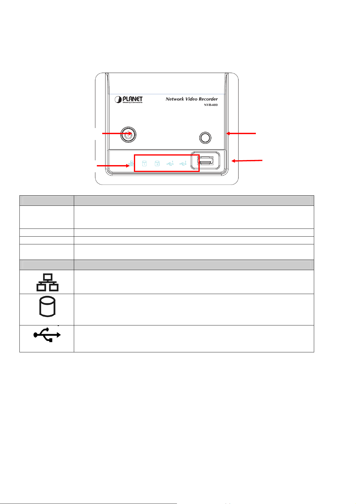
Front Panel
Power Button Unmount Button
LED Icons
USB Port 1
Item Description
Press to turn on the device. Press and hold for about five seconds to turn off.
Power Button
When you press the button to boot, the button start blinking Blue, and then
becomes a steady Blue when the device is ready.
Unmount Button Press to safely remove the connected USB device on the USB Port 1.
USB Port 1 Connect the external USB backup device.
LED Icons
The LED icons on the front panel let you know the related status of your device.
See the following table for more information of the LED icons.
Icon Description
A steady Green (1000 Mbps) or Amber (10/100 Mbps) light indicates the device
is connected to your LAN.
When it blinks, the device is receiving/ transmitting data from/to the network.
A steady Green light indicates the hard disk drive is installed in the device. A
blinking Green light indicates the installed hard disk drive is reading/writing data.
1 / 2
A steady Amber light indicates the hard disk drive is complete full (100%). A
blinking Amber light indicates the hard disk drive is getting full (95%).
The LED off indicates no USB devices is connected to the device. When you
connect the USB device to the device, the LED becomes a steady Green light.
1 / 2
When it blinks, the device is receiving/ transmitting data from/to the USB device.
- 5 -
NVR-400 User Guide
Page 7
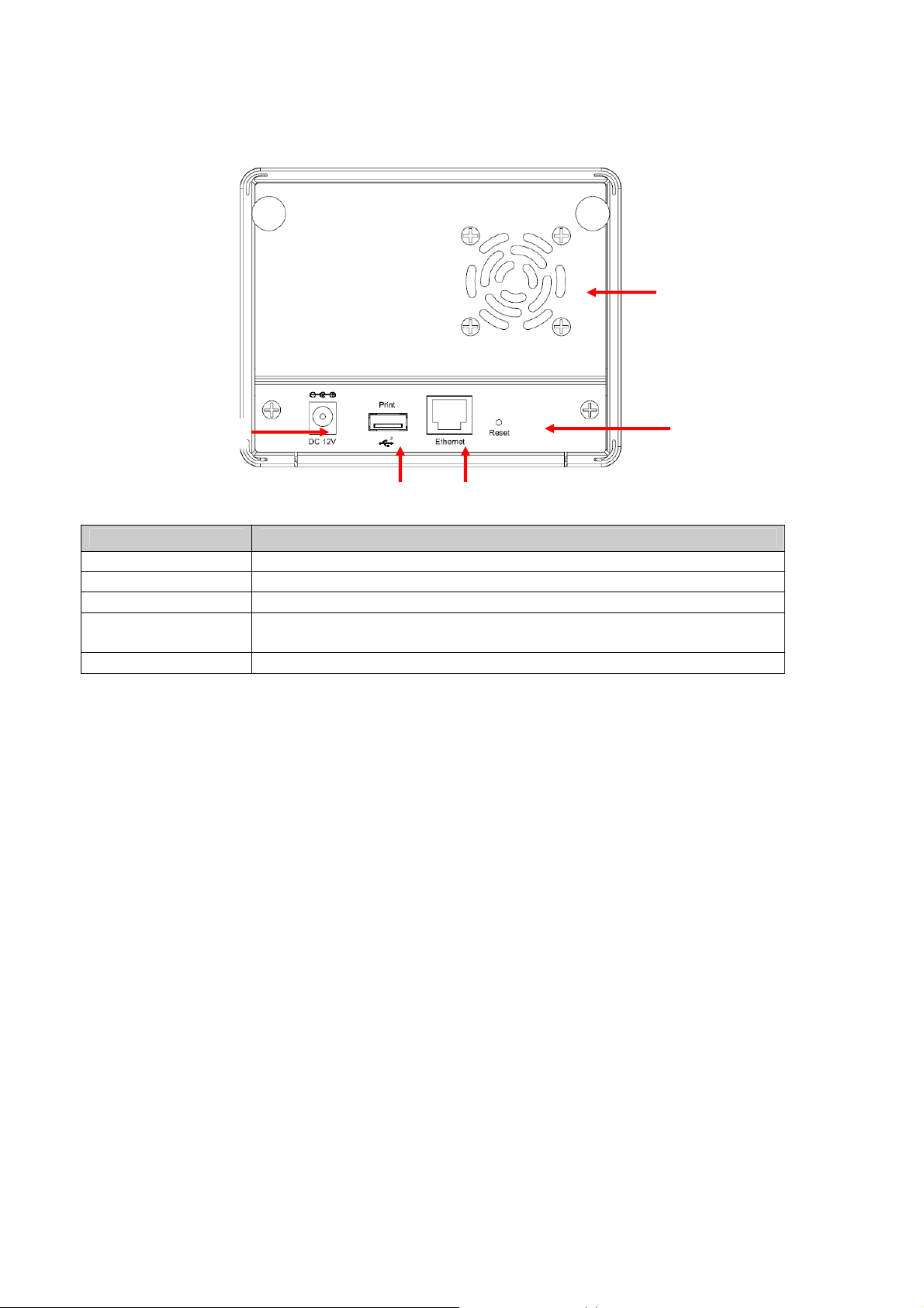
Rear Panel
Fan and Ventilator
DC 12V
Reset
USB Port 2
Ethernet
Item Description
DC 12V Plug the provided AC Power Adapter.
USB Port 2 Connect the USB printer (non-GDI interface).
Ethernet Plug the provided Ethernet Cable to connect to your LAN.
Reset
Press to reset the device. Press and hold for about five seconds to
resume the factory default configuration.
Fan and Ventilator Do not block or cover the ventilator for air circulation.
- 6 -
Page 8
C
HAPTER 2 HARDWARE INSTALLATION
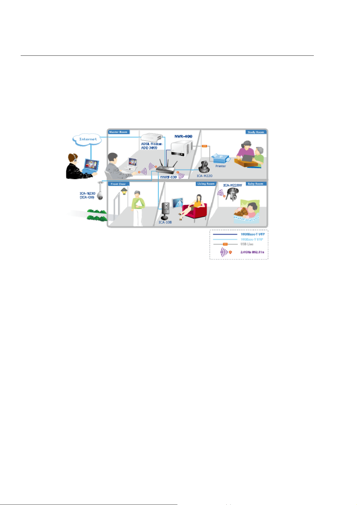
2.1 Networking Application
The following diagram explains the application of the Network Video Recorder within your
network. In the illustration below, the Network Video Recorder and four Internet cameras
are connected to a router/ switch, which minimize the impact of the network traffic for the
users within the network.
Network Video Recorder in your networking environment
- 7 -
NVR-400 User Guide
Page 9
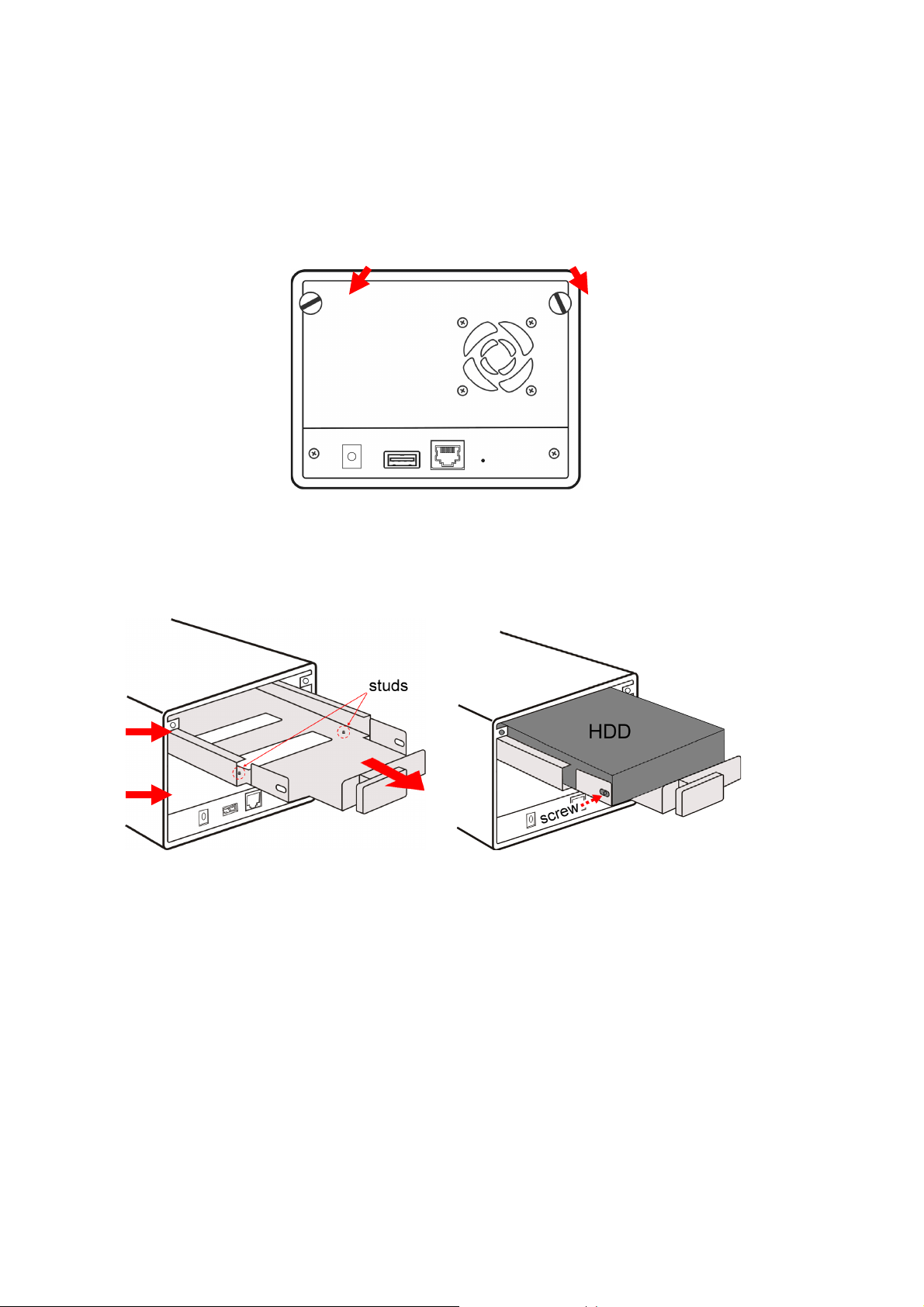
2.2 Installing the Hard Disk Drive
1. Disconnect the power cable of the device.
2. Remove two screws on the rear panel, and then remove the rear panel.
3. Pull the disk tray out until it jammed in the rack.
4. Place the hard disk drive on the tray, and then secured the screws on both side.
HDD 1
HDD 2
NOTE
While placing the hard disk drive onto the tray, align the screw holes on the bottom of hard disk
drive with the studs on the base of tray. The two studs are designed to ensure the hard disk drive
will be installed on the bracket securely.
5. Push the tray into the disk bay all the way until it connects the device.
6. Replace the rear panel and secure two screws.
- 8 -
Page 10
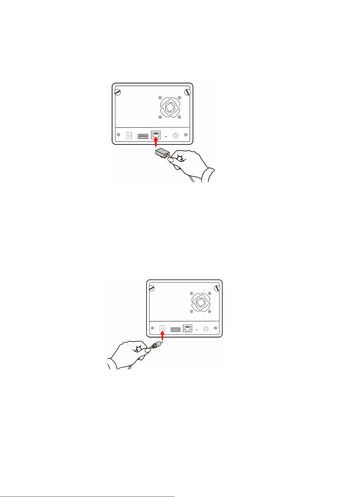
2.3 Connecting the Network
Plug an Ethernet cable to the LAN connector located on the device’s rear panel, and then
connect it to the network or directly to a computer for configuration.
Connecting the LAN cable
2.4 Connecting the Power Adapter
Plug the AC power adapter to the power connector located on the device’s rear panel, and
then connect it to your local power supply.
Connecting the power cable
- 9 -
NVR-400 User Guide
Page 11
C
HAPTER 3 ACCESSING THE DEVICE
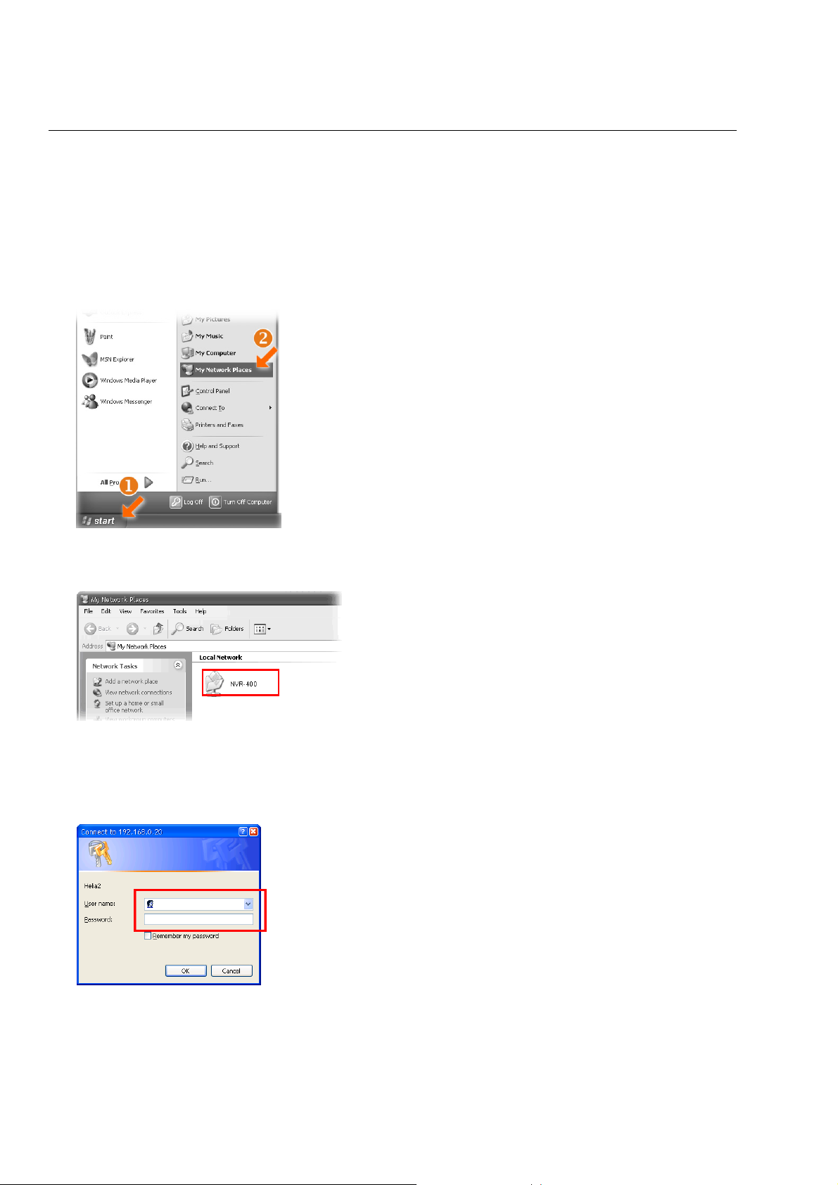
3.1 Accessing the device via My Network Places
Since you have built a connection between the Network Video Recorder and your PC, you
can easily access the device via My Network Places.
1. On your PC, click Start > My Network Places.
2. Find the device with its device named (such as NVR-400) in My Network Place.
3. Double-click the device icon. When the login window appears, enter the User name (the
default is admin) and password (the default is admin), and then click OK to access the
Network Video Recorder.
TIP
If you connect an USB device to the Network Video Recorder, it will be shown in the
window.
- 10 -
Page 12
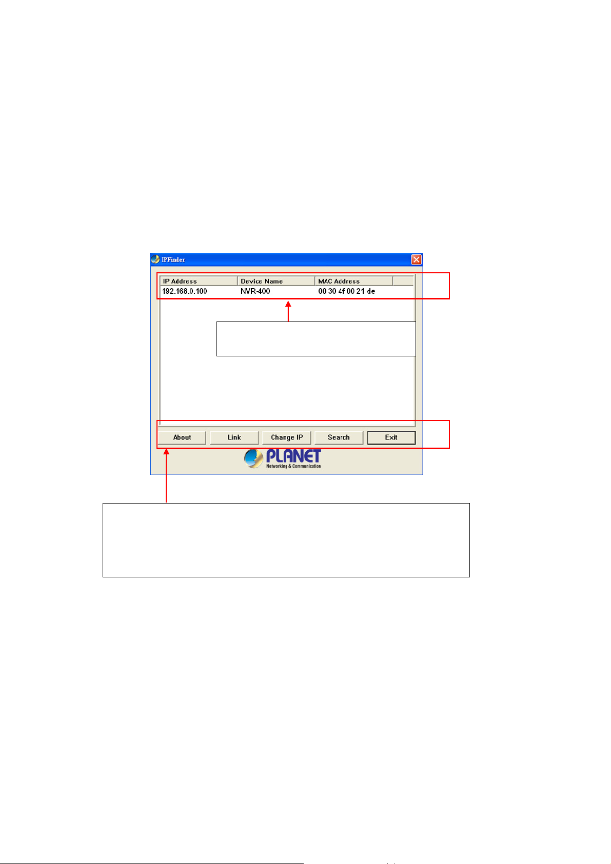
3.2 Using IPFinder
The device comes with a conveniently utility, IPFinder, which is included in the Installation
CD-ROM, allowing you to search the device on your network easily.
1. Insert the bundled CD-ROM into your computer’s CD-ROM Drive to initiate the AutoRun program.
2. Click the IPFinder item to launch the utility. The control panel will appear as below.
Display the connected device(s).
Double click to link the device.
Click About to get the Version information of IPFinder.
Click Link to connect the selected device.
Click Change IP to modify the IP address of the selected device.
Click Search to find the IP address of the connected device(s).
Click Exit to close the utility.
3. Once you get the IP address of the device, launch the Web browser to access your
device.
- 11 -
NVR-400 User Guide
Page 13
C
HAPTER 4 CONFIGURING THE DEVICE
You can easily access and manage the Network Video Recorder via the Web browser of
your PC. This chapter describes the Web Configuration Utility, and guides you through the
configuration of the device.
Since the default configuration of the device is DHCP mode enabled, you are
recommended to use IPFinder to search the IP address that is assigned to the device by
the DHCP server, and then click Link to access the camera via the Web browser.
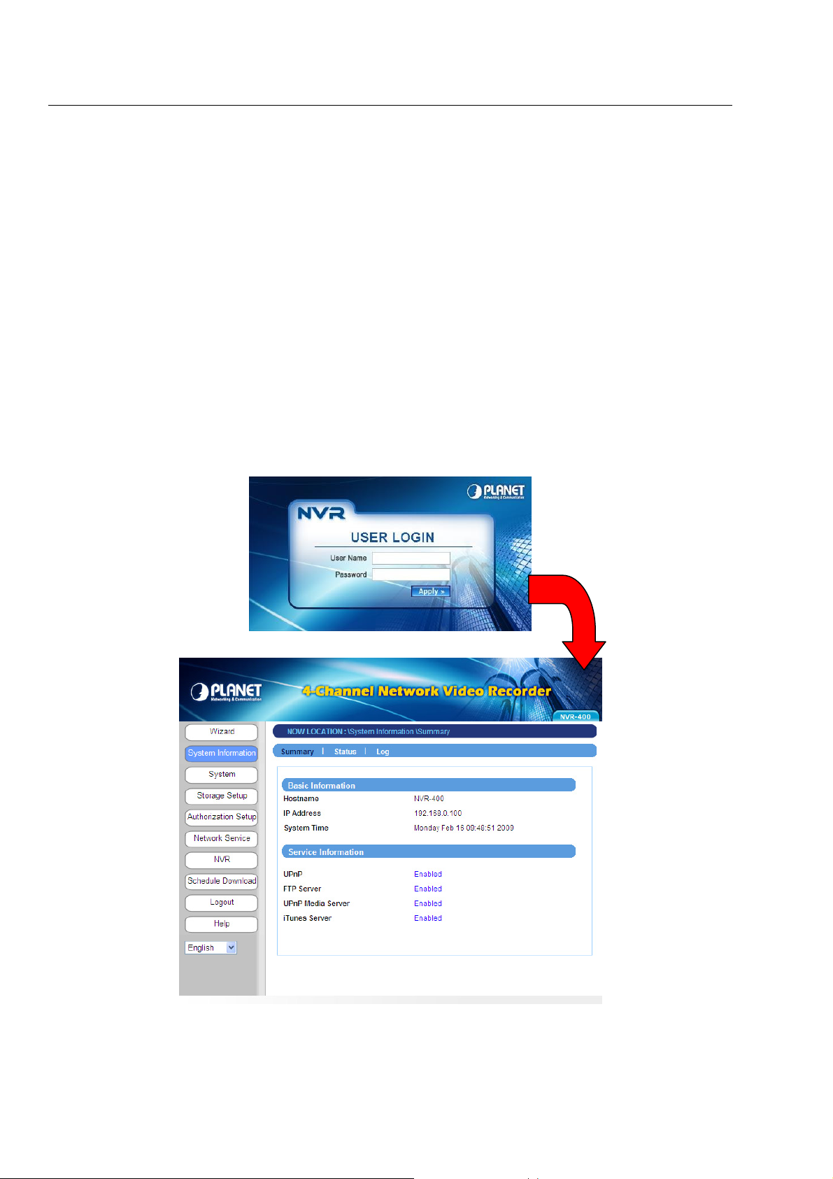
Login the Homepage
The Web management allows you to access and manage the Network Video Recorder
easily. Launch the Web browser and then enter the IP address. The default IP address is
192.168.0.100. And, fill the User Name and Password to login the Web management. The
default User Name / Password is admin / admin.
Web Configuration Utility of the device
- 12 -
Page 14

4.1 Using the Setup Wizard
The device’s Setup Wizard lets you configure your device easily and quickly. The wizard
will guide you through the necessary settings step-by-step.
To start the wizard, click Setup Wizard in the menu bar.
Step 1. LAN Setup
z Enter the Hostname for the device.
z Select Start UPnP to enable the device’s Universal Plug and Play function.
z If your network uses a proxy server, select Use proxy and enter the IP/Port values.
Step 2. TCP/IP Setup
z Select DHCP when your network uses the DHCP server; or select Static IP to
assign the IP address for the device directly.
For more information of TCP/IP settings, refer to the Lan section in Web
Configuration Utility.
- 13 -
NVR-400 User Guide
Page 15

Step 3. Set up Space Type
z Select Single Disk or RAID for storing the files.
For more information of space type, refer to the section 4.2.3 Storage Setup in Web
Configuration Utility.
Step 4. Setup Summary
z Display the configuration of the device.
When you complete the Setup Wizard, click Apply to reboot the device. Otherwise, click
Back to go back to the previous step(s) and change the settings.
- 14 -
Page 16

4.2 Using the Web Configuration Utility
After completing the Setup Wizard and rebooting the device, you can start to use the
Network Video Recorder within your network environment. However, you can configure the
advanced settings through the Web Configuration Utility.
The utility contains the following options in the menu bar: System Information, System,
Storage Setup, Authorization Setup, Network Service, NVR, Schedule Download,
Logout, and Help. Each option provides several related settings in the sub-menu area.
Click the desired option from the menu bar and then select the related setting to set up.
Sub-menu area
Menu bar
- 15 -
NVR-400 User Guide
Page 17

4.2.1 System Information
The System Information menu displays the current configuration and events log of the
device.
Summary
This sub-menu displays the hostname and IP address of the device, the date and time,
and the network service that you have set up.
Status
This sub-menu displays the firmware version of the device, the networking information,
the time zone, and the disk information.
Log
- 16 -
Page 18

This sub-menu displays the events log recorded by the system.
- 17 -
NVR-400 User Guide
Page 19

4.2.2 System
The System menu contains the basic system settings for the device, such as the
networking settings, time and date setup, etc.
Lan
- 18 -
Page 20

z LAN Setup
- Hostname: Enter a descriptive name for the device.
- Start UPnP: The device supports UPnP (Universal Plug and Play), which is a set
of computer network protocols that enable the device-to-device interoperability. In
addition, it supports port auto mapping function so that you can access the device
if it is behind an NAT router or firewall. Select the Enable option to enable this
feature.
- Use proxy: If your network uses a proxy server, select the Use proxy option and
then enter the IP/Port values.
z TCP/IP Setup
- DHCP: Select this option when your network uses the DHCP server. When the
device starts up, it will be assigned an IP address from the DHCP server
automatically.
- Static IP: Select this option to assign the IP address for the device manually. You
can use IPFinder to obtain the related setting values.
-
IP Address
Subnet Mask
Gateway
DNS 1/2
z Link Status
Display the connection status of the device.
Time
Enter the IP address of the device. The default setting is:
192.168.0.100.
Enter the Subnet Mask of the device. The default setting is:
255.255.255.0.
Enter the default Gateway of the device. The default setting
is: 192.168.0.254.
DNS (Domain Name System) translates domain names into
IP addresses. Enter the Primary DNS and Secondary DNS
that are provided by ISP.
- 19 -
NVR-400 User Guide
Page 21

z Time Zone
Select the proper time zone for the region from the pull-down menu.
z NTP Setup
Select this option and the time will be synchronized with the NTP Server. When you
select this option, you have to enter the IP address of the NTP server.
z Manual Setup
Select this option to set the date and time manually.
z Get time from my computer
Click the button and the date & time settings of the device will be synchronized with
the connected computer.
Once you complete the time and date setup, click Apply.
Notification
This sub-menu contains the required settings for e-mail notification feature. When you
complete the settings, click Send a test mail to test the related configuration is correct
or not. Once the device connects to the server successfully, click Apply.
z SMTP Server
Enter the mail server (e.g. mymail.com) in the box. Then, select the Authorization
check box and complete the following settings:
- User ID: Enter the user name to login the mail server.
- Password: Enter the password to login the mail server.
- Confirm Password: Enter the password again for confirmation.
z Sender E-mail
Enter the email address of the user (e.g. john@mymail.com) who will send the email.
z Primary/Secondary E-mail
Enter the first and second email address of the user who will receive the email.
- 20 -
Page 22

Configuration
z Delete all files
Select this option and click Apply to delete all files stored on the installed hard disk
drives.
z Format all disks and reset default
Select this option and click Apply to format the installed hard disk drives and reset
the device to the default configuration. Select the Keep log file check box to save
the log file when reset.
z Backup Config file
Select this option and click Apply to save the current customized configuration of
the device as a file on your PC.
z Restore Config file
Click Browse to find the configuration file, and then click Apply to restore the
customized configuration.
NOTE
Please remember to reboot your device when you clicked Apply button.
Firmware
This sub-menu displays the firmware version of the device. In addition, you can upgrade
the firmware once you have a latest version of firmware. When you are upgrading the
firmware, make sure that the device is connected to the power source during the
process. Otherwise, the device might be damaged because of failure of upgrading
firmware.
z Firmware file
Click Browse to find the firmware file and click Update.
- 21 -
NVR-400 User Guide
Page 23

4.2.3 Storage Setup
The Storage Setup menu provides the information and controls of the installed hard disk
drives, including the USB device.
NOTE
You are not recommended to use the USB device as your major storage device.
Space
Click Add to configure the storage space on the installed hard disk drives: selecting
Single Disk or RAID. Then, click Apply to start making file system.
- 22 -
Page 24

If you have two hard disks installed in the device, you can select a disk configuration for
RAID:
RAID 0
RAID 1
JBOD
(not recommended) Provide data striping.
(recommended) Provide mirroring over both disks.
(maximum data storage space) Combine both drives in a
linear fashion to create one volume.
When completed, the related information of the disks is displayed on the screen.
Click Add to add a storage space, or click Delete to remove the current storage space.
NOTE
Please remember to reboot your device when you clicked Apply button.
- 23 -
NVR-400 User Guide
Page 25

USB Disk
If you connect an external USB disk, this sub-menu displays the information of the USB
disk.
To safely remove the connected USB device, click unmount from this sub-menu. (The
other way is pressing the Unmount button on the front panel of the device for
disconnecting the USB Port 1.)
To reload the information of the connected USB devices, click refresh.
Click format to format the connected USB disk.
NOTE
Please remember to reboot your device when you clicked “apply” button.
Share Folder
This sub-menu allows you to specify the shared folder of the disks. Click Add and then
assign the destination folder from the Share Folder list and give a brief instruction in the
Comment box.
The Authority option allows the administrator to limit the usage of the shared folder.
Select the authority type (Read/Write or Read Only) from the list to meet your need.
Finally, assign the storage location from the Volume list.
- 24 -
Page 26

When completed, click Apply to add the folder that you assigned. You can then use the
File Explorer on your PC to check the folder that will be displayed as the directory under
the device name.
To change the setting, select the folder from the Share folder list and then click Edit.
To remove, select it and then click Delete.
NOTE
Please remember to reboot your device when you clicked Apply button.
File Management
This sub-menu displays the log of file system that you have made in the device.
- 25 -
NVR-400 User Guide
Page 27

4.2.4 Authorization Setup
The Authorization Setup menu allows you to manage the users and groups of the device.
User
Click Add and then assign the user name in the Select User box, and give a brief
instruction in the User Description box.
If you have set up groups for organization, you can assign the user to a group from the
Group list.
Enter the password twice for the new user in the Password and Confirm Password
boxes, and then select the Permission type (Admin or User).
Specify the storage quotas for the user from the Quota option of Space Status.
When completed, click Apply to add the user. You can change the user’s setting by
selecting the user and then clicking Edit, or remove the user by selecting the user and
then clicking Delete.
NOTE
Please remember to reboot your device when you clicked Apply button.
- 26 -
Page 28
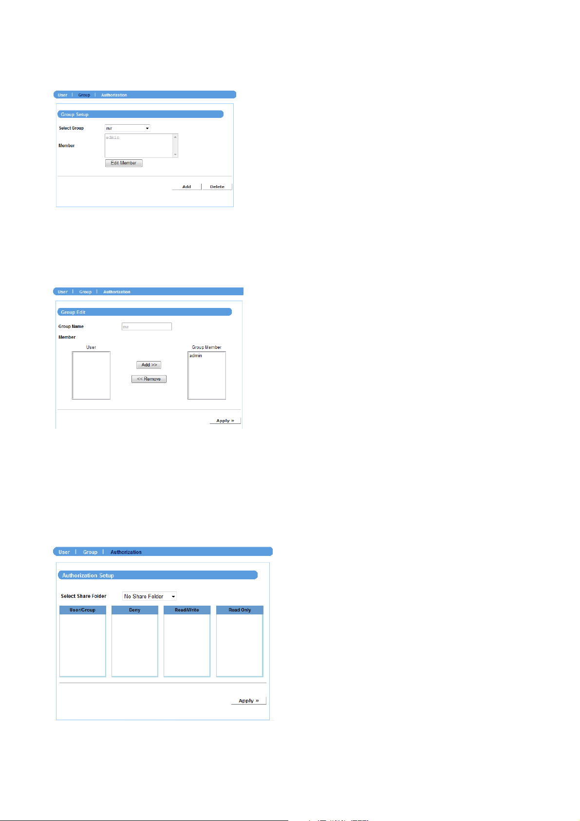
Group
Click Add and then assign the group name in the Group Name box, and then you can
add/remove users for the group from the Member option.
When completed, click Apply to add the group. To organize the users for the group,
click Edit Member. To remove the group, select it from the list and then click Delete.
Authorization
This sub-menu displays the assigned access rules and quotas of the users and groups.
- 27 -
NVR-400 User Guide
Page 29

4.2.5 Network Service
The Network Service menu allows you to set up the network services for the device, such
as FTP server, UPnP media server, etc.
Windows OS
z Windows Network Setup
- Workgroup: Enter the workgroup name where the device is installed within your
network.
- WINS Server: WINS (Windows Internet Name Service) server is used to support
NetBIOS over TCP/IP (NetBT). Enter the IP address of the WINS server in the box,
otherwise you cannot connect to a remote network resource by using its NetBIOS
name.
- 28 -
Page 30

FTP
This sub-menu contains the options that allow you to enable/disable the FTP service of
the device.
z Start FTP Service
Select this option to enable the FTP server of the device. Once you start the FTP
service, you should assign the FTP Port (the default is port 21) .
User transmission limitation
Specify the maximum upload and download speed (KB/s) by entering the proper
values in the related boxes.
UPnP Media Server
The device supports UPnP (Universal Plug and Play) and port auto mapping function so
that you can access the device if it is behind an NAT router or firewall. Select this option
to enable the UPnP media server and then assign the Path from the list.
- 29 -
NVR-400 User Guide
Page 31

iTunes Server
The device features an iTunes Server. It provides the ability to share files to the
computer on the local network running iTunes. If the function is enabled, the device will
be automatically detected in the iTunes program and the files contained in the specified
directory will be available to stream over the network.
Select this option to enable the iTune server and then assign the Path from the list. You
can also set up the Use Password to avoid unauthorized access.
USB Printer (only when an USB printer is connected)
When you connect an USB printer to the USB Port 2 of the device, this sub-menu
displays the information of the USB printer.
- 30 -
Page 32

4.2.6 NVR
The NVR menu allows you to add Internet cameras and view the live video.
IP Camera Backup
Click Auto Add to add the camera automatically, or click Add and to add the camera
manually through the following setup window:
- 31 -
NVR-400 User Guide
Page 33

z IP
Enter the IP address of the camera.
z HTTP Port
Assign the HTTP Port for the camera (the default is 80).
z RTSP Port
Configure the transmission of streaming data within the network. The default RTSP
(Real Time Streaming Protocol) port is 554.
z User ID/Password
Enter the user name and password for accessing the camera.
z Cam Vendor
Select the manufacturer of the camera from the list.
PLANET1: ICA-108 / 108W / 120 / 230 / 310 / 312 / 350 / 501 / 525 / 530 / 601 / 651
/ M230 / IVS-110
PLANET2: ICA-M220 / M220W
PLANET3: ICA-510 / 700
PLANET4: ICA151 / 750
z Split file
When the recorded file is too large, use this option to split it by selecting file size.
z Space
Specify the storage space for the camera.
z Motion Enable
Enable of disable the motion detection of the camera (if have).
z Recycle
Enable of disable the recycling function when the storage space on the device is full.
z Limit
Select Yes to limit the recording file by specifying the storage volume from the list.
Otherwise, select No to record without limitation.
When completed, click Next to set up the schedule for using the camera, and then click
Apply to add it to the list.
You can then change the configuration of the camera by selecting it from the list and then
clicking Edit. To remove a camera, select it and then click Delete.
- 32 -
Page 34

Quad View
In the Quad View screen, you can view the live video from the connected camera. You
can view up to four cameras simultaneously.
- 33 -
NVR-400 User Guide
Page 35

4.2.7 Schedule Download
The Schedule Download menu allows you to set up download schedule.
Click Add and the following setup window will appear:
Please input the file name.
z Login
Select Anonymous or Account from the list according to the settings of the target
server. If you have to select Account to login, you should enter the correct User
name and Password.
z URL
Enter the URL address of target server.
z Save To
Assign the destination folder from the list to save the downloaded files.
z When
From the Date and Time setting options, set up the start-up time to download files.
z Backup
Enable the backup function of your device by selecting None, Every Day, Every
Week, or Every Month, as well as the Time.
When completed, click Apply to save this download task to the Schedule List.
You can delete the download task by selecting it from the Schedule List and then clicking
Delete. When you change the settings of selected task, click Refresh to reload the status
of these tasks.
- 34 -
Page 36

4.2.8 Logout
The Logout menu allows you to exit or shutdown the system.
Logout
From this sub-menu, click Apply to exit the Web Configuration Utility and go back to the
Login window.
Shutdown
From this sub-menu, you can do one of the following:
z Select Shutdown Now and click Apply to turn off the device.
z Select Reboot and click Apply to reboot the device.
- 35 -
NVR-400 User Guide
Page 37

4.2.9 Help
The Help menu displays the information for each setting option of the device. Click the topic
(marked as blue color) to link to the corresponding page and view the related information in
detail.
- 36 -
Page 38

A
PPENDIX
Specifications
General
OS Embedded Linux
Ethernet 1 x RJ-45, 10/100/1000 Base-TX
USB Interface 2 x USB2.0 for backup device and printer
Storage Device 2 x 3.5” SATA hard disk
Button Shut down button, Unmount button, Reset button
LED Display 1 x LAN, 2 x HDD, 2 x USB
HDD Configuration Standard, RAID 0, 1 and JBOD
Video Input 4 channels IP camera
Recording Mode Manual, Schedule
Network Service TCP/IP, DHCP, DNS, HTTP, FTP, NTP, SMTP, UPnP
Network File Protocol Microsoft Networks (CIFS/SMB), Internet (HTTP), FTP
Web-based administration
Network Time Protocol
Management
Multiple users account
E-mail notification
System log
Firmware upgrade
File System Type
User Interface
Multiple Language Yes
Internal HDD support: XFS
External USB drive support: FAT32 / EXT3
IE browser
IPFinder utility
USB Compatible List
USB Flash Disk
Vendor Model
Apacer Technology Inc. Handy Steno 2.0/HT203
CompUSA 1GB Flash Drive
Kingston Technology Company Inc. DataTraveler 2.0 4GB Flash Drive
Microdia iFlash SM-Direct Card Reader
Phison Electronics Corp. AES1600
Alcor Micro Corp. Transcend JetFlash Flash Drive
Kingston Technology Company Inc. Patriot Xporter 4GB
Alcor Micro Corp. Transcend JetFlash Flash Drive
Ours Technology Inc. OTI-6803 Flash Disk
Realtek Semiconductor Corp. Mass Storage Device
Ours Technology Inc Transcend JetFlash 2.0 / Astone USB Drive
Imation Corp. 6155 Phone Parent
Silicon Integrated Systems Corp. Super Flash 1GB / GXT 64MB Flash Drive
USB Printer
Vendor Model
HP LJ-1020
Canon IP1880
Fuji Xerox Doc Print 203A.
- 37 -
NVR-400 User Guide
Page 39

Motion Detection Configuration
Example for ICA-530
1. At NVR page, please click “yes” in Motion Enable item.
2. At Network Service page, Please Enable the FTP Service.
- 38 -
Page 40

3. Login ICA-530 and set up an object detection area.
4. At Event Server page, please add NVR as the FTP Server.
Notice that the FTP Path must be the corresponding camera folder.
- 39 -
NVR-400 User Guide
Page 41

5. At Event Schedule page, first you have to enable the motion detection. Second, select the item of
Sending FTP.
6. Go back to NVR page and click start job.
Notice that if you want to stop motion detection, please stop it in ICA-530 first. Then click the
stop job button in NVR page.
- 40 -
Page 42
Example to ICA-M220
1. The same as ICA-530.
2. The same as ICA-530.
3. The same as ICA-530.
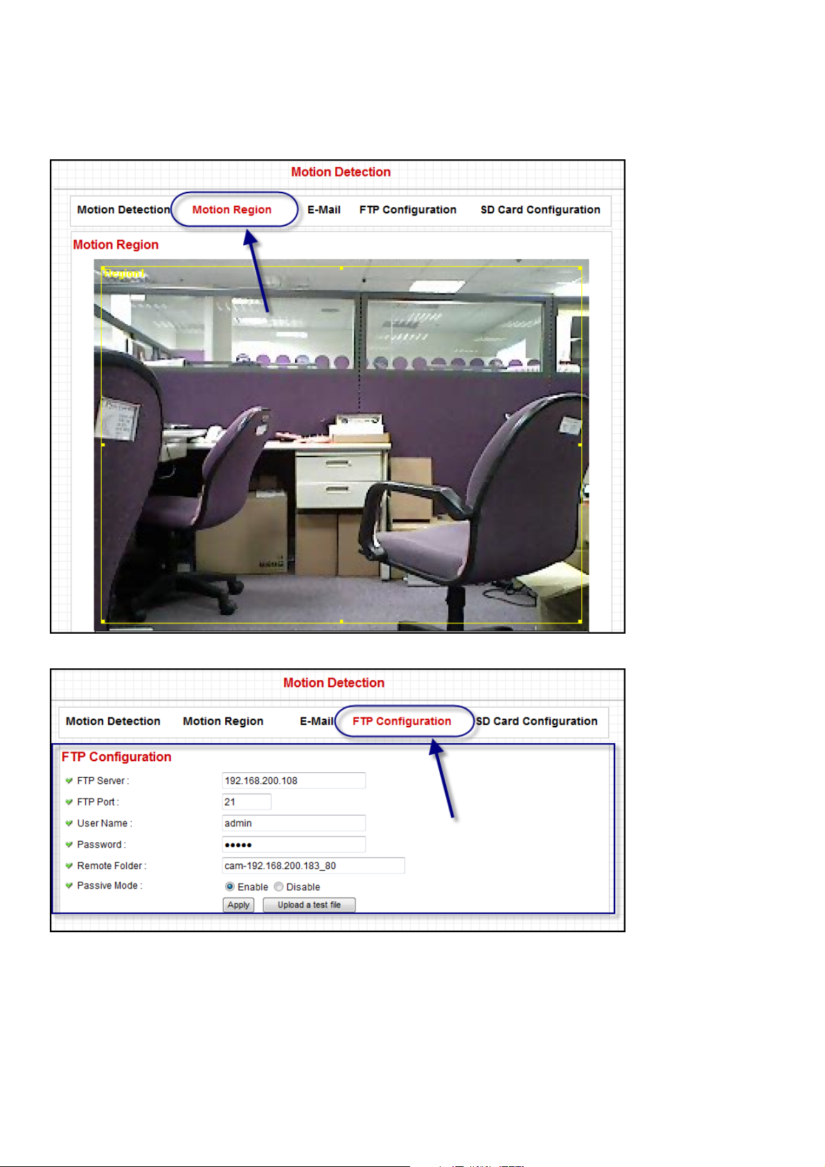
4. Login ICA-M220 and set up an object detection area.
5. Please add NVR as the FTP Server.
- 41 -
NVR-400 User Guide
Page 43

6. Enable motion detection and select the item of Send snapshot file to FTP.
7. Go back to NVR page and click start job.
- 42 -
 Loading...