

Page 1
NAS-7450 / NAS-7850
User’s manual
Version 1.0.0
Page 2

Copyright
Copyright © 2011 by PLANET Technology Corp. All rights reserved. No part of this
publication may be reproduced, transmitted, transcribed, stored in a retrieval system, or
translated into any language or computer language, in any form or by any means, electronic,
mechanical, magnetic, optical, chemical, manual or otherwise, without the prior written
permission of PLANET.
PLANET makes no representations or warranties, either expressed or implied, with respect
to the contents hereof and specifically disclaims any warranties, merchantability or fitness
for any particular purpose. Any software described in this manual is sold or licensed “as is”.
Should the programs prove defective following their purchase, the buyer (and not PLANET,
its distributor, or its dealer) assumes the entire cost of all necessary servicing, repair, and
any incidental or consequential damages resulting from any defect in the software. Further,
PLANET reserves the right to revise this publication and to make changes from time to time
in the contents hereof without obligation to notify any person of such revision or changes.
All brand and product names mentioned in this manual are trademarks and/or registered
trademarks of their respective holders.
Federal Communication Commission Interference Statement
This equipment has been tested and found to comply with the limits for a Class B digital
device, pursuant to Part 15 of FCC Rules. These limits are designed to provide reasonable
protection against harmful interference in a residential installation. This equipment
generates, uses, and can radiate radio frequency energy and, if not installed and used in
accordance with the instructions, may cause harmful interference to radio communications.
However, there is no guarantee that interference will not occur in a particular installation. If
this equipment does cause harmful interference to radio or television reception, which can
be determined by turning the equipment off and on, the user is encouraged to try to correct
the interference by one or more of the following measures:
1. Reorient or relocate the receiving antenna.
2. Increase the separation between the equipment and receiver.
3. Connect the equipment into an outlet on a circuit different from that to which the
receiver is connected.
4. Consult the dealer or an experienced radio technician for help.
FCC Caution
To assure continued compliance. (example-use only shielded
interface cables when connecting to computer or peripheral devices). Any changes or
modifications not expressly approved by the party responsible for compliance could void the
user’s authority to operate the equipment.
This device complies with Part 15 of the FCC Rules. Operation is subject to the Following
two conditions: ( 1 ) This device may not cause harmful interference, and ( 2 ) this Device
must accept any interference received, including interference that may cause undesired
operation.
Federal Communication Commission (FCC) Radiation Exposure Statement
This equipment complies with FCC radiation exposure set forth for an uncontrolled
environment. In order to avoid the possibility of exceeding the FCC radio frequency
exposure limits, human proximity to the antenna shall not be less than 20 cm (8 inches)
during normal operation.
i
Page 3

R&TTE Compliance Statement
This equipment complies with all the requirements of DIRECTIVE 1999/5/CE OF THE
EUROPEAN PARLIAMENT AND THE COUNCIL OF 9 March 1999 on radio equipment and
telecommunication terminal Equipment and the mutual recognition of their conformity
(R&TTE)
The R&TTE Directive repeals and replaces in the directive 98/13/EEC (Telecommunications
Terminal Equipment and Satellite Earth Station Equipment) As of April 8, 2000.
Safety
This equipment is designed with the utmost care for the safety of those who install and use it.
However, special attention must be paid to the dangers of electric shock and static
electricity when working with electrical equipment. All guidelines of this and of the computer
manufacture must therefore be allowed at all times to ensure the safe use of the equipment.
WEEE regulation
To avoid the potential effects on the environment and human health as a result of the
presence of hazardous substances in electrical and electronic equipment, end users
of electrical and electronic equipment should understand the meaning of the
crossed-out
wheeled bin symbol. Do not dispose of WEEE as unsorted municipal waste and
have to collect such WEEE separately.
Revision
User’s Manual for PLANET 4-Bay/8-Bay SATA NAS RAID Server
Model: NAS-7450/7850
Rev: 1.0 (Dec. 2010)
Part No. EM-NAS-7450/7850
ii
Page 4

Chapter 1 Introduction...........................................................................................................5
1.1 NAS-7450 overview............................................................................................................... 5
1.2 NAS-7850 overview............................................................................................................... 8
Chapter 2 Installing and Starting NAS system..................................................................11
2.1 Installing the NAS-7450/NAS-7850 rack-mount Model .................................................11
2.2 Sliding Rails Installation...................................................................................................... 13
2.3 Accessing the Administration Home Page ......................................................................18
2.4 Detection of Chassis Intrusion ..........................................................................................18
Chapter 3 Server Configuration..........................................................................................19
3.1 Server Information and Settings........................................................................................ 19
3.2 Upgrading the Firmware ..................................................................................................... 20
3.3 Shutting Down the Server .................................................................................................. 20
3.4 Enabling UPS Support........................................................................................................ 21
3.5 Modifying the Administrator’s Password.......................................................................... 24
Chapter 4 Network Configuration.......................................................................................25
4.1 Network Information ............................................................................................................25
4.2 TCP/IP Settings ................................................................................................................... 27
4.3 Windows Settings ................................................................................................................28
4.4 UNIX/Linux Settings ............................................................................................................29
4.5 Macintosh Settings ..............................................................................................................31
4.6 Web Data Access Settings................................................................................................. 33
4.7 FTP Data Access Settings ................................................................................................. 34
4.8 SNMP Settings..................................................................................................................... 35
4.9 Email Settings ...................................................................................................................... 36
4.10 SSL Settings ......................................................................................................................38
Chapter 5 Storage Management .........................................................................................39
5.1 Volume Usage and Status .................................................................................................39
5.2 Creating a Volume............................................................................................................... 41
5.3 Deleting a Volume ............................................................................................................... 43
5.4 Expanding a RAID-5 Volume............................................................................................. 43
5.5 Volume/Disk Scan ............................................................................................................... 43
5.6 Assigning Hot-spare Disks................................................................................................. 44
5.7 Migrating Data Volumes ..................................................................................................... 45
5.8 Hot-swapping ....................................................................................................................... 45
5.9 iSCSI...................................................................................................................................... 46
Chapter 6 Security Control..................................................................................................48
6.1 Security Information ............................................................................................................ 48
6.2 Creating the Local User and Local Group Accounts...................................................... 49
6.3 Caching Windows Domain User Accounts...................................................................... 51
6.4 Creating UNIX/Linux Host ..................................................................................................52
6.5 Creating Share and Assigning Share Permissions ........................................................ 54
3
Page 5

6.6 Configuring File and Folder Security and ACL................................................................ 56
6.7 Managing Quotas ................................................................................................................ 59
Chapter 7 User Access ........................................................................................................62
7.1 Workgroup or Domain Mode.............................................................................................. 62
7.2 Accessing from Windows ................................................................................................... 62
7.3 Accessing from Web Browsers .........................................................................................64
7.4 Accessing from MacOS ...................................................................................................... 66
7.5 Accessing from FTP Clients............................................................................................... 67
7.6 Accessing from NFS Clients .............................................................................................. 68
Chapter 8 Backup and Recovery ........................................................................................70
8.1 Snapshot – Fast Point-In-Time Copies ............................................................................ 70
8.2 SmartSync – NAS-to-NAS Data Replication ...................................................................73
8.3 Backup and Restore System Profiles............................................................................... 78
8.4 Backup USB Device............................................................................................................ 79
Chapter 9 Event Logs and System Status .........................................................................81
9.1 Thermal Settings.................................................................................................................. 82
9.2 Checking the Event Logs.............................................................................................. 82
9.3 Viewing System Status....................................................................................................... 83
9.4 Saving System Settings and Status as HTML Files....................................................... 84
9.5 Share Access Counts .........................................................................................................85
Chapter 10 Virus Protection................................................................................................86
10.1 Information.......................................................................................................................... 86
10.2 Real-time, Manual and Schedule Scanning .................................................................. 87
10.3 Configuring Scan Settings ...............................................................................................88
10.4 Updating Virus Pattern File.............................................................................................. 89
Appendix A Troubleshooting & Frequently Asked Questions.........................................90
Appendix B Utility for NAS system.....................................................................................92
Appendix C LED Indicators...............................................................................................105
Appendix D Product Specification ...................................................................................106
4
Page 6

Chapter 1 Introduction
1.1 NAS-7450 overview
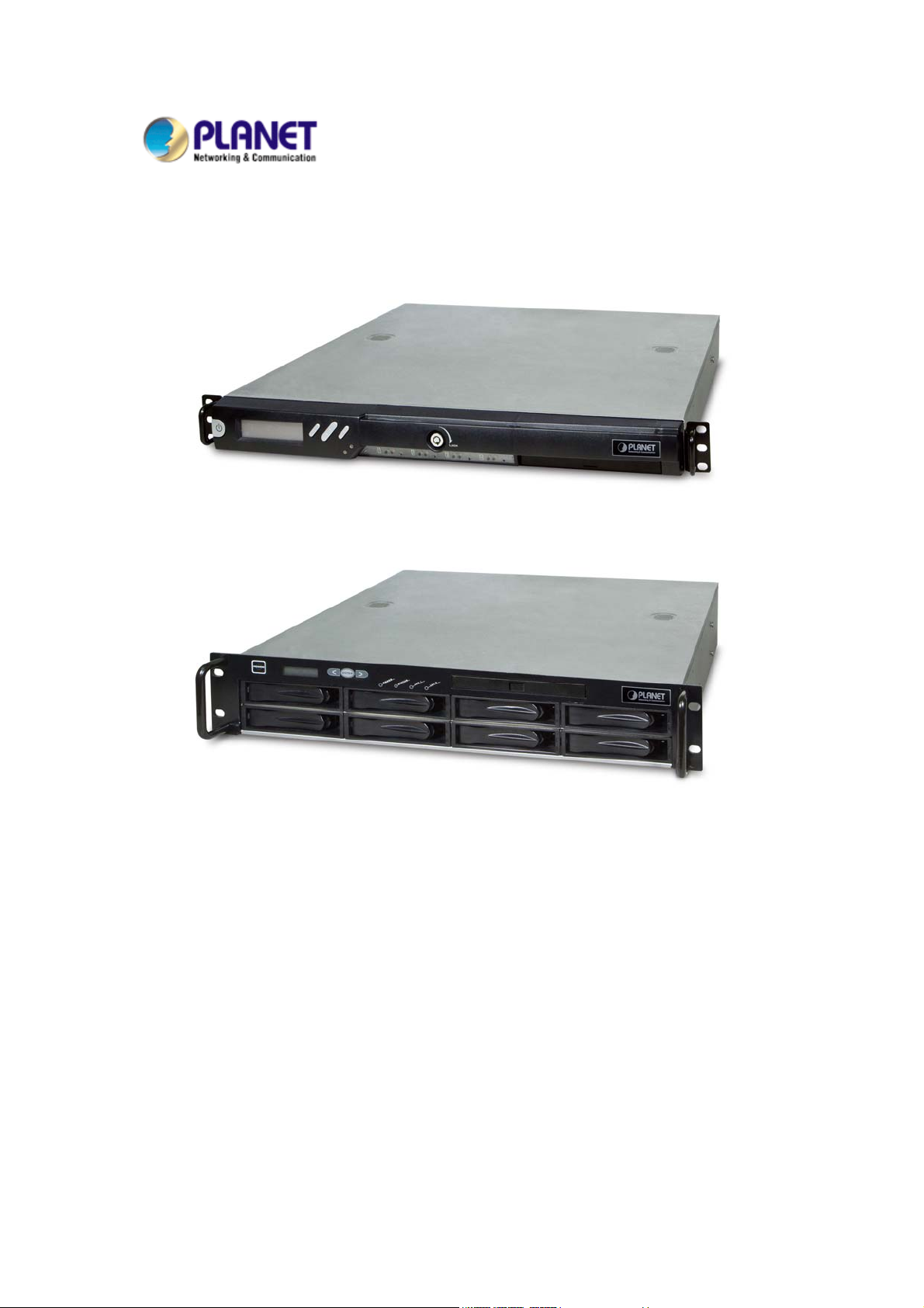
The reliable and high-performance business-class network storage, PLANET NAS-7450 is a 1U
4-Bay rack-mountable unified network storage system designed for those seeking reliable and
affordable server virtualization and file storage. The network storage unified architecture supports
both NAS and IP-SAN applications and solves numerous data management problems with a single
system. Integrated data protection and offsite replication features make managing complex business
storage environments affordable.
The NAS-7450 provides advanced RAID configurations including RAID 0, 1, 5, 6 and 10 functions.
The HDD space in use can easily increases up to double with RAID-0 or real-time data backup to
prevent data lost with RAID-1. The basic RAID function will ask user to install two hard drives in the
same model when storing data, however, it also supports hot-swap design so that a failed drive can
be replaced by hot swapping without turning off the server. Besides, the best-in-class RAID on the
NAS brings users a higher level of data security by allowing one more hard drive failure than other
NAS with similar functions.
The NAS-7450 is equipped with the Intel Celeron processor, and it is a powerful 4-Bay network
attached storage (NAS) server, which is designed to provide a cost-efficient and easy-to-use solution.
It supports advanced user management functions such as private HDD space and login account. It
not only shares HDD space, but also positions as the central management device managing each
user of the device. With the NAS-7450, business-class office or home users will get a simple yet
effective way to expand the client side or the network data storage.
1.1.1 Features
High-density 1U rack-mount, extreme energy efficiency and simple serviceability
Multiple volume support for RAID 0, 1, 5, 6, 10 background sync and Smart Sync resume
Simultaneously supports NAS and iSCSI SAN for database and server virtualization
applications
Two 10/100/1000 Ethernet ports with load balancing and failover
High-end Data Protection adopts the most advanced SATA RAID technology and fully
integrates Anti-virus engine to protect valuable data on the fly
Multi-Protocol system support for Windows, MAC, Solaric, FreeBSD, Linux and other UNIX
derivatives
Revolutionary dual-function NAS server integrates both On-line file service into one
centralized storage server
High Performance: Using single device connection which eliminates the master/ slave issues
and allows faster transfer rate without latency and delay
High Data Integrity: Offers error checking and error correcting capabilities
5
Page 7
The end-to-end integrity of transferred commands and data can be guaranteed across the
serial bus
High System Reliability: A dedicated port for each disk drive, providing greater system
reliability through individual drive and cable fault isolation
High Usability: Easier configuration and design with cables that are thinner, have smaller
connectors, and are simpler to route and install
1.1.2 Package Content
z
NAS-7450 x 1
z
Key x 2
z
Power Cord x 1
z
Screw Package x 1
z
User’s Manual CD x 1
z
Sliding Rail x 1 set
z
Quick Installation Guide x 1
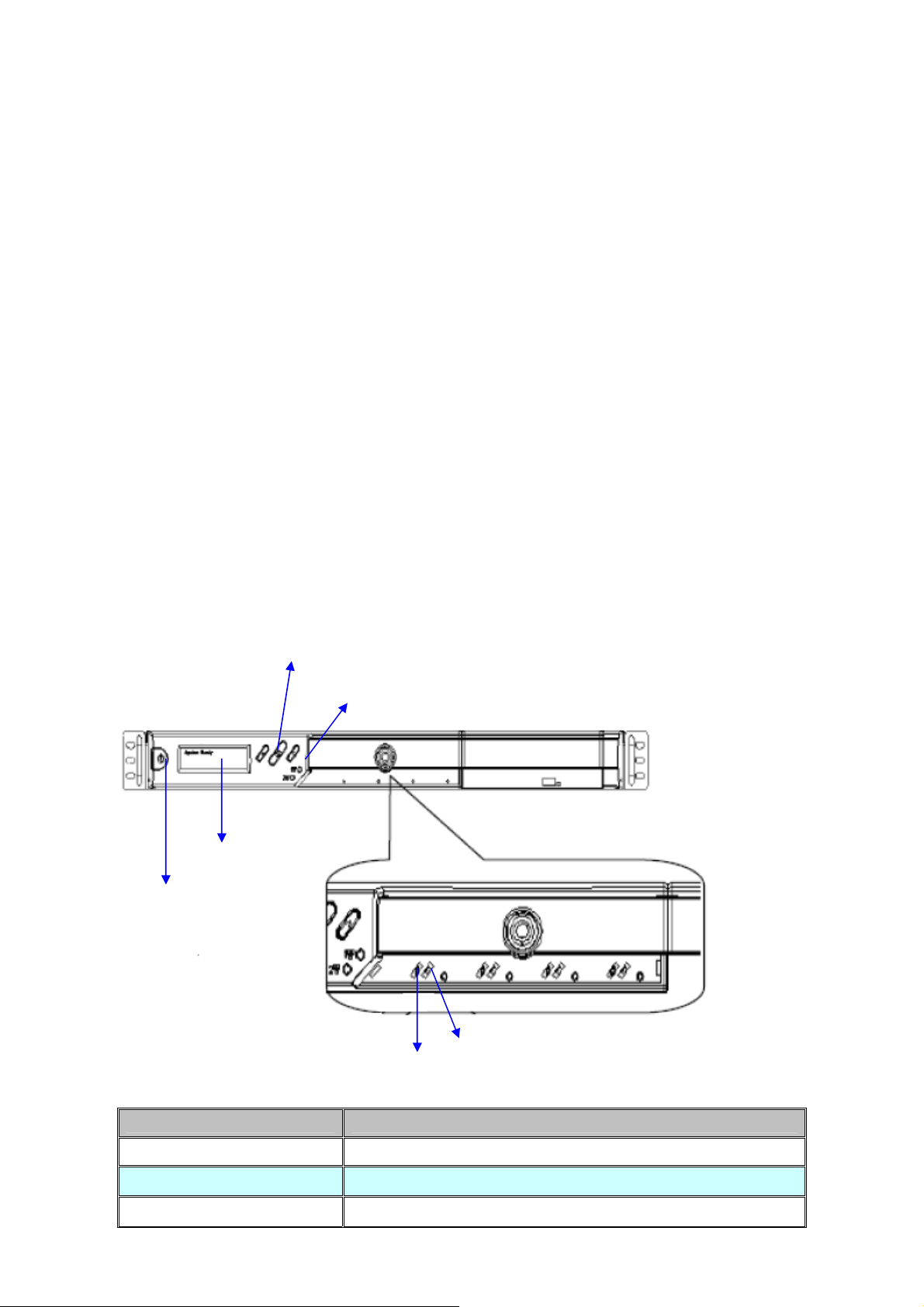
1.1.3 Physical Detail
LCD Panel
Power Button
NAS-7450 Front View
Control Button
LAN1 / LAN2 LED
HD Access LED
HD LED (Power/Fault)
Interface Description
Power Button Green(power on)、Yellow(default)
LCD Panel
Control Button
Display LAN1/LAN2 IP Information
Press the Control button to configure LAN1/LAN2 IP address.
6
Page 8
LAN1
LAN2
Yellow(10M link)、Green(100M link)、Amber(1000M link)
HD Access LED HD LED(Power/Fault)
Red on Green Blinks Powering up
Red On
Green On HDD is being accessed
during access
Red Blinks (Fast) Green Blinks (Fast) RAID building, rebuilding, expanding
Volume un-mounted and HDD is ready for being
Red off Amber on
hot-up plugged
Disk faulty.
Off Amber Blinks (Slowly)
Blinking interval is about 2 seconds
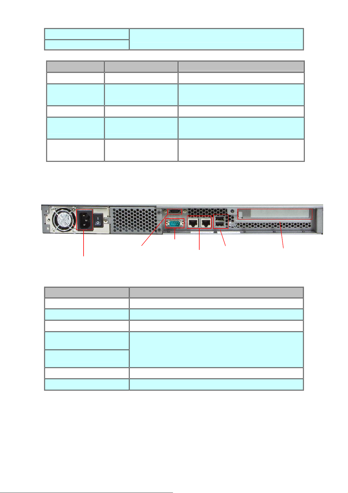
Description
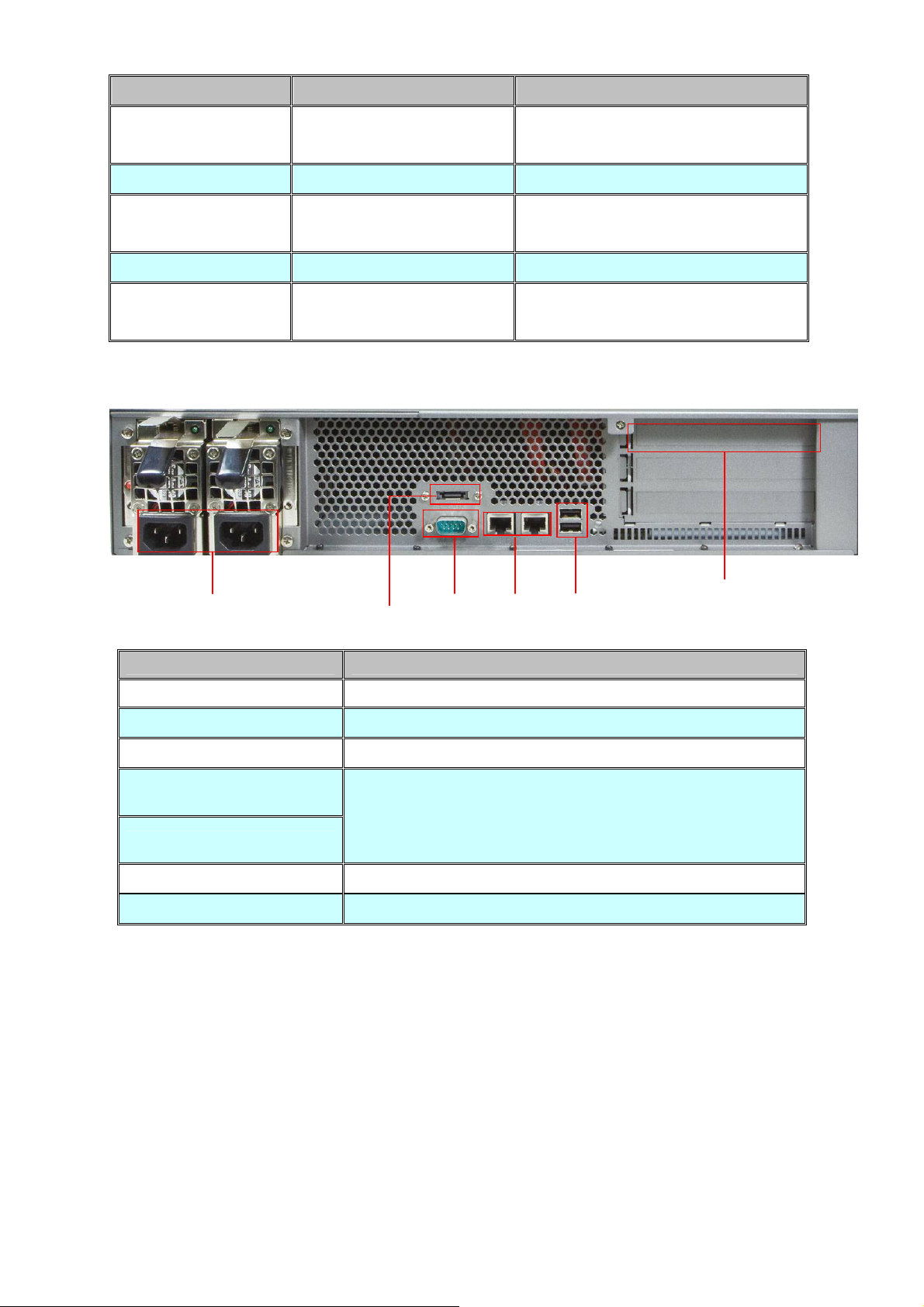
NAS-7450 Rear View
Power Jack
Interface Description
Power Jack Connect the two power supply cord shipped with the system
e-SATA
RS-232
LAN Jack (LAN1)
LAN Jack (LAN2)
USB Socket Connect to UPS and external HDD(FAT/FAT32)
PCI-E Port (optional)
RS-232
e-SATA
Connect to External hard drive case
Connect to UPS
These RJ-45 ports support auto negotiating Fast Ethernet
10/100/1000 Base-TX networks. That allows your system to be
connected to an Internet Access device, e.g. router, cable
modem, ADSL modem, through a CAT.5 twisted pair Ethernet
cable.
Connect to Tape Backup or Tape Library or Network card
LAN Jack
USB
PCI-E
7
Page 9

1.2 NAS-7850 overview
The reliable and high-performance business-class network storage, PLANET NAS-7850 is a 2U
8-Bay rack-mountable with redundant power supplies network storage system designed for those
seeking reliable and affordable server virtualization and file storage. The network storage unified
architecture supports both NAS and IP-SAN applications and solves numerous data management
problems with a single system. Integrated data protection and offsite replication features make
managing complex business storage environments affordable.
The NAS-7850 provides advanced RAID configurations including RAID 0, 1, 5, 6 and 10 functions.
The HDD space in use can easily increase up to double with RAID-0 or real-time data backup to
prevent data lost with RAID-1. The basic RAID function will ask user to install two hard drives in the
same model when storing data, however, it also supports hot-swap design so that a failed drive can
be replaced by hot swapping without turning off the server. Besides, the best-in-class RAID on the
NAS brings users a higher level of data security by allowing one more hard drive failure than other
NAS with similar functions.
The NAS-7850 is equipped with the Intel Core 2 Duo processor, and it is a powerful 8-Bay network
attached storage (NAS) server, which is designed to provide a cost-efficient and easy-to-use solution.
It supports advanced user management functions such as private HDD space and login account. It
not only shares HDD space, but also positions as the central management device managing each
user of the device. With the NAS-7850, business-class office or home users will get a simple yet
effective way to expand the client side or the network data storage.
1.2.1 Features
High-density 2U 8-bay rack-mount with redundant power supplies for reliability and
business continuity
Multiple volume support for RAID 0, 1, 5, 6, 10 background sync and Smart Sync resume
Simultaneously supports NAS and iSCSI SAN for database and server virtualization
applications
Two 10/100/1000 Ethernet ports with load balancing and failover
High-end Data Protection adopts the most advanced SATA RAID technology and fully
integrates Anti-virus engine to protect valuable data on the fly
Multi-Protocol system support for Windows, MAC, Solaric, FreeBSD, Linux and other UNIX
derivatives
Revolutionary dual-function NAS server integrates both On-line file service into one centralized
storage server
High Performance: Using single device connection which eliminates the master/ slave issues
and allows faster transfer rate without latency and delay
High Data Integrity: Offers error checking and error correcting capabilities
The end-to-end integrity of transferred commands and data can be guaranteed across the
8
Page 10
serial bus
High System Reliability: A dedicated port for each disk drive, providing greater system
reliability through individual drive and cable fault isolation
High Usability: Easier configuration and design with cables that are thinner, have smaller
connectors, and are simpler to route and install
1.2.2 Package Content
‧ NAS-7850 x 1
‧ User’s Manual CD x 1
‧ Power Cord x 2
‧ Screw Package x 1
‧ Sliding Rail x 1 set
‧ Quick Installation Guide x 1
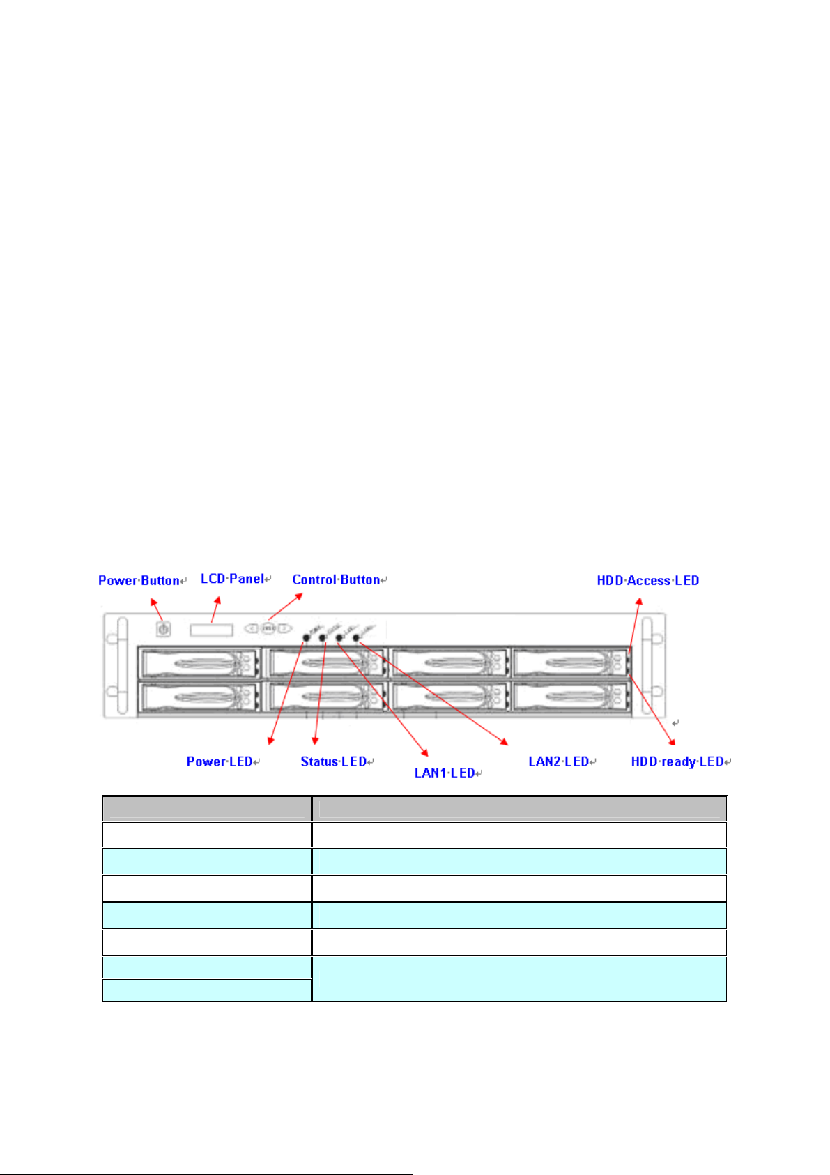
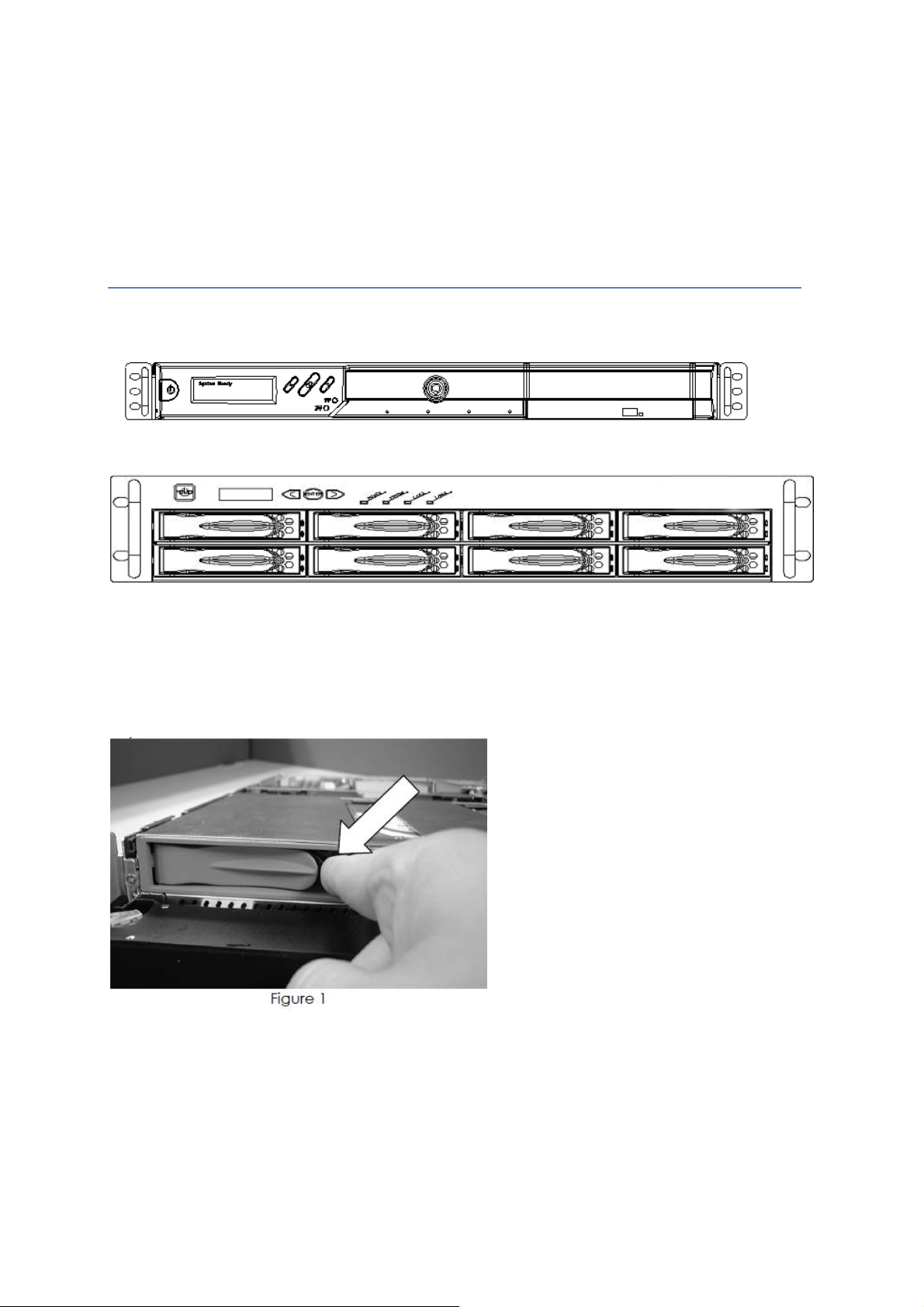
1.2.3 Physical Detail
Interface Description
Power Button Power on/off
LCD Panel
NAS-7850 Front View
Display LAN1/LAN2 IP Information
Control Button
Power LED
Status LED
LAN1 LED
LAN2 LED
Press the Control button to configure LAN1/LAN2 IP address.
Green(power on)、Yellow(default)
Yellow(default)
Yellow(10M link)、Green(100M link)、Amber(1000M link)
9
Page 11
HDD Access LED HDD ready LED Description
Red on
during access
Red on Green Blinks (FAST) RAID building, rebuilding, expending
Off
Off Amber Blink (Slowly) Disk fault Blinking interval is 2 second
Off Off Hard disk is absent or SATA
Green Blinks
Amber on Volume un-mounted and HDD is ready for
Power is being accessed
being hot-unplugged
cable is not connected
NAS-7850 Rear View
Power Jack
Interface Description
Power Jack Connect the two power supply cord shipped with the system
e-SATA
RS-232
LAN Jack (LAN1)
LAN Jack (LAN2)
USB Socket Connect to UPS and external HDD(FAT/FAT32)
PCI-E Port (optional)
e-SATA
RS-232
Connect to External hard drive case
Connect to UPS
These RJ-45 ports support auto negotiating Fast Ethernet
10/100/1000 Base-TX networks. That allows your system to be
connected to an Internet Access device, e.g. router, cable
modem, ADSL modem, through a CAT.5 twisted pair Ethernet
cable.
Connect to Tape Backup or Tape Library or Network card
LAN Jack
USB
PCI-E
10
Page 12
Chapter 2 Installing and Starting NAS system
This chapter covers the installation procedure of different form factors of NAS server as well as the
NAS-7450/NAS-7850 Mobile Rack. Instruction on how to startup the NAS server by setting up the basic
configuration through the Admin Home page or provided software tool – NAS Finder is also outlined in
this chapter.
2.1 Installing the NAS-7450/NAS-7850 rack-mount Model
NAS-7450
NAS-7850
Hot swap hard disk tray installation
1. To unlock the hot swap hard disk tray, pull the tab behind the end of the lever to release the latch and
then lift the lever up as far as it can go to disengage the hard disk tray from the chassis.
2. Pull the hard disk drive tray out.
3. Attached the HDD to the hot swap hard disk tray with the screws provided shown in Figure 2.
11
Page 13

Figure 2
4. Slide the hot swap hard disk tray slowly into the chassis, push the outer rim of the tray as shown in
Figure 3 until the lever retract slowly toward the tray. Then, push the level down as far as it can go to
connect the hot swap hard disk tray to the chassis.
NAS-7450/NAS-7850 rack-mount server installation
1. Pull out a HDD tray from the server.
2. Secure and mount a hard disk onto the HDD tray using four screws under the tray.
3. Insert the HDD tray back in the server. Make sure the lever of the HDD tray is properly in place.
4. Repeat Step 1 to Step 3 if necessary for the other HDD tray.
5. Install the provide rack mounting handles at both side of the NAS server.
6. Install the NAS server in the rack. (Refer to the paragraph “Sliding Rails Installation” in Chapter 2
section 5)
7. Connect your NAS server to the network by attach a LAN cable from the LAN port located at the back
of your NAS server.(At least one network connection is required)
8. Plug the power cord into the power connector on you NAS server.
9. Make sure the power switch on the power supply is in on position.
12
Page 14

10. Press the power button on the left hand corner of your NAS server.
11. Wait for the server to boot up. The boot up process takes approximately 2 minutes.
2.2 Sliding Rails Installation
1. Make sure that you have the following the mounting parts for the sliding rails.
• 4 L-shaped brackets (see the left side of the photo)
•
8 x “M4” size screws, 8 x “M5” size screws and 6 x “#6-32” size screws.
#6-32
2. Take the sliding rail apart by sliding out the center slide. Push down the hook to separate them. Pull
the center slide all the way until it reaches the end.
3. Now install the center slide to the rack-mount chassis. Find the screw holes on both sides of the
rack-mount chassis, which are used for mounting the center slide. Fasten the “#6-32” screws to fix
the center slides onto chassis. Later, the center slides will be used for attaching to the sliding rail.
13
Page 15

4. Next, attach the two L-shaped mounting brackets on to a sliding rail. Use the “M4” screws to
secure the L-shaped bracket on to the sliding rail.
5. Attach the sliding rail onto a rack-mount cabinet. Secure the sliding rail onto the rack-mount
cabinet via the screw holes on the L-shaped brackets
14
Page 16

After properly attaching both sliding rails to the rack-mount cabinet, you may slide the
rack-mount chassis (mounting) in to the cabinet.
Configuring the NAS using the LCD console
15
Page 17

Configuring the IP addresses using the LCD console
1. After NAS server is boot up, the LCD console shows System Ready. Press the right button.
2.
The IP address of LAN1 is shown. Press the middle button to configure LAN1 IP address.
Note that the
be configured using the LCD console.
symbol at the right hand upper corner indicates that the IP address can
3. Move the cursor to “Yes” by pressing the left button and then press the middle button to
confirm.
4. Move the cursor to the correct position using the left or right button. Then press the middle
button to change that number.
16
Page 18

5. After you edit the last digit of the IP address, press the right button and configure the Subnet
Mask address.
6. Repeat Steps 4 to Steps 5 to configure the Subnet Mask and Gateway address.
7. After you edit the last digit of the Gateway address, press the right button. Move the cursor
to Save and save the setting or Edit to repeat the above process or Abort to quit the
configuration process without saving.
8. Repeat the above process to configure the other LAN port.
Configuring the IP addresses using NAS Finder
You can use the provided utility NAS Finder to perform the initial setup of your newly arrived
NAS server. The utility designed to perform a quick set up and put your NAS server online in
just a few minutes. During startup, NAS Finder begins to discover the entire NAS server on the
network. The default server name would be “NASxxxxxxxx”, where “xxxxxxxx” is the last eight
digits of the Ethernet address of LAN1.
1. Highlight the server you want to configure from the left hand pane.
2. Click the
3. Or, right click the server and select “Configure”
4. Enter the “Server Name”, “Server Comment”, and “Workgroup/Domain Name” and select
either the “Workgroup mode” or “Domain mode”.
5. Click “Next” button to go to the next page.
6. Choose the “Network Teaming Mode” from the pull down menu. If you are not clear about
this feature, continue with the default value.
7. If you want IP settings to be assigned automatically, click “Obtain IP settings automatically”.
8. Or, you can specify IP settings manually.
9. Click “Next” button to go to the next page.
button on the toolbar
10. Change the admin password if necessary.
11. Click the “Finish” button to save the settings. Note that server may need to reboot for
certain parameters changes to take effect.
17
Page 19

2.3 Accessing the Administration Home Page
You can configure the detail settings of your NAS server in the administration home page. To
access the administration home page of NAS server, type the URL name of your NAS server in
the address field of the web browser: http://192.168.1.100 /admin/ or run the utility “NAS
Finder” provided in the CD-ROM, right-click on a NAS server on the left-hand tree-view pane.
Select “Admin page” item from the right-click menu to open the administration page. It will
prompt for username and password. By factory default, the username is admin and password
is admin.
It is recommended that user change the admin password immediately to keep your
Note:
NAS server secure and to protect resources from inappropriate access by other
users on the network.
2.4 Detection of Chassis Intrusion
Model NAS-7450/7850 NAS server supports the detection of chassis intrusion and
door intrusion. When the chassis is opened or chassis door is opened, the system
will send email alerts or SNMP traps. To enable the function, please go to the “Event
→ Configuration” menu on the administration page. Click the “Advanced” button
and check the “Chassis intrusion detected” item.
Please note that the sensor must be connected to the main boards correctly for the
function to work.
18
Page 20

Chapter 3 Server Configuration
This chapter describes how to name the server, specify the server date and time, upgrade the
OS firmware, shut down the system and use UPS with the NAS server.
3.1 Server Information and Settings
Click Server from the administration homepage. You will see the “Information” page describing
the summary information of the NAS server.
The Information page is divided into two sections. The “General Settings” section shows the
parameters which can be modified on the “Server → General” page.
Item
Server Name
Server Comment
Date/Time Server date and time in 24-hour format
Time Zone
Name of the NAS server. A NAS server has one unique name,
applicable to all network protocols.
The text which is shown in the comment field when browsing
network computers in Windows Network Neighborhood
The time zone setting of the server relative to the Greenwich
standard time
Description
19
Page 21

Configure from LCD
System LCD Banner
UPS Support Indicates whether the UPS support is enabled or not
Auto Power
Restoration
System folder
resides in
The System Information section shows the hardware and firmware status of the server.
Item Description
Firmware Version
Indicates whether users can configure the server from the LCD
console
Indicates the banner text which is displayed on the LCD console
when it receives no user input or event messages for a period of
time
If enabled, the server will power on automatically when the
power restores after abnormal shutdown
Display the volume name of which the system folder is located
The version number of the OS firmware
Processor Type
Memory Capacity
No. of HDD/CD/tape
LAN1/2 Ethernet
Address
PCI-E Slot
The CPU operating frequency
The total size of the main memory
Display the number of HDD/CD/tape installed in the system
The Ethernet MAC addresses of the network controller chips and
their types
Display the type of the add-on adaptor installed in the system
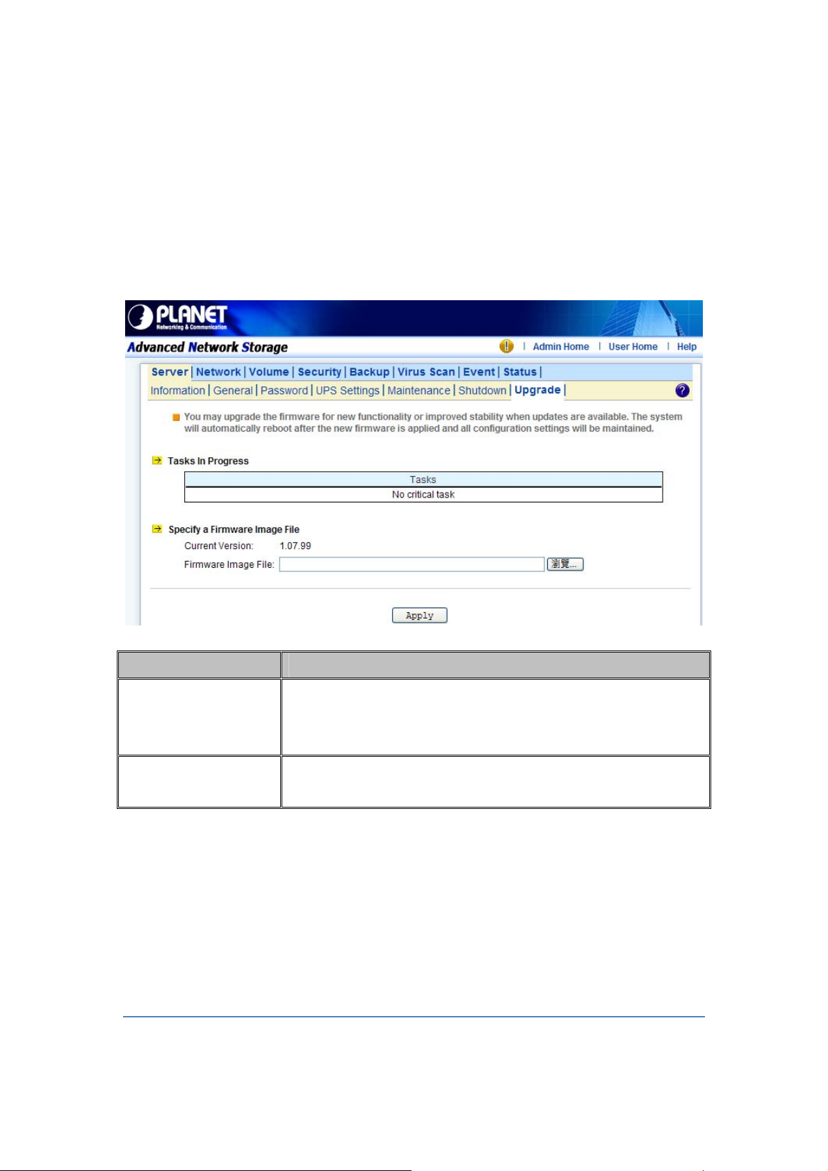
3.2 Upgrading the Firmware
Updating OS firmware will accommodate new functions or bug-fixes. Once you get new
releases of an OS firmware image, you can upgrade the OS firmware by using the web
browser. The process is simple and fast. Once you get the image file of the new OS firmware
from your vendor, open the “Administration Homepage” of the NAS server and select the
“Server → Upgrade” menu. Specify the full path of the image file or click the “Browse” button to
find it. Click “Apply” to begin. The process might take several minutes. The server will reboot
after the firmware is upgraded.
3.3 Shutting Down the Server
20
Page 22
Shutdown, reboot and startup actions
The NAS server can be shut down by pressing the power button twice at the front of the server
case. The whole shutdown process might take seconds to minutes until data are all safely
saved to the hard disks. To shut down the server from the “Administration Homepage”, select
“Shutdown” from the “Server” menu and click the “Reboot” or “Shutdown” button.
You can specify the actions to take during the next startup.
Item Description
Recalculate user
quota information
Reset configuration
to factory default
Scheduled shutdown and power-on
To set the automatic power-on and shutdown schedules, select the “Server → Shutdown”
menu. Click the “Schedule” tab to modify the schedules. On the schedule settings page, you
can set daily or day of month schedules. Check the “Enable” check-boxes and specify the time
of powering on or shutting down. Remember to click the “Apply” button to submit the changes.
Recalculate the storage consumption per user during the next
startup. It may take much time if there are a huge amount of files in
disk.
Reset all configurations to default.
3.4 Enabling UPS Support
The NAS server supports UPS and basic power management functions. It sends alerts when
there are power events like utility power failure or low battery capacity. When power events
21
Page 23

occur, the NAS server can shut down itself automatically to prevent potential data loss.
To use smart-signaling UPS, connect UPS to the NAS server with an RS-232 or USB cable.
Then go to the “Server UPS Settings” menu on the administration page to enable UPS
support.
To use network-type UPS, connect the UPS to the LAN first. Then go to the “Server UPS
Settings” page on the administration page. Enable APC Smart UPS series、 USB UPS、
Generic serial UPS Type 1 and Type 2, select “Network UPS” from the “UPS Type” menu and
enter the UPS IP address and correct community.
Below are the shutdown options on the page.
Item Description
Shut down
Specify whether to shut down the server when UPS battery is low.
immediately when
battery is low
Shut down in x
minutes when AC fails
Turn off UPS when
shut down by power
failure
Specify how many minutes to wait before shutting down the
server when a power event occurs.
If checked, the NAS server will turn off the UPS while it is shutting
down by power failure. If not, the UPS will still be working when
the server is shut down.
22
Page 24

Note:
When utility power fails, the NAS server will always shut down.
23
Page 25

3.5 Modifying the Administrator’s Password
“Admin” is a built-in user account for the administrator. It is like the “root” account in UNIX or
the “administrator” account in Windows 2000 or XP. Using this account, users have access to
the administration homepage and all the storage resources. By default, the password for this
user account is empty. To prevent security vulnerability, it is strongly suggested to specify the
password when performing the first-time setup of the NAS server.
To specify or modify the administrator’s password, please select the “Server → Password”
menu on the administration homepage. Input the current admin password in the “Old Admin
Password” field, and the new password in the “New Admin Password” and “Confirm Admin
Password” fields. Then click “Apply”.
The administrator can delegate the administrator’s privilege to other users by including them
into the Admins built-in group. Please select the “Security → Account” menu. Select “Admins*”
in the “Local User/Group” window and click “Property”. Specify the users to have the privilege
and click “Apply”.
24
Page 26

Chapter 4 Network Configuration
This chapter details concepts and procedures for configuring the NAS server and establishing
the system that can communicate among various OS platforms. Management protocol and
email notification setting are also covered in this chapter.
4.1 Network Information
The “Network Information” screen is the summary of the current network settings of the NAS
server. It provides the administrator a quick look of the basic network setting of the NAS server.
The “Information” page is divided into two sections. The “Network” Protocols section displays
the current network protocol settings of the server.
Item
Protocol Type
Configuration
Security Policy
Display network protocol supported by the server
Current status of the network protocol.
Status: Enabled or Disabled
Display type of the security policy of the network protocol
Description
25
Page 27

The “TCP/IP Suite Settings” section shows the various TCP/IP settings of the server.
Item Description
Port
IP Address
Subnet Mask
Gateway
Speed/Mode
Network Teaming
Mode
Obtain TCP/IP
settings from
WINS Server IP
Display Ethernet port #.
An identifier for a network resource on a TCP/IP network.
A subnet mask used to determine what subnet an IP address
belongs to.
A node on a network that work as a point of entry to another
network
10/100/1000 Mbps and full/half Duplex
Display the current network teaming mode.
Display the IP settings is either assigned automatically from
DHCP or assigned manually
Windows Internet Naming Service (WINS) manages the
association of network resources name and its IP addresses
Address
DNS Server IP
Address
DNS Suffix
NTP Time Server IP
Address
SMTP Server
Address
HTTP Proxy Server
IP Address
without the user or an administrator having to be involved in each
configuration change.
IP address of the domain name system (DNS) server which
located the domain names and translates it into IP addresses.
Display the DNS suffix
The IP address of the NTP (Network Time Protocol) server, which
is used to synchronize system time automatically over the net.
The system time will be synchronized with the NTP server every
24 hours.
IP address or server name of the SMTP (Simple Mail Transfer
Protocol) server used in sending and receiving e-mail.
IP address of the HTTP proxy server. Next to the IP address is the
port number.
26
Page 28

4.2 TCP/IP Settings
TCP/IP handles network communications between network nodes that are connected to the
network. It is important to setting up correct TCP/IP setting that for NAS server to function
properly.
Network Teaming Mode
The NAS server provides two on-board 10/100/1000 or Gigabit Ethernet ports (LAN1 & LAN2).
You can configure the Ethernet ports using the following operating modes:
Stand Alone: Each LAN1 & LAN2 are configured with a unique IP address, which are
independent to each other.
Fault Tolerance: Uses LAN2 to take over for the LAN1 if LAN1 is fail to connect to the network
which designed to ensure server availability to the network.
Load Balancing: Offers increased network bandwidth by allowing transmission to multiple
destination addresses using both LAN1 and LAN2. If the traffic of one of the LAN port starts to
get congested, requests are then forwarded to the other LAN port with more capacity until the
traffic of both LAN ports start to get balance. Note that only the LAN1 Ethernet port receives
incoming traffic.
Load Balancing: also incorporates Fault Tolerance protection.
Link Aggregation: combines both LAN1 & LAN2 into a single channel, appearing to use a
single MAC address to provide greater bandwidth. It must be used with a network switch
having the Link Aggregation or Trucking function.
Wake-On-LAN:
NAS server also supports Wake-On-LAN (available for LAN2 only). Wake-On-LAN allows
administrators to remotely power on your NAS server to perform maintenance task on the
server with no need to go to the server physically.
Configuring TCP/IP Settings
1. Select a “Network Teaming Mode” from the pull-down menu that suit you need.
2. Enable or Disable “Wake On LAN” (Available for LAN2 only).
3. Click the “Obtain IP settings automatically” radio button to obtain IP addresses of your NAS
server from DHCP, BOOP or RARP server on the network.
4. Or, click the “Use the following IP settings” radio button to assign the IP addresses manually.
5. Note that LAN3 IP address field will appear only when the optional Gigabit Ethernet adapter
is installed in your system.
6. Input the “WINS server IP address”.
7. Input the “DNS server IP address”.
8. Input the “DNS Suffix”.
27
Page 29
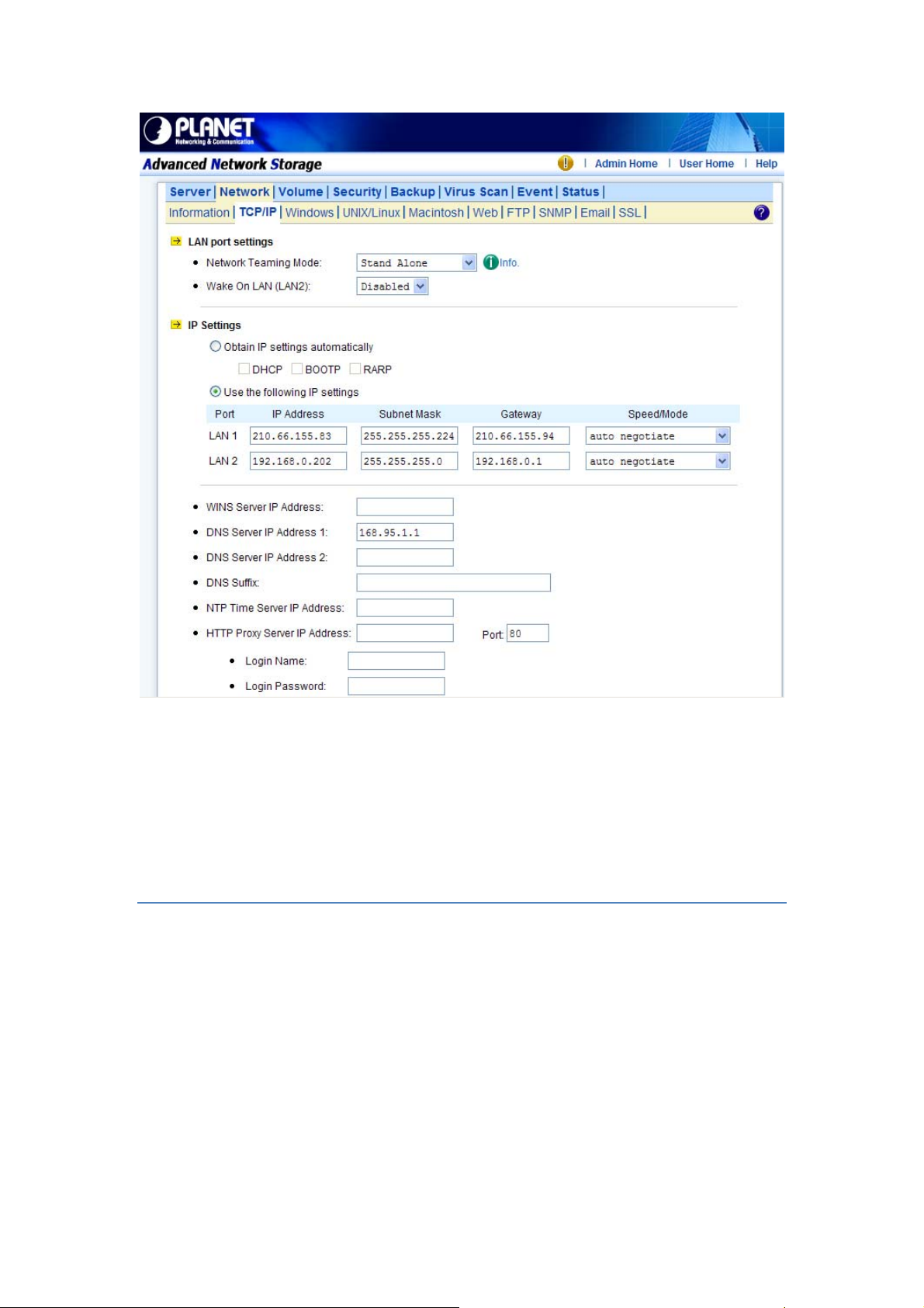
9. Input the “NTP Time Server IP Address” if available.
10. Click “Apply” to save the setting.
To disable a LAN port, enter 0.0.0.0 in its “IP address” field. If you happen to disable all LAN
ports and cannot access the administration page, please use the LCD panel to change the IP
address to non-zero values.
4.3 Windows Settings
NAS server using SMB/CIFS protocol- short for Server Message Block/Common Internet File
System, a protocol used by Microsoft to share files, directories and devices with the Windows
client.
You can configure the Windows Network Settings using the following operating mode:
Workgroup Mode: NAS server becomes a member of a workgroup and communicates with
the clients using its internal user database for authentication and do not require other
authentication server present in the network.
Domain Mode: NAS server become member of a domain and communicates with the client
using the user database stored in an authentication server which must be present in the
network. Optionally, you can register the NAS server to the domain. Once registered, the NAS
28
Page 30

server will be created as a machine account on the domain controller. And it will use Kerberos
as the authentication mechanism, which provides better integration into the Windows network
environment.
Configuring Windows Network Settings
1. Click the “Enable Windows Network” (SMB/CIFS Protocol) checkbox to enable access for
SMB client.
2. Enter the Workgroup/Domain name. Use FQDN if you want to configure
NAS server in Domain Mode Ex: Microsoft.com
3. Click the “Workgroup Mode” radio button if you want to configure NAS server in “Workgroup
Mode”.
4. Or, click the “Domain Mode” radio button if you want to configure NAS server in “Domain
Mode”.
5. Input the domain manager’s user name and password (Power Users at least)
6. Select the option to disconnect idle connection automatically. Server will disconnect the
connections which have been idle for 5 minutes if this option is enabled.
7. Click “Apply” to save the setting.
4.4 UNIX/Linux Settings
NAS server can export shares to UNIX/Linux client via NFS protocol. UNIX/Linux client then
can mount the shares and gain access to the content of the shares. UNIX/Linux client uses
UNIX user identification, typically consisting of User Identifier (UID) and Group Identifier (GID),
for access control. Non-NFS clients do not use UIDs and GIDs for identification. Since NAS
server is intended for working in a heterogeneous network, files created by non-NFS client
could possess incorrect ownership information and generate inaccurate quota information for
UNIX/Linux clients due to the unmatched UID and GID. A mapping is needed to maintain the
correct identity of the user using multiple protocols to access NAS server, for example
Windows and UNIX/Linux clients. Windows based clients need to map the Windows user
name to UID/GID before forwarding a request to retain the correct ownership information for
UNIX/Linux clients. By default, the NAS server maps all non-NFS users, including local users
and domain users, with the same UID/GID as defined on this page. If the administrator wants
to have different UID/GID for different users, he should click the
Modify button to modify the user mapping to UID/GID.
UID: User ID. The numerical number assigned to a user in Unix/Linux permissions. NFS uses
UID to determine permissions on files and directories.
GID: Group ID. A part of POSIX permissions that determine groups of users. NFS files have a
GID assigned to them.
Permission: Three numbers are used for setting the file permission. Each of the three
29
Page 31

numbers corresponds to the type of users- Owner, Members of a group and Everyone Else.
Number Read (R) Write (W) Execute (X)
0 No No No
1 No No Yes
2 No Yes No
3 No Ye s Yes
4 Yes No No
5 Yes N o Ye s
6 Yes Ye s N o
7 Yes Yes Ye s
Example: If the permission of a file is set to 777, this file has read, write and execute
permissions for the owner, the group and for other users.
Configuring UNIX/Linux Network Settings
1. Click the “Enable UNIX/Linux Network” (NFS Protocol) checkbox to enable access for NFS
client.
2. Enter the default permission for files created via non-NFS protocol. (Default setting = 755)
3. Click “Apply” to save the settings.
4. Click the Modify icon and enter the default UID and GID. (Default setting = 0)
5. Choose to map all users to the default UID/GID or assign UID/GID for each user manually.
6. Click “Set Default” link to set the UID/GID of all users to the default UID/GID. Note that the
value ‘-1’ represent that the UID/GID is equal to the default UID/GID configured above.
7. Click “Apply” to save the settings
30
Page 32

Configuring NIS settings
The NIS (network information services), formerly known as Yellow Pages, is a UNIX standard
for centralizing the management of UNIX resources. The NAS server supports the retrieval of
user accounts and their UID/GID from a NIS server.
If the NIS support is enabled, the NAS server cans auto-map NIS users with local/domain
users. It matches user names and assigns the UID/GID of the matched NIS users to
local/domain users. The user auto-mapping function provides better and tighter integration
between NFS clients and other network operating systems.
The steps of enabling NIS support are as follows:
1. Check the “Enable NIS Support” checkbox.
2. The NIS domain name is required. Please fill in the correct name in “NIS Domain Name”
field.
3. If you do not know the IP address of the NIS server, please specify “Find by broadcast”.
Otherwise, specify the IP address in the fields.
4. After enabling the NIS support, you can auto-mapping NIS users with local/domain users. In
“UNIX/Linux” menu, click the “Modify” icon.
5. Select “Map users to UID/GID as defined below” to Apply.
6. Click the “Auto-map with NIS users” link to map with the users in the configured NIS server.
4.5 Macintosh Settings
NAS server supports two kinds of protocols used for Mac OS clients –TCP/IP (Open Transport)
and Both AppleTalk and TCP/IP. Also, NAS server provides two kinds of security polices for
Macintosh Network AFP client.
31
Page 33

Local account authentication: Authenticate user using NAS server’s internal user database.
Local and domain authentication: If Windows Network is enabled, you can enable both local
and domain authentication for AFP client.
Current Zone: A division between groups of machines when viewed using AppleTalk.
AppleTalk Zones can be seen in the Chooser, the AppleTalk Control Panel, and the Network
Browser.
AppleTalk Address: It is a unique number that identify the server on the network. The number
to the left of the dot is the network number. The number to the right of the dot is the node
number.
32
Page 34

Configuring Macintosh Network Settings
1. Click the “Enable Macintosh Network” (AFP Protocol) checkbox to enable access for AFP
client.
2. Select a protocol and click the radio button beside it.
3. Click the “Local account authentication” radio button to authenticate user using the server’s
local user database.
4. Or, click the “Local and domain account authentication” radio button to use both local
account and Microsoft domain security authentication.
5. Select the “Current Zone” from the pull down menu or “Default Zone” is assigned by default.
6. Click “Apply” to save the setting.
4.6 Web Data Access Settings
This section shows the parameters that you can set up for user to access NAS system user’s
home page. You can configure the user access constraint, authentication policy and default
setting by defining the “Access Control”, “Security Policy” and “Default User Page” settings.
Configuring Web Data Access
1. Click the “Enable Web Data Access” (HTTP Protocol) checkbox to enable Web data
accessing.
2. Choose “Allow file download only” or “Allow file upload and download”.
3. Click the “Local account authentication” radio button to authenticate user using the server’s
local user database.
33
Page 35

4. Or, click the “Local and domain account authentication” radio button to use both local
account and Microsoft domain security authentication.
5. Select the default type of the folder display on the user page. You can choose from “Detail
View”, “Large Icons” or “Small Icons”.
6. Click the checkbox beside the “Allow users to modify ACL” to give users the privilege to
modify the ACL table entries.
7. Click “Apply” to save the setting.
4.7 FTP Data Access Settings
NAS system supports File Transfer Protocol (FTP) that allows users to transfer files via the
Internet. By properly configuring the FTP settings, you can effectively control how users
access the content in your NAS server via FTP.
Configuring FTP Data Access
1. Click the “Enable FTP Data Access” checkbox to enable FTP data accessing.
2. Select the “Access” Control type. Click the “Allow file download only” or “Allow file upload
and download” radio button.
3. Select the appropriate “Security Policy”. Check the “Allow anonymous login and map to”:
check-box, and select a local user from the pull down menu. User using the anonymous
login will then possess the same security privilege as the selected local user.
34
Page 36

4. Or, click “Allow individual user login”. Select “Local account authentication” to authenticate
user using the local user database or click the “Local and domain account authentication”
radio button to use both local account and Microsoft domain security authentication.
5. Select the “User Limit”. Click the “Unlimited” radio button or specify the maximum number of
users allowed to access the content in your NAS server via FTP.
6. Specify the “Home Directory” when user connects to the NAS server via FTP. Note that you
must select a volume to create a FTP home directory.
7. Specify the permission of the home directory by clicking the “Set” icon.
8. Click “Apply” to save the setting.
4.8 SNMP Settings
Simple network management protocol (SNMP) provides the ability to monitor and gives status
information of the SNMP agent to the SNMP management console. NAS server behaves as an
SNMP agent that answers requests from management console and sends trap information to it.
The following options should be configured to using SNMP protocol:
Community: A name serves as a simple authentication. The communication between the
SNMP management console and the NAS server cannot be established if the community
names are mismatch.
IP: IP address of the SNMP management console
Trap: A trap is a voluntary message send out from a SNMP agent (which is in this case your
NAS server) when there is an event occurred.
Management: Configure the SNMP management console as Read Only or Full Control.
Location: Provide location information of the SNMP agent.
35
Page 37

Contact: Provide name of the contact person who has the management information of the
SNMP agent.
Configuring SNMP Settings
1. Click the “Enable SNMP Protocol” checkbox to enable SNMP accessing.
2. Enter a “Community” name.
3. Enter the “IP” address of the management console.
4. Select “Yes” from the pull down menu if you want the corresponding management console
to receive trap message.
5. Select “Read Only” from the pull down menu if you want the corresponding management
console has read only privilege.
6. Repeat Step 2 to Step 5 if more than one management console is available. NAS server
supports up to 4 management consoles.
7. Enter the location information of your NAS server.
8. Enter the name of the contact person who has the management information of the NAS
server.
9. You can check the checkbox beside “Send a test trap” to send sample trap information to
validate your setting of the SNMP settings.
10. Click “Apply” to save the setting.
4.9 Email Settings
You can configure email notification to notify you when there is an event occurred to the NAS
server. Enter the information of the SMTP server on your network in this menu; you can
configure what kind of event should trigger the email notification process in the “Event →
Configuration → Advance” menu.
36
Page 38

Configuring Email Settings
1. Click the “Enable SMTP Protocol” checkbox to enable SMTP protocol.
2. Enter the “SMTP Server Address”.
3. Enter an existing user account name of the SMTP server.
4. Enter the password of the account.
5. Enter up to two email addresses you want to send email notification to when event occurred.
6. Click the “Send a test email” checkbox if you want to send out a test email to validate your
email setting.
7. Click “Apply” to save the setting.
37
Page 39

4.10 SSL Settings
The NAS server enables secure web access by supporting SSL 3.0, both for the user
homepage and the administration homepage. To use SSL 3.0, the NAS server will generate a
server certificate for authentication and data encryption. By default, the server certificate is
issued to the NAS server designated by its IP address. You can also specify to use the server's
full name on the server certificate.
For clients to access server web-pages with secure connection, they have to install the CA
certificate first. First of to the “Network → SSL” page. Click
“Download and install CA certificate“ hyperlink. Ch
dialog-box pops up. Once the CA certificate is installed, the client can access all NAS server s'
web pages with SSL connection. Suppose that the server IP address is 192.168.1.100. To
access the NAS system's web pages with SSL connection, please open https://192.168.1.100/
for the user homepage, or https://192.168.1.100/admin/ for the administration homepage. If the
server certificate with the server name is chosen, please open https://[server_name] instead.
oose to install the certificate when a
38
 Loading...