

Page 1
4-Bay SATA NAS RAID Server
with iSCSI
NAS-7410
1
Page 2

4-Bay SATA NAS RAID Server with iSCSI
NAS-7410
Copyright
Copyright © 2013 by PLANET Technology Corp. All rights reserved. No part of this
publication may be reproduced, transmitted, transcribed, stored in a retrieval system, or
translated into any language or computer language, i n any form or by any mean s, electroni c,
mechanical, magnetic, optical, chemical, manual or otherwise, without the prior written
permission of PLANET.
PLANET makes no representations or warranties, either expressed or implied, with respect
to the contents hereof and specifically disclaims any warranties, merchant ability or fitness for
any particular purpose. Any software described in this manual is sold or licensed "as is".
Should the programs prove defective following their purchase, the buyer (and not PLANET,
its distributor, or its dealer) assumes the entire cost of all necessary s ervicing, repair, and
any incidental or consequential damages resulting from any defect in the software. Further,
PLANET reserves the right to revise this publication and to make changes from time to time
in the contents hereof without obligation to notify any person of such revision or changes.
All brand and product names mentioned in this manual are trademarks and/or registered
trademarks of their respective holders.
CE mark Warning
This is a class A device, in a domestic environment; this product may cause radio interference, in which
case the user may be required to take adequate measures.
Federal Communication Commission Interference Statement
This equipment has been tested and found to comply with the limits for a Class A digital
device, pursuant to Part 15 of FCC Rules. These limits are designed to provide reasonable
protection against harmful interference in a residential installation. This equipment generates ,
uses, and can radiate radio frequency energy and, if not installed and used in accordance
with the instructions, may cause harmful interference to radio communications. However,
there is no guarantee that interference will not occur in a particular installation. If this
equipment does cause harmful interference to radio or television reception, which can be
determined by turning the equipment off and on, the user is encouraged to try to correct the
interference by one or more of the following measures:
1. Reorient or relocate the receiving antenna.
2. Increase the separation between the equipment and receiver.
3. Connect the equipment into an outlet on a circuit different fro m that to which the receive r is
connected.
4. Consult the dealer or an experienced radio technician for help.
FCC Caution:
To assure continued compliance (example-use only shielded interface cables when
connecting to computer or peripheral devices). Any changes or modifications not expressly
approved by the party responsible for compliance could void the user’s authority to operate
the equipment.
This device complies with Part 15 of the FCC Rules. Operation is subject to the Following
two conditions: (1) This device may not cause harmful interference, and (2) thi s Device must
accept any interference received, including interference that may cause undesired
operation.
Safety
This equipment is designed with the utmost care for the safety of those who in stall and u se it.
However, sp ecial attentio n must be paid to the dangers of electric shock and static electricity
when working with electrical equipment. All guidelines of this and of the computer
manufacture must therefore be allowed at all times to ensure the safe use of the equipment
.
2
Page 3

4-Bay SATA NAS RAID Server with iSCSI
NAS-7410
CE Mark Warning
This is a Class B product. In a domestic environment, this product may cause radio
interference, in which case the user may be required to take adequate measures.
WEEE Regulation
To avoid the potential effects on the environment and human health as a result of
the presence of hazardous substances in electrical and electronic equipment, en d
users of electrical and electronic equipment should understand the meaning of
the crossed-out wheeled bin symbol. Do not dispose of WEEE as unsorted
municipal waste; they should be collected separately.
Revision
User’s Manual for PLANET 4-Bay SATA NAS RAID SERVER with iSCSI
Model: NAS-7410
Rev: 1.00 (June.2013)
Part No. EM-NAS-7410
3
Page 4

4-Bay SATA NAS RAID Server with iSCSI
NAS-7410
Table of Contents
Chapter 1. Product Introduction.................................................................................... 6
1.1. Package Contents ............................................................................................ 6
1.2. Overview ............................................................................................................ 6
1.3. Features........................................................................................................... 10
1.4. Product Specifications ................................................................................... 10
Chapter 2. Hardware Interface .................................................................................... 13
2.1 Physical Descriptions...................................................................................... 13
2.1.1 Front Panel............................................................................................ 13
2.1.2 Real Panel............................................................................................. 14
2.2 Hardware Installation ...................................................................................... 15
2.3 Initial Utility Installation ...................................................................................18
Chapter 3. Server Configuration.................................................................................. 21
3.1. Server Information.......................................................................................... 21
3.2 General.............................................................................................................. 22
3.3 Modifying the administrator’s password....................................................... 22
3.4 Enabling UPS support ....................................................................................23
3.5 Shutting down the server................................................................................ 24
3.6 Upgrading the firmware .................................................................................. 26
Chapter 4. Network Configuration ............................................................................... 27
4.1 Network Information ........................................................................................ 27
4.2 TCP/IP settings ................................................................................................ 28
4.3 Windows settings............................................................................................. 30
4.4 UNIX/Linux settings......................................................................................... 31
4.5 Macintosh settings........................................................................................... 33
4.6 Web data access settings .............................................................................. 34
4.7 FTP data access settings............................................................................... 35
4.8 SNMP settings ................................................................................................. 37
4.9 Email settings................................................................................................... 38
4.10 SSL settings ................................................................................................... 39
4.11 IPv6 .................................................................................................................. 39
Chapter 5. Vo
5.1 Volume Information ......................................................................................... 41
5.2 Creating a volume ........................................................................................... 43
5.3 Deleting a volume............................................................................................ 45
5.4 Expanding a RAID-5 volume ......................................................................... 46
5.5 Migrating Data Volumes ................................................................................. 46
5.6 Volume/Disk scan ............................................................................................ 47
5.7 iSCSI (IP SAN)................................................................................................. 48
5.8 Recycle bin ....................................................................................................... 50
Chapter 6. Security control ........................................................................................... 51
6.1 Security information......................................................................................... 51
6.2 Creating share and assigning share permissions ...................................... 52
6.3 Configuring file and folder security and ACL............................................... 56
6.4 Creating the local user and local group accounts ......................................
lume Configuration ................................................................................ 41
59
4
Page 5

4-Bay SATA NAS RAID Server with iSCSI
NAS-7410
6.5 Caching windows domain user accounts..................................................... 62
6.6 Creating UNIX/Linux host............................................................................... 63
6.7 Managing quotas ............................................................................................. 64
Chapter 7. Disc Sharing and Data
Archiving ............................................................. 66
7.1 Starting to use the disc server function ........................................................ 66
7.2 Sharing discs.................................................................................................... 67
7.3 Creating disc images....................................................................................... 69
7.4 Managing discs ................................................................................................ 71
7.5 Burning disc images........................................................................................ 72
7.6 Archiving data to CD/DVD discs.................................................................... 73
Chapter 8. User access.................................................................................................
75
8.1 Workgroup or domain mode .......................................................................... 75
8.2 Accessing from windows ................................................................................ 76
8.3 Accessing from web browsers....................................................................... 76
8.4 Accessing from MacOS .................................................................................. 78
8.5 Accessing from FTP clients............................................................................ 80
8.6 Accessing from NFS clients ...........................................................................81
Chapter 9. Backup and Recovery ...............................................................................83
9.1 Snapshot – Fast Point-In-Time copies ......................................................... 83
9.2 SmartSync – NAS-to-NAS data replication ................................................. 84
9.4 Backup and restore system profiles ............................................................. 90
9.5 Backup USB device ........................................................................................92
Chapter 10. Virus Protection ........................................................................................ 93
10.1 Information...................................................................................................... 93
10.2 Real-time, manual and schedule scanning ............................................... 94
10.3 Configuring scan settings............................................................................. 95
10.4 Updating virus pattern file ............................................................................ 96
Chapter 11. Event Logs ................................................................................................ 97
11.1 Event and Thermal settings .........................................................................97
11.2 Checking the event logs ...............................................................................98
Chapter 12. System Status...........................................................................................
98
12.1 Viewing system status .................................................................................. 98
12.2 Saving system settings and status as HTML files.................................. 100
12.3 Share access counts................................................................................... 101
Appendix A Hot-swapping ........................................................................................... 102
Appendix B Utility for NAS system ............................................................................ 103
Appendix C Troubleshooting & Frequently Asked
Questions ............................... 118
5
Page 6
4-Bay SATA NAS RAID Server with iSCSI
NAS-7410
Chapter 1. Product Introduction
1.1. Package Contents
The package should contain the following items:
z NAS-7410 x 1
z HDD Key x 4
z Power Cord x 1
z 2.5 inch HDD Screw x 16
z 3.5 inch HDD Screw x 12
z Console Connector x 1
z User’s Manual CD x 1
z Quick Installation Guide x 1
1. If any of the above items are missing, please contact your dealer immediately.
2. Using the power supply that is not included in the package will cause damage, thus
voiding the warranty for this product.
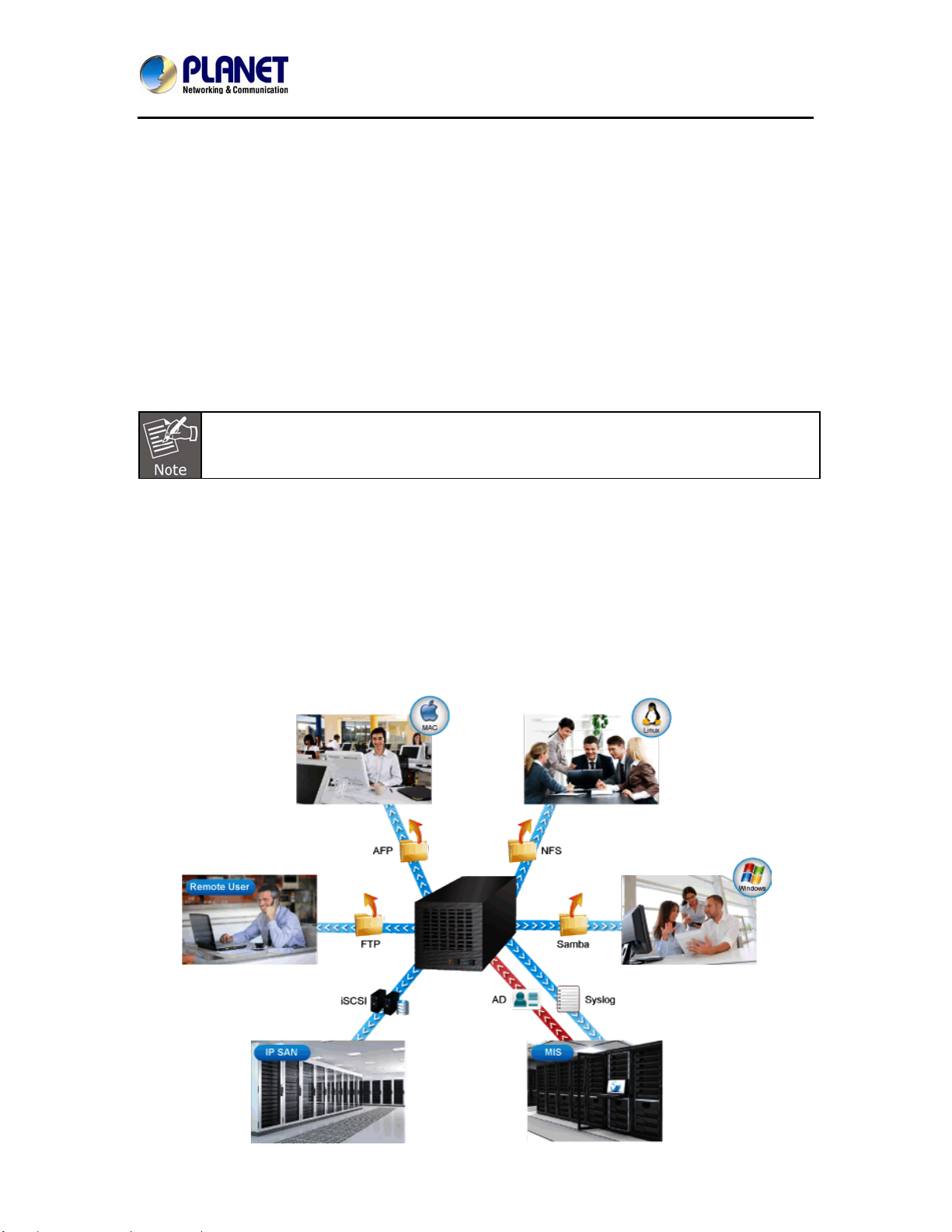
1.2. Overview
High Performance Shared Storage Server
PLANET NAS-7410, a reliable and high-performance business-class network storage is a 4-bay
RAID network storage system for those seeking reliable and affordable server virtualization and
file storage. The network storage unified architecture supports both NAS and IP-SAN applications
and solves numerous data management problems with a single system. Support for major network
file-system protocols enables cross-platform compatibility and file sharing among Windows, Mac
and Unix/Linux operating systems. Integrated data protection and offsite replication features make
managing complex business storage environments affordable.
6
Page 7
4-Bay SATA NAS RAID Server with iSCSI
NAS-7410
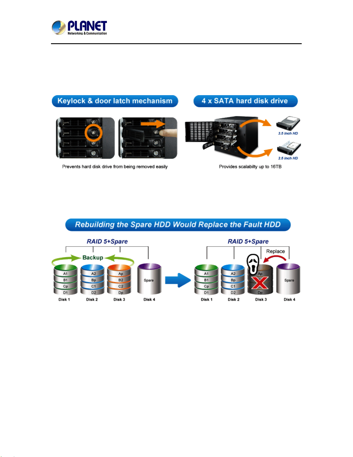
Space Saving & Tray-less Design
The NAS-7410 is designed to allow the installation of up to four 2.5”/3.5” SATA hard drives. Each
hard drive door has a multi-locking latch mechanism in order to prevent a door from being opened
easily. Each of these doors includes a tray and hard drive key that can be easily unlocked and
pulled out. Then users can easily attach the hard drive to the hot-swap hard drive tray with the
screws.
Auto
matic Data Protection by RAID & Hot Swap
The NAS-7410 provides advanced RAID configurations including RAID 0, 1, 5, 6 and 10 functions.
You can get the perfect compromise between speed and disk-failure proof, hardware-level data
protection. It also supports hot-swap design so that a failed drive can be replaced by hot swapping
without turning off the server.
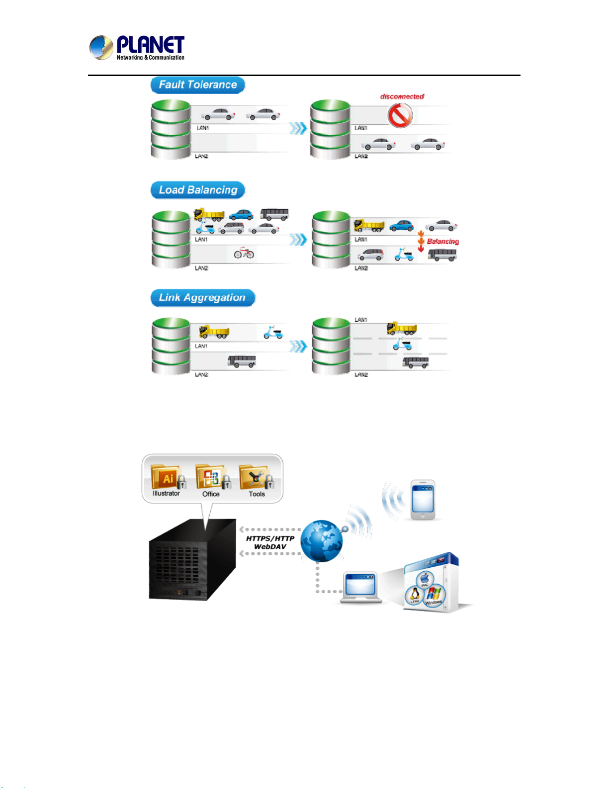
Multiple LAN for Better Efficiency
The NAS-7410 features multiple functions to support LAN storage for better efficiency.
Fault Tolerance:When LAN1 of the NAS-7410 fails to connect to the network, LAN2 would take
over from LAN1 which is designed to ensure server availability to the network.
Load Balancing:When the traffic of LAN1 starts to get congested, then LAN2 would share the
traffic until the traffic of both LAN ports starts to get balanced. Load Balancing also incorporates
Fault Tolerance protection.
Link Aggregation:Combine LAN1 and LAN2 into a single channel to provide greater bandwidth.
Must be used with Link Aggregation switch.
7
Page 8
4-Bay SATA NAS RAID Server with iSCSI
NAS-7410
The Extension of Network Communication by WebDAV
The NAS-7410 supports WebDAV, which is an extension of the HTTP protocol for users to edit
and manage documents and files that are stored on servers over the Internet. It also allows iOS
and Android WebDAV clients to access files from NAS server.
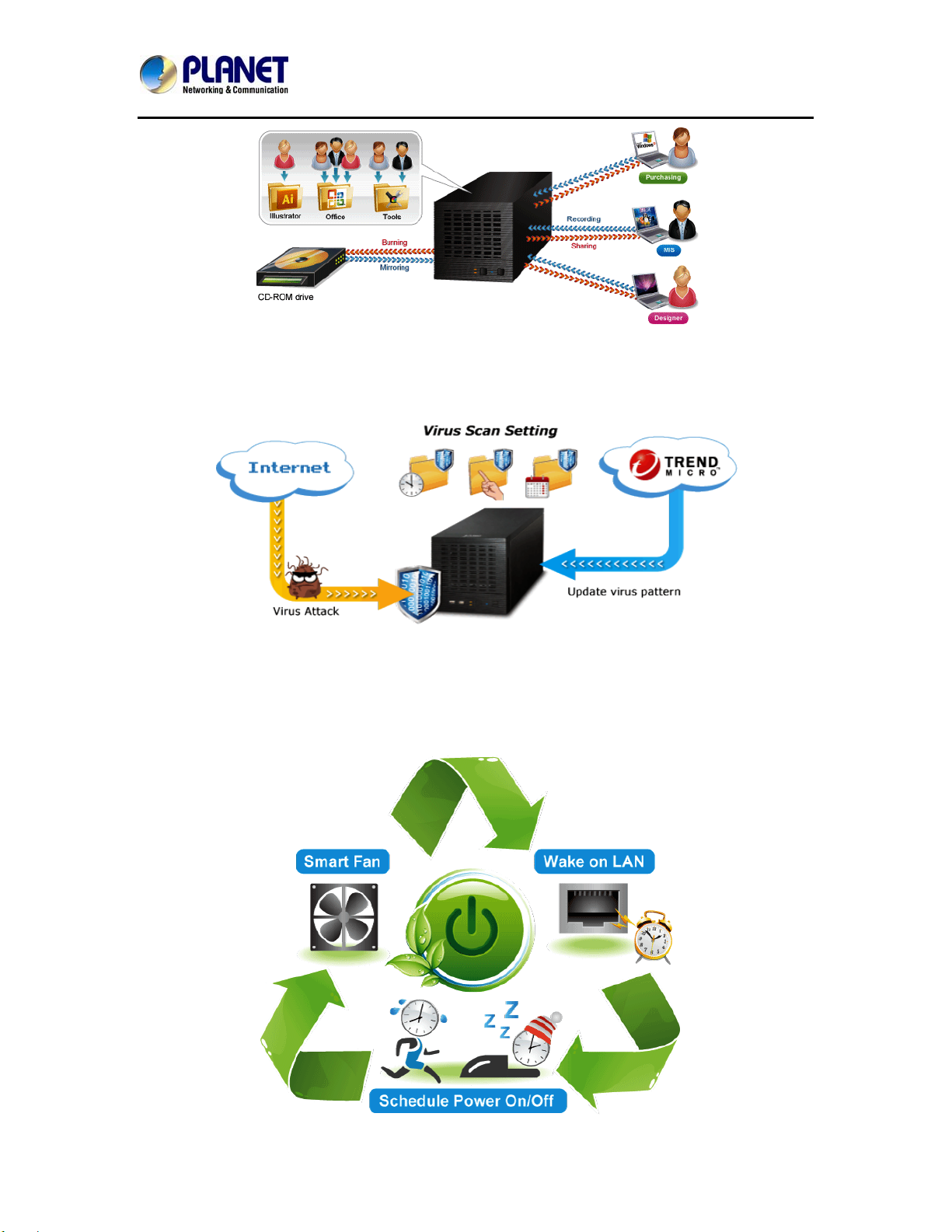
erful Disc Images Management and Sharing by Disc Server
Pow
Disc Server is our unique technology which is designed for CD/ DVD, Blu-ray disc images creation,
burning and data archiving for central management. This feature saves the space for storing the
physical discs, reduces the risk of data loss caused by disc wearing and tearing, and enhances the
efficiency of data sharing on business network.
8
Page 9
4-Bay SATA NAS RAID Server with iSCSI
NAS-7410
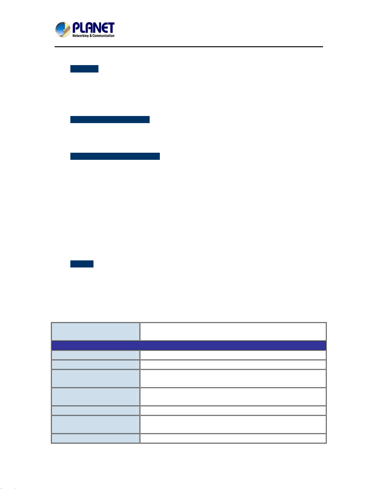
Always
-on Data Security with Trend Micro
The NAS-7410 features virus engine scanning technology and cooperates with well-known Trend
Micro Anti-virus Company. It updates the virus pattern information automatically via internet to
protect NAS against new virus attacks. The real-time online scanning can warn and remove
infected files to prevent users from distributing virus from NAS on the network.
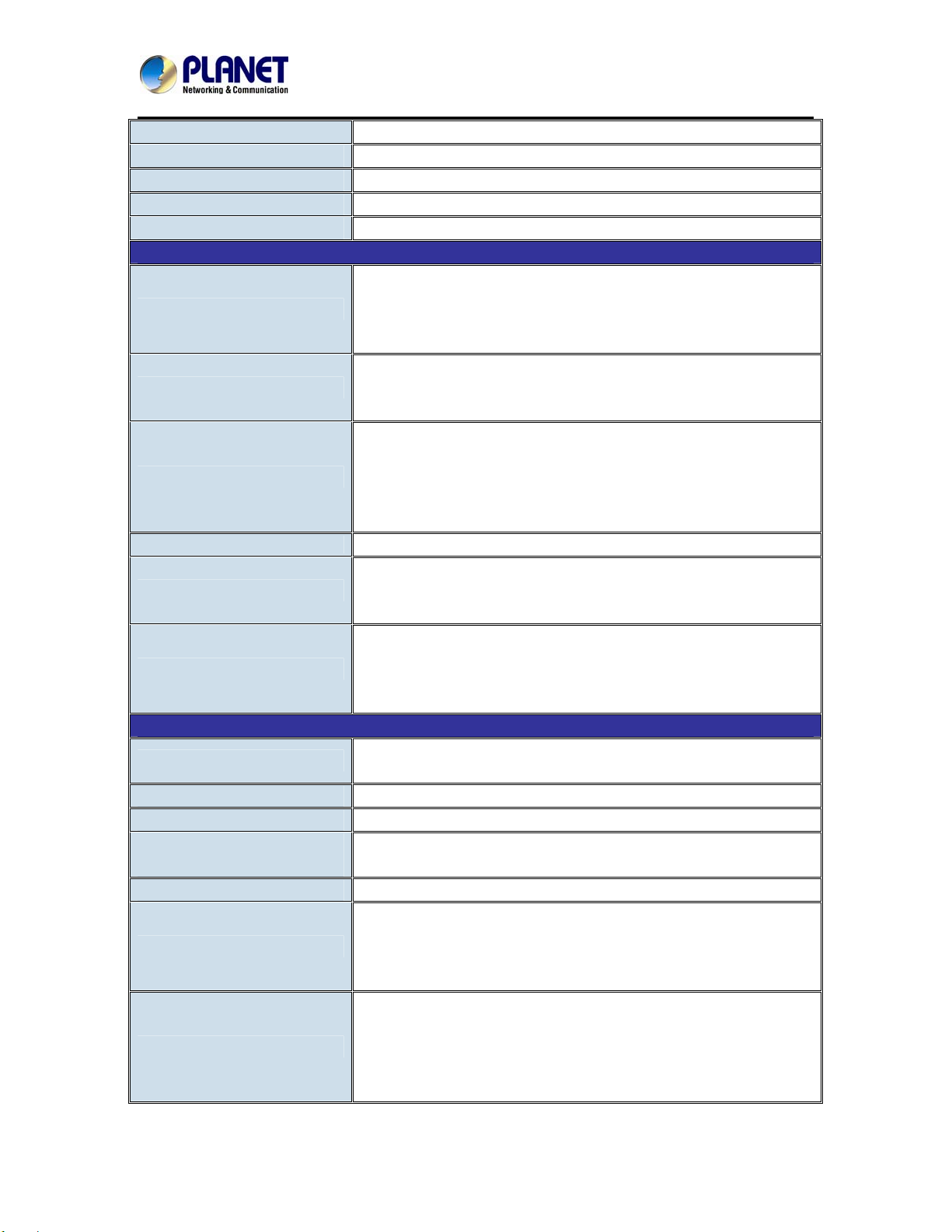
Energy Efficient Design
The NAS-7410 feature
s green technologies to protect the environment and save electricity. The
smart fan monitors the system temperature of the NAS-7410 and automatically adjusts its speed
to ensure quiet operation and power saving. Scheduled power on/off feature provides flexibility to
only allow the NAS-7410 to operate in designated time and therefore minimize power usage. The
NAS-7410 can be powered on remotely and reduce the power consumption by Wake on LAN.
9
Page 10
4-Bay SATA NAS RAID Server with iSCSI
NAS-7410
1.3. Features
¾ Hardware
High performance Intel Dual Core 1.8GHz processor
Provides scalability up to 16TB (with 4TB per hard drive)
Tray-less design for genuine plug & play and hot swap use
Integrated dual Gigabit LAN with Fault Tolerance and Link Aggregation
Adds storage capacity by connecting external USB / E-SATA hard disk drives
¾ Network and Configuration
Compatible with Windows 2003 / 2008 / XP / Vista / 7, Mac OS 8.x or above, Linux / Unix
Supports CIFS/SMB to allow Microsoft network remote users to easily retrieve files
Supports VMware vSphere and Citrix XenServe at Server Virtualization & Clustering
¾ Data Backup and Management
Linux based Samba OS provides EXT3 file system for securing data storage
Supports RAID 0, 1, 5, 6, 10 and JBOD
Bad Block Scan & hard drive by S.M.A.R.T.
Supports NAS and iSCSI / IP-SAN for database and server virtualization applications
Built-in FTP server allows users to conveniently transfer files
Allows the administrator to allocate the amount of available disk space to individual users
Provides password protected data access to all users
Supports up to 2048 user accounts with individual access rights
SmartSync backup for automatic client backup
Snapshot for instant backup and restoration
NAS to NAS replication for remote backup
WebDAV enables viewing, adding, or deleting files from the web
Instant Alert via Email, Buzzer, Trap, Web Reminder
¾ General
Antivirus engine protection by Trend Micro
Uninterruptible power supply (UPS) supports without data loss in the case of power failure
Power Saving -- Wake on LAN, Scheduled Power On/Off, Smart-Fan
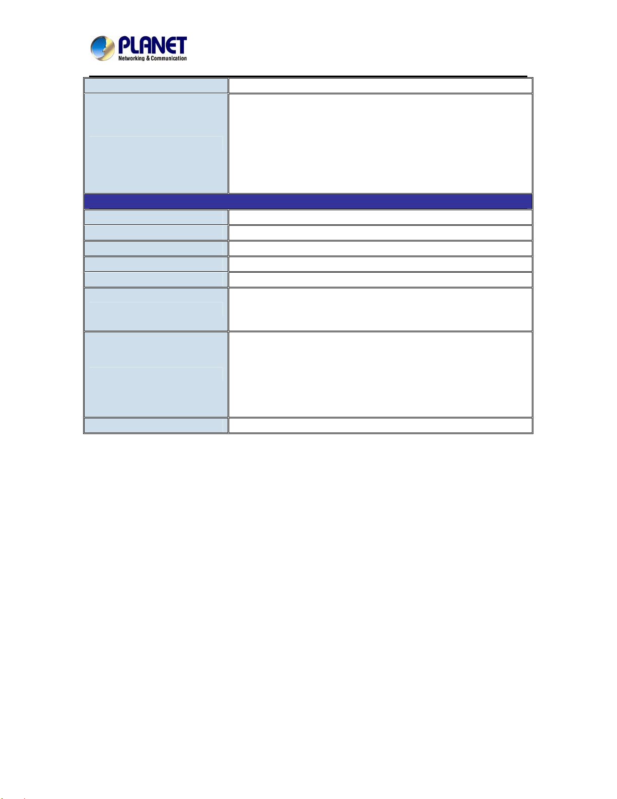
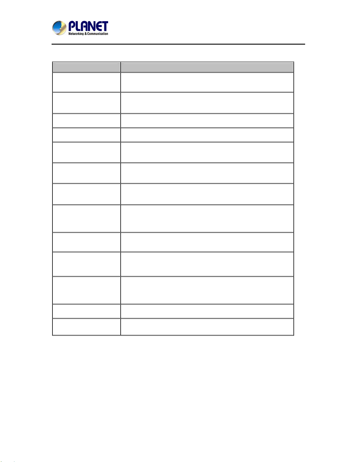
1.4. Product Specifications
Model
Hardware Platform
CPU Frequency Intel D525 1.8GHZ
Memory DDR3 2GB
Supported hard drive
Buttons
LAN Interface 2 x Gigabit Ethernet port with load balancing and fault tolerance
USB Interface
E-SATA Interface 1 x E-SATA port for external storage
NAS-7410
4-Bay SATA NAS RAID SERVER with iSCSI
4 x 2.5”/3.5" SATA I/II/III hard drive (Hard drive not included)
File System: EXT3
1 x Power button
1 x Reset button
6 x USB2.0 port for external storage and UPS
File System: FAT16/32, NTFS
10
Page 11
4-Bay SATA NAS RAID Server with iSCSI
NAS-7410
File system: FAT16/32, NTFS
COM Interface 1 x COM port for UPS
Fan 1 x quiet cooling fan (12 cm, 12V DC, Max. 15400rpm)
Alarm Buzzer System warning
Secure Design Lock security slot for Hard drive prevention
Network and Configuration
IEEE 802.3 10Base-T
Network Standard
Protocol
Security
Supported Languages
Supported Browsers
Supported Clients
IEEE 802.3u 100Base-TX
IEEE 802.3ab 1000Base-T
IEEE 802.3ad for dual link aggregation
IPv4 & IPv6, AppleTalk
HTTPS, CIFS/SMB, AFP, NFS(v3/v4), FTP, FTPS (SSL, TLS),
SSH, SMTP, SNMP, NTP, iSCSI
Password protection
IP address filtering
HTTPS encrypted data transmission
802.1X Port-based authentication for network protection
QoS / DSCP
Unicode UTF-8
Microsoft Internet Explorer 8, 9, 10
Google Chrome
Firefox
Windows XP, Vista, Windows 7 (32-/64-bit),
Windows Server 2003/2008 R2
Apple Mac OS 8.X / 9.X / 10.6X
Linux & UNIX
Data Backup and Management
RAID level
Max. User/ Groups 2048 (including local/domain account/groups)
Max. Shared Folder 256
Max. Concurrent
Connections
Max. iSCSI Target/LUNs 8
Disk Management
Backup Solution
Single Disk, JBOD, RAID 0, 1, 1 + Hot Spare,
5, 5 + Hot Spare, 6, 6 + Hot Spare, 10, 10 + Hot Spare
150
Bad Block Scan & hard drive S.M.A.R.T.
Global hot spare drive
RAID Recovery
BSR (Bad Sector Remap)
SmartSync: NAS-to-NAS, NAS-to-USB/E-SATA,
USB/E-SATA-to-NAS
Snapshot: Point-in-time Copy in a Flash
System Profile: Recover from system failures
Disc Server: Optical disc recording
11
Page 12
4-Bay SATA NAS RAID Server with iSCSI
NAS-7410
Data Backup to Multiple External Storage Devices
Network Access:SSH, HTTPS, FTP, CIFS/SMB, AFP
Encrypted Access: HTTPS, FTP with SSL/TLS, SSH/SFTP,
Encrypted Remote Replication between NAS Servers
Security
Built-in Trend Micro antivirus software
Access Control List (ACL)
Secure Sockets Layer (SSL) 128-bit encryption
Instant alert via email, buzzer, trap, web reminder
General
Power Requirements 100~240V AC, 3.5A, 50~60Hz
Operating Temperature 0 ~ 40 degrees C
Operating Humidity 10 ~ 80% (non-condensing)
Weight 5.1Kg
Dimensions (W x D x H) 200 x 320 x 210 mm
Wake on LAN
Power Management
Antivirus
Emission CE, FCC
Scheduled Power On/Off
COM Port, USB and Network UPS Support
Protection against the latest known viruses, Trojans, and other
threats
Virus pattern update on manual or scheduled basis
Email notification upon task completion or virus detection
Quarantines or deletes infected files
Real-time and scheduled scan setting
12
Page 13

4-Bay SATA NAS RAID Server with iSCSI
NAS-7410
Chapter 2. Hardware Interface
2.1 Physical Descriptions
2.1.1 Front Panel
Interface Description
Power Button Press the button to start the NAS
Reset Button This button is used to restore all the factory default settings
USB Socket
Connects to UPS and external HDD(FAT/FAT32/NTFS)
LED Color
Power
HDD Activity
Blue
Red HDD is being accessed
On: Power on
Off: Power off
Description
13
Page 14

4-Bay SATA NAS RAID Server with iSCSI
NAS-7410
2.1.2 Real Panel
Interface Description
Power Jack
E-SATA
COM
LAN Jack (LAN1)
LAN Jack (LAN2)
USB Socket
VGA
Service
Connect the two power supply cords shipped with the system
Connect to external hard drive case
Connect to UPS
These RJ-45 ports support auto negotiating Gigabit Ethernet
interface. That allows your system to be connected to an
Internet Access device, e.g. router, cable modem, or ADSL
modem over a CAT.5 twisted pair Ethernet cable.
Connect to UPS and external HDD(FAT/FAT32/NTFS)
Future Feature
Future Feature
14
Page 15

4-Bay SATA NAS RAID Server with iSCSI
NAS-7410
2.2 Hardware Installation
2.2.1 Installing the Hard Disk Drive
1. Release the HDD tray by pulling the lock to the right.
2. Pull the HDD tray out of the case.
3. Place the HDD in the tray by unscrewing and screwing it.
15
Page 16

4-Bay SATA NAS RAID Server with iSCSI
NAS-7410
4. Put the HDD tray back to the case.
5. Push the tray door back to the case to secure it.
2.2.2. Network Installation
The NAS-7410 provides GUI (Web based, Graphical User Interface) for management and
administration. The default IP address of NAS server is 192.168.0.100. You may now open your
web browser, and insert http://192.168.0.100 in the address bar of your web browser to login web
configuration page. The NAS server will prompt for login username / password. Please enter:
admin / admin to continue the NAS Server administration.
16
Page 17

4-Bay SATA NAS RAID Server with iSCSI
NAS-7410
Default DHCP Client
Default IP Address 192.168.0.100
Default Login User Name admin
Default Login Password admin
Search Tools
If the networked device’s default IP Address (192.168.0.100) is already used
by another device, the other device must be turned off until the device is
allocated a new IP Address during configuration.
OFF
NAS Finder
17
Page 18

4-Bay SATA NAS RAID Server with iSCSI
NAS-7410
2.3 Initial Utility Installation
This chapter shows how to quickly set up your NAS system. The NAS is with the default settings.
However to help you find the networked NAS quickly the windows utility PLANET NAS Finder can
search the NAS in the network that will help you to configure some basic setting before you start
advanced management and monitoring.
Configuring the IP addresses using NAS Finder
The utility is designed to perform a quick setup and put your NAS server online in just a few
minutes. During startup, NAS Finder begins to discover the entire NAS server on the network. The
default server name would be NAS-7410.
1. Highlight the server you want to configure from the left hand pane.
2. Click the setting button on the toolbar.
18
Page 19

4-Bay SATA NAS RAID Server with iSCSI
NAS-7410
3. The default is Assign an IP address manually. If you want IP settings to be assigned
automatically, click Obtain IP settings automatically.
19
Page 20

4-Bay SATA NAS RAID Server with iSCSI
NAS-7410
4. Enter the Server Name, Server Comment, and Workgroup/Domain Name and select either
the Workgroup mode or Domain mode.
6. Change the admin password if necessary.
7. Click the OK button to save the settings.
20
Page 21

4-Bay SATA NAS RAID Server with iSCSI
NAS-7410
Chapter 3. Server Configuration
This chapter describes how to name the server, specify the server date and time, upgrade the OS
firmware, shut down the system and use UPS with the NAS server.
3.1. Server Information
Click Server from the administration homepage. You will see the Information page describing the
summary information of the NAS server.
Item
Server Name
Server Comment
Date/Time Server date and time in 24-hour format.
Time Zone
UPS Support Indicates whether the UPS support is enabled or not.
System Folder
resides in
Name of the NAS server. A NAS server has one unique name,
applicable to all network protocols.
The text which is shown in the comment field when browsing
network computers in Windows Network Neighborhood.
The time zone setting of the server relative to the Greenwich
standard time.
Display the volume name in which the system folder is located.
Description
21
Page 22

4-Bay SATA NAS RAID Server with iSCSI
NAS-7410
The System Information section shows the hardware and firmware status of the server.
Item Description
Firmware Version
Processor Type
Memory Capacity
No. of HDD/CD/tape
LAN1/2 Ethernet
Address
PCI-E Slot
The version number of the OS firmware.
The CPU operating frequency.
The total size of the main memory.
Display the number of HDD/CD/tape installed in the system.
The Ethernet MAC addresses of the network controller chips and
their types.
Display the type of the add-on adaptor installed in the system.
The NAS-7410 cannot support this function.
3.2 General
The General Settings section shows the parameters which can be modified on the
Server→General page.
3.3 Modifying the administrator’s password
Admin is a built-in user account for the administrator. It is like the root account in UNIX or the
administrator account in Windows 2000 or XP. Using this account, users have access to the
administration homepage and all the storage resources. By default, the password for this user
account is empty. To prevent security vulnerability, it is strongly suggested to specify the password
when performing the first-time setup of the NAS server.
To specify or modify the administrator’s password, please select the Server→Password menu on
the administration homepage. Input the current admin password in the Old Admin Password field,
and the new password in the New Admin Password and Confirm Admin Password fields. Then
click Apply.
22
Page 23

4-Bay SATA NAS RAID Server with iSCSI
NAS-7410
The administrator can delegate the administrator’s privilege to other users by including them into
the Admins built-in group. Please select the Security→Account menu. Select Admins* in the
Local User/Group window and click Property. Specify the users to have the privilege and click
Apply.
3.4 Enabling UPS support
The NAS server supports UPS and basic power management functions. It sends alerts when there
are power events like utility power failure or low battery capacity. When power events occur, the
NAS server can shut down itself automatically to prevent potential data loss.
To use smart-signaling UPS, connect UPS to the NAS server with an RS-232 or USB cable. Then
go to the Server UPS Settings menu on the administration page to enable UPS support.
To use network-type UPS, connect the UPS to the LAN first. Then go to the Server UPS Settings
page on the administration page. Enable APC Smart UPS series, such as USB UPS, and Generic
serial UPS Type 1 and Type 2. Select Network UPS from the UPS Type menu and enter the UPS
IP address and correct community.
23
Page 24

4-Bay SATA NAS RAID Server with iSCSI
NAS-7410
Item Description
Specify whether to shut down the server when UPS battery is
low.
Shut down immediately
when battery is low
Shut down in x minutes
after AC power failure
Turn off U P S w h en shut
down by power failure
When utility power fails, the NAS server will always
shut down.
Specify how many minutes to wait before shutting down the
server when a power event occurs.
If checked, the NAS server will turn off the UPS while it is
shutting down by power failure. If not, the UPS will still be
working when the server is shut down.
3.5 Shutting down the server
Shutdown, reboot and startup actions
The NAS server can be shut down by pressing the power button twice on the front of the server
case. The whole shutdown process might take seconds to minutes until data are all safely saved
to the hard disks. To shut down the server from the Administration Homepage, select Shutdown
from the Server menu and click the Reboot or Shutdown button.
You can specify the actions to take during the next startup.
24
Page 25

4-Bay SATA NAS RAID Server with iSCSI
NAS-7410
Item Description
Recalculate user
quota information
Reset configuration
to factory default
Recalculate the storage consumption per user during the next
startup. It may take much time if there are a huge amount of files
in disk.
Reset all configurations to default.
Scheduled shutdown and power-on
To set the automatic power-on and shutdown schedules, select the Server→Shutdown menu.
Click the Schedule tab to modify the schedules. On the schedule settings page, you can set daily
or day of month schedules. Check the Enable check-boxes and specify the time of powering on or
shutting down. Remember to click the Apply button to submit the changes.
25
Page 26

4-Bay SATA NAS RAID Server with iSCSI
NAS-7410
3.6 Upgrading the firmware
Updating OS firmware will accommodate new functions or bug-fixes. Once you get new releases
of an OS firmware image, you can upgrade the OS firmware by using the web browser. The
process is simple and fast. Once you get the image file of the new OS firmware from your vendor,
open the Administration Homepage of the NAS server and select the Server→Upgrade menu.
Specify the full path of the image file or click the Browse… button to find it. Click Apply to begin.
The process might take several minutes. The server will reboot after the firmware is upgraded.
26
Page 27

4-Bay SATA NAS RAID Server with iSCSI
NAS-7410
Chapter 4. Network Configuration
This chapter details concepts and procedures for configuring the NAS server and establishing the
system that can communicate among various OS platforms. Management protocol and email
notification setting are also covered in this chapter.
4.1 Network Information
The “Network Information” screen is the summary of the current network settings of the NAS
server. It provides the administrator a quick look of the basic network setting of the NAS server.
The “Information” page is divided into two sections. The “Network” Protocols section displays the
current network protocol settings of the server.
Item
Protocol Type
Configuration
Security Policy
Description
Display network protocol supported by the server.
Current status of the network protocol.
Status: Enabled or Disabled
Display type of the security policy of the network protocol.
27
Page 28
4-Bay SATA NAS RAID Server with iSCSI
NAS-7410
The “TCP/IP Suite Settings” section shows the various TCP/IP settings of the server.
Item Description
Port
IP Address
Subnet Mask
Gateway
Speed/Mode
Network Teaming
Mode
Obtain TCP/IP
settings from
WINS Server IP
Address
DNS Server IP
Address
Display Ethernet port #.
An identifier for a network resource on a TCP/IP network.
A subnet mask is used to determine what subnet an IP address
belongs to.
A node on a network that works as a point of entry to another
network.
10/100/1000 Mbps and full/half duplex.
Display the current network teaming mode.
Display the IP settings that is either assigned automatically from
DHCP or assigned manually.
Windows Internet Naming Service (WINS) manages the
association of network resources name and its IP addresses
without the user or an administrator having to be involved in each
configuration change.
IP address of the domain name system (DNS) server which
locates the domain names and translates it into IP addresses.
DNS Suffix
NTP Time Server IP
Address
SMTP Server Address
HTTP Proxy Server IP
Address
Display the DNS suffix.
The IP address of the NTP (Network Time Protocol) server is
used to synchronize system time automatically over the net. The
system time will be synchronized with the NTP server every 24
hours.
IP address or server name of the SMTP (Simple Mail Transfer
Protocol) server used in sending and receiving e-mail.
IP address of the HTTP proxy server. Next to the IP address is
the port number.
4.2 TCP/IP settings
TCP/IP handles network communications between network nodes that are connected to the
network. It is important to set up correct TCP/IP setting for NAS server to function properly.
28
Page 29

4-Bay SATA NAS RAID Server with iSCSI
NAS-7410
Item Description
Network Teaming
Mode
Wake-on-LAN
The NAS server provides two on-board 10/100/1000 or Gigabit
Ethernet ports (LAN1 & LAN2). You can configure the Ethernet
ports using the following operating modes:
Stand Alone: Each LAN1 & LAN2 is configured with a unique IP
address, which is independent to each other.
Fault Tolerance: Uses LAN2 to take over LAN1 if LAN1 fails to
connect to the network which is designed to ensure server
availability to the network.
Load Balancing: Offers increased network bandwidth by
allowing transmission to multiple destination addresses using
both LAN1 and LAN2. If the traffic of one of the LAN ports starts
to get congested, requests are then forwarded to the other LAN
port with more capacity until the traffic of both LAN ports start to
get balanced. Note that only the LAN1 Ethernet port receives
incoming traffic.
Load Balancing also incorporates Fault Tolerance protection.
Link Aggregation: Combines both LAN1 & LAN2 into a single
channel, appearing to use a single MAC address to provide
greater bandwidth. It must be used with a network switch having
the Link Aggregation or Trucking function.
Allows administrators to remotely power on your NAS server to
perform maintenance task on the server with no need to go to the
server physically.
29
Page 30

4-Bay SATA NAS RAID Server with iSCSI
NAS-7410
Configuring TCP/IPv4 settings
1. Select a Network Teaming Mode from the pull-down menu that suits your needs.
2. Enable or Disable Wake on LAN (Available for LAN1 or LAN2).
3. Click the Obtain IP settings automatically radio button to obtain IP addresses of your NAS
server from DHCP, BOOP or RARP server on the network.
4. Or, click the Use the following IP settings radio button to assign the IP addresses manually.
5. Note that LAN3 IP address field will appear only when the optional Gigabit Ethernet adapter is
installed in your system.
6. Input the WINS server IP address.
7. Input the DNS server IP address.
8. Input the DNS Suffix.
9. Input the NTP Time Server IP Address if available.
10. Click Apply to save the setting.
To disable a LAN port, enter 0.0.0.0 in its IP address field. If you happen to disable all LAN ports
and cannot access the administration page, please use the LCD panel to change the IP address to
non-zero values.
4.3 Windows settings
NAS server adopts the SMB (Server Message Block)/CIFS (Common Internet File System)
protocol, used by Microsoft, to share files, directories and devices with the Windows client.
Item Description
30
Page 31

4-Bay SATA NAS RAID Server with iSCSI
NAS-7410
NAS server becomes a member of a workgroup and
Workgroup Mode
Domain Mode
Configuring windows network settings
1. Click the Enable Windows Network (SMB/CIFS Protocol) checkbox to enable access for
SMB client.
communicates with the clients using its internal user database for
authentication and does not require other authentication servers
to be present in the network.
NAS server becomes a member of a domain and communicates
with the client using the user database stored in an
authentication server which must be present in the network.
Optionally, you can register the NAS server to the domain. Once
registered, the NAS server will be created as a machine account
on the domain controller. And it will use Kerberos as the
authentication mechanism, which provides better integration into
the Windows network environment.
As Kerberos has more tight security policy, NAS,
Domain and Client’s date/time are required to have a
time difference of not more than 5 minutes.
2. Enter the Workgroup/Domain name. Use FQDN if you want to configure
NAS server in Domain Mode e.g., Microsoft.com
3. Click the Workgroup Mode radio button if you want to configure NAS server in Workgroup
Mode.
4. Or, click the Domain Mode radio button if you want to configure NAS server in Domain Mode.
5. Input the domain manager’s user name and password (Power Users at least)
6. Select the option to disconnect idle connection automatically. Server will disconnect the
connections which have been idle for 5 minutes if this option is enabled.
7. Click Apply to save the setting.
4.4 UNIX/Linux settings
NAS server can export shares to UNIX/Linux client via NFS protocol. UNIX/Linux client then can
mount the shares and gain access to the content of the shares. UNIX/Linux client uses UNIX user
identification, typically consisting of User Identifier (UID) and Group Identifier (GID), for access
control. Non-NFS clients do not use UIDs and GIDs for identification. Since NAS server is intended
for working in a heterogeneous network, files created by non-NFS client could possess incorrect
ownership information and generate inaccurate quota information for UNIX/Linux clients due to the
unmatched UID and GID. A mapping is needed to maintain the correct identity of the user using
multiple protocols to access NAS server, for example, Windows and UNIX/Linux clients. Windows
based clients need to map the Windows user name to UID/GID before forwarding a request to
retain the correct ownership information for UNIX/Linux clients. By default, the NAS server maps
all non-NFS users, including local users and domain users, with the same UID/GID as defined on
this page. If the administrator wants to have different UID/GID for different users, he should click
the Modify button to modify the user mapping to UID/GID.
31
Page 32

4-Bay SATA NAS RAID Server with iSCSI
NAS-7410
Item Description
User ID. The numeral is assigned to a user with Unix/Linux
UID
GID
permissions. NFS uses UID to determine permissions on files
and directories.
Group ID. A part of POSIX permissions that determine groups of
users. NFS files have a GID assigned to them.
Three numbers are used for setting the file permission. Each of
the three numbers corresponds to the type of users -- Owner,
Members of a group and Everyone Else.
Number Read (R) Write (W) Execute (X)
0 No No No
Permission
1 No No Yes
2 No Yes No
3 No Yes Yes
4 Yes No No
5 Yes No Yes
6 Yes Yes No
7 Yes Yes Yes
For example, if the permission of a file is set to 777, this file has read, written and executed
permissions for the owner, the group and for other users.
Configuring UNIX/Linux network settings
1. Click the Enable UNIX/Linux Network (NFS Protocol) checkbox to enable access for NFS
client.
2. Enter the default permission for files created via non-NFS protocol. (Default setting = 755)
32
Page 33

4-Bay SATA NAS RAID Server with iSCSI
NAS-7410
3. Click Apply to save the settings.
4. Click the Modify icon and enter the default UID and GID. (Default setting = 0)
5. Choose to map all users to the default UID/GID or assign UID/GID for each user manually.
6. Click Set Default link to set the UID/GID of all users to the default UID/GID. Note that the value
‘-1’ represent that the UID/GID is equal to the default UID/GID configured above.
7. Click Apply to save the settings
Configuring NIS settings
The NIS (network information services), formerly known as Yellow Pages, is a UNIX standard for
centralizing the management of UNIX resources. The NAS server supports the retrieval of user
accounts and their UID/GID from an NIS server.
If the NIS support is enabled, the NAS server can auto-map NIS users with local/domain users. It
matches user names and assigns the UID/GID of the matched NIS users to local/domain users.
The user auto-mapping function provides better and tighter integration between NFS clients and
other network operating systems.
The steps of enabling NIS support are as follows:
1. Check the Enable NIS Support checkbox.
2. The NIS domain name is required. Please fill in the correct name in NIS Domain Name field.
3. If you do not know the IP address of the NIS server, please specify Find by broadcast.
Otherwise, specify the IP address in the fields.
4. After enabling the NIS support, you can auto-map NIS users with local/domain users. In
UNIX/Linux menu, click the Modify icon.
5. Select Map users to UID/GID as defined below to Apply.
6. Click the Auto-map with NIS user’s link to map with the users in the configured NIS server.
4.5 Macintosh settings
NAS server supports two kinds of protocols used for Mac OS clients –TCP/IP (Open Transport)
and Both AppleTalk and TCP/IP. Also, NAS server provides two kinds of security polices for
Macintosh Network AFP client.
33
Page 34

4-Bay SATA NAS RAID Server with iSCSI
NAS-7410
Item Description
Local Account
Authentication
Local and Domain
Authentication
Current Zone
AppleTalk Address
Configuring Macintosh network settings
1. Click the Enable Macintosh Network (AFP Protocol) checkbox to enable access for AFP
client.
2. Select a protocol and click the radio button beside it.
3. Click the Local account authentication radio button to authenticate user using the server’s
local user database.
4. Or, click the Local and domain account authentication radio button to use both local account
and Microsoft domain security authentication.
5. Select the Current Zone from the pull down menu or Default Zone is assigned by default.
Authenticate user using NAS server’s internal user database.
If Windows Network is enabled, you can enable both local and
domain authentication for AFP client.
A division between groups of machines when viewed using
AppleTalk. AppleTalk Zones can be seen in the Chooser, the
AppleTalk Control Panel, and the Network Browser.
It is a unique number that identify the server on the network. The
number to the left of the dot is the network number. The number
to the right of the dot is the node number.
6. Click Apply to save the setting.
4.6 Web data access settings
This section shows the parameters that you can set up for user to access NAS system user’s
home page. You can configure the user access constraint, authentication policy and default setting
by defining the Access Control, Security Policy and Default User Page settings.
34
Page 35

4-Bay SATA NAS RAID Server with iSCSI
NAS-7410
Configuring web data access
1. Click the Enable Web Data Access (HTTP Protocol) checkbox to enable Web data accessing.
2. Choose Allow file download only or Allow file upload and download.
3. Click the Local account authentication radio button to authenticate user using the server’s
local user database.
4. Or, click the Local and domain account authentication radio button to use both local account
and Microsoft domain security authentication.
5. Select the default type of the folder display on the user page. You can choose from Detail View,
Large Icons or Small Icons.
6. Click the checkbox beside the Allow users to modify ACL to give users the privilege to modify
the ACL table entries.
7. Click Apply to save the setting.
Configuring WebDAV Settings
1. Go to Network→Web page.
2. Click the Enable WebDAV checkbox to enable WebDAV function.
4.7 FTP data access settings
NAS system supports File Transfer Protocol (FTP) that allows users to transfer files via the
Internet. By properly configuring the FTP settings, you can effectively control how users access
the content in your NAS server via FTP.
35
Page 36

4-Bay SATA NAS RAID Server with iSCSI
NAS-7410
Configuring FTP data access
1. Select Access Control option to determine whether FTP clients can download only or allow
users to upload and download data after being connected with FTP protocol.
2. Select suitable Security Policy to fit the network environment
a. FTP with SSL/TLS (Explicit): Enable this option to encrypt data transfers when the FTP clients
login with SSL/TLS mode to access data that will make the data more secure.
For example, use FileZilla as the FTP clients and select “Require explicit FTP over TLS”
b. Allow anonymous login and map to: Enable this option to let anonymous login and map to
local account for the access rights to someone who is in NAS-7410’s user database.
For example, use anonymous to login FTP server
c. Allow individual user login: You can allow Local accounts only for login NAS-7410 from FTP
clients, or both Local accounts and Domain accounts have the access rights to the NAS-7410 via
FTP protocol. For example, use domain account to login FTP server
36
Page 37

4-Bay SATA NAS RAID Server with iSCSI
NAS-7410
4.8 SNMP settings
Simple network management protocol (SNMP) provides the ability to monitor and gives status
information of the SNMP agent to the SNMP management console. NAS server behaves as an
SNMP agent that answers requests from management console and sends trap information to it.
Item Description
A name serves as a simple authentication. The communication
Community
IP
Trap
Management
Location
Contact
Configuring SNMP settings
between the SNMP management console and the NAS server
cannot be established if the community names are mismatched.
IP address of the SNMP management console.
A trap is a voluntary message sent out from an SNMP agent
(which is in this case your NAS server) when there is an event
occurred.
Configure the SNMP management console as Read Only or Full
Control.
Provides location information on the SNMP agent.
Provide name of the contact person who has the management
information on the SNMP agent.
1. Click the Enable SNMP Protocol checkbox to enable SNMP accessing.
37
Page 38

4-Bay SATA NAS RAID Server with iSCSI
NAS-7410
2. Enter a Community name.
3. Enter the IP address of the management console.
4. Select “Yes” from the pull down menu if you want the corresponding management console to
receive trap message.
5. Select “Read Only” from the pull down menu if you want the corresponding management
console to have read only privilege.
6. Repeat Step 2 to Step 5 if more than one management console is available. NAS server
supports up to 4 management consoles.
7. Enter the location information of your NAS server.
8. Enter the name of the contact person who has the management information of the NAS server.
9. You can check the checkbox beside Send a test trap to send sample trap information to
validate your setting of the SNMP settings.
10. Click Apply to save the setting.
4.9 Email settings
You can configure email notification to notify you when there is an event occurred to the NAS
server. Enter the information of the SMTP server on your network in this menu; you can configure
what kind of event should trigger the email notification process in the
Event→Configuration→Advance menu.
Configuring email settings
1. Click the Enable SMTP Protocol checkbox to enable SMTP protocol.
2. Enter the SMTP Server Address.
3. Enter an existing user account name of the SMTP server.
4. Enter the password of the account.
5. Enter up to two email addresses you want to send email notification to when event occurred.
6. Click the Send a test email checkbox if you want to send out a test email to validate your email
38
Page 39

4-Bay SATA NAS RAID Server with iSCSI
NAS-7410
setting.
7. Click Apply to save the setting.
4.10 SSL settings
The NAS server enables secure web access by supporting SSL 3.0, both for the user homepage
and the administration homepage. To use SSL 3.0, the NAS server will generate a server
certificate for authentication and data encryption. By default, the server certificate is issued to the
NAS server designated by its IP address. You can also specify to use the server's full name on the
server certificate.
For clients to access server web-pages with secure connection, they have to install the CA
certificate first. First to the Network→SSL page. Click Download and install CA certificate
hyperlink. Choose to install the certificate when a dialog-box pops up. Once the CA certificate is
installed, the client can access all NAS server s' web pages with SSL connection. Suppose that
the server IP address is 192.168.1.100. To access the NAS system's web pages with SSL
connection, please open https://192.168.1.100/ for the user homepage, or
https://192.168.1.100/admin/ for the administration homepage. If the server certificate with the
server name is chosen, please open https://[server_name] instead.
4.11 IPv6
39
 Loading...