

Page 1

8/16-Port Combo KVM Switch
KVM-810 / KVM1610
User's Manual
Page 2

Trademarks
Copyright © PLANET Technology Corp. 2012.
Contents subject to revise without prior notice.
PLANET is a registered trademark of PLANET Technology Corp. All other trademarks
belong to their respective owners.
Disclaimer
PLANET Technology does not warrant that the hardware will work properly in all
environments and applications, and makes no warranty and representation, either
implied or expressed, with respect to the quality, performance, merchantability, or
tness for a particular purpose.
PLANET has made every effort to ensure that this User’s Manual is accurate;
PLANET disclaims liability for any inaccuracies or omissions that may have
occurred.
Information in this User’s Manual is subject to change without notice and does not
represent a commitment on the part of PLANET. PLANET assumes no responsibility
for any inaccuracies that may be contained in this User’s Manual. PLANET makes
no commitment to update or keep current the information in this User’s Manual,
and reserves the right to make improvements to this User’s Manual and/or to the
products described in this User’s Manual, at any time without notice.
If you nd information in this manual that is incorrect, misleading, or incomplete,
we would appreciate your comments and suggestions.
FCC Warning
This equipment has been tested and found to comply with the limits for a Class A
digital device, pursuant to Part 15 of the FCC Rules. These limits are designed to
provide reasonable protection against harmful interference when the equipment is
operated in a commercial environment. This equipment generates, uses, and can
radiate radio frequency energy and, if not installed and used in accordance with
the Instruction manual, may cause harmful interference to radio communications.
Operation of this equipment in a residential area is likely to cause harmful
interference in which case the user will be required to correct the interference at
his own expense.
Page 3

CE Mark Warning
This is a Class A product. In a domestic environment, this product may cause radio
interference, in which case the user may be required to take adequate measures.
Revision
PLANET 8/16-Port Combo KVM Switch User’s Manual For Model: KVM-810,
KVM-1610
Revision: 1.0
Part No.: EM-KVM810 / EM-KVM1610
Page 4

Table of Contents
Chapter 1 Inroduction ...................................................................................... 5
1.1 Features ............................................................................................. 5
1.2 Package Contents ................................................................................ 6
1.3 Technical Specications ........................................................................ 6
Chapter 2 Installation ....................................................................................... 7
2.1 System Requirements .......................................................................... 7
2.2 Cable Diagrams ................................................................................... 7
2.3 Product Details .................................................................................... 8
2.4 Hardware Installation ........................................................................... 9
2.5 Cascade Chain Connection Diagram .....................................................11
Chapter 3 Operations ...................................................................................... 13
3.1 Manual Key ........................................................................................13
3.2 Hot Key and Mouse Clicking ................................................................13
3.3 OSD (On Screen Display) ....................................................................13
Chapter 4 Troubleshooting ...............................................................................20
Page 5

Chapter 1 Inroduction
Thank you for purchasing PLANET KVM switch. KVM switch can save your MONEY,
TIME, SPACE, EQUIPMENT and POWER. The KVM-810 and KVM-1610 allows you to
control 8/16 different PCs using just one keyboard, monitor and mouse. Eight KVM810 and Sixteen KVM-1610 switches (banks) can be Cascade chaining together
to control up to 64 / 256 PCs by single console. Two buttons on the front panel
allow you to select the witch (bank) and port. The on-screen display (OSD) feature
provides a friendly interface for naming and selecting a specic PC. Planet’s KVM
fully supports various models of PS/2 and USB mice manufactured by Logitech,
Microsoft and IBM as well as compatible PS/2 and USB mice of other brands. The
KVM supports the PS/2 and USB Keyboard Port of the CODE SET1/2/3 and further
allows you to use the KVM for all kinds of servers, PCs or their combination. It’s
the perfect choice for server room, Internet or testing site where need to manage
multiple computers efciently and easily.
1.1 Features
Standalone machine controls up to 8/16 sets of PCs l
Cascade controls up to 64/256 computers from single console l
On Screen Display (OSD) supported – use the hot key, mouse clicking and push l
button on front panel to switch PCs.
Supports Monitor resolution of up to 1920X1440, bandwidth 60Hz l
Auto scan mode for monitoring PCs l
Supports Logitech/Microsoft/IBM PS/2 mouse/trackball and compatible PS/2 and l
USB mouse/trackball.
Front panel status LEDs give a clear indication of the active PC l
Complies with the height of the 1U chassis specication and installable with a l
hanging stand into a 19” chassis system
Requires no additional software or hardware l
Supports HOT PLUG; not necessary to turn off the original system regardless of l
a newly installed PC or KVM
5
Page 6
6
1.2 Package Contents
Note
1 x 8/16-port KVM switch l
1 x User’s Manual l
1 x Adaptor (for US. EU. UK. AU type) l
2 x KVM Cable (3-in-1 KVM Cable for Computer side) l
2 x Rack Mount Kit l
6 x Rack Mount Screw l
4 x Pad l
1. If any of the above items are missing, please contact your dealer
immediately.
2. Using the power supply that is not the one included in unit
packet will cause damage and void the warranty for this product.
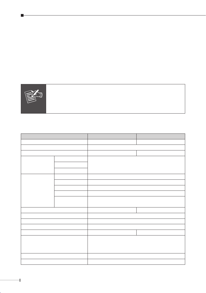
1.3 Technical Specications
Model KVM-810 KVM-1610
PC Port 8 16
Console 1
Max. PC Connections 64 256
PC Port
Connector (All
Female Type)
Console
Connection
Port Selection Keys 8 16
PC Selection On Screen Display Menu / Hot Key / Button
Video Resolution Up to 1920 X 1440 60HZ
Dimension (W x D x H) 440 x 185 x 42 mm
Console Connection 2.75 KG 3 KG
Environmental Specication
Power Requirement 12V DC, 1.5A
On Screen Display Control FCC, CE
Keyboard
3-in1 HDDB 15 pin FemaleMouse
Monitor
Keyboard Mini DIN 6 pin Female
Mouse Mini DIN 6 pin Female
Monitor HDDB 15 pin Female
Mouse USB USB (TYPE A)
Keyboard USB
(Female)
USB (TYPE A)
Operating temperature: 5 ~ 40 Degree C
Storage temperature: -20 ~ 60 Degree C
Relative humanity: 0 ~ 80% (non-condensing)
Page 7

7
Chapter 2 Installation
2.1 System Requirements
KVM-810
Description 8-Port Combo KVM Switch
One VGA Monitor
One PS/2 Keyboard
Console side
Computer side
[Optional]
KVM-1610
Description 16-Port Combo KVM Switch
Console side
Computer side
[Optional]
One PS/2 Mouse
One USB Keyboard
One USB Mouse
8 x 3-in-1 KVM Cable (VGA / Keyboard / Mouse)
One VGA Monitor
One PS/2 Keyboard
One PS/2 Mouse
One USB Keyboard
One USB Mouse
16 x 3-in-1 KVM Cable (VGA / Keyboard / Mouse)
2.2 Cable Diagrams
3-in-1 KVM Cable is for PS2 Computer or Server; connected USB PC or Server,
Please use PS2 to USB Adapter
Connected to CPU port of KVM
Connected to Console port of PC or Slave KVM
Page 8

8
PS/2 Cable:
Mini Din 6 pin Male to Male
AT to PS/2 keyboard adapter: (Optional)
Din 5 pin Male to Mini Din 6 pin Female
VGA Cable:
HDB15 pin Male to Male
PS2 to DB9 adapter: (Optional)
Mini Din 6 pin Female to DB 9 pin Female
2.3 Product Details
Front panel
8-port KVM Switch
16-port KVM Switch
Page 9

9
LEDs Color Description
Power Blue An blue light indicates that the KVM is operating
Port
OSD OSD Control Mode
Console-Reconrmed
Real panel
8-port KVM Switch
16-port KVM Switch
Green
Red The situation of being connected to the port.
Button Description
The PC or KVM connected to the corresponding port is on and
operating
The keyboard and mouse will be reconnected, and the
EDID in the screen will be read again.
Port Description
CPU Install the cable connected to a PC here
In the Master KVM, connect the monitor, keyboard and mouse here.
Console
In the Slave KVM, connect the cable come from the Master CPU port
here
2.4 Hardware Installation
Before installation, please make sure all of peripherals and computers have been
turned off.
Step 1: Rack Installation
Find a convenient place to put your KVM Switch. Its 19” rack mount form factor
makes it ideal stackable on 19” rack. When stacking to a rack, attach the included
brackets to the sides of the KVM Switch. Take note of the length of your cables
so that your computers, KVM Switch, keyboard, mouse and monitor are distanced
properly.
Page 10

10
Step 2 Connecting Monitor to the KVM Switch
The rear side of PC
Connect the monitor to the KVM Switch. Using the attached cable, or the one
included with your monitor, connect it to the HDDB-15 female port on the back of
the KVM unit labeled with the monitor symbol at the CONSOLE port connector.
Step 3: Connecting Keyboard to the KVM Switch
Connect the keyboard and mouse to the KVM Switch. If you have an AT type
keyboard, you will need an AT to PS/2 adapter.
Step 4: Connecting Mouse to the KVM Switch
Connect the mouse to the KVM Switch.
Step 5: Connecting VGA/Mouse/Keyboard port of PC(s) to the KVM Switch
Install the Master KVM to the 3-in-1 cable (same as the cable for connecting the
KVM to the PC) in the middle of the Slave KVMs.
Step 6: Check Again
Double-check all of the connections. You can check the color of keyboard and
mouse connector to make sure the keyboard and mouse cables go to the correct
ports.
Step 7: Connecting Other PCs
Repeat step 5 for the remainder of the computers.
Step 8: Connecting KVM Power
Attach the power supply to the KVM unit and plug the other end into an electrical
receptacle. Now you will see the LED for Port 1 light up, and you will hear a beep.
Switch on your monitor.
Page 11

11
Note
It is not necessary to power down the whole system for install a
new PC Or KVM thereafter. All you need is to make sure that the
new PC or KVM is OFF during the installation. If the KVM powers
down due to external Factors (such as power failure or the power
of the KVM is turned off), we recommend you to reinstall the whole
system.
2.5 Cascade Chain Connection Diagram
Step 1: Rack Installation
Find a convenient place to put your KVM Switch. Its 19” rack mount form factor
makes it ideal stackable on 19” rack. When stacking to a rack, attach the included
brackets to the sides of the KVM Switch. Take note of the length of your cables
so that your computers, KVM Switch, keyboard, mouse and monitor are distanced
properly.
Step 2: Connecting Monitor to the KVM Switch
Connect the monitor to the KVM Switch. Using the attached cable, or the one
included with your monitor, connect it to the HDDB-15 female port on the back of
the KVM unit labeled with the monitor symbol at the CONSOLE port connector.
Step 3: Connecting Keyboard to the KVM Switch
Connect the keyboard and mouse to the KVM Switch. If you have an AT type
keyboard, you will need an AT to PS/2 adapter.
Step 4: Connecting Mouse to the KVM Switch
Connect the mouse to the KVM Switch.
Step 5: Connecting console port of KVM to the KVM Switch
Use the 3-in-1 cable(or with PS2 to USB Adaptor) to connect the CPU port of the
master KVM in parallel to the console port of the slave KVM.
Page 12

12
Cascade Max. 8 KVM
KVM-810 rear panel
KVM-810 rear panel
Max. 64 PCs
Main Console
Step 6: Connecting VGA/Mouse/Keyboard port of PC(s) to the KVM Switch
The rear side of PC
Install the Master KVM to the 3-in-1 cable (same as the cable for connecting the
KVM to the PC) in the middle of the Slave KVMs.
Step 7: Check Again
Double-check all of the connections. You can check the color of keyboard and
mouse connector to make sure the keyboard and mouse cables go to the correct
ports.
Step 8: Connecting Other PCs
Repeat step 5 - 6 for the remainder of the computers.
Step 9: Connecting KVM Power
Attach the power supply to the KVM unit and plug the other end into an electrical
receptacle. Now you will see the LED for Port 1 light up, and you will hear a beep.
Switch on your monitor.
Page 13

13
Chapter 3 Operations
Note
3.1 Manual Key
It is the simplest switching method. You just need to press the Port Selection
Switch on the front panel of the KVM. The Selection LED (Red) is on, indicating
that you are switching to the corresponding port.
1. The Port Selection Switch functions only when connected to a
PC.
2. If the Offline Skip of the OSD System Setting is Auto, then you
can not make any switch when pressing an offline Port Selection
switch.
3. For Auto Scan Mode, none of the Port Selection Switches functions
3.2 Hot Key and Mouse Clicking
Hot key and mouse clicking are applicable for switching a small section. You can
select the SVS (Smart View Setting) from the OSD of the PC rst (for a quick
switch of PC) and use the keyboard (press the Ctrl key twice) or the mouse (press
and hold the middle button while pressing the left or right button) to switch to the
previous or next set of PC.
The mouse must have at least 3 keys. As far as you select a PC with the SVS, you
can use this method for the switch.
3.3 OSD (On Screen Display)
Press the NumLock on the keyboard twice or simultaneously press the Push
Buttons 1 and 2 of the Port Selection Switch on the KVM panel to start the OSD.
Use the key Up, Down and Enter keys on the keyboard to switch or directly move
the mouse to the target PC, and then double click the left button.
Additionally, you also can use the numeric keys to enter the direct switch. For
example, if you want to switch a PC to the Slave KVM port 04 under the Master
KVM port 03, then you can start the OSD and then directly enter 0304. If you are
using a standalone machine, then just enter the rst two digits.
More OSD related information is given in the following OSD sections.
Start
Press the NumLock twice or the Port Selection Switches 1 and 2 on the panel to
enter the OSD.
Page 14

14
Note
If you have modified the Hot Key for starting the OSD and are
Note
unable to enter the OSD by pressing NumLock, and then you can
start the OSD by using Port Selection Switch first, and then press
F9 to enter into the System Setting to modify the options of the
OSD Entry Hot Key.
If you have modied the Hot Key for starting the OSD and are unable to enter the
OSD by pressing NumLock, then you can start the OSD by using the Port Selection
Switch rst, and then press F9 to enter into the System Setting to modify the
options of the OSD Entry Hot Key.
Operation
You can operate the options by keyboard or mouse. For the keyboard operation,
besides the common Up and Down keys, there are special function keys such as
Enter, Space Bar, Function Key (F1, F4…) under the OSD remark eld. For the
mouse operation, the left key refers to Enter and the right key refers to Exit. For
example, move the mouse point to your desired PC, and click the left key. The
selection bar will move to that position and then click the left key again for the
execution.
You must use the keyboard to complete the two functions: Name
Edit and Password.
Switch Menu
Master List
1 03-04:Mail Ser 4
2
3
4
LIST: MASTER
PWR C# KVM NAME SVS
● 01 Admin
● 02
● 03 04 Mail Group
04
● 05 Peter
● 06 08 Web Group
● 07 16 Data Group
08
: Move Space: Edit Esc: Exit
F1: Smart View Enter: Switching
F4: Auto Scan F9: System Setting
F5: Clear Name List
Press
Enter
Page 15

15
Slave List
Note
03-04:Mail Ser 4
LIST: Mail Group
PWR C# KVM NAME SVS
● 01 Mail Ser 1
● 02 Mail Ser 2
● 03 Mail Ser 3
● 04 Mail Ser 4
: Move Space: Edit Esc: Exit
F1: Smart View Enter: Switching
F4: Auto Scan F9: System Setting
F5: Clear Name List
1. This eld provides the information of the currently connected PC. As shown in
the gure above, 03 refer to the Port Number of the Master; 04 refer the Port
Number of the Slave; and Mail Ser 4 is the name of this PC dened by Users. If
a PC connects to the Master, then the number consists of the rst two digits. If
a User has not given a name for the PC, the name eld will be blank.
2. This eld shows the list of the Master KVM or a certain set of Slave KVM
currently displayed on the OSD. We recommend you to give a name to the Slave
KVM, or else the display after LIST: will be blank.
3. This eld shows the list of connections to the KVM, and the elds are described
below: PWR: It shows the status of power supply and indicates a normal power
supply for the equipment (PC or KVM) connected to the CPU port.
C#: It shows the channel number; the CM-1204 will display 01~04; the CM-1208
will display 01~08 and the CM-1216 will display 01~08; 09~16 (Since the
screen cannot display all at a time, therefore you can use PgUp/PgDn to
switch the pages).
KVM: It shows the KVM model. If there is a number in this eld, it shows that a
set of KVM connects to this port. The number 04 indicates Port 4 and 08
indicates Port 8 and 16 indicates Port 16 and so on.
If the connected KVM is not on, there will have no number in this
field.
NAME: It shows the name of the equipment, and users can name the Slave KVM
or PC on their own. There are a total of 12 characters selected from the group of
“A~Z”, “a~z”, “0~9” , “+” , “–” , “*” , “/” , “=” , “[” , “]” , “,” , “·” , “:”.
Page 16

16
Note
Please use the CapsLock to toggle the upper and lower cases.
SVS: It shows the Smart View Setting; use to open and to close. The SVS
is blank and not clickable if the KVM is connected in parallel. If this option is
set to open, then you can make the switch by operating the Hot Key Switch
or Mouse Clicking or selecting the option by Auto Scan. You also can use
mouse to click this eld.
Selection BAR: It shows the selection bar (Green); you can use the keys on
the board to move the selection bar, and the situated position
indicates the selected target for giving instructions. For example,
if the selection bar points at C#05 and you press Enter, then the
system will switch to that particular PC or press the “Space BAR”
to start editing the name. Press F4 to enable/disable the SVS
option.
4. Instruction Hint Field:
:
(Move)
SPACE:
(Edit)
ESC:
(Exit)
F4:
(Auto Scan)
F9:
(System Setting)
F5:
(Clear Name
List)
F1:
(Smart View)
Use the keys on the keyboard or the mouse to move
the selection bar
The “Space BAR” on the keyboard is used to start editing
the name of the PC or KVM.
Use the “Esc” key on the keyboard to exit the current
option or exit OSD.
Use the F4 key to run Auto Scan, and you can set the
residing time, channel display time and mode of the Auto
Scan from System Setting.
Use the F9 key to enter into the System Setting Menu.
Use the F5 key to clear the values of all Name elds. If
you clear the name list under the Master screen, then you
will also clear the name lists under all slaves. If you clear
the name list under a certain slave, then you only clear
the name list under that particular Slave KVM.
It switches the Smart View Setting.
Page 17

17
System Setting Menu
System Setting
Channel Display Mode Full
Channel Display Tim 5 Sec
Auto Scan Time 5 Sec
OSD Entry Hot Key Number Lock
Hot Key Switching OFF
Mouse Clicking OFF
Beeper Sound ON
Ofine Skip Manual
OSD Language English
Security Level None
Console Lock Time 5 Min
Space Change
Esc Exit
F1 Information
F4 OSD Position
F8 Restore Default Setting
Item Description Default Other Selection
For Port Switching, Auto Scan
Channel
Display Mode
Channel
Display Time
Auto Scan
Time
OSD Entry
Hot Key
Hot Key
Switching
and OSD Close, the Monitor will
show the Channel information
and mode selection.
It shows the time for displaying
channel information.
For Auto Scan, it shows the
residing time for each port.
Select to turn on the hot keys
of the OSD control screen.
Turn on/off the “Ctrl” hot keys
on the keyboard for switching
computer functions.
Move
Full Number, Name
5 Sec
5 Sec
NumLock
OFF ON
10Sec, Always,
None
10Sec, 20Sec,
30Sec, 60Sec
Scroll Lock, Shift,
None
Page 18

18
Mouse
Clicking
Beeper
Sound
Ofine Skip
OSD
Language
Security
Level
Console Lock
Time *1
*1: You can select this option only if the Security Level is not “None”.
F1: Information; It provides the model name and F/W version information, which
is helpful for users to understand the updated version.
F4: OSD Position; you can enter the OSD position to make adjustments; we
recommend you to unify the resolution for all computer display mode, and use
this function again to adjust the OSD position. You can use the Up, Down, Left
or Right keys on the keyboard or a mouse to move the OSD position.
F8: Restore Default Setting; Restore the factory default settings. Please note that
all name lists will be cleared and the system settings are set to the default
settings as shown in the table above.
Esc: Exit; Exit the system setting and close the OSD. If you have made changes in
this option, the system will ask whether or not you want to save the setting
before the selected option is effective.
Auto Scan Mode: You can start the OSD rst and press “F4” to enter the Auto
Turn on/off the keys of the
mouse for switching computer
functions.
Turn on/off the beeper sound
function.
Set the ofine skip function to
auto or manual.
Select the language for the
OSD.
Select the security mode and
level.
The lock time of console port. 5 Min
Scan Mode. If you want to scan the PC, you must use the
Smart View Setting to select the Auto Scan Time in the System
Setting for the residing time, which includes 5 sec, 10 sec, 20
sec, 30 sec and 60 sec. You can adjust the Channel Display
Mode and Channel Display Time from the Channel Display
mode. By then, all keys on the panel, keyboard and mouse are
not operable. You can only use the ESC key to exit the Auto
Scan Mode.
OFF ON
ON OFF
Manual Auto
English
None Low, High
Francis, Deutsch,
Italian, Espino
1Min, 3Min,
10Min, 30Min,
60Min
Page 19

19
Security Mode: Switch the Security Level from “None” to “Low” in the System
Setting, and enter your Password (“A~Z”, “0~9”, a maximum of
12 characters), and the security will be effective after you conrm
the Password. The use of the Console Lock Time is to set the
time to enter a security mode after the keyboard and mouse has
idled for a predetermined time. Once you enter into the security
mode, you need to enter the correct password before you can
move the mouse or enter any key from the keyboard. You need
a correct password to operate the whole system normally.
Important Note: What should I do if I forgot my Password?
After you enter a wrong password for 5 consecutive times, a time delay bar will
appear, and a set of “Magic Numbers” will show up at the bottom.
Record the magic numbers and contact with your distributor.
Console - Reconrmed: Simultaneously press the largest two numbered Port
Selection Switches on the panel to start the Console-
Reconrmed. If you change the Console equipment,
please use this function to let KVM reconrm the
equipment at the Console end once.
EDID & DDC: A vast majority of computer monitors supports the Extended Display
Identication Data (EDID) and allows data access by Display Data
Channel (DDC). The KVM also supports these two specications, but
the KVM only reads the EDID of the Monitor when the KVM is on. If
it is necessary to change monitors during an operation, please use
the Console Reconrmed function to read the EDID again.
Page 20

Chapter 4 Troubleshooting
Note
Conrm whether or not the cable is good and connected properly
Q1: What should we do if the keyboard has no response?
A: (1) Reinstall the keyboard by unplugging the keyboard from the control end
and then plugging it back.
(2) Reboot the PC.
(3) For Auto Scan Mode, press [Esc] to exit.
(4) Try another keyboard.
Q2: What should we do if the mouse has no respond?
A: (1) Reinstall the mouse by unplugging the mouse from the control end and
then plugging it back.
(2) Reboot the PC.
(3) For Auto Scan Mode, press [Esc] to exit.
(4) Try another mouse.
If you are using a special mouse, we recommend you to install the
mouse driver provided by the original manufacturer to maximize its
functionality.
Q3: What should we do if the OSD cannot display normally?
A: (1) If the setting for resolution exceeds 1920 x 1440, 60Hz, then set the
resolution within the specied range.
(2) If the KVM switch is a standalone, then power off the PC. Unplug the
special cable of the KVM switch and then power on the KVM switch.
Connect the special cable of the KVM switch and power on the PC.
(3) If the KVM switch is connected in series, then power off the PC. Unplug
the special cable of the KVM switch. Power on the master KVM switch and
then start the slave KVM switch. Connect the special cable to the KVM
switch and power on the PC.
Q4: What should we do if there is a video problem?
A: (1) Check whether or not the setting of resolution is too high. The Smart
View supports VGA, SVGA, Multisync and XGA (interlaced) resolutions up
to 1920 x 1440, 60Hz.
(2) The quality of cable is not good enough. Please use high-quality Smart
View cables.
20
 Loading...