

Page 1

User’s Manual
IKVM-17080 / IKVM-17160
Drawer 8/16 Port Combo-Free IP
KVM Console with 17" LCD
Display
Page 2

Copyright
Copyright (C) 2012 PLANET Technology Corp. All rights reserved.
The products and programs described in this User’s Manual are licensed products of PLANET
Technology, This User’s Manual contains proprietary information protected by copyright, and this
User’s Manual and all accompanying hardware, software, and documentation are copyrighted.
No part of this User’s Manual may be copied, photocopied, reproduced, translated, or reduced to
any electronic medium or machine-readable form by any means by electronic or mechanical.
Including photocopying, recording, or information storage and retrieval systems, for any purpose
other than the purchaser's personal use, and without the prior express written permission of
PLANET Technology.
Disclaimer
PLANET Technology does not warrant that the hardware will work properly in all environments
and applications, and makes no warranty and representation, either implied or expressed, with
respect to the quality, performance, merchantability, or fitness for a particular purpose.
PLANET has made every effort to ensure that this User’s Manual is accurate; PLANET disclaims
liability for any inaccuracies or omissions that may have occurred.
Information in this User’s Manual is subject to change without notice and does not represent a
commitment on the part of PLANET. PLANET assumes no responsibility for any inaccuracies
that may be contained in this User’s Manual. PLANET makes no commitment to update or keep
current the information in this User’s Manual, and reserves the right to make improvements to
this User’s Manual and/or to the products described in this User’s Manual, at any time without
notice.
If you find information in this manual that is incorrect, misleading, or incomplete, we would
appreciate your comments and suggestions.
FCC
This device has been tested and found to comply with Part 15 of the FCC Rules. Operation is
subject to the following two conditions:
(1) This device may not cause harmful interference
(2) This device must accept any interference received. Including interference that may cause
undesired operation.
CE
This equipment is in compliance with the requirements of the following regulations: EN 55 022:
CLASS A
WEEE regulation
To avoid the potential effects on the environment and human health as a result of the
presence of hazardous substances in electrical and electronic equipment, end users
of electrical and electronic equipment should understand the meaning of the
crossed-out wheeled bin symbol. Do not dispose of WEEE as unsorted municipal
waste and have to collect such WE
EE separately.
Trademarks
The PLANET logo is a trademark of PLANET Technology. This documentation may refer to
numerous hardware and software products by their trade names. In most, if not all cases, these
designations are claimed as trademarks or registered trademarks by their respective companies.
Revision
User’s Manual for Drawer 8/16 Port Combo-Free IP KVM Console with 17" LCD Display
Model: IKVM-17080/17160
Rev: 1.0 (March, 2012)
Part No. EM-iKVM-17080/17160_v1.0
Page 3

0BSafety Instructions
1. Please disconnect this equipment from AC outlet before cleaning. Don’t use liquid or
sprayed detergent for cleaning. Use moisture sheet or clothe for cleaning.
2. For pluggable equipment, the socked-outlet shall be installed near the equipment and
shall be easily accessible.
3. Please keep this equipment from humidity.
4. Lay this equipment on a reliable surface when install. A drop or fall could cause injury.
5. Do not leave this equipment in an environment unconditioned, storage temperature
above 60
o
C, it may damage the equipment.
6. The opening on the enclosure is for air convection hence the equipment from overheating.
DO NOT COVER THE OPENING.
7. Make sure the voltage of the power source connect the equipment to the power outlet.
8. Please keep the power cord such a way that people can not step on it. Do not place
anything over power cord. The power cord must rate for the voltage and current marked
on the product’s electrical ratings label. The voltage and current rating of the cord should
be greater than the voltage and the current rating marked on the product.
9. All cautions and warning on the equipment should be noted.
10. If the equipment is not in use for long time, disconnect the equipment from mains to avoid
being damaged by transient over-voltage.
11. Never pour any liquid into ventilation openings; this could cause fire or electrical shock.
12. Never open the equipment. For safety reason, qualified service personnel should only
open the equipment.
13. If one of the following situations arises, get the equipment checked by service personnel.
The Power Cord or plug is damaged.
Liquid has penetrated into the equipment.
The equipment has been exposed to moisture.
The equipment has not worked well or you can not get it work according to
User’s Manual.
The equipment has dropped and damaged.
If the equipment has obvious signs or breakage
I
Page 4

1BIndex of Contents
USafety InstructionsU ......................................................................................................................................I
UIndex of ContentsU ........................................................................................................................................I
U1.U UGeneral InformationU .......................................................................................................................... 1
U1.1 Packing ListU ............................................................................................................................... 1
U1.2 Product FeatureU ........................................................................................................................ 1
U1.3 Product SpecificationU................................................................................................................ 2
U2. InstallationU ......................................................................................................................................... 4
U2.1 Before InstallationU........................................................................................................................4
U2.2 Hardware Kits ContentsU.............................................................................................................. 5
U2.3 LCD ComponentsU.........................................................................................................................7
U2.4 Connecting the ConsoleU ............................................................................................................... 8
U2.5 Web ManagementU ........................................................................................................................ 9
U3. OSD OperationU ............................................................................................................................... 10
U3.1 Panel Controls and LCD OSD FunctionU .................................................................................. 10
U3.2 KVM OSD FunctionU .................................................................................................................. 12
U3.2.1 Manual KeyU .....................................................................................................................12
U3.2.2 Hot Key and Mouse ClickingU .........................................................................................12
U3.2.3 OSD (On Screen Display)U ...............................................................................................12
U4. Remote UsageU ...................................................................................................................................19
U4.1 PrerequisiteU................................................................................................................................. 19
U4.2 Login and LogoutU....................................................................................................................... 20
U4.2.1 LoginU ................................................................................................................................20
U4.2.2 LogoutU ..............................................................................................................................22
U4.3 The Remote ConsoleU ..................................................................................................................22
U4.3.1 Remote Console Control BarU .........................................................................................22
U4.3.2 Remote Console Status LineU...........................................................................................27
U5. Menu OptionsU .................................................................................................................................... 28
U5.1 Remote ControlU .......................................................................................................................... 28
U5.1.1 KVM ConsoleU ..................................................................................................................28
U5.1.2 Telnet/SSHConsoleU..........................................................................................................28
U5.1.3 Remote WakeupU .............................................................................................................. 29
U5.2U UVirtual MediaU ............................................................................................................................. 32
U5.2.1 Drive RedirectionU ............................................................................................................32
U5.2.2 Virtual DriveU....................................................................................................................33
U5.2.3 CD/DVD ImageU ...............................................................................................................34
I
Page 5

U5.3 User ManagementU ...................................................................................................................... 36
U5.3.1 Change PasswordU ............................................................................................................36
U5.3.2 UsersU .................................................................................................................................36
U5.4 KVM SettingsU ............................................................................................................................. 37
U5.4.1 User ConsoleU ....................................................................................................................37
U5.4.2 Keyboard/MouseU .............................................................................................................40
U5.4.3 VideoU ................................................................................................................................41
U5.5 Device SettingsU............................................................................................................................ 42
U5.5.1 NetworkU............................................................................................................................42
U5.5.2 Dynamic DNSU ..................................................................................................................44
U5.5.3 SecurityU ............................................................................................................................46
U5.5.4 CertificateU ........................................................................................................................48
U5.5.5 Serial PortU ........................................................................................................................49
U5.5.6 Date / TimeU.......................................................................................................................49
U5.5.7 Event LogU.........................................................................................................................50
U5.5.8 AuthenticationU .................................................................................................................51
U5.5.9 USBU...................................................................................................................................52
U5.5.10 Config FileU......................................................................................................................52
U5.6 MaintenanceU ...............................................................................................................................52
U5.6.1 Device InformationU .........................................................................................................52
U5.6.2 Even logU............................................................................................................................53
U5.6.3 Unit ResetU.........................................................................................................................54
UAppendix A Cable Connectors SpecificationsU ....................................................................................... 55
UAppendix B Troubleshooting & Frequently Asked QuestionsU............................................................. 56
II
Page 6

1. 2BGeneral Information
The PLANET IKVM-17080 / IKVM-17160 is the drawer KVM with single-rail console
design offering industrial level input solution, which optimizes your space utilization by
controlling your systems in just 1U space on the rack. The separate rail design helps
users to use the 8/16-Port combo-free KVM easily. Users do not have to prop the heavy
console during the installation but just lock the rails into the rack and then pull the KVM
console into the rails.
The IKVM-17080 / IKVM-17160 captures, digitizes and compresses video signal, then
transmits it with keyboard and mouse signals through IP network. Multiple remote sites
can monitor the same PC server simultaneously. With HTTPS/SSL authentication and
data encryption, the IKVM-17080 / IKVM-17160 provides a non-intrusive solution for
remote access and control. The remote access and control software operates on its
embedded processors only, but not on mission critical servers, so that there would be
no interference with server operation or decrease on the network performance.
The combo-free KVM Switch modules are loaded with rich features, such as one local
console port, Daisy chain capability, On Screen Display (OSD) menu, Password
security, Searching PC server name, Hot key control, Push button and Auto-Scan
control, complete keyboard and mouse emulation for simultaneously PC boot-up
processes.
5B1.1 Packing List
The complete package consists of:
One 1.8 m KVM cable. (HDB-15 / VGA + PS/2 x 2)
One 1.8m power cord
One user’s manual CD
One quick installation guide
Two Rack mount bracket kit
One Rack Mount Screw pack
Check to make sure that the unit was not damaged in shipping. If you encounter a problem,
contact your dealer.
Please read this manual thoroughly, and follow the installation and operation procedures
carefully to prevent any damage to the product, and / or any of the devices that connect to it.
1
Page 7

6B1.2 Product Feature
z Remote mass storage control
z 19” rack mount 1U size design, easy to install
z Cascade controls up to 64 computers from single consol
z No Software Required easy PC selection via On Screen Display (OSD) menu, Push
Buttons, Hot Keys
z Supports Combo KVM module to connect servers / KVM via USB & PS/2 connection
z Fully supports Logitech / Microsoft / IBM PS/2 mouse / trackball and compatible PS/2
mouse / trackball
z High Video Quality :resolution up to 1920 x 1440 (local side) or 1600 x 1200 (remote
side)
z Supports SSL protocol for any encrypted network traffic between itself and a connected
client
z Heavy-Duty Electroplate Steel
z Supports hot plug; not necessary to turn off the original system regardless of a newly
installed PC or KVM
z Supports password protection and PC server name search
1
Page 8
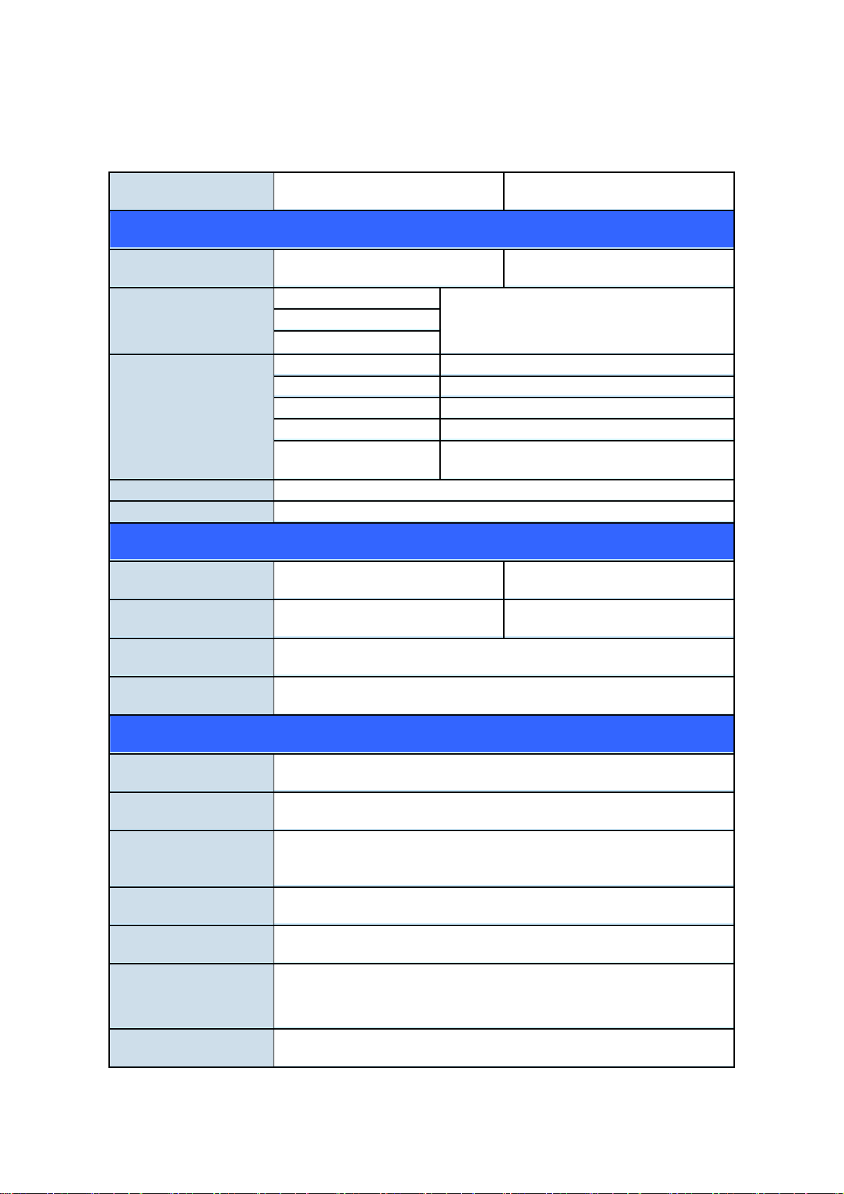
7B1.3 Product Specification
Model IKVM-17080 IKVM-17160
Hardware Interface
PC Port 8 16
PC Port Connector
(All Female Type)
Keyboard
Mouse
3-in1 HDDB 15 pin Female
Monitor
Console Connection
Keyboard Mini DIN 6 pin Female
Mouse Mini DIN 6 pin Female
Monitor HDDB 15 pin Female
Mouse USB USB (TYPE A)
Keyboard USB
USB (TYPE A)
(Female)
Keyboard Mouse 105 key keyboard with touch pad
Touch pad 1000 points/ inch (40 points/mm)-graphics tablet mode
Control Feature
Max. PC Connections 64 (by cascade 8 KVM-810) 256(by cascade 16 KVM-1610)
Port Selection Keys 8 16
PC Selection On Screen Display Menu / Hot Key / Button
KVM Video Resolution Up to 1920X1440 60Hz
Hardware Specification & Environment
Display Size 17 inches
Panel Type 4CCFL LCD Panel
LCD Resolution
Capabilities
Maximum Resolution up to 1280 x 1024 (SXGA)
Pixel Pitch Supports 0.264(H) x 0.264(V) / 0.294(H) x 0.294(V)
Backlight lifetime 50,000 hrs
Operating System Windows 98SE/ ME/ 2000/ XP/ 2003/ Vista/ 7 Server, Linux,
Mac OS9/ OSX and Sun Microsystems
Chassis Construction Heavy duty steel materials
2
Page 9

Rail slide Dimension 45 cm (extended length 22cm)
Dimension (W x D x H) 440 x 450 x 44 mm
Weight 10.5 Kg
Environmental
Specification
Operate: 5 ~ 40 Degree C (41 ~ 104 Degree F)
Storage: -20 ~ 60 Degree C ( -4 ~ 140 Degree F)
Relative humanity: 0 ~ 80% (non-condensing)
Power Requirement Universal 100~240V AC input
Certification FCC, CE
3
Page 10

2. Installation
8B2.1 Before Installation
1. Please check all peripherals according the list before installation. To make sure of
the whole unit was not damaged and lost during shipping process. If you
encountered any problem, please contact your dealer.
2. Before installation, make sure all peripherals and computer have been turned off.
3. The standard brackets are for 500 ~ 800 mm (distance means front bracket to rear
bracket) cabinet, contact your dealer if you need longer rear brackets.
4. If your cabinet depth is above 800 to 1000 mm, please contact your dealer for the
stretch rails and replace it for your demand.
5. Reliable accessories of rack-mounted equipment should be maintained. Particular
attention should be given to supply connections other than direct connections to the
branch circuit.
6. The KVM and console are a little bit heavy, please prevent these devices from falling
down during the installation. That may make some people hurt and the console
damage.
9B
4
Page 11
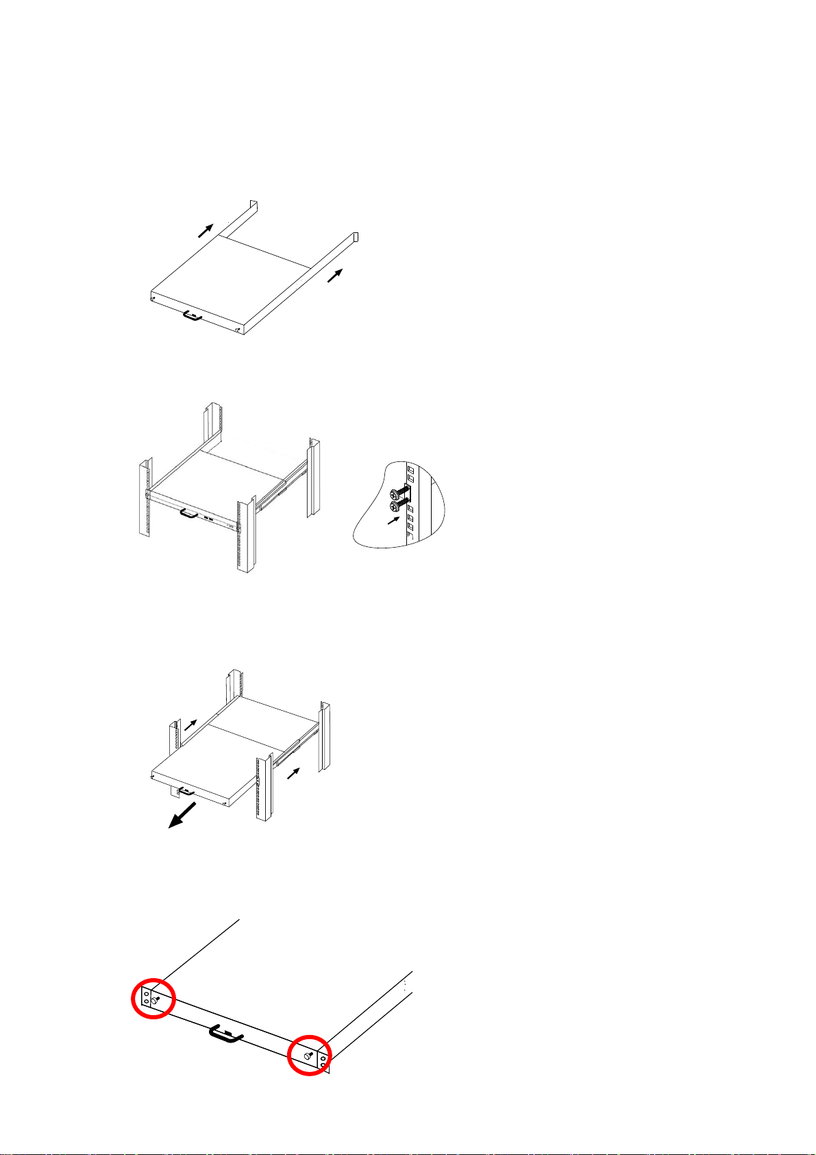
2.2 Hardware Kits Contents
1. Adjust rail with pull or push to fit your cabinet
2. Install front and rear bracket on cabinet.
3. Repeat step 1~2 for the other side.
4. Pull the console until rails automatically are locked. When users hardly push the
console and it can be unlocked by the power is over 4kg.
5. Pull and turn the lock knobs (left and right at the same time) then users can
open console to operate.
5
Page 12
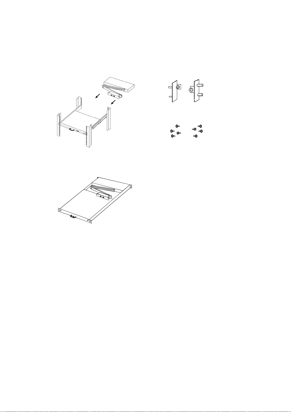
6. Put the KVM module into the console form the back. There are two ways to install the
KVM module in suitable position, users can fix KVM module with the KVM
accessories (Both sides) or the extra Rack- mounted Screws (Bothsides).
KVM accessories (L& R) X2
7. Finish installation as below.
Extra rack- mounted Screws X8
6
Page 13
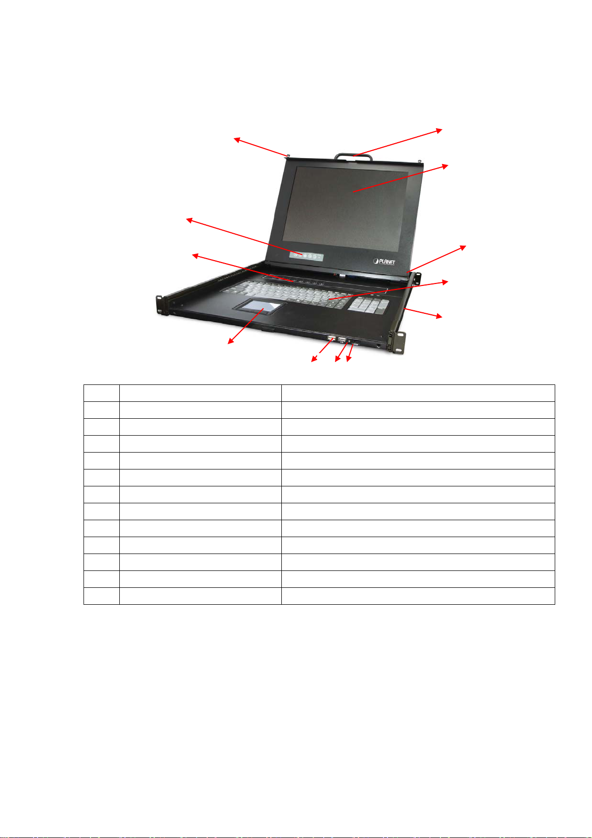
10B2.3 LCD Components
3
11
1
2
4
9
6 7
8
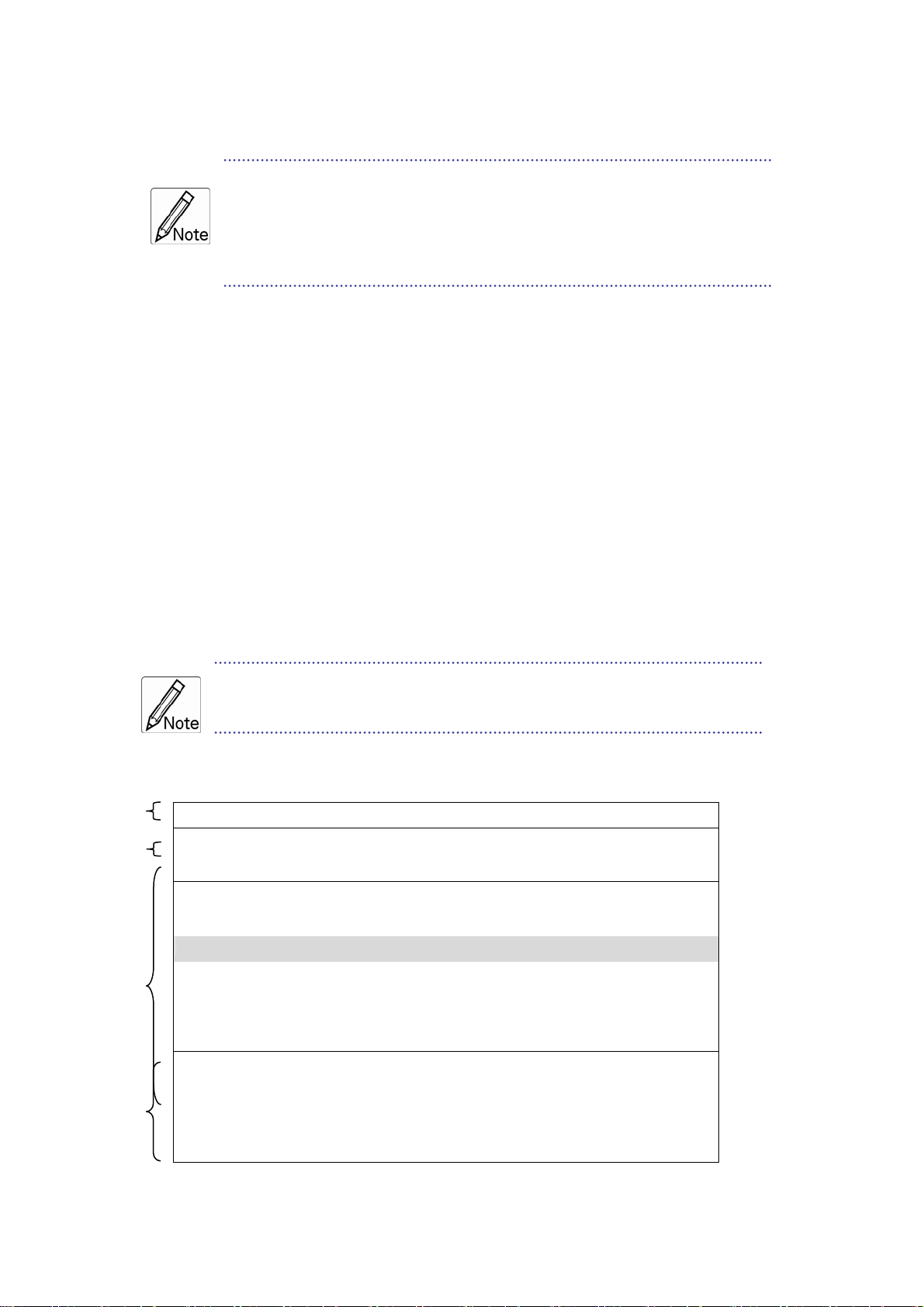
No. Component Function Description
Handle Holder Pull to Slide the LCD console in or out
1
LCD Display Panel Display
2
LCD Panel OSD Buttons Controls Display Required Quality
3
LED Indicators Switching Operation for KVM Module ( Optional )
4
Slide Rail Single Slide Rail
5
USB Ports x 2 (K/B, Mouse) Plug-in external K/B and Mouse.
6
Power LED Indicates Power Status
7
Power Switch Turn on / Turn off
8
Touch Pad Mouse Operation
9
Keyboard Module Keyboard Operation
10
LCD Lock Screws Fix or Release LCD panel
11
8/ 16 ports KVM Modular KVM for 8/ 16 ports
12
12
10
5
7
Page 14
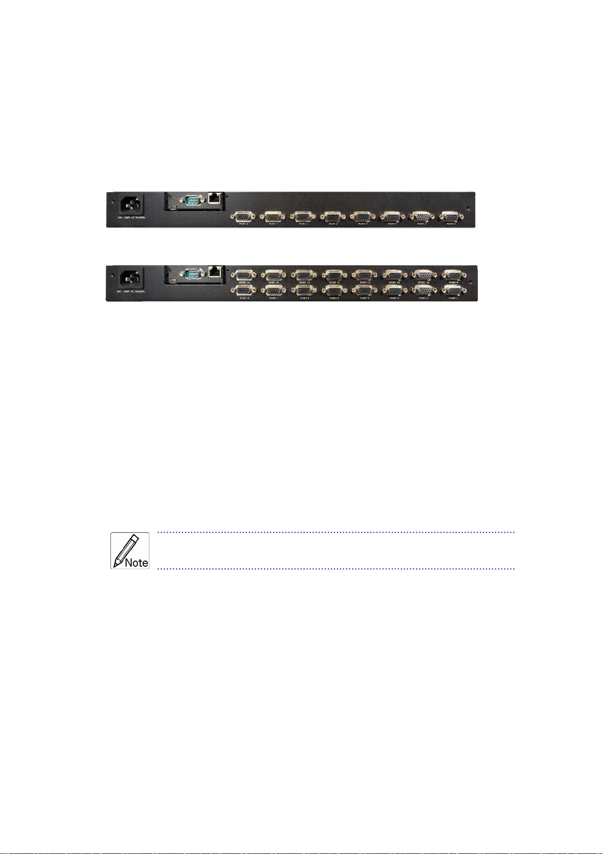
11B2.4 Connecting the Console
To connect an LCD console to a computer, perform the following steps
8 Port of KVM
16 Port of KVM
1. Turn off your computer. You should always turn off your computer before connecting or
disconnecting a device.
2. Connect the video (VGA) connector of the KVM cable to the video card connector on the
rear panel of your computer.
3. Identify and connect the PS/2 mouse and PS/2 keyboard connector to the correct PS/2
ports on the rear panel of your computer. Or you can use USB interface to connect your
computer (Use PS/2-USB switch to select your interface). The switch has to be on PS/2
side when you use PS/2 interface connector.)
Please don't plug PS/2 and USB cables at the same time
8
Page 15
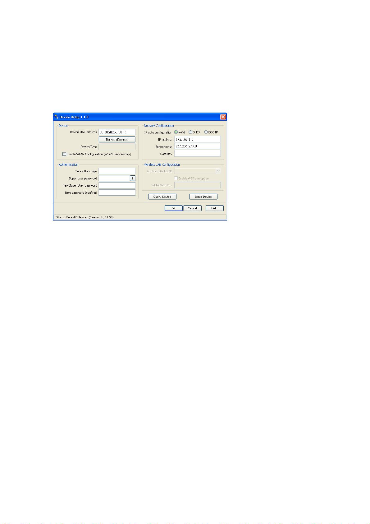
12B2.5 Web Management
If you have installed the IP-KVM on a network that enables DHCP, you can use the
PSetup to find out the IP-KVM’s IP.
1. Run "psetup_1.1.0.exe" from the CD
2. Please click on Refresh button to find your IKVM-17080/17160 in the network. You
can find the MAC address labeled on the bottom side of the IP-KVM module. MAC
address is detected as connection from computer and IP-KVM is valid through USB or
network.
3. [DHCP server available in the Network] Lanuch Web Browser and key in the IP
address of the IKVM-17080/17160. Please configure your PC to the same IP subnet as
well.
4. [DHCP server not available in the Network] Lanuch Web Browser and key in the
default IP address of the IKVM-17080/17160. If there is no DHCP server in the
network, your IKVM-17080/17160 will use IP address 192.168.0.20 as its default. Please
configure your PC to the same IP subnet as well.
5. As soon as the Web browser start up, IKVM-17080/17160 will prompt for User name
and Password. Please key in "super" and "pass".
6. You may now start to configure your IKVM-17080/17160 such as Remote Control,
Network Configuration, and so on.
9
Page 16
3. OSD Operation
A
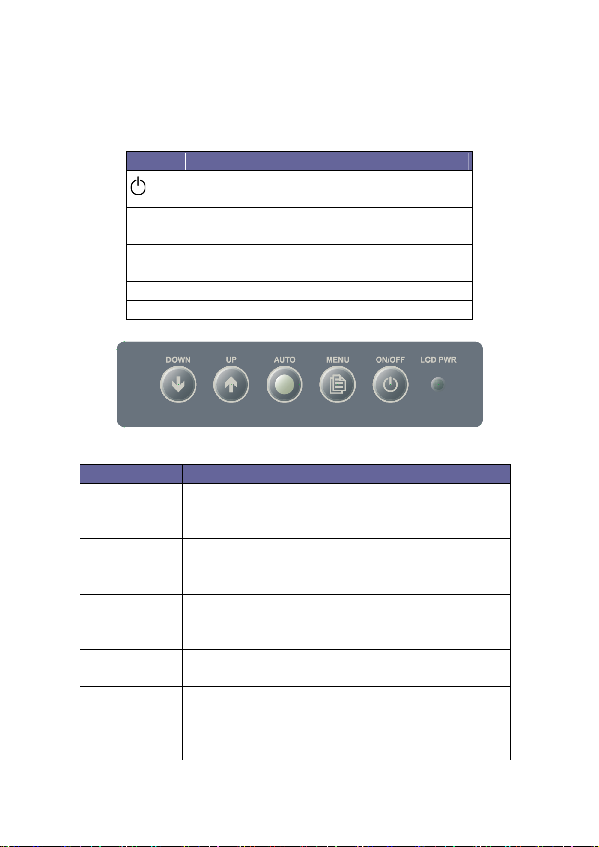
13B3.1 Panel Controls and LCD OSD Function
Controls Description
Soft power on/off button. Adjacent LED is lit when
on.
To access the main menu. This button also acts as
Menu
the “Enter” button.
Auto-synchronize and scale down display to any
Auto
valid factory preset timings.
▲UP Press to scroll the function you want to adjust.
▼DOWN Press to scroll the function you want to adjust.
Table 3.1 Panel Controls
Figure 3-1. OSD Control Bar
Controls Description
Automatically size, cent d fine tunes Video ers direction an
AUTO
signal to eliminate “noise” and direction
BRIGHTNESS reen image Adjusts back ground black level of the sc
CONTRAST Adjusts for ground white level of the screen image
SHARPNESS Adjusts the clarity and focus of the screen image
H.POSITION Moves the screen image left or right
V.POSITION Moves the screen up or down
djusts image distortion appearing as vertical bars or “noise”
CLOCK
on the screen
distortion appearing as horizontal “noise” on Adjusts image
PHASE
the screen
COLOR
Adjusts color temperatures for users
METER
Allows you to choose from among five languages as
LANGUAGE
English, French , German , Italia , Simplified Chinese,
10
Page 17
Espanola, and Nederland
SPEAKER Volume control
OSD
V.P N
OSITIO
OSD
H.P N
OSITIO
Adjust operation
Adjust operation of right/left on the screen
of up/down on the screen
O OSD “time of staying” on the screen SD OFF TIME
RECALL Returns all controls back to factory sorting
SOURCE Analog/Digital signal choice
EXIT/SAVE Exit OSD control
11
Page 18

14B3.2 KVM OSD Function
24B3.2.1 Manual Key
It is the simplest switching method. You just need to press the Port Selection Switch on
the front panel of the KVM. The Selection LED (Red) is on, indicating that you are
switching to the corresponding port.
1. The Port Selection Switch functions only when connected to a PC.
2. If the Offline Skip of the OSD System Setting is Auto, then you can not
make any switch when pressing an offline Port Selection switch.
3. For Auto Scan Mode, none of the Port Selection Switches functions
25B3.2.2 Hot Key and Mouse Clicking
Hot key and mouse clicking are applicable for switching a small section. You can select
the SVS (Smart View Setting) from the OSD of the PC first (for a quick switch of PC) and
use the keyboard (press the Ctrl key twice) or the mouse (press and hold the middle
button while pressing the left or right button) to switch to the previous or next set of PC.
The mouse must have at least 3 keys. As far as you select a PC with the SVS,
you can use this method for the switch
.
26B3.2.3 OSD (On Screen Display)
Press the NumLock on the keyboard twice or simultaneously press the Push Buttons 1
and 2 of the Port Selection Switch on the KVM panel to start the OSD. Use the key Up,
Down and Enter keys on the keyboard to switch or directly move the mouse to the target
PC, and then double click the left button.
Additionally, you also can use the numeric keys to enter the direct switch. For example,
if you want to switch a PC to the Slave KVM port 04 under the Master KVM port 03, then
you can start the OSD and then directly enter 0304. If you are using a standalone
machine, then just enter the first two digits.
More OSD related information is given in the following OSD sections.
Start
Press the NumLock twice or the Port Selection Switches 1 and 2 on the panel to enter the
OSD.
12
Page 19
If you have modified the Hot Key for starting the OSD and are unable to
enter the OSD by pressing NumLock, then you can start the OSD by
using Port Selection Switch first, and then press F9 to enter into
the System Setting to modify the options of the OSD Entry Hot Key.
If you have modified the Hot Key for starting the OSD and are unable to enter the OSD
by pressing NumLock, then you can start the OSD by using the Port Selection Switch first,
and then press F9 to enter into the System Setting to modify the options of the OSD Entry
Hot Key.
Operation
You can operate the options by keyboard or mouse. For the keyboard operation,
besides the common Up and Down keys, there are special function keys such as Enter,
Space Bar, Function Key (F1, F4…) under the OSD remark field. For the mouse
operation, the left key refers to Enter and the right key refers to Exit. For example, move
the mouse point to your desired PC, and click the left key. The selection bar will move to
that position and then click the left key again for the execution.
You must use the keyboard to complete the two functions: Name Edit and
Password.
Switch Menu
Master List
1
2
3
03-04:Mail Ser 4
LIST: MASTER
PWR C# KVM NAME SVS
● 01 Admin ♁
● 02 Θ
● 03 04 Mail Group Ο
04 Θ
● 05 Peter ♁
● 06 08 Web Group Ο
● 07 16 Data Group Ο
08 Θ
) *↑↓: Move Space: Edit Esc: Exit
F1: Smart View Enter: Switching
4
F4: Auto Scan F9: System Setting
F5: Clear Name List
Press Enter
13
Page 20

Slave List
03-04:Mail Ser 4
LIST: Mail Group
PWR C# KVM NAME SVS
● 01 Mail Ser 1 Θ
● 02 Mail Ser 2 Θ
● 03 Mail Ser 3 ♁
● 04 Mail Ser 4 ♁
) *↑↓: Move Space: Edit Esc: Exit
F1: Smart View Enter: Switching
F4: Auto Scan F9: System Setting
F5: Clear Name List
1 、This field provides the information of the currently connected PC. As shown in the
figure above, 03 refer to the Port Number of the Master; 04 refer the Port Number of the
Slave; and Mail Ser 4 is the name of this PC defined by Users. If a PC connects to the
Master, then the number consists of the first two digits. If a User has not given a name for
the PC, the name field will be blank.
2、This field shows the list of the Master KVM or a certain set of Slave KVM currently
displayed on the OSD. We recommend you to give a name to the Slave KVM, or else the
display after LIST: will be blank.
3、This field shows the list of connections to the KVM, and the fields are described below :
PWR: It shows the status of power supply and indicates a normal power supply for the
equipment (PC or KVM) connected to the CPU port.
C#: It shows the channel number; the CM-1204 will display 01~04; the CM-1208 will
display 01~08 and the CM-1216 will display 01~08; 09~16 (Since the screen cannot
display all at a time, therefore you can use PgUp/PgDn to switch the pages).
KVM: It shows the KVM model. If there is a number in this field, it shows that a
set of KVM connects to this port. The number 04 indicates Port 4 and 08
14
Page 21

indicates Port 8 and 16 indicates Port 16 and so on.
If the connected KVM is not on, there will have no number in this field.
NAME: It shows the name of the equipment, and users can name the Slave KVM or
PC on their own. There are a total of 12 characters selected from the group of “A~Z”,
“a~z”, “0~9” , “+”, “-” , “*”, “/” , “=”, “[”,“]”, “,”, “.”, “:”.
Please use the CapsLock to toggle the upper and lower cases.
SVS: It shows the Smart View Setting; use ♁ to open and Θ to close. The SVS is blank
and not clickable if the KVM is connected in parallel. If this option is set to open, then
you can make the switch by operating the Hot Key Switch or Mouse Clicking or
selecting the option by Auto Scan. You also can use mouse to click this field.
Selection BAR: It shows the selection bar (Green); you can use the ↑↓ keys on the
board to move the selection bar, and the situated position indicates the selected target for
giving instructions. For example, if the selection bar points at C#05 and you press Enter,
then the system will switch to that particular PC or press the “Space BAR” to start editing
the name. Press F4 to enable/disable the SVS option.
4、Instruction Hint Field:
) *↑↓:
(Move)
SPACE:
(Edit)
ESC:
(Exit)
F4:
(Auto Scan)
F9:
(System Setting)
F5:
(Clear Name List)
Use the ↑↓ keys on the keyboard or the mouse to
move the selection bar
The “Space BAR” on the keyboard is used to start
editing the name of the PC or KVM.
Use the “Esc” key on the keyboard to exit the
current option or exit OSD.
Use the F4 key to run Auto Scan, and you can set
the residing time, channel display time and mode of
the Auto Scan from System Setting.
Use the F9 key to enter into the System Setting
Menu.
Use the F5 key to clear the values of all Name
fields. If you clear the name list under the Master
15
Page 22

screen, then you will also clear the name lists under
all slaves. If you clear the name list under a certain
slave, then you only clear the name list under that
particular Slave KVM.
F1:
It switches the Smart View Setting.
(Smart View)
‧System Setting Menu
System Setting
Channel Display
Full
Mode
Channel Display Tim 5 Sec
Auto Scan Time 5 Sec
OSD Entry Hot Key Number Lock
Hot Key Switching OFF
Mouse Clicking OFF
Beeper Sound ON
Offline Skip Manual
OSD Language English
Security Level None
Console Lock Time 5 Min
↑↓ Move
Space Change
Esc Exit
F1 Information
F4 OSD Position
F8 Restore Default Setting
Item Description Default Other Selection
For Port Switching, Auto Scan
Channel Display
Mode
and OSD Close, the Monitor will
show the Channel information
and mode selection.
Channel Display
Time
It shows the time for displaying
channel information.
Full
5 Sec
Number,
Name
10Sec,
Always,
None
16
Page 23

10Sec,
Auto Scan Time
OSD Entry Hot
Key
Hot Key
Switching
Mouse Clicking
Beeper Sound
Offline Skip
For Auto Scan, it shows the
residing time for each port.
Select to turn on the hot keys of
the OSD control screen.
Turn on/off the “Ctrl” hot keys on
the keyboard for switching
computer functions.
Turn on/off the keys of the
mouse for switching computer
functions.
Turn on/off the beeper sound
function.
Set the offline skip function to
auto or manual.
5 Sec
20Sec,
30Sec,
60Sec
Scroll Lock,
NumLock
Shift, None
OFF ON
OFF ON
ON OFF
Manual Auto
Francis,
OSD Language Select the language for the OSD. English
Deutsch,
Italian,
Espanola
Select the security mode and
Security Level
None Low, High
level.
1Min, 3Min,
Console Lock
The lock time of console port. 5 Min
10Min,
Time *1
30Min, 60Min
*1: You can select this option only if the Security Level is not “None”.
F1: Information; It provides the model name and F/W version information, which is
helpful for users to understand the updated version.
F4: OSD Position; you can enter the OSD position to make adjustments; we recommend
you to unify the resolution for all computer display mode, and use this function again to
adjust the OSD position. You can use the Up, Down, Left or Right keys on the keyboard
or a mouse to move the OSD position.
F8: Restore Default Setting; Restore the factory default settings. Please note that all
name lists will be cleared and the system settings are set to the default settings as shown
17
Page 24

in the table above.
Esc: Exit; Exit the system setting and close the OSD. If you have made changes in this
option, the system will ask whether or not you want to save the setting before the
selected option is effective.
Auto Scan Mode: You can start the OSD first and press “F4” to enter the Auto Scan
Mode. If you want to scan the PC, you must use the Smart View Setting to select the
Auto Scan Time in the System Setting for the residing time, which includes 5 sec, 10 sec,
20 sec, 30 sec and 60 sec. You can adjust the Channel Display Mode and Channel
Display Time from the Channel Display mode. By then, all keys on the panel, keyboard
and mouse are not operable. You can only use the ESC key to exit the Auto Scan Mode.
Security Mode: Switch the Security Level from “None” to “Low” in the System Setting,
and enter your Password (“A~Z”,“0~9”, a maximum of 12 characters), and the security
will be effective after you confirm the Password. The use of the Console Lock Time is to
set the time to enter a security mode after the keyboard and mouse has idled for a
predetermined time. Once you enter into the security mode, you need to enter the correct
password before you can move the mouse or enter any key from the keyboard. You need
a correct password to operate the whole system normally.
Important Note: What should I do if I forgot my Password?
After you enter a wrong password for 5 consecutive times, a time delay bar will
appear, and a set of “Magic Numbers” will show up at the bottom. Record the
magic numbers and contact with your distributor.
Console - Reconfirmed: Simultaneously press the largest two numbered Port
Selection Switches on the panel to start the Console- Reconfirmed. If you change the
Console equipment, please use this function to let KVM reconfirm the equipment at the
Console end once.
EDID & DDC: A vast majority of computer monitors supports the Extended Display
Identification Data (EDID) and allows data access by Display Data Channel (DDC). The
KVM also supports these two specifications, but the KVM only reads the EDID of the
Monitor when the KVM is on. If it is necessary to change monitors during an operation,
please use the Console Reconfirmed function to read the EDID again.
18
Page 25

4. Remote Usage
15B4.1 Prerequisite
The IKVM-17080/IKVM-17160 feature an embedded operating system and applications
offering a variety of standardized interfaces. This chapter will describe both these
interfaces, and the way to use them in a more detailed manner. The interfaces are
accessed using the TCP/IP protocol family, thus they can be accessed using the built-in
Ethernet port.
The following interfaces are supported:
HTTP/HTTPS
The IKVM-17080 / IKVM-17160 can be entirely managed using a standard web browser.
You can access the IKVM-17080 /16010 using the insecure HTTP protocol, or using the
encrypted HTTPS protocol. Whenever possible, use HTTPS.
Telnet
A standard Telnet client can be used to access an arbitrary device connected to the
IKVM-17080 / IKVM-17160 port via a terminal mode.
The primary interface of the IKVM-17080 / IKVM-17160 is the HTTP interface. This is
covered extensively in this chapter. Other interfaces are addressed in subtopics.
In order to use the Remote Console window of your managed host system, the browser
has to come with a Java Runtime Environment version 1.1 or higher. If the browser has
no Java support (such as on a small handheld device), you are still able to maintain your
remote host system using the administration forms displayed by the browser itself.
Important: We recommend installing a Sun JVM 1.5 or above.
For an insecure connection to the IKVM-17080 / IKVM-17160, we can recommend the
following browsers:
• Microsoft Internet Explorer version 6.0 or higher on Windows 98, Windows ME,
Windows 2000, Windows XP, Windows Server 2003 and Win7.
• Netscape Navigator 7.0 or Mozilla 1.6 on Windows 98, Windows ME, Windows
2000, Windows XP, Windows Server 2003, Win7 and Linux and other UNIX-like
Operating Systems
In order to access the remote host system using a securely encrypted connection, you
need a browser that supports the HTTPS protocol. Strong security is only assured by
using a key length of 128 Bit. Some of the old browsers do not have a strong 128 Bit
encryption algorithm.
Using the Internet Explorer, open the menu entry “?” and “Info” to read about the key
length that is currently activated. The dialog box contains a link that leads you to
information on how to upgrade your browser to a state of the art encryption scheme.
The picture below shows the dialog box presented by the Internet Explorer 6.0.
19
Page 26

Newer web browsers do support strong encryption on default.
16B4.2 Login and Logout
27B4.2.1 Login
Note:
Your web browser has to accept cookies, or else login is not possible.
Launch your web browser. Direct it to the address of your IKVM-17080 / IKVM-17160,
which you configured during the initial configuration. The address used might be a plain
IP address or a host and domain name, in the case where you have given your
IKVM-17080 / IKVM-17160 a symbolic name in the DNS. For instance, type the
following in the address line of your browser when establishing an unsecured
connection:
http://<IP address of IKVM-17080 / IKVM-17160 >
When using a secure connection, type in:
https://<IP address of IKVM-17080 / IKVM-17160>
This will lead you to the IKVM-17080 / IKVM-17160 login page.
The IKVM-17080 / IKVM-17160 have a built-in super user that has all permissions to
administrate the device:
Login name
Password
super (in default)
pass (in default)
20
Page 27

Note:
Please change the super user password immediately after the first time login successfully. Not
changing the pass phrase for the super user is a severe security risk and might result in
unauthorized access to the IKVM-17080 / IKVM-17160 and to the host system including all possible
consequences!
Having logged into the IKVM-17080 / IKVM-17160 successfully, the main page of the
IKVM-17080 / IKVM-17160 will appear
.
This page consists of three parts; each of them contains specific information. The
buttons on the upper side allow you to navigate within the front end.
Return to the main page of the IKVM-17080 /
IKVM-17160 .
Open the IKVM-17080 / IKVM-17160 remote console.
Exit from the IKVM-17080 / IKVM-17160 front end.
The lower left frame contains a navigation bar and allows you to switch between the
different sections of the IKVM-17080 / IKVM-17160. Within the right frame, task-specific
information is displayed that depends on the section you have chosen before.
Warning: If there is no activity for half an hour, the IKVM-17080 /16010 will log you out,
automatically. A click on one of the links will bring you back to the login screen.
21
Page 28

28B4.2.2 Logout
This button logs out the current user and presents a new login screen. Please
note that an automatic logout will be performed in case there is no activity for half an
hour.
17B4.3 The Remote Console
Clicking on the icon opens an additional Remote Console window. The Remote
Console window is a Java Applet that tries to establish its own TCP connection to the
IKVM-17080 /16010. The protocol that is run over this connection is neither HTTP nor
HTTPS, but RFB (Remote Frame Buffer Protocol). Currently, RFB tries to establish a
connection to port number 443. Your local network environment has to allow this
connection to be made, i.e. your firewall end, in case you have a private internal
network, your NAT (Network Address Translation) settings have to be configured
accordingly.
In case the IKVM-17080 /16010 are connected to your local network environment and
your connection to the Internet is available using a proxy server only without NAT being
configured, the Remote Console is very unlikely to be able to establish the according
connection. This is because today's web proxies are not capable of relaying the RFB
protocol.
In case of problems, please consult your network administrator in order to provide an
appropriate network environment.
Once the Remote Console is connected, it displays the screen content of your host
system. The Remote Console will behave exactly in the same way as if you were sitting
directly in front of the screen of your remote system. That means keyboard and mouse
can be used in the usual way. However, be aware of the fact that the remote system will
react to keyboard and mouse actions with a slight delay. The delay depends on the
bandwidth of the network which you use to connect to the IKVM-17080 / IKVM-17160.
With respect to the keyboard, the very exact remote representation might lead to some
confusion as your local keyboard changes its keyboard layout according to the remote
host system. If you use a German administration system, and your host system uses a
US English keyboard layout, for instance, special keys on the German keyboard will not
work as expected. Instead, the keys will result in their US English counterpart. You can
circumvent such problems by adjusting the keyboard of your remote system to the same
mapping as your local one.
The Remote Console window always tries to show the remote screen with its optimal
size. That means it will adapt its size to the size of the remote screen initially and after
the screen resolution of the remote screen has been changed. However, you can
always resize the Remote Console window in your local window system as usual.
29B4.3.1 Remote Console Control Bar
The upper part of the Remote Console window contains a control bar. Using its
elements you can see the state of the Remote Console and influence the local Remote
Console settings. A description for each control follows.
22
Page 29

Control Bar
Status Line
Controls Description
Special button to send the “Control+Alt+Delete” key combination
to the remote system.
If the video display is of bad quality or distorted in some way,
Auto Adjust Button
Mouse
Synchronize Button
Single/Double
Mouse Mode
press this button and wait a few seconds while the IKVM-17080 /
IKVM-17160 tries to adjust itself for the best possible video
quality.
Pressing this button to activate the mouse synchronization
process. Choose this option in order to synchronize the local with
the remote mouse cursor. This is especially necessary when
using accelerated mouse settings on the host system. In general,
there is no need to change mouse settings on the host.
Switches between the Single Mouse Mode (where only the
remote mouse pointer is visible) and the Double Mouse Mode
(where remote and local mouse pointers are visible and need to
be synchronized). Single mouse mode is only available if using
SUN JVM 1.5 or higher.
Click on this button, an Options menu will appear:
23
Page 30

A short description of the options follows.
Monitor Only
Toggles the Monitor only filter on or off. If the filter is switched on, no remote console
interaction is possible, and monitoring is possible.
Exclusive Access
If a user has the appropriate permission, he can force the Remote Consoles of all other
users to close. No one can open the Remote Console at the same time again until this
user disables the exclusive access, or logs off.
A change in the access mode is also visible in the status line.
Scaling
Allow you to scale down the Remote Console. You can still use both mouse and
keyboard, however the scaling algorithm will not preserve all display details
.
24
Page 31

Mouse Handling
The submenu for mouse handling offers two options for synchronizing the local and the
remote mouse pointer.
Fast Sync--The fast synchronization is used to correct a temporary, but fixed skew.
Intelligent Sync--Use this option if the fast sync does not work or the mouse settings
have been changed on the host system.
This method takes more time than the fast one and requires a correctly adjusted picture.
Use the auto adjustment function or the manual correction in the Video Settings panel to
setup the picture.
Local Cursor
Offers a list of different cursor shapes to choose from for the local mouse pointer. The
selected shape will be saved for the current user and activated the next time this user
opens the Remote Console. The number of available shapes depends on the Java
Virtual Machine; a version of 1.2 or higher offers the full list.
Video Settings
Opens a panel for changing the IKVM-17080 / IKVM-17160 video settings.
25
Page 32

Controls Description
Brightness Controls the brightness of the picture.
Contrast Controls the contrast of the picture.
Defines the horizontal frequency for a video line and depends on
the video mode. Different video card types may require different
values here. The default settings in conjuction with the auto
Clock
adjustment procedure should be adequate for all common
configurations. If the picture quality is still bad after auto
adjustment, you may try to change this setting together with the
sampling phase to achieve a better quality.
Defines the phase for video sampling, used to control the display
Phase
quality together with the setting for sampling clock.
Use the left and right buttons to move the picture in horizontal
Horizontal Position
direction while this option is selected.
Use the left and right buttons to move the picture in vertical
Vertical Position
direction while this option is selected.
Reset this Mode Reset mode specific settings to the factory-made defaults.
Reset all Modes Reset all settings to the factory-made defaults
Save Changes Save changes permanently.
Undo Changes Restore last settings.
Soft Keyboard
Opens up the Menu for the Soft-Keyboard.
Controls Description
Pops up the Soft-Keyboard. The Soft-Keyboard is necessary in
Show
Mapping
case your host system runs a completely different language and
country mapping than your administration machine.
Used for choosing the according language and country mapping
of the Soft-Keyboard.
26
Page 33

Local Keyboard
Used to change the language mapping of your browser machine running the Remote
Console Applet. Normally, the applet determines the correct value automatically.
However, depending on your particular JVM and your browser settings this is not
always possible. A typical example is a German localized system that uses an
US-English keyboard mapping. In this case you have to change the Local Keyboard
setting to the right language, manually.
Hotkeys
Opens a list of hotkeys defined previously. Choose one entry, the command will be sent
to the host system.
A confirmation dialog can be added that will be displayed before sending the selected
command to the remote host. Select “OK” to perform the command on the remote host.
30B4.3.2 Remote Console Status Line
The Remote Console Status Bar shows both console and the connection state. The size
of the remote screen is displayed. The value in brackets describes the connection to the
Remote Console. “Norm” means a standard connection without encryption, “SSL”
indicates a secure connection.
Furthermore, both the incoming (“In:”) and the outgoing (“Out:”) network traffic are
visible (in B/s). If compressed encoding is enabled, a value in brackets displays the
compressed transfer rate.
27
Page 34

5. Menu Options
18B5.1 Remote Control
The Remote Console is the redirected screen, keyboard and mouse of the remote host
system that IP-KVM controls. The Remote Console window is a Java Applet that tries to
establish its own TCP connection to the IKVM-17080 / IKVM-17160.
Starting the Remote Console opens a new window displays screen movement of host
system, with its size automatically adjusted to optimum. Keyboard and mouse are
redirected to control the host system simultaneously. A slight delay may present
depending on the bandwidth of network.
31B5.1.1 KVM Console
To open the KVM console either click on the icon Console or Remote Control > KVM
Console of the menu entry on the left or Click to open of the console picture on the
right
32B5.1.2 Telnet/SSHConsole
In general, the Telnet or SSH interface supports two operation modes: the command
line mode and the terminal mode. The command line mode is used to control or display
some parameters. In terminal mode the pass-through access to serial port is activated
(if the serial settings were configured accordingly). All inputs are redirected to the device
on serial port and its answers are displayed on the Telnet interface.
In order to log in with Telnet or SSH, you have to enable the access settings from
Device Settings > Network.
28
Page 35

33B5.1.3 Remote Wakeup
The IKVM-17080 / IKVM-17160 provides the remote power wakeup function, which can
remotely wake up the sleeping computer. With this feature, the computers that are not in
use for now can be shut down and remotely wake up the computer when want to use it,
and thus save the power energy.
29
Page 36

Settings on target computer:
In order to be waked up, some settings have to be done on the target computer:
1. BIOS setting:
Have the wake up function in BIOS Enabled
Note: the naming in BIOS varies depending on the BIOS type, it may be Wake
On LAN/PME, PME Event Wake Up, or Power On By PCI Device.
2. Windows Settings:
Enter the Properties of Local Area Connection.
Make sure Wake on Magic packet is Enable.
30
Page 37

Make sure the following two items are selected.
31
Page 38

Settings on IP-KVM:
The control can be easily set up from the web page.
1. Click on Remote Control > Remote Wakeup to bring up the configuration
page.
2. Click on More entries to add additional controlled target
3. Key in the server description and the server’s IP address
4. Click on Get MAC to get the corresponding MAC address of the server
5. Click on Apply to save the entry
Click on Reset to defaults if want to clear all entries
19B5.2 Virtual Media
The IKVM-17080 / IKVM-17160 provide a powerful capability called Virtual Media (or
Virtual Disk). Using the USB port, the IKVM-17080 / IKVM-17160 can present either a
local floppy disk image or a redirected remote CD/DVD-ROM image to the target
computer. This can allow system recovery in conditions as bad as having local disks
down and no primary network connection. With Floppy Disk Image, the user can upload
an image to the IP-KVM’s memory, which then emulates a locally attached floppy drive.
With CD/DVD-ROM Image, a Windows or other SAMBA share can emulate a locally
attached CD/DVD-ROM, for instance to update software.
Drive Redirection allows you to share (redirect) your local drive (floppy drives, hard
disks, CD ROMs and other removable devices like USB sticks) with the remote system
over a TCP network connection. Thus, with Drive Redirection, you can use a virtual disk
drive on the remote computer instead of an image file. It is also possible to enable a
remote machine to write data to your local disc.
Before go ahead with this setup, both remote user computer and local computer (the
one connected with the IKVM-17080 / IKVM-17160 unit) would have to have Operating
System Win2000, XP or above. This function would not work on other platforms at this
moment.
Before using Virtual Media, please connect the USB cable from IKVM-17080 /
IKVM-17160 to host computer. After connecting the USB cable, you can see a
“Removable Disk” on the host computer. Below is the host computer screen (the
computer which connected with IKVM-17080 / IKVM-17160).
34B5.2.1 Drive Redirection
The Drive Redirection is another possibility to use a virtual disc drive on the remote
computer. With Drive Redirection you do not have to use an image file but may work
with a drive from your local computer on the remote machine. The drive is hereby
shared over a TCP network connection. Devices such as floppy drives, hard discs,
32
Page 39

CD-ROMs and other removable devices like USB sticks can be redirected. It is even
possible to enable a write support so that for the remote machine it is possible to write
data to your local disc.
Please note that Drive Redirection works on a level which is far below the operating
system. That means that neither the local nor the remote operating system is aware that
the drive is currently redirected, actually. This may lead to inconsistent data as soon as
one of the operating systems (either from the local machine, or from the remote host) is
writing data on the device. If write support is enabled the remote computer might
damage the data and the file system on the redirected device. On the other hand, if the
local operating system writes data to the redirected device the drive cache of the
operating system of the remote host might contain older data. This may confuse the
remote host’s operating system. We recommend to use the Drive Redirection with care,
especially the write support.
Disable Drive Redirection
To disable the function of Drive Redirection.
Force read-only connections
If enabled the Write Support for the Drive Redirection is switched off. It is not possible to
write on a redirected device.
Click Apply to submit your changes.
35B5.2.2 Virtual Drive
33
Page 40

Set this option to disable the mass storage emulation (and hide the virtual drive) if not
mounting a image file or drive to the host system. To set this option, press the button
“Apply”.
Note: If unset, and no file image will be found it may happen that the host system will
hang on boot due to changes in the boot order, or the boot manager (LILO, GRUB). This
case was reported for some Windows versions (2000, XP), other OS might not be fully
excluded. This behavior depends on the BIOS version used in that machine.
36B5.2.3 CD/DVD Image
Use Image on Windows Share (via SAMBA)
To include an image from a Windows share, select “CD/DVD Image” from the submenu.
System Setting
Share host The server name or its IP address (the PC that shares
out the image file). On Windows 95, 98 and Windows
ME do not specify the IP address but the server name
("NetBIOS Name").
Share folder name The name of the share to be used
Image file name The image file name on the share folder.
User (optional) If necessary, specify the user name for the share
named before. If unspecified and a guest account is
activated, this guest account information will be used
as your login.
Password (optional) If necessary, specify the password for the given
user name.
34
Page 41

Notes:
1. The output image extension file name has to be ‘iso’, e.g. CD-Rom_vir.iso.
2. You may create an ISO image size up to 650Mb (for CD-ROM). This drive would
be in read-only mode and would not allow you to write any information on this drive
but copying only. This drive would be bootable under DOS mode if the
motherboard / BIOS on the host computer support USB BOOTABLE function. For
emulating DVD Drive, please use Drive Redirection function.
3. The above information has to be given from the point of view of IP-KVM with
correct IP address and device name. Administrative permission is required as
regular user may not have the right to access. Please login as a system
administrator (or as “root” on UNIX systems).
4. The specified image file is supposed to be accessible from the IP-KVM. The
information above has to be given from the point of view of the IP-KVM. It is
important to specify correct IP addresses, and device names. Otherwise, IP-KVM
may not be able to access the referenced image file properly; leave the given file
unmounted and will display an according error message, instead. So, we
recommend to state correct values and repeat this steps if necessary.
Furthermore, the specified share has to be configured correctly. Therefore,
administrative permissions are required. As a regular user you may not have these
permissions. You should either login as a system administrator (or as “root” on UNIX
systems), or ask your system administrator for help to complete this task.
35
Page 42

20B5.3 User Management
On an IP-KVM, each user name has settings and permissions associated with it.
Settings affect how the user interfaces with the Remote Console. Permissions allow or
forbid the user from performing various actions on the IP-KVM’s web pages. A newly
assigned user has permissions inherited from an assigned group, if any, or individual
permissions if no group is assigned.
37B5.3.1 Change Password
1) Change password of currently logged in user:
2) Old Password: type in current password
3) New Password: type in new password
4) Confirm New Password: re-type new password for verification
5) Click “Apply” to submit your changes.
38B5.3.2 Users
36
Page 43

The IKVM-17080 / IKVM-17160 comes with 1 pre-configured user account that has
fixed permissions. The account “super” has all possible rights to configure the device
and to use all functions IP-KVM offers.
Upon delivery, the account “super” has the password “pass”. Make sure to change
password immediately after you have installed and on initial access of your IP-KVM.
System Setting
New User name The new user name for the selected account.
Password
The password for the login name. It must be at least
three characters long.
Confirm password Confirmation of the password above.
Email address This is optional.
Mobile number This information may be optionally provided.
Select an existing user for modification. Once a user has been selected, click the lookup
button to see the user information.
To create an user press the button Create. The Modify button changes the displayed
user settings. To delete an user press the button Delete.
Note:
21B5.4 KVM Settings
The IKVM-1708 /IKVM-1716 is equipped with an host-independent processor and memory
unit which both have a limitation in terms of the processing instructions and memory space.
To guarantee an acceptable response time we recommend not to exceed the number of 15
users connected to the IP-KVM at the same time. The memory space that is available onto
the IP-KVM mainly depends on the configuration and the usage of the IP-KVM (log file
entries etc.). That’s why we recommend not to store more than 150 user profiles.
39B5.4.1 User Console
The following settings are user specific. That means, the super user can customize
these settings for every users separately. Changing the settings for one user does not
affect the settings for the other users.
37
Page 44

User select box
This selection box displays the user ID for which the values are shown and for
which the changes will take effect. You may change the settings of other users if you
have the required privileges.
38
Page 45

UTransmission Encoding
The Transmission Encoding setting allows changing the image-encoding algorithm
that is used to transmit the video data to the Remote Console window. It is possible to
optimize the speed of the remote screen processing depending on the number of users
working at the same time and the network bandwidth of the connection line (Modem,
ISDN, DSL, LAN, etc.).
Automatic detection
The encoding and the compression level is determined automatically from the
available bandwidth and the current content of the video image.
Pre-configured
The pre-configured settings deliver the best result because of optimized
adjustment of compression and colour depth for the indicated network speed.
Manually
Allows to adjust both compression rate and the colour depth individually.
Depending on the selected compression rate the data stream between the IP-KVM and
the Remote Console will be compressed in order to save bandwidth. Since high
compression rates consum more computing power of IP-KVM, they should not be used
while several users are accessing the IP-KVM simultaneously.
The standard color depth is 16 Bit (65536 colors). The other color depths are intended
for slower network connections in order to allow a faster transmission of data. Therefore
compression level 0 (no compression) uses only 16 Bit color depth. At lower bandwidths
only 4 Bit (16 colors) and 2 Bit (4 gray scales) are recommended for typical desktop
interfaces. Photo-like pictures have best results with 4 Bit (16 gray scales). 1 Bit color
depth (black/white) should only be used for extremely slow network connections.
URemote Console Type
Specifies, which Remote Console Viewer to use.
Default Java-VM
Uses the default Java Virtual Machine of your Browser. This may be the Microsoft
JVM for the Internet Explorer, or the Sun JVM if it is configured this way. Use of the Sun
JVM may also be forced (see below).
Sun Microsystems Java Browser Plugin
Instructs the web browser of your administration system to use the JVM of Sun
Microsystems. The JVM in the browser is used to run the code for the Remote Console
window, which is actually a Java Applet. If you check this box for the first time on your
administration system and the appropriate Java plug-in is not already installed on your
system, it will be downloaded and installed automatically. However, in order to make the
installation possible, you still need to answer the according dialogs with “yes” . The
download volume is around 11 Mbytes. The advantage of downloading Sun's JVM lays
in providing a stable and identical Java Virtual Machine across different platforms. The
Remote Console software is optimized for this JVM versions and offers wider range of
functionality when run in SUN's JVM. Please make sure that you are installing Sun JVM
v1.5 or above to your client system.
UMiscellaneous Remote Console Settings
Start in Monitor Mode
Sets the initial value for the monitor mode. By default the monitor mode is off. In
case you switch it on, the Remote Console window will be started in a read only mode.
39
Page 46

Start in Exclusive Access Mode
Enables the exclusive access mode immediately at Remote Console startup. This
forces the Remote Consoles of all other users to close. No one can open the Remote
Console at the same time again until this user disables the exclusive access or logs off.
UMouse hotkey
Allows to specify a hotkey combination which starts either the mouse
synchronization process if pressed in the Remote Console, or is used to leave the single
mouse mode.
URemote Console Button Keys
Button Keys allow simulating keystrokes on the remote system that cannot be
generated locally. The reason for this might be a missing key or the fact, that the local
operating system of the Remote Console is unconditionally catching this keystroke
already. Typical examples are “Control+Alt+Delete” on Windows and DOS, what is
always caught, or “Control+Backspace” on Unix or Unix-like OS for terminating the
X-Server. The syntax to define a new Button Key is as follows:
[confirm] <keycode>[+|-[*]<keycode>]*
“confirm” requests confirmation by a dialog box before the key strokes will be sent to the
remote host.
“keycode” is the key to be sent. Multiple key codes can be concatenated with a plus, or
a minus sign. The plus sign builds key combinations, all keys will be pressed until a
minus sign or the end of the combination is encountered. In this case all pressed keys
should be released in reversed sequence. The minus sign builds single, separate key
presses and releases. The star inserts a pause with duration of 100 milliseconds.
40B5.4.2 Keyboard/Mouse
PS/2 Keyboard Model
Enables a certain keyboard layout. You can choose between “Generic 101-Key
PC” for a standard keyboard layout, “Generic 104-Key PC” for a standard keyboard
layout extendend by three additional windows keys, “Generic 106-Key PC” for a
japanese keyboard, and “Apple Macintosh” for the Apple Macintosh.
Keyboard timeout
40
Page 47

Recommanded as “enable” for keyboard timeout when host is UNIX or UNIX-like OS.
Mouse Speed
Auto mouse speed
Use this option if the mouse settings on host use an additional acceleration setting. The
IP-KVM tries to detect the acceleration and speed of the mouse during the mouse sync
process.
Fixed mouse speed
Use a direct translation of mouse movements between the local and the remote pointer.
You may also set a fixed scaling which determines the pixel-amount of the remote
mouse pointer movement when the local mouse pointer is moved by one pixel. This
option is used to manually control the remote mouse speed and only works when the
mouse settings on the host are linear. This means mouse acceleration of OS should be
disabled, and the intelligent mouse synchronization of IP-KVM is not functioning under
this setting.
Absolute mouse scaling for MAC server
Use this option for MAC server.To set the options, click on the button Apply.
41B5.4.3 Video
Miscellaneous Video Settings
Noise filter
This option defines how the IP-KVM reacts to small changes in the video input signal.
Turning on the noise filter can help reduce video flickering that is often caused by
distortions, as well as lowering unnecessary bandwidth consumption. A large filter
setting needs less network traffic and leads to a faster video display, but small changes
in some display regions may not be recognized immediately. A small filter displays all
changes instantly but may lead to a constant amount of network traffic even if the
display content is not really changing (depending on the quality of the video input signal).
All in all the default setting should be suitable for most situations.
Force Composite Sync (Required for Sun Computers)
When connecting the device directly to legacy Sun computer (with composite sync as
the video output, it may be possible that IP-KVM don’t recognize the composite sync
automatically. To support signal transmission from a Sun machine, enable this option.
If not enabled the picture of the remote console will not be visible.
To set the options, click on the button Apply.
41
Page 48

22B5.5 Device Settings
42B5.5.1 Network
The Network Settings panel allows changing network related parameters. Each
parameter will be explained below. Once applied the new network settings will
immediately come into effect.
42
Page 49

Note:
Changing the network settings of the IP-KVM might result in losing connection to it. In case
you change the settings remotely make sure that all the values are correct and you still
have an option to access the IP-KVM.
System Setting
With this option you can control if the IP-KVM should fetch
its network settings from a DHCP or BOOTP server. For
IP auto configuration
Preferred host name
DHCP, select “dhcp” , and for BOOTP select “bootp”
accordingly. If you choose “none” then IP auto configuration
is disabled.
Preferred host name to request from DHCP server. Whether
the DHCP server takes the IP-KVM suggestion into account
or not depends on the server configuration.
IP address IP address in the usual dot notation.
Subnet Mask The net mask of the local network.
In case the IP-KVM should be accessible from networks
Gateway IP address
Primary DNS Server
other than the local one, this IP address must be set to
the local network router's IP address.
IP address of the primary Domain Name Server in dot
IP Address
Secondary DNS
Server IP Address
notation. This option may be left empty, however the
IP-KVM will not be able to perform name resolution.
IP address of the secondary Domain Name Server in dot
notation. It will be used in case the Primary DNS Server
cannot be contacted.
43
Page 50

Remote Console And
HTTPS port
Port number at which the IP-KVM's Remote Console
server and HTTPS server are listening. If left empty the
default value will be used.
HTTP port Port number at which the IP-KVM's HTTP server is
listening. If left empty the default value will be used.
Telnet port Port number at which the IP-KVM's Telnet server is
listening. If left empty the default value will be used.
SSH port Port number at which the IP-KVM SSH (Secure SHell)
server is listening to. If left empty the default value (port
22) will be used.
Bandwidth limitation The maximum network traffic generated through the
IP-KVM ethernet device. Value in Kbit/s.
Enable Telnet access This enables the Telnet function.
Enable SSH access This enables the SSH (Secure SHell) function.
Disable Setup
Protocol
Enable this option to exclude the IP-KVM from the
setup protocol. Setup protocol is a proprietary layer-2
43B5.5.2 Dynamic DNS
MAC-based protocol to allow some configuration
software to detect IP-KVM devices in the network, even
without IP address, and then config network related
settings to IP-KVM.
A freely available Dynamic DNS service (www.dyndns.org) can be used in the following
44
Page 51

scenario.
The IP-KVM is reachable via the IP address of the DSL router, which is dynamically
assigned by the provider. Since the administrator does not know the IP address
assigned by the provider, the IP-KVM connects to a special dynamic DNS server in
regular intervals and registers its IP address there. The administrator may contact this
server as well and pick up the same IP address relating to his IP-KVM unit.
The administrator has to register an IP-KVM that is supposed to take part in the service
with the Dynamic DNS Server and assign a certain hostname to it. He will get a
nickname and a password in return to the registration process. This account information
together with the hostname is needed in order to determine the IP address of the
registered IP-KVM.
You have to perform the following steps in order to enable Dynamic DNS:
• Make sure that the LAN interface of the IP-KVM is properly configured.
• Enter the Dynamic DNS Settings configuration dialog as shown in
HFigureH.
• Enable Dynamic DNS and change the settings according to your needs (see
below).
Enable Dynamic DNS
This enables the Dynamic DNS service. This requires a configured DNS server IP
address.
Dynamic DNS server
This is the server name where IP-KVM registers itself in regular intervals. Currently, this
is a fixed setting since only dyndns.org is supported for now.
DNS System
Choose Dynamic for free DNS service. Custom for your own domain.
Hostname
This is the hostname of the IP-KVM that is provided by the Dynamic DNS Server. (use
the whole name including the domain, e.g. testserver.dyndns.org , not just the actual
hostname).
Username
You have registered this username during your manual registration with the Dynamic
DNS Server. Spaces are not allowed in the Nickname.
45
Page 52

Password
You have used this password during your manual registration with the Dynamic DNS
Server.
Check time
The IP-KVM registers itself for initiating the IP address of IP-KVM stored in the Dynamic
DNS server at this time.
Check interval
This is the interval for reporting again to the Dynamic DNS server for updating the IP
address associated with the Domain Name of the IP-KVM.
Note:
The IP-KVM has its own independent real time clock. Make sure the time setting of the
IP-KVM is correct. (see Hthe Section Date And TimeH )
44B5.5.3 Security
Force HTTPS
If this option is enabled access to the web front-end is only possible using an HTTPS
connection. The IP-KVM will not listen on the HTTP port for incoming connections.
In case you want to create your own SSL certificate that is used to identify the IP-KVM
refer to
Hthe Section called CertificateH.
KVM encryption
This option controls the encryption of the RFB protocol. RFB is used by the Remote
Console to transmit both the screen data to the administrator machine and keyboard
and mouse data back to the host. If set to “Off” no encryption will be used. If set to ”Try”
the applet tries to make an encrypted connection. In case connection establishment fails
for any reason an unencrypted connection will be used.
46
Page 53

If set to “Force” the applet tries to make an encrypted connection with certificate. An
error will be reported in case connection establishment fails.
Group-based System Access Control
This is the IP filtering function, it keeps unauthorized hosts from accessing to the
IP-KVM by specifying IP filtering rules. It is important to fully understand what an IP filter
is. If you don't fully understand this, you will get unexpected results against your original
plan.
Chain rule
The Chain rule determines whether the access from the hosts is allowed or not. It can
be one of these two values:
ACCEPT : access allowed
DROP : access not allowed
The rule can be configured to apply to a particular Group level (All, User, Super,
Administrator).
When the IP-KVM receives a TCP packet, it will process the packet with the chain rule
depicted below. The process ordering is important; The packet will enter the chain rule 1
first, if meet the rule then take action directly, otherwise go to chain rule 2.
Check the “Enable Group based System Access Control” to edit the rules
Users can add a new IP filtering rule by setting the properties at adding line by Append
or Insert. User can remove a rule by Remove or Delet
47
Page 54

45B5.5.4 Certificate
The IP-KVM uses the Secure Socket Layer (SSL) protocol for any encrypted network
traffic between itself and a connected client. During the connection establishment the
IP-KVM has to expose its identity to a client using a cryptographic certificate. The
default certificate comes with IP-KVM device upon delivery is for testing purpose only.
System administrator should not rely on this default certificate as the secured global
access mechanism through Internet.
However, it is possible to generate and install a new base64 X.509 certificate that is
unique for a particular IP-KVM. In order to do that, the IP-KVM is able to generate a new
cryptographic key and the associated Certificate Signing Request (CSR) that needs to
be certified by a certification authority (CA). A certification authority verifies that you are
the person who you claim you are, and signs and issues a SSL certificate to you.
48
Page 55

46B5.5.5 Serial Port
The IP-KVM Serial Settings allows you to specify what device is connected to the serial
port and how to use it.
47B5.5.6 Date / Time
This link refers to a page, where the internal real-time clock of the IP-KVM can be set up.
You have the possibility to adjust the clock manually, or to use a NTP timeserver.
Without a timeserver, your time setting will not be persistent, so you have to adjust it
again, after IP-KVM loses power for more than a few minutes. To avoid this, you can
use a NTP timeserver, which sets up the internal clock automatically to the current UTC
49
Page 56

time. Because NTP server time is always UTC, there is a setting that allows you to set
up a static offset to get your local time.
Note:
There is currently no way to adjust the daylight saving time automatically. So you have to
set up the UTC offset twice a year properly to the local rules of your country..
48B5.5.7 Event Log
50
Page 57

Important events like a login failure or a firmware update are logged to a selection of
logging destinations. Each of those events belongs to an event group, which can be
activated separately.
The common way to log events is to use the internal log list of the IP-KVM. To show the
log list, click on “Event Log” on the “Maintenance” page. In the Event Log Settings you
can choose how many log entries are shown on each page. Furthermore, you can clear
the log file here.
49B5.5.8 Authentication
On this screen you can specify where the IP-KVM will look in order to authenticate the
users. You can use "Local Authentication", this means you need to have created the
user account on the IP-KVM and the user/group information residing on the IP-KVM for
authentication.
The other options allow you to specify an LDAP or a RADIUS Server to use for the login
authentication. These methods are very useful when you want to map users into
specific groups which have certain privileges. It is usually far easier and simpler to refer
to already existing groups, rather than having to re-enter everything into the IP-KVM
Note:
Whatever you configure, you can always login over the network as the superuser "super".
The superuser is always authenticated and authorized locally, so you always have a "back
door" to the IP-KVM.
51
.
Page 58

50B5.5.9 USB
USB 2.0 is the default setting, if the operating system of the managed computer does
not support USB 2.0, please force it to USB 1.1.
51B5.5.10 Config File
With this function, the configuration settings can be saved (Backup) in a file (config.gz),
or reloaded (Restore) from a previously saved configuration file.
23B5.6 Maintenance
The administrator performs various maintenance activities on the IP-KVM. These
include viewing its status, update firmware, view the event log and reset the unit
52B5.6.1 Device Information
The Device Status page contains a table with information about the IP-KVM’s hardware
and firmware. This information is useful if technical support is required.
52
Page 59

The Data file for support allows you to download the IP-KVM data file with specific
support information. This is an XML file with certain customized support information like
the serial number etc. You may send us this information together with a support request.
It will help us to locate and solve your reported problem.
53B5.6.2 Even log
The figure below displays the log list including the events that are logged by the IP-KVM
53
Page 60

54B5.6.3 Unit Reset
This section allows you to reset specific parts of the device. This involves resetting
keyboard/mouse, USB, video engine, or the IP-KVM device itself.
In general, the IP-KVM requires a reset when implementing a firmware update. In the
event of an abnormal operation, a number of subsystems may be reset without resetting
the entire IP-KVM.
Click Maintenance > Unit Reset, the following window displays.
To reset a certain IP-KVM functionality click on the Reset button as displayed in figure
below.
Clicking on Reset of Reset Device will reboot the IP-KVM system. It will close all
current connections to the administration console and to the Remote Console. The
whole process will take about one minute. Resetting subdevices (e.g. video engine) will
take few seconds only and does not result in closing connections.
Note: Only the super user is allowed to reset the IP-KVM.
54
Page 61

3BAppendix A Cable Connectors Specifications
Cable Connectors
1. 3-in-1 VGA Cable
HDDB15 male to one HDDB15 male plus two minis din 6-pin PS/2 connectors.
3-in-1 VGA Cable Connectors
2. PS/2 keyboard to USB Changer
PS/2 (keyboard) to USB (keyboard and mouse) changer.
PS/2 keyboard to USB Changer
3. Daisy Chain Cable
VGA Cable: HDDB15 Male to Male
Daisy Chain Cable
Note:
Daisy chain needs the cable 15 lines fully connected. This is a special VGA
cable, normal VGA cable have unconnected lines. Please contract your
dealer for Daisy chain cable.
55
Page 62

4BAppendix B Troubleshooting & Frequently Asked Questions
Question Answer
Make sure the mouse settings in IKVM-17080 / IKVM-17160 match
55BThe remote mouse doesn’t
work or is not synchronous
the mouse model. There are some circumstances where the mouse
synchronization process could behave incorrectly, refer to Section
3.4.3 for further explanation.
The video quality is bad or
the picture is grainy
Login on IKVM-17080 /
IKVM-17160 fails.
Try to correct the brightness and contrast settings (see section 4.3.1)
until they are out of a range where the picture looks grainy. Use the
auto adjustment feature to correct a flickering video.
Was the correct combination of user and password given? On
delivery, the user ”super” has the password ”pass”. Moreover your
browser must be configured to accept cookies.
The Remote Console window
can’t connect to IKVM-17080
/ IKVM-17160.
No connection can be
established to IKVM-17080 /
IKVM-17160.
Special key combinations,
e.g. ALT+F2, ALT+F3 are
intercepted by the console
system and not transmitted
to the host.
In the browser the
IKVM-17080 / IKVM-17160
pages are inconsistent or
chaotic.
Windows XP doesn’t awake
from standby mode
Possibly a firewall prevents access to the Remote Console. Make
sure the TCP port numbers 443 or 80 are open for incoming TCP
connection establishments.
Check whether the network connection is working in general (ping
the IP address of IKVM-17080 / IKVM-17160). If not, check network
hardware. Is IKVM-17080 powered on? Check whether the IP
address of IKVM-17080 / IKVM-17160 and all other IP related
settings are correct! Also verify that all the IP infrastructure of your
LAN, like routers etc., is correctly configured. Without a ping
functioning, IKVM-17080 / IKVM-17160 can’t work either.
You have to define a so-called ’Button Key’. This can be done in the
Remote Console settings.
Make sure your browser cache settings are feasible. Especially
make sure the cache settings are not set to something like ”never
check for newer pages”. Otherwise IKVM-17080 / IKVM-17160
pages may be loaded from your browser cache and not from the
card.
This is possibly a Windows XP problem. Try not to move the mouse
while XP goes in standby mode.
Can’t upload the signed
certificate in MacOS X
Every time I open a dialog
box with some buttons the
mouse pointers are not
synchronous anymore
If an ’internal error’ occurs while uploading the signed certificate,
either change the extension of the file to .txt or add a file helper using
the Internet Explorer preferences for this type of file. Make sure that
the encoding is plain text and the checkbox ’use for outgoing’ is
checked. Another possibility is to use a Mozilla based browser.
Please check, if you have an option like ”‘Automatically move mouse
pointer to the default button of dialog boxes”’ enabled in the mouse
settings of the operating system. This option needs to be disabled.
56
 Loading...