

Page 1

User’s Manual
IKVM-8010 / IKVM-16010
8/16-Port IP KVM Switch
Page 2

Copyright
Copyright © 2011 by PLANET Technology Corp., All rights reserved. No part of this publication may be
reproduced, transmitted, transcribed, stored in a retrieval system, or translated into any language or
computer language, in any form or by any means, electronic, mechanical, magnetic, optical, chemical,
manual or otherwise, without the prior written permission of PLANET.
PLANET makes no representations or warranties, either expressed or implied, with respect to the
contents hereof and specifically disclaims any warranties, merchantability or fitness for any particular
purpose. Any software described in this manual is sold or licensed "as is". Should the programs prove
defective following their purchase, the buyer (and not PLANET, its distributor, or its dealer) assumes the
entire cost of all necessary servicing, repair, and any incidental or consequential damages resulting from
any defect in the software. Further, PLANET reserves the right to revise this publication and to make
changes from time to time in the contents hereof without obligation to notify any person of such revision or
changes.
All brand and product names mentioned in this manual are trademarks and/or registered trademarks of
their respective holders.
Federal Communication Commission Interference Statement
This equipment has been tested and found to comply with the limits for a Class B digital device,
pursuant to Part 15 of FCC Rules. These limits are designed to provide reasonable protection against
harmful interference in a residential installation. This equipment generates, uses, and can radiate radio
frequency energy and, if not installed and used in accordance with the instructions, may cause harmful
interference to radio communications. However, there is no guarantee that interference will not occur in a
particular installation. If this equipment does cause harmful interference to radio or television reception,
which can be determined by turning the equipment off and on, the user is encouraged to try to correct the
interference by one or more of the following measures:
1. Reorient or relocate the receiving antenna.
2. Increase the separation between the equipment and receiver.
3. Connect the equipment into an outlet on a circuit different from that to which the receiver is connected.
4. Consult the dealer or an experienced radio technician for help.
FCC Caution
To assure continued compliance, (Example-use only shielded interface cables when connecting to
computer or peripheral devices). Any changes or modifications not expressly approved by the party
responsible for compliance could void the user’s authority to operate the equipment.
This device complies with Part 15 of the FCC Rules. Operation is subject to the Following two conditions:
( 1 ) This device may not cause harmful interference, and ( 2 ) this Device must accept any interference
received, including interference that may cause undesired operation.
Federal Communication Commission (FCC) Radiation Exposure Statement
This equipment complies with FCC radiation exposure set forth for an uncontrolled environment. In order
to avoid the possibility of exceeding the FCC radio frequency exposure limits, human proximity to
the antenna shall not be less than 20 cm (8 inches) during normal operation.
Safety
This equipment is designed with the utmost care for the safety of those who install and use it. However,
special attention must be paid to the dangers of electric shock and static electricity when working
with electrical equipment. All guidelines of this and of the computer manufacture must therefore be
allowed at all times to ensure the safe use of the equipment
.
CE Mark Warning
This is a Class B product. In a domestic environment, this product may cause radio interference, in which
case the user may be required to take adequate measures.
Page 3

WEEE Regulation
To avoid the potential effects on the environment and human health as a result of
the presence of hazardous substances in electrical and electronic equipment, end
users of electrical and electronic equipment should understand the meaning of the
crossed-out wheeled bin symbol. Do not dispose of WEEE as unsorted municipal
waste and have to collect such WEEE separately.
Revision
8/16-Port IP KVM Switch
Model: IKVM-8010 / IKVM-16010
Rev: 1.0 (March. 2011)
Part No. EM-IKVM-8010 / IKVM-16010
Page 4

8/16-Port IP KVM Switch
Table of Content
1 Introduction............................................................................................................................. 6
1.1 Product Features.............................................................................................................. 6
1.2 Package Contents............................................................................................................ 6
1.3 Product Specifications..................................................................................................... 7
1.4 Front Panels...................................................................................................................... 8
1.5 Port LED Indications........................................................................................................ 8
1.6 7-seg BANK LED .............................................................................................................. 8
1.7 Buttons and Operations................................................................................................... 9
1.8 Back Panels..................................................................................................................... 9
2 Hardware Installation.......................................................................................................... 10
2.1 Desktop or Rack Mount................................................................................................. 10
2.2 Computer/Server Installation........................................................................................ 12
2.2.1 CAT5 KVM on Host Side........................................................................................12
2.2.2 3-in-1 VGA Cable Installation................................................................................13
2.3 Console Installation........................................................................................................ 14
2.3.1 Local Console..........................................................................................................14
2.4 Optional Remote Console Installation......................................................................... 14
2.4.1 CAT5 Transmitter Module......................................................................................15
2.4.2 CAT5 KVM Receiver (R-Box)................................................................................15
2.5 Power Up Sequence...................................................................................................... 16
2.6 Daisy Chain Connection................................................................................................ 17
3 Usage....................................................................................................................................... 19
3.1 Hotkey Commands and OSD Operations.................................................................. 19
3.2 DDC function................................................................................................................... 19
3.3 Hot Plug........................................................................................................................... 19
3.4 Firmware Upgrade ......................................................................................................... 20
4 Initial Configuration............................................................................................................. 21
4.1 Default Settings .............................................................................................................. 21
4.2 Configuration via Setup Utility...................................................................................... 21
4.3 Configuration via Serial Port......................................................................................... 22
4.4 Keyboard, Mouse, and Video Configuration.............................................................. 23
4.4.1 Keyboard Settings...................................................................................................23
4.4.2 Remote Mouse Settings.........................................................................................24
4.4.3 Auto Mouse Speed and Mouse Synchronization...............................................24
4.4.4 Host System Mouse Settings................................................................................24
4.4.5 Single and Double Mouse Mode...........................................................................25
4.4.6 Recommended Mouse Settings............................................................................25
4 / 38
Page 5

8/16-Port IP KVM Switch
4.4.7 Video Modes............................................................................................................25
5 Remote Usage....................................................................................................................... 26
5.1 Prerequisite..................................................................................................................... 26
5.2 Login and Logout............................................................................................................ 27
5.2.1 Login..........................................................................................................................27
5.2.2 Logout .......................................................................................................................28
5.2.3 The Remote Console..............................................................................................29
5.2.4 Remote Console Control Bar ................................................................................29
5.2.5 Remote Console Status Line.................................................................................34
Appendix A Cable Connectors Specifications..................................................................... 35
Appendix B Troubleshooting & Frequently Asked Questions......................................... 36
Appendix C Specifications........................................................................................................ 37
5 / 38
Page 6

8/16-Port IP KVM Switch
1 Introduction
With the innovative IP-based technology, PLANET has turned the traditional KVM switches into true
networking devices. The IKVM-8010 / IKVM-16010 captures digitize and compresses video signal, then
transmits it with keyboard and mouse signals through IP network. Multiple remote sites can monitor the same
PC server simultaneously. With HTTPS/SSL authentication and data encryption, the IKVM-8010 /
IKVM-16010 provide a non-intrusive solution for remote access and control. The remote access and control
software operates on its embedded processors only, but not on mission-critical servers, so that there is no
interference with server operation or decrease on the network performance.
The IKVM-8010 / IKVM-16010 will detect the current video mode of the console automatically; however,
manual fine-tuning also available to receive an optimal video quality. The IKVM-8010 / IKVM-16010 will
accept video streams with a dot clock rate up to 110MHz, therefore, the remote VGA resolution can up to
1600 x 1200 with a frame rate of 60 Hz.
Built-in 8/16
the IP network and fully control the PCs of any platform through any at-hand browser or just work as a
normal 8/16-Port KVM Switch in local. Supports daisy chain function, user can cascade two IKVM-8010 /
IKVM-16010 to multiple KVM-800 or KVM-1600, and manage this KVM chain with single IP.
-Port KVM switch, user can connect up to 8/16 PCs to IKVM-8010 / IKVM-16010. It can apply to
1.1 Product Features
19” rack mount 1U size design.
Remote mass storage control
LED Display for easy status monitoring
Keyboard status restored when switching PCs
Buzzer sound for switching port confirmation
Compliant with DOS, Windows, Netware, UNIX and Linux
Supports password protection and search PC server name
Built-in one extra daisy chain port to cascade with KVM-800 / 1600
No DIP switch setting needed and auto detect daisy chain bank
Automatically senses video resolution for best possible screen capture
Supports SSL protocol for any encrypted network traffic between itself and a connected client.
Supports Hot Plug function. Add or Remove PCs without power off the KVM switch or PCs.
High Video Quality – Resolution Up To 1920 x 1440 (local side
No Softwa
Compliant with iMAC, Power MAC and Sun Micro Systems with USB port (Need work with USB-PS/2
re Required - easy PC selection via On Screen Display (OSD) menu, Push Buttons, Hot Keys
), 1600 x 1200 (remote side)
adapter)
1.2 Package Contents
Footpads x 4
CD-ROM x 1
Power Adapter x 1
IP KVM Switch Unit x 1
Rack Mount Kit x 1 set
DC2.5M to DB9F Cable x 1
6 / 38
Page 7
1.3 Product Specifications
8/16-Port IP KVM Switch
Supported Protocol
Local Console Connectors
(all female type)
Daisy Chain Connectors
(all female type)
Remote Console RJ-45 port
Host Connectors (all
female type)
VGA Resolution
Client Software Microsoft Java VM, Sun Java VM (Plug in), Netscape Java VM
TCP, IP, ARP, ICMP, HTTP/HTTPS, Telnet, DHCP/BOOTP, PPP,
SMTP, DNS, NTP, Dynamic DNS
USB keyboard port
USB mouse port
HDDB 15-pin VGA port
PS/2 keyboard port
PS/2 mouse port
HDDB 15-pin VGA port
HDDB 15-pin x 8
Local console: 1920 x 1440
Remote co
nsole: 1600 x 1200
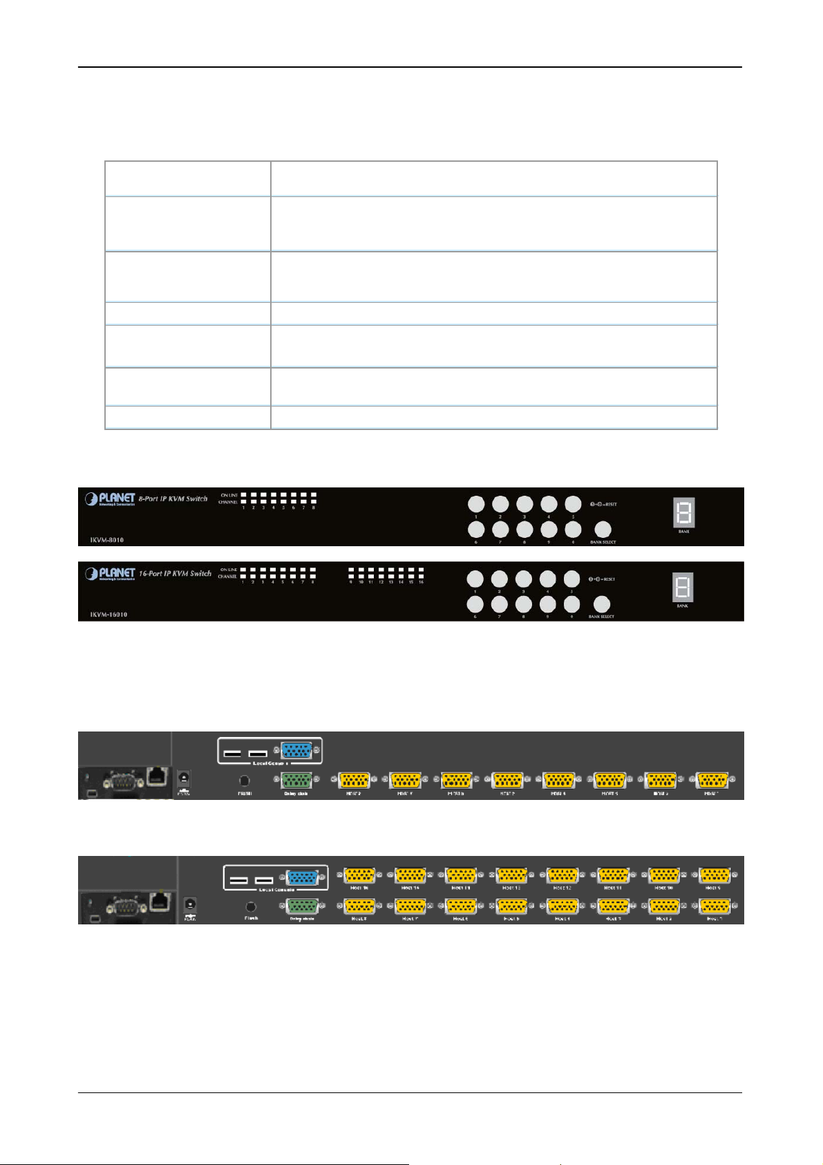
Front Panels of the Product Line
IKVM-8010 (8 ports combo VGA KVM switch with USB local console)
IKVM-16010 (16 ports combo VGA KVM switch with USB local console)
Back Panels of the Product line
7 / 38
Page 8
n
n
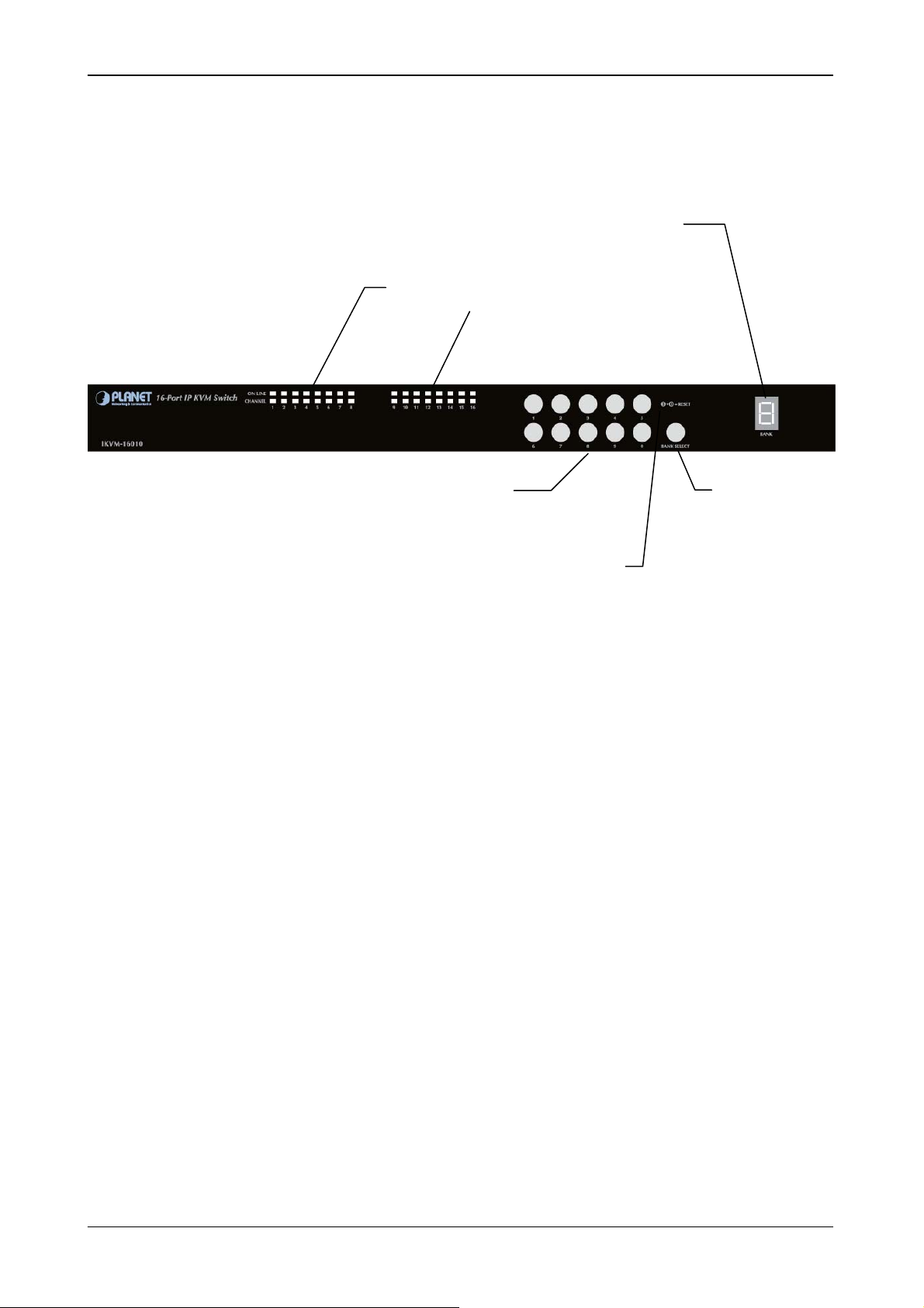
1.4 Front Panels
8/16-Port IP KVM Switch
1.5 Port LED Indications
7-seg LED for Bank Identificatio
LEDs for each Host Port
Port Number Select Button
ANK SELECT Button
Reset Butto
There are two LED’s for each port:
■
ONLINE LED: The Red LED on indicating a Computer is connecting to the port.
Notice: The PC99 Computer always power on the USB or PS/2 ports and turn on Red LED even if the
Computer is not power on.
■
SELECT LED: The Green LED on indicating the port has been selecting. The Green LED will be flashing
if there is no Computer connected to the port.
1.6 7-seg BANK LED
The 7-segment BANK LED indicates the selected bank. Maximum 8 banks can be daisy chai ned.
In the daisy chain configuration, there are two methods to select the bank (KVM unit) you want to operate:
Hotkey and OSD.
8 / 38
Page 9
8/16-Port IP KVM Switch
1.7 Buttons and Operations
There are 11 push buttons on the front panel. The operations described in below.
(1) The “BANK SELECT” is the Bank Select Button.
You can select to the required bank number by press the “BANK SELECT” button.
The current accessed bank will be displayed at the 7-Segment LED.
The bank select were from 1 to 8 and go back to 1 cycling. It will increase the bank number from the
current selected bank to the next bank if you pressed the “BANK SELECT” button once.
(2) The “1”, “2”, “3”, “4”, “5”, “6”, “7”, “8”, “9”, “0” are the port number select buttons
You can select to the required port number by
- Press the 2 digit port number to switch the port directly. For example if you are in port 1 now,
press “0” then “6” will switch to the port 6 immediately.
- Press the port number and wait for 2 seconds to switch the port. At this case, you can only
press single digit to select to the destination if the port number is between port 1 to port 9.
(3) If you pressed the invalid operation, the system will stay at the previous selected port.
(4) RESET: Press the “5” and “0” button simultaneously will restart the firmware of the IP KVM switch.
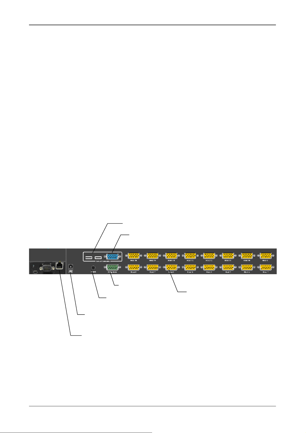
1.8 Back Panels
Flash Upgrade Port
DC Power Jack
Local Console Keyboard/Mouse Ports
Local Console VGA Port / Daisy Chain Out
Daisy Chain In
Connector for each Host Port
emote Console Port(CAT5 T-Module)
9 / 38
Page 10
8/16-Port IP KVM Switch
2 Hardware Installation
Before installation, please make sure all of peripherals and computers have been turned off.
2.1 Desktop or Rack Mount
The IKVM-8010 / IKVM-16010 switch unit can be placed on desktop or rack mounted.
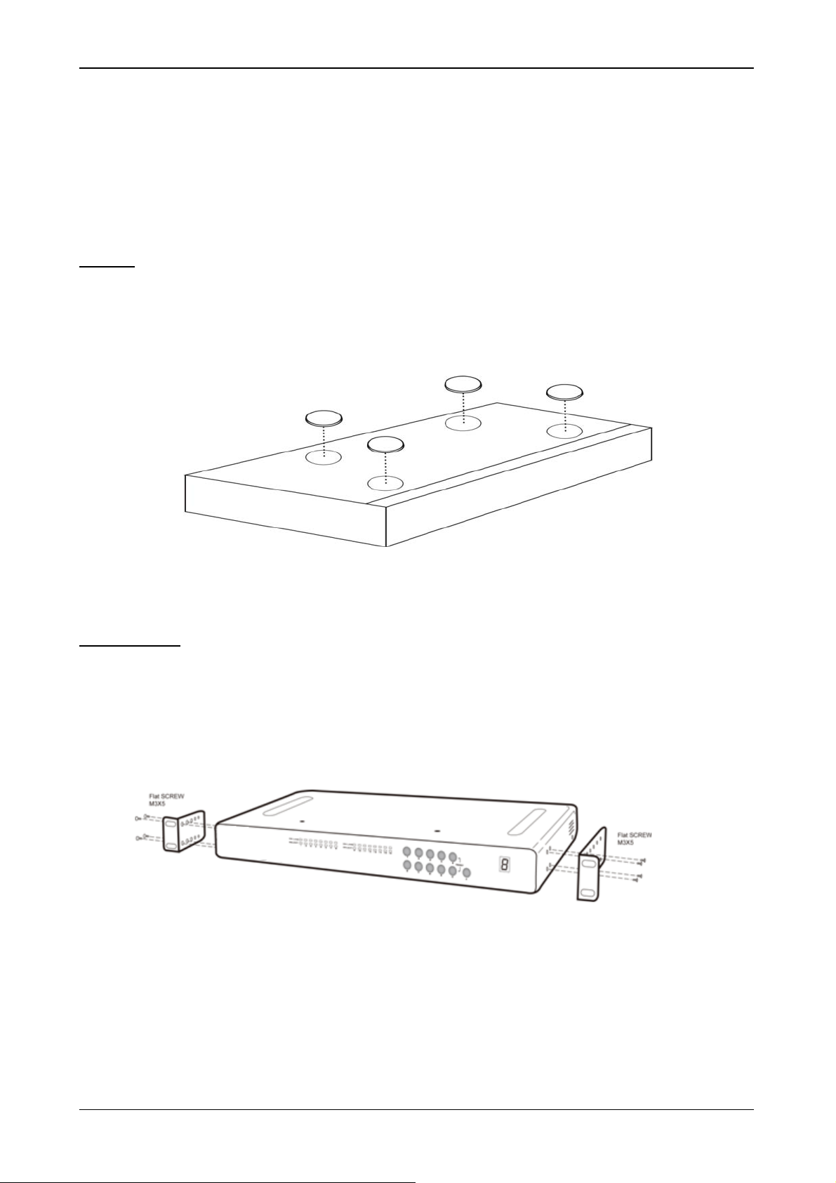
Desktop
Stick the self-adhesive footpads that come with the package to the unit’s bottom panel at the four corners. To
install footpads, please turn upside down; and refer to the following instructions properly for installing the
footpads.
Footpads Installation
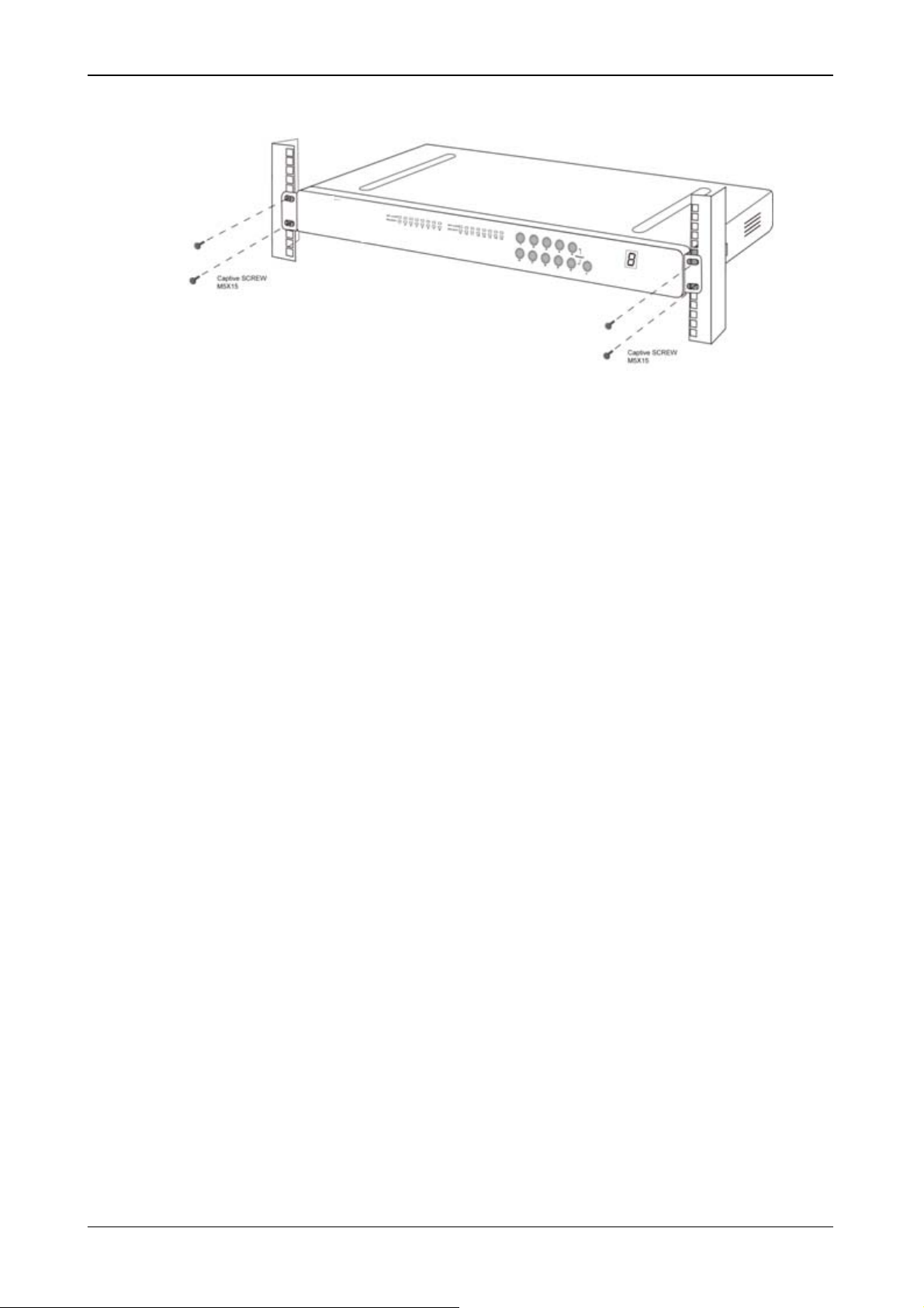
Rack Mounting
The IKVM-8010 / IKVM-16010 switch unit can be mounted on 19”/1U rack:
1. Screw the mounting brackets into the sides of the unit at the front, as shown in the diagram below.
Take note of the length of your cables so that your computers, IKVM-8010/16010 Switch, keyboard,
mouse and monitor are distanced properly.
Rack Mount Installation -1
2. Slide the unit into the rack and secure it to the rack.
10 / 38
Page 11
8/16-Port IP KVM Switch
Rack Mount Installation -2
11 / 38
Page 12
8/16-Port IP KVM Switch
2.2 Computer/Server Installation
2.2.1 CAT5 KVM on Host Side
Please refer to the “CAT5 Extender User Manual” for details. The figure below depicts the computer/server
installation.
Computer/Server Installation
12 / 38
Page 13

8/16-Port IP KVM Switch
2.2.2 3-in-1 VGA Cable Installation
Each computer port connector is HDDB15 type. The 3-in-1 VGA cable has a HDDB15 male conne ctor at one
end. Plug it into computer port on the rear of KVM switch. The other end of input cable has three connectors:
a HDDB15 male type for computer video, a purple mini din 6-pin PS/2 connector for keyboard and a green
mini din 6-pin PS/2 connector for mouse. Plug these three connectors into the respective ports of computer.
Repeat the same procedure for all other computers.
(a) PS/2 computer --- Plug in PS/2 mouse connector to computer mouse port, the PS/2 keyboard connector
to computer keyboard port. Do not hot plug PS/2 port. If you must do that make sure PS/2 mouse first
then the PS/2 keyboard.
3-in-1 VGA cable
(b) USB computer --- connect PS/2-USB changer to PS/2 keyboard connector, then plug the changer into
available USB port. This single USB port can communicate both keyboard and mouse signals. It works as a
standard HID (Human Interface Device), no extra driver needed.
PS/2-USB Changer
3-in-1 VGA Cable and PS/2 to USB Changer
Note:
It is recommended to power off all the computers and server before the installation. If we can
not turn off the computer, for PS/2 computer, please plug in T-dongle connectors in the
following order: firstly PS/2 mouse connector, secondly PS/2 keyboard connector, thirdly the
VGA connector to the computer.
13 / 38
Page 14

8/16-Port IP KVM Switch
2.3 Console Installation
2.3.1 Local Console
Connect the monitor to the HDDB15 female port on the back of the KVM unit labeled with the monitor symbol
at the Local Console connector.
There may be USB local console or PS/2 local console. For USB local console, connect the USB keyboard
to either one of USB local port and USB mouse to the other USB port. These USB ports are special designed
for keyboard and mouse, and can not work with USB hub or other USB devices. For PS/2 local console,
connect keyboard to purple PS/2 port and mouse to green PS/2 mouse port. There is a Daisy chain port
under VGA ports.
Local Console Installation
2.4 Optional Remote Console Installation
IP Module
Please refer to “IP KVM Module User Manual” for details.
IP Remote Console
Installation: Power off the KVM switch firstly. Remove the cover of the add-on slot, slide in the IP Module
and make sure the module is fully inserted into the slot.
The IP Module redirects local keyboard, mouse and video data to a remote administration console. It allows
you to control one or many computers locally at the server site or remotely via the Internet using a standard
browser.
14 / 38
Page 15

8/16-Port IP KVM Switch
IP-Module
Serial Power Control
The IP Module comes with a serial port for connecting to any serial device, such as serial PDU (Power
Distribution Unit) to provide remote power control, such as power on, power off, and power cycle for the
connected computers/servers.
2.4.1 CAT5 Transmitter Module
CAT5 Remote Console
Installation: Power off the KVM switch firstly. Remove the cover of the add-on slot, slide in the CAT5
transmitter module and make sure the module is fully inserted into the slot.
To extending your console up to 1000 feet away by connecting the CAT5 cable to the R-Box in the remote
end.
Please refer to the “CAT5 Extender User Manual” for details.
2.4.2 CAT5 KVM Receiver (R-Box)
Please refer to the “CAT5 Extender User Manual” for details.
15 / 38
Page 16

8/16-Port IP KVM Switch
2.5 Power Up Sequence
Double check whether all cables/connectors are properly connected. You can check the color of keyboard
and mouse connectors to ensure the connectors and cables are connected correctly.
The recommended Power Up sequence is as follows: Monitor, KVM Switch, finally the Computers.
Verify that all servers connected to the KVM Switch are powered on. If any connected servers have not been
powered on, it is okay to do so at this time (servers can be powered on simultaneously). The KVM Switch
emulates both a mouse and keyboard on each port and allows your server to boot normally.
When power on the KVM switch, you will see the SELECT LED of Port 1 lights up, and hear a beep sound. If
you encounter an error, check your cable connections for that server and reboot. If the problem persists,
please refer to the chapter “Troubleshooting” in this User Manual.
16 / 38
Page 17

8/16-Port IP KVM Switch
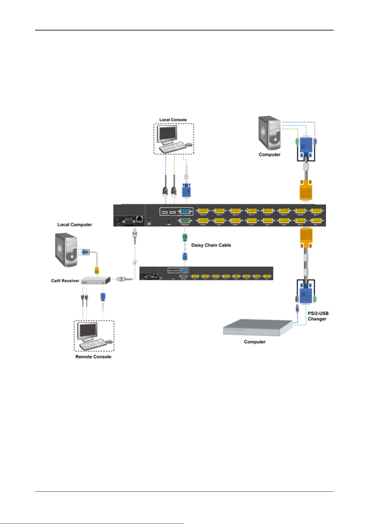
2.6 Daisy Chain Connection
Use one end of daisy chain cable to connect to the Daisy Chain port of Master KVM switch and connect the
other end of daisy chain cable to the Local Console port of the next Slave KVM switch. Please repeat the
connection procedures for next Slave KVM switch. You can daisy chain up to eight banks in maximum.
Note: The Daisy Chain cable is 15 lines fully connected. This is a special VGA cable, normal VGA
cable have unconnected lines.
Daisy Chain Connection
The console OSD menu will show only the port information of the master KVM switch. When the master unit
starts up, it will query all daisy chained Slave units, and automatically set up the Bank ID for each Slave unit.
So the 7-seg LED on the Master unit will display 1, Slave 1 will display 2, Slave 2 will display 3, and so on. If
not so, please reset the Master unit to update the Bank ID immediately. Hot Plug function is supported in
daisy chain connection.
17 / 38
Page 18

8/16-Port IP KVM Switch
You can also daisy chain through computer port. This daisy chain can work with other brand of KVM switch,
but you need to change the Hotkey of slave KVM switches so that the master and slave KVM switches do
not use the same Hotkey.
Daisy Chain through Computer Port
18 / 38
Page 19

8/16-Port IP KVM Switch
3 Usage
Now that you have connected your console and servers to your KVM Switch, it is ready for use.
You can control the KVM switch by three methods:
1. Using push buttons located on the front panel of the KVM Switch
2. Through the OSD (On-Screen Display)
3. Using hot-key commands through the console keyboard
It takes approximately 1-2 seconds for the video signal to refresh after switchin g servers. Re-synchronization
of the mouse and keyboard signals also occurs. This is normal operation and ensures that proper
synchronization is established between the console and the connected serve rs.
When you power on KVM switch, if the security function is enabled (default is disabled), it will prompt a Login
window waiting for user name and password. You need to pass the authentication so can control the KV M
switch.
3.1 Hotkey Commands and OSD Operations
Please refer to “Hotkey and OSD User Manual” for details.
3.2 DDC function
The KVM Switch support DDC (Display Data Channel). DDC is a VESA standard for communication
between a monitor and a video adapter. Using DDC, a monitor can inform the video card about its prop erties,
such as maximum resolution and color depth. The video card can then use this information to ensure that the
computer is presented with valid options for configuring the display.
Note: The DDC function of KVM Switch will dynamically detect and copy the DDC data from the
monitor that attached to the LOCAL console port, and that data will feed to the host
computer during computer startup.
3.3 Hot Plug
The KVM Switch supports “Hot Plug” function for USB keyboard and mouse connectors.
Note:
Normally, PS/2 port is not Hot pluggable. Normally, USB port is Hot pluggable, but some OS
(Operation Systems), like Sun Micro and some Unix and Linux, do not support USB Hot Plug
function. If you apply Hot Plug to this kind of OS, it will cause unpredictable behavior or shut
down the Computer. Before attempting to use Hot Plug, please make sure OS and mouse
software driver support the Hot Plug function
19 / 38
Page 20

8/16-Port IP KVM Switch
3.4 Firmware Upgrade
Please follow the following procedures:
1.
Power off the KVM switch.
2.
Prepare the DC2.5M/DB9F cable, plug the DC2.5 end to the KVM switch’s phone jack (marked Flash)
and the DB9F end to PC serial DB9 port.
3.
Power on the KVM unit. The KVM unit now will be in Flash mode, waiting for firmware download.
4.
Run “Firmware Upgrade Utility.exe”
5.
Click Browse to select the FW upgrade file. Please make sure you select the correct FW upgrade file.
6.
Click Write Flash to start to upgrade. The upgrade process takes about 6 seconds, then di splay WRITE
OK if complete the upgrade successfully.
7.
Disconnect the DC2.5M/DB9F cable from the KVM unit and PC. Now the KVM unit should be running
on the new firmware. The FW version can be seen on the bottom-right corner of the PORT NAME OSD
window.
20 / 38
Page 21

8/16-Port IP KVM Switch
4 Initial Configuration
4.1 Default Settings
The communication interfaces of IKVM-8010 / IKVM-16010 are all based on TCP/IP. It comes with the
default settings as below.
Parameter Value
IP-Address 192.168.1.1 (disabled)
Net-mask 255.255.255.0
Default-Gateway none
Super user name super
4.2 Configuration via Setup Utility
By default, the IKVM-8010 / IKVM-16010 will obtain its IP address from a DHCP server in the network. If a
Super user password pass
DHCP server is found, it may provide a valid IP address, gateway address and net mask. Before you
connect IKVM-8010 / IKVM-16010 to your local network, please make sure the corresponding configuration
of your DHCP server is completed. It is recommended to reserve a fixed IP assignment to the MAC address
of the IKVM-8010 /16010. You can find the MAC address labeled on the bottom side of the metal housing.
If this initial configuration does not meet your local requirements, use the setup tool to adjust the values to
your needs. The setup tool can be found on the CD-ROM delivered with this package. You can follow the
procedure described below.
1. Connect the IKVM-8010 / IKVM-16010 to the same network as your administrative PC, or you can use an
USB cable (type A to type B) to connect administrative PC and IKVM-8010 / IKVM-16010 directly. The
USB connectivity only supported in windows 2000/XP/Win7 and server 2003 and the response time of
USB connection would be longer than LAN connection.
2. Insert the bundled CD-ROM into the CD-ROM drive to initiate the auto run program. Click on “Setup Utility”
hyperlink in the menu screen to execute the program.
If the menu screen is not shown, you can click “Start” button and choose “Run…”. When the dialog box
appears, enter “E:\utility\psetup.exe” (suppose “E” is your CD-ROM drive) and click “OK”.
3. Once the utility is executed, it will search for available IKVM-8010 / IKVM-16010 automatically.
21 / 38
Page 22

8/16-Port IP KVM Switch
4. On the upper left corner, the MAC addresses of the IKVM-8010 / IKVM-16010 are displayed. To manually
detect the MAC address again, press the button “Refresh Devices”. The displayed MAC address is the
same MAC address printed on the sticker placed on the bottom of the IKVM-8010 /16010. If the
IKVM-8010 / IKVM-16010 are connected via USB, it is classified as an USB device and an appropriate
drive letter is chosen for this device.
5. On the lower right corner of the window, there are two buttons: “Query Device” and “Setup Device”. Press
the “Query Device” button to display the preconfigured values of the network configuration. The values are
displayed in the text fields located above. If necessary, adjust the network settings according to your
requirement. To save the changes, enter “super” in the “Super user login” field and “pass” in the “Super
user password” field. Then press the “Setup Device“ button.
6. On the lower left Authentication field, you can change the super user password here. However, the super
user name is fixed to “super” and can’t be modified. The default super user password is “pass”. It is
recommended to change the super user password as soon as you get this device.
The Wireless LAN Configuration field is left for future enhancement.
4.3 Configuration via Serial Port
Using a serial terminal, the IKVM-8010 / IKVM-16010 have a serial line interface (host side). This connector
is compliant with the RS-232 serial line standard. The serial line has to be configured with the parameters
given as below.
22 / 38
Page 23

8/16-Port IP KVM Switch
Parameter Value
Bits/second 115200
Data bits 8
Parity No
Stop bits
Flow Control None
1
When configuring with a serial terminal, press the reset button of IKVM-8010 / IKVM-16010 and immediately
press the “ ESC ” key on the keyboard of administrative PC. You will see some device information, and a
“ => ” prompt. There are four commands available.
config: start configuration tool after boot up
defaults: set the device settings to factory defaults
help: print online help
reset: perform a soft reset
When using “config” command, the following interactive options will appea r:
IP auto configuration (non/dhcp/bootp) [dhcp]:
With this option, you can specify whether the IKVM-8010 / IKVM-16010 should get its network
settings from a DHCP or BOOTP server. For DHCP, enter “dhcp”, and for BOOTP enter “bootp”. If
you do not specify any of these, the IP auto configuration is disabled and subsequently you will be
asked for the following network settings.
IP [192.168.1.1]:
This is the current IP address of the IKVM-8010 / IKVM-16010. This option is only available if IP
auto configuration is disabled.
Net mask [255.255.255.0]:
This is the net mask of the connected IP subnet. This option is only available if IP auto configuration
is disabled.
Gateway (0.0.0.0 for none) [0.0.0.0]:
This is the IP address of the default router for the connected IP subnet. If you do not have a default router,
enter 0.0.0.0. This option is only available if IP auto configuration is disabled.
4.4 Keyboard, Mouse, and Video Configuration
Between the IKVM-8010 / IKVM-16010 and the host, there are two interfaces available for transmitting
keyboard and mouse signals: USB and PS/2. The correct operation of the remote mouse depends on
several settings, which will be discussed in the following subsections.
4.4.1 Keyboard Settings
The IKVM-8010 / IKVM-16010 settings for the host's keyboard type must be corrected in order to make the
23 / 38
Page 24

8/16-Port IP KVM Switch
remote keyboard work properly. See Section 5.4.2 in details.
4.4.2 Remote Mouse Settings
A common issue with KVM devices is the synchronization between the local and remote mouse cursors. The
IKVM-8010 / IKVM-16010 address this situation with an intelligent synchronization algorithm. There are two
mouse modes available on the IKVM-8010 / IKVM-16010.
Auto mouse speed
The automatic mouse speed mode tries to detect the speed and acceleration settings of the host
system automatically. See the section below for a more detailed explanation.
Fixed mouse speed
This mode just translates the mouse movements from the Remote Console in a way that one pixel
move will lead to n pixel moves on the remote system. This parameter n is adjustable with the
scaling. It should be noted that this works only when mouse acceleration is turned off on the remote
system.
4.4.3 Auto Mouse Speed and Mouse Synchronization
The automatic mouse speed mode performs the speed detection during mouse synchronization. Whenever
the mouse does not move correctly, there are two ways for re-synchronizing local and remote mouse:
Fast Sync
The fast synchronization is used to correct a temporary, but fixed skew. Choose the option using
the Remote Console options menu or press the mouse synchronization hotkey sequence if you
already defined one.
Intelligent Sync
If the fast sync does not work or the mouse settings have been changed on the host system, use
the intelligent resynchronization. This method takes more time than Fast Sync and can be
accessed with the appropriate item in the Remote Console option menu. The intelligent
synchronization requires a correctly adjusted picture. Use the auto adjustment function or the
manual correction in the Video Settings panel to setup the picture. The Sync mouse button on top
of the Remote Console may behave differently, depending on the current state of mouse
synchronization. Usually pressing this button leads to a fast sync, except in situations where the
KVM port or the video mode changed recently.
Note:
At first start, if the local mouse pointer is not synchronized with the remote mouse pointer,
press the Auto Adjust Button once.
4 .4.4 Host System Mouse Settings
While the IKVM-8010 / IKVM-16010 works with accelerated mice and are able to synchronize the local with
the remote mouse pointer, there are the following limitations, which may prevent this synchronization from
working properly: (the following limitations do not apply in case of USB and Mouse Type “MS Windows 2000
and newer”.)
24 / 38
Page 25

8/16-Port IP KVM Switch
Special Mouse Driver
There are mouse drivers that influence the synchronization process and lead to desynchronized
mouse pointers. If this happens, make sure you do not use a special vendor-specific mouse
driver on your host system.
Windows XP Mouse Settings
Windows XP knows a setting named “improve mouse acceleration”, which has to be dea ctivated.
Active Desktop
If the Active Desktop feature of Microsoft Windows is enabled, do not use a plain background.
Instead, use some kind of wallpaper. As an alternative, you could also disable the Active Desktop
completely.
Navigate your mouse pointer into the upper left corner of the applet screen and move it slightly
forth and back. Thus the mouse will be resynchronized. If re-synchronizing fails, disable the
mouse acceleration and repeat the procedure.
4.4.5 Single and Double Mouse Mode
The information above applies to the Double Mouse Mode, where remote and local mouse pointers are
visible and need to be synchronized. The IKVM-8010 / IKVM-16010 also feature another mode, the Single
Mouse Mode, where only the remote mouse pointer is visible. Activate this mode in the open Remote
Console and click into the window area. The local mouse pointer will be hidden and the remote one can be
controlled directly. To leave this mode, it is necessary to define a mouse hotkey in the Remote Console
Settings Panel. Press this hotkey to free the captured local mouse pointer.
4.4.6 Recommended Mouse Settings
For the different operating systems we can give the following advice:
MS Windows 2000/XP/2003/Win7 (Professional and Server)
In general, we recommend the usage of a mouse via USB. Choose USB without Mouse Sync. For
a PS/2 mouse, choose Auto Mouse Speed. For XP disable the option enhances pointer precision in
the Control Panel.
SUN Solaris
Adjust the mouse settings either via xset m 1 or use the CDE Control Panel to set the mouse to 1:1,
no acceleration. As an alternative you may also use the Single Mouse Mode.
MAC OS X
We recommend using the Single Mouse Mode.
4.4.7 Video Modes
The IKVM-8010 / IKVM-16010 recognize a limited number of common video modes. When running X11 on
the host system, please do not use any custom mode lines with special video modes. If you do, the
IKVM-8010 /16010 may not be able to detect them. We recommend using any of the standard VESA video
modes, instead.
25 / 38
Page 26

8/16-Port IP KVM Switch
5 Remote Usage
5.1 Prerequisite
The IKVM-8010 / IKVM-16010 feature an embedded operating system and applications offering a variety of
standardized interfaces. This chapter will describe both these interfaces, and the way to use them in a more
detailed manner. The interfaces are accessed using the TCP/IP protocol family, thus they can be accessed
using the built-in Ethernet port.
The following interfaces are supported:
HTTP/HTTPS
The IKVM-8010 / IKVM-16010 can be entirely managed using a standard web browser. You can
access the IKVM-8010 /16010 using the insecure HTTP protocol, or using the encrypted HTTPS
protocol. Whenever possible, use HTTPS.
Telnet
A standard Telnet client can be used to access an arbitrary device connected to the IKVM-8010 /
IKVM-16010 port via a terminal mode.
The primary interface of the IKVM-8010 / IKVM-16010 is the HTTP interface. This is covered extensively in
this chapter. Other interfaces are addressed in subtopics.
In order to use the Remote Console window of your managed host system, the browser has to come with a
Java Runtime Environment version 1.1 or higher. If the browser has no Java support (such as on a small
handheld device), you are still able to maintain your remote host system using the administration forms
displayed by the browser itself.
Important: We recommend installing a Sun JVM 1.4.
For an insecure connection to the IKVM-8010 / IKVM-16010, we can recommend the following browsers:
• Microsoft Internet Explorer version 6.0 or higher on Windows 98, Windows ME, Windows 2000,
Windows XP, Windows Server 2003 and Win7.
• Netscape Navigator 7.0 or Mozilla 1.6 on Windows 98, Windows ME, Windows 2000, Windows XP,
Windows Server 2003, Win7 and Linux and other UNIX-like Operating Systems
In order to access the remote host system using a securely encrypted connection, you need a browser that
supports the HTTPS protocol. Strong security is only assured by using a key length of 128 Bit. Some of the
old browsers do not have a strong 128 Bit encryption algorithm.
Using the Internet Explorer, open the menu entry “?” and “Info” to read about the key length that is currently
activated. The dialog box contains a link that leads you to information on how to upgrade your browser to a
state of the art encryption scheme. The picture below shows the dialog box presented by the Internet
Explorer 6.0.
26 / 38
Page 27

Newer web browsers do support strong encryption on default.
5.2 Login and Logout
5.2.1 Login
8/16-Port IP KVM Switch
Note:
Launch your web browser. Direct it to the address of your IKVM-8010 / IKVM-16010, which you configured
during the initial configuration. The address used might be a plain IP address or a host and domain name, in
the case where you have given your IKVM-8010 / IKVM-16010 a symbolic name in the DNS. For instance,
type the following in the address line of your browser when establishing an unsecured connection:
When using a secure connection, type in:
This will lead you to the IKVM-8010 / IKVM-16010 login page.
Your web browser has to accept cookies, or else login is not possible.
http://<IP address of IKVM-8010 / IKVM-16010 >
https://<IP address of IKVM-8010 / IKVM-16010>
The IKVM-8010 / IKVM-16010 have a built-in super user that has all permissions to administrate the device:
Login name
Password
super (in default)
pass (in default)
Warning: The user “super” is not allowed to login via the serial interface of the IKVM-8010 / IKVM-16010.
Note:
Please change the super user password immediately after the first time login successfully. Not
changing the pass phrase for the super user is a severe security risk and might result in
unauthorized access to the IKVM-8010 / IKVM-16010 and to the host system including all possible
consequences!
27 / 38
Page 28

8/16-Port IP KVM Switch
Having logged into the IKVM-8010 / IKVM-16010 successfully, the main page of the IKVM-8010 /
IKVM-16010 will appear.
This page consists of three parts; each of them contains specific information. The buttons on the upper side
allow you to navigate within the front end.
Return to the main page of the IKVM-8010 /
IKVM-16010 .
Open the IKVM-8010 / IKVM-16010 remote console.
Exit from the IKVM-8010 / IKVM-16010 front end.
The lower left frame contains a navigation bar and allows you to switch between the different sections of the
IKVM-8010 / IKVM-16010. Within the right frame, task-specific information is displayed that depends on the
section you have chosen before.
Warning: If there is no activity for half an hour, the IKVM-8010 /16010 will log you out, automatically. A click
on one of the links will bring you back to the login screen.
5.2.2 Logout
This button
logout will be performed in case there is no activity for half an hour.
logs out the current user and presents a new login screen. Please note that an automatic
28 / 38
Page 29

5.2.3 The Remote Console
8/16-Port IP KVM Switch
Clicking on the icon
Java Applet that tries to establish its own TCP connection to the IKVM-8010 /16010. The protocol that is run
over this connection is neither HTTP nor HTTPS, but RFB (Remote Frame Buffer Protocol). Currently, RFB
tries to establish a connection to port number 443. Your local network environment has to allow this
connection to be made, i.e. your firewall end, in case you have a private internal network, your NAT (Network
Address Translation) settings have to be configured accordingly.
In case the IKVM-8010 /16010 are connected to your local network environment and your connection to the
Internet is available using a proxy server only without NAT being configured, the Remote Console is very
unlikely to be able to establish the according connection. This is because today's web proxies are not
capable of relaying the RFB protocol.
In case of problems, please consult your network administrator in order to provide an appropriate network
environment.
Once the Remote Console is connected, it displays the screen content of your host system. The Remote
Console will behave exactly in the same way as if you were sitting directly in front of the screen of your
remote system. That means keyboard and mouse can be used in the usual way. However, be aware of the
fact that the remote system will react to keyboard and mouse actions with a slight delay. The delay depends
opens an additional Remote Console window. The Remote Console window is a
on the bandwidth of the network which you use to connect to the IKVM-8010 / IKVM-16010.
With respect to the keyboard, the very exact remote representation might lead to some confusion as you r
local keyboard changes its keyboard layout according to the remote host system. If you use a German
administration system, and your host system uses a US English keyboard layout, for instance, special keys
on the German keyboard will not work as expected. Instead, the keys will result in their US English
counterpart. You can circumvent such problems by adjusting the keyboard of your remote system to the
same mapping as your local one.
The Remote Console window always tries to show the remote screen with its optimal size. That means it will
adapt its size to the size of the remote screen initially and after the screen resolution of the remote screen
has been changed. However, you can always resize the Remote Console window in your local window
system as usual.
5.2.4 Remote Console Control Bar
The upper part of the Remote Console window contains a control bar. Using its elements you can see the
state of the Remote Console and influence the local Remote Console settings. A description for each control
follows.
29 / 38
Page 30

8/16-Port IP KVM Switch
Control Bar
Status Line
Special button to send the “Control+Alt+Delete” key combination to the remote system.
Auto Adjust Button
If the video display is of bad quality or distorted in some way, press this button and wait a few seconds while
the IKVM-8010 / IKVM-16010 tries to adjust itself for the best possible video quality.
Mouse Synchronize Button
Pressing this button to activate the mouse synchronization process. Choose this option in order to
synchronize the local with the remote mouse cursor. This is especially necessary when using accelerated
mouse settings on the host system. In general, there is no need to change mouse settings on the host.
Switches between the Single Mouse Mode (where only the remote mouse pointer is visible) and the Double
Single/Double Mouse Mode
Mouse Mode (where remote and local mouse pointers are visible and need to be synchronized). Single
mouse mode is only available if using SUN JVM 1.3 or higher.
30 / 38
Page 31

Click on this button, an Options menu will appear:
8/16-Port IP KVM Switch
A short description of the options follows.
• Monitor Only
Toggles the Monitor only filter on or off. If the filter is switched on, no remote console interaction is
possible, and monitoring is possible.
• Exclusive Access
If a user has the appropriate permission, he can force the Remote Consoles of all other users to close.
No one can open the Remote Console at the same time again until this user disables the exclusive
access, or logs off.
A change in the access mode is also visible in the status line.
• Scaling
Allow you to scale down the Remote Console. You can still use both mouse and keyboard, however the
scaling algorithm will not preserve all display details.
31 / 38
Page 32

8/16-Port IP KVM Switch
• Mouse Handling
The submenu for mouse handling offers two options for synchronizing the local and the remote mouse
pointer.
Fast Sync--The fast synchronization is used to correct a temporary, but fixed skew.
Intelligent Sync--Use this option if the fast sync does not work or the mouse settings have been
changed on the host system.
This method takes more time than the fast one and requires a correctly adjusted picture. Use the auto
adjustment function or the manual correction in the Video Settings panel to setup the picture.
• Local Cursor
Offers a list of different curs or shapes to choose from for the lo cal mouse pointer. The select ed shape
will be saved for the current user and activated the next time this user opens the Remote Console. The
number of available shapes depends on the Java Virtual Machine; a version of 1.2 or higher offers the
full list.
32 / 38
Page 33

• Video Settings
Opens a panel for changing the IKVM-8010 / IKVM-16010 video settings.
Brightness--Controls the brightness of the picture.
Contrast--Controls the contrast of the picture.
8/16-Port IP KVM Switch
Clock--Defines the horizontal frequency for a video line and depends on the video mode. Different
video card types may require different values here. The default settings in conjuction with the auto
adjustment procedure should be adequate for all common configurations. If the picture quality is still
bad after auto adjustment, you may try to change this setting together with the sampling phase to
achieve a better quality.
Phase--Defines the phase for video sampling, used to control the display quality together with the
setting for sampling clock.
Horizontal Position--Use the left and right buttons to move the picture in horizontal direction while this
option is selected.
Vertical Position--Use the left and right buttons to move the picture in vertical direction while this option
is selected.
Reset this Mode--Reset mode specific settings to the factory-made defaults.
Reset all Modes--Reset all settings to the factory-made defaults.
Save Changes--Save changes permanently.
Undo Changes--Restore last settings.
33 / 38
Page 34

8/16-Port IP KVM Switch
• Soft Keyboard
Opens up the Menu for the Soft-Keyboard.
Show--Pops up the Soft-Keyboard. The Soft-Keyboard is necessary in case your host system runs a
completely different language and country mapping than your administration machine.
Mapping--Used for choosing the according language and country mapping of the Soft-Keyboard.
• Local Keyboard
Used to change the language mapping of your browser machine running the Remote Console Applet.
Normally, the applet determines the correct value automatically. However, depending on your particular
JVM and your browser settings this is not always possible. A typical example is a German localized
system that uses an US-English keyboard mapping. In this case you have to change the Local
Keyboard setting to the right language, manually.
• Hotkeys
Opens a list of hotkeys defined previously. Choose one entry, the command will be sent to the host
system.
A confirmation dialog can be added that will be displayed before sending the selected command to the
remote host. Select “OK” to perform the command on the remote host.
5.2.5 Remote Console Status Line
The Remote Console Status Bar shows both console and the connection state. The size of the remote
screen is displayed. The value in brackets describes the connection to the Remote Console. “Norm” means a
standard connection without encryption, “SSL” indicates a secure connection.
Furthermore, both the incoming (“In:”) and the outgoing (“Out:”) network traffic are visible (in B/s). If
compressed encoding is enabled, a value in brackets displays the compressed transfer rate.
34 / 38
Page 35

Appendix A Cable Connectors Specifications
Cable Connectors
1. 3-in-1 VGA Cable
HDDB15 male to one HDDB15 male plus two minis din 6-pin PS/2 connectors.
3-in-1 VGA Cable Connectors
2. PS/2 keyboard to USB Changer
PS/2 (keyboard) to USB (keyboard and mouse) changer.
8/16-Port IP KVM Switch
3. Daisy Chain Cable
VGA Cable: HDDB15 Male to Male
Note:
Daisy chain needs the cable 15 lines fully connected. This is a special VGA cable, normal
VGA cable have unconnected lines. Please contract your dealer for Daisy chain cable.
PS/2 keyboard to USB Changer
Daisy Chain Cable
35 / 38
Page 36

8/16-Port IP KVM Switch
Appendix B Troubleshooting & Frequently Asked Questions
Question Answer
Make sure the mouse settings in IKVM-8010 / IKVM-16010 match the
The remote mouse doesn’t
work or is not synchronous
The video quality is bad or the
picture is grainy
Login on IKVM-8010 /
IKVM-16010 fails.
mouse model. There are some circumstances where the mouse
synchronization process could behave incorrectly, refer to Section 3.4.3 for
further explanation.
Try to correct the brightness and contrast settings (see section 4.3.1) until
they are out of a range where the picture looks grainy. Use the auto
adjustment feature to correct a flickering video.
Was the correct combination of user and password given? On delivery, the
user ”super” has the password ”pass”. Moreover your browser must be
configured to accept cookies.
The Remote Console window
can’t connect to IKVM-8010 /
IKVM-16010.
No connection can be
established to IKVM-8010 /
IKVM-16010.
Special key combinations, e.g.
ALT+F2, ALT+F3 are
intercepted by the console
system and not transmitted to
the host.
In the browser the IKVM-8010 /
IKVM-16010 pages are
inconsistent or chaotic.
Possibly a firewall prevents access to the Remote Console. Make sure the
TCP port numbers 443 or 80 are open for incoming TCP connection
establishments.
Check whether the network connection is working in general (ping the IP
address of IKVM-8010 / IKVM-16010). If not, check network hardware. Is
IKVM-8010 powered on? Check whether the IP address of IKVM-8010 /
IKVM-16010 and all other IP related settings are correct! Also verify that all
the IP infrastructure of your LAN, like routers etc., is correctly configured.
Without a ping functioning, IKVM-8010 / IKVM-16010 can’t work either.
You have to define a so-called ’Button Key’. This can be done in the Remote
Console settings.
Make sure your browser cache settings are feasible. Especially make sure
the cache settings are not set to something like ”never check for newer
pages”. Otherwise IKVM-8010 / IKVM-16010 pages may be loaded from
your browser cache and not from the card.
Windows XP doesn’t awake
from standby mode
Can’t upload the signed
certificate in MacOS X
Every time I open a dialog box
with some buttons the mouse
pointers are not synchronous
anymore
This is possibly a Windows XP problem. Try not to move the mouse while
XP goes in standby mode.
If an ’internal error’ occurs while uploading the signed certificate, either
change the extension of the file to .txt or add a file helper using the Internet
Explorer preferences for this type of file. Make sure that the encoding is
plain text and the checkbox ’use for outgoing’ is checked. Another possibility
is to use a Mozilla based browser.
Please check, if you have an option like ”‘Automatically move mouse pointer
to the default button of dialog boxes”’ enabled in the mouse settings of the
operating system. This option needs to be disabled.
36 / 38
Page 37

Appendix C Specifications
8/16-Port IP KVM Switch
Feature
Model
Host Port Connector
Host Ports
Console Type
Max. Distance (KVM switch --
Host)
Video Resolution(Local Console) 1920 x 1440
Video Resolution(Remote
Console)
Console Ports
Flash Port
CAT5-Based Remote Module RJ-45 Connector
IP-Based Remote
Module
Daisy Chain
Computers Selection
Hotkey
Computer Port LED’s
7-seg LED
Security
Multilingual OSD (On Screen
Display) control
Auto-Scan Intervals
Keyboard Emulation
Mouse Emulation
Max. Connected Computers
Housing
Power DC Power adapter : 12V, 1A
Operation Temperature
Storage Temperature
Humidity 0~80%, Non-Condensing
Mechanical 19” Rackmount, 1U
Dimension (mm) 444.5 * 160 * 44.3
Specification
IKVM-8010
VGA
8
USB or PS/2
16 feet (5m)
1680 x 1050 for CAT5-Based 500 feet remote console
1280 x 1024 for CAT5-Based 1000 feet remote console
1600 x 1200 for IP-Based remote console
1 Local console, plus
1 Optional Modules: CAT5-Based or IP-Based Remote Console
DC2.5F
CAT5 console up to 1000 feet away from KVM switch with superior
auto-adjust RGB signals capability
RJ-45 8P8C for 10/100M Ethernet
DB-9 male for Configuration console, Modem, Null modem, and serial
power control
Mini USB 2.0 receptacle
Support Daisy Chaining with both Bus (8-layer) and Tree (2-layer)
topologies
Connector DB15 (Female Type)
On Screen Display (OSD) Menu, Hot Key, Push Button
Provide various Hotkey (Scroll-Lock/ Caps-Lock/ Num-Lock/ Alt/ Ctrl/ Win)
2 LED’s per Host port: ON LINE (Red), SELECT (Green)
1 set for Bank display
Provide ACL (Access Control List) security function, store up to 8
independent ACL’s of controllable computer lists
8 languages (English, France, Germen, Spanish, Italian, Russian,
Japanese, Simplified Chinese)
5 ~ 99 Sec.
PS/2 or USB
PS/2 or USB
Up to 8192
Metal
0 ~ 50℃
-20 ~ 60℃
37 / 38
Page 38

8/16-Port IP KVM Switch
Feature
Model
Host Port Connector
Host Ports
Console Type
Max. Distance (KVM switch --
Host)
Video Resolution(Local
Console)
Video Resolution(Remote
Console)
Console Ports
Flash Port
CAT5-Based Remote Module RJ-45 Connector
IP-Based Remote
Module
Daisy Chain
Computers Selection
Hotkey
Computer Port LED’s
7-seg LED
Security
Multilingual OSD (On Screen
Display) control
Auto-Scan Intervals
Keyboard Emulation
Specification
IKVM-16010
VGA
16
USB or PS/2
16 feet (5m)
1920 x 1440
1680 x 1050 for CAT5-Based 500 feet remote console
1280 x 1024 for CAT5-Based 1000 feet remote console
1600 x 1200 for IP-Based remote console
1 Local console, plus
1 Optional Modules: CAT5-Based or IP-Based Remote Console
DC2.5F
CAT5 console up to 1000 feet away from KVM switch with superior
auto-adjust RGB signals capability
RJ-45 8P8C for 10/100M Ethernet
DB-9 male for Configuration console, Modem, Null modem, and serial
power control
Mini USB 2.0 receptacle
Support Daisy Chaining with both Bus (8-layer) and Tree (2-layer)
topologies
Connector DB15 (Female Type)
On Screen Display (OSD) Menu, Hot Key, Push Button
Provide various Hotkey (Scroll-Lock/ Caps-Lock/ Num-Lock/ Alt/ Ctrl/ Win)
2 LED’s per Host port: ON LINE (Red), SELECT (Green)
1 set for Bank display
Provide ACL (Access Control List) security function, store up to 8
independent ACL’s of controllable computer lists
8 languages (English, France, Germen, Spanish, Italian, Russian,
Japanese, Simplified Chinese)
5 ~ 99 Sec.
PS/2 or USB
Mouse Emulation
Max. Connected Computers Up to 8192
Housing
Power DC Power adapter : 12V, 1A
Operation Temperature 0 ~ 50℃
Storage Temperature -20 ~ 60℃
Humidity 0~80%, Non-Condensing
Mechanical 19” Rackmount, 1U
Dimension (mm) 444.5 * 160 * 44.3
PS/2 or USB
Metal
38 / 38
 Loading...