

Page 1
Page 2
Verify The Contents Inside Package Box
The package should contain the following items plus IHD-210 series. If
any item is missing or damaged, please contact the seller immediately.
Quick Installation Guide
IR Emitter Cable
(Comes with Transmitter)
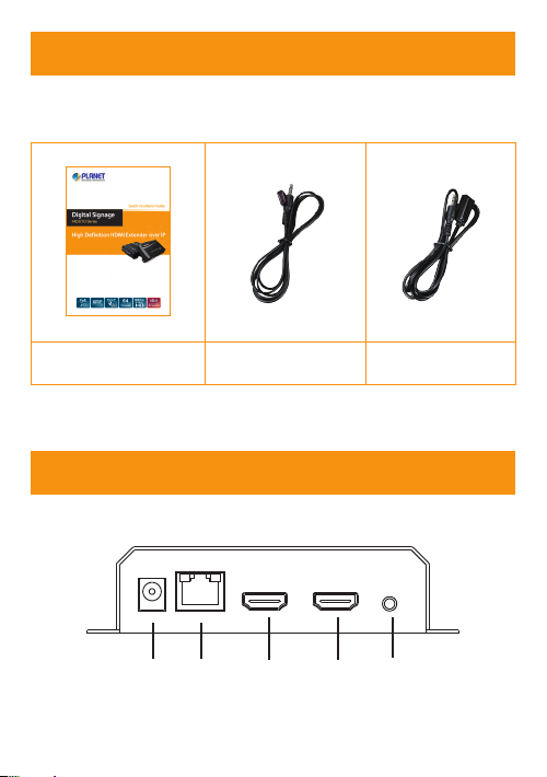
Product Outlook & Functions
1 2 3 4 5
– 1 –
IR Receiver Cable
(Comes with Receiver)
Page 3
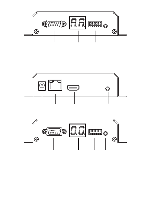
6 7 8 9
Transmitter (IHD-210PT)
1 2 3 5
6 7 8 9
Receiver (IHD-210PR)
– 2 –
Page 4

Position Description Function
1 DC 5V
Ethernet
2
3 HDMI Out
4 HDMI In
5 IR
6 RS-232
7 Channel Display group indication.
8 Group
9 Reset
(PoE)
5V/2A DC power input.
Only use one power source, either from DC
or from 802.3af/at PoE+ Ethernet switch.
Connect to a LAN Switch.
IGMP snooping and Jumbo Frame
supported Gigabit IEEE 802.3af/at PoE+
Ethernet switch is recommended.
LED:
1. LAN LED (green color):
This LED will be ashing while network is
accessing via Ethernet.
2. Power LED (orange color):
When the device is powered on, and the
device is connected to Ethernet switch,
the LED will be always on.
HDMI Type-A female connector for video
output.
HDMI Type-A female connector for
connecting to the HDMI source. (Only built-in
on Transmitter)
Transmitter: 3.5mm jack for IR emitter cable
to control video source device.
Receiver: 3.5mm jack for IR receiver cable
to receive signal from remote controller.
DB-9 female connector for RS-232
bi-directional remote extension.
Group conguration, 6-bit switch for 64
stream channel selection.
Power on the device and press the reset
button for over one second to restore it to
factory default settings.
– 3 –
Page 5

Installation
1. Connect the video source to the Transmitter/Sender (IHD-210PT)
Unit’s HDMI In interface.
2. Connect the monitor to the Receiver (IHD-210PR) Unit’s HDMI Out
interface.
3. Use Cat5e/6 cables (EIA/TIA 568B industry standard compliant) for
connection between Transmitter/Receiver and the IEEE 802.3af/at
PoE+ switch.
4. Set an identical ID number on DIP switch for all units of the same
group.
5. Apply the proper power to all connecting devices.
It is suggested using the Gigabit IEEE 802.3af/
at PoE+ Ethernet switch with IGMP snooping and
Jumbo Frame to ensure optimal transmission quality.
If users encounter no screen display in computer
connection:
1. Make sure the device cables are correctly and
rmly attached.
Note
2. Set your display device’s (TV, monitor, etc.) input
source as HDMI.
3. Check the PC BIOS conguration about the video
output setting.
4. Connect your computer to the HDMI Display
DIRECTLY to check if the video signal gets
through.
– 4 –
Page 6

Connection Pattern
* More PoE switches and RXs (Receivers) can be used to distribute a single video signal to multi-monitors.
Video Extender
1. Video Extender: Point to Point
Input Source Output Source
Video Source
IHD-210PT
HDMI HDMI
IHD-210PR
2. Video Extender: Multicasting
Video Extender
Video Source
IHD-210PT
(ID: 00)
IHD-210PT
(ID: 01)
IHD-210PT
(ID: 02)
PoE
PoE
Gigabit PoE Switch
(with IGMP Snooping
and Jumbo Frame)
PoE
IHD-210PR
IHD-210PR
PoE PoE
(ID: 01)
PoE PoE PoE
IHD-210PR
(ID: 02)
IHD-210PR
(ID: 01)
(ID: 00)
PC
DVD Player
Blu-ray Player
HDMI
PoE
100BASE-T UTP with PoE
Video Extender: Many to Many
– 5 – – 6 –
IHD-210PT
IHD-210PR
(ID: 02)
Video Extender
Link
100BASE-TX UTP
STEP 3STEP 1 STEP 2
IHD-210PR
IHD-210PR
(ID: 00)
PoE
Page 7

Further Conguration
For detailed conguration, please refer to user manual downloadable
from the web site (http://www.planet.com.tw/en/support/download.php).
Utility User’s Manual
If you have any other question, please contact the dealer where
you purchased this product or you can contact PLANET directly at the
following email address: support@planet.com.tw
Page 8

 Loading...