

Page 1

Trademarks
Copyright © PLANET Technology Corp. 2006.
Contents subject to revision without prior notice.
PLANET is a registered trademark of PLANET Technology Corp. All other trademarks belong to their respective
owners.
Disclaimer
PLANET Technology does not warrant that the hardware will work properly in all environments and applications,
and makes no warranty and representation, either implied or expressed, with respect to the quality, performance,
merchantability, or fitness for a particular purpose.
PLANET has made every effort to ensure that this User’s Manual is accurate; PLANET disclaims liability for any
inaccuracies or omissions that may have occurred.
Information in this User’s Manual is subject to change without notice and does not represent a commitment on the
part of PLANET. PLANET assumes no responsibility for any inaccuracies that may be contained in this User’s
Manual. PLANET makes no commitment to update or keep current the information in this User’s Manual, and
reserves the right to make improvements to this User’s Manual and/or to the products described in this User’s
Manual, at any time without notice.
If you find information in this manual that is incorrect, misleading, or incomplete, we would appreciate your
comments and suggestions.
FCC Warning
This equipment has been tested and found to comply with the limits for a Class A digital device, pursuant to Part 15
of the FCC Rules. These limits are designed to provide reasonable protection against harmful interference when
the equipment is operated in a commercial environment. This equipment generates, uses, and can radiate radio
frequency energy and, if not installed and used in accordance with the Instruction manual, may cause harmful
interference to radio communications. Operation of this equipment in a residential area is likely to cause harmful
interference in which case the user will be required to correct the interference at his own expense.
CE Mark Warning
This is a Class A product. In a domestic environment, this product may cause radio interference, in which case the
user may be required to take adequate measures.
WEEE Warning
To avoid the potential effects on the environment and human health as a result of the presence of
hazardous substances in electrical and electronic equipment, end users of electrical and electronic
equipment should understand the meaning of the crossed-out wheeled bin symbol. Do not dispose of
WEEE as unsorted municipal waste and have to collect such WEEE separately.
Revision
PLANET 24-Port 10/100Mbps + 1-Slot Web Smart Fast Ethernet Switch User's Manual
FOR MODEL: FNSW-2401CS
REVISION: 2.0(JUNE.2006)
Part No: EM_FNSW2401CSv2 (2010-A81110-001)
- 1 -
Page 2

TABLE OF CONTENTS
1. INTRODUCTION..........................................................................................................................................3
1.1 CHECKLIST ................................................................................................................................................................3
1.2 ABOUT THE SWITCH ..................................................................................................................................................3
1.3 FEATURES..................................................................................................................................................................4
1.4 SPECIFICATION .......................................................................................................................................................... 4
2. HARDWARE DESCRIPTION.......................................................................................................................6
2.1 FRONT PANEL............................................................................................................................................................ 6
2.2 REAR PANEL..............................................................................................................................................................6
2.3 HARDWARE INSTALLATION .......................................................................................................................................7
3. SWITCH MANAGEMENT............................................................................................................................9
3.1 OVERVIEW.................................................................................................................................................................9
3.2 MANAGEMENT METHOD............................................................................................................................................9
3.2.1 Web Management..............................................................................................................................................9
3.3 LOGGING ON TO THE FNSW-2401CS........................................................................................................................ 9
4. WEB MANAGEMENT.................................................................................................................................10
4.1 LOGIN IN TO THE SWITCH.........................................................................................................................................10
4-2 PORT CONFIG ..........................................................................................................................................................11
4-3 VLAN SETUP..........................................................................................................................................................12
4.3.1 VLAN setting example:....................................................................................................................................13
4-4 PORT TRUNK SETUP ................................................................................................................................................14
4-5 PORT MIRROR SETUP ..............................................................................................................................................15
4-6 STATUS....................................................................................................................................................................16
4.6.1 System Information..........................................................................................................................................17
4.6.2 Port Status.......................................................................................................................................................18
4-7 MISC CONFIGURATION ............................................................................................................................................19
4.7.1 IP Address .......................................................................................................................................................20
4.7.2 Password ......................................................................................................................................................... 21
4.7.3 Switch Control.................................................................................................................................................22
4-8 TOOLS .....................................................................................................................................................................23
4.8.1 Reboot.............................................................................................................................................................. 24
4.8.2 Factory Reset...................................................................................................................................................25
4.8.3 Firmware Upgrade..........................................................................................................................................27
4-9 LOGOUT .................................................................................................................................................................. 31
5. SWITCH OPERATION................................................................................................................................33
5.1 ADDRESS TABLE...................................................................................................................................................... 33
5.2 LEARNING................................................................................................................................................................33
5.3 FORWARDING & FILTERING.....................................................................................................................................33
5.4 STORE-AND-FORWARD............................................................................................................................................33
5.5 AUTO-NEGOTIATION ............................................................................................................................................... 33
6.TROUBLESHOOTING.................................................................................................................................34
APPENDIX A NETWORKING CONNECTION...............................................................................................35
A.1 SWITCH‘S RJ-45 PIN ASSIGNMENTS........................................................................................................................35
A.2 RJ-45 CABLE PIN ASSIGNMENT................................................................................................................................35
- 2 -
Page 3

1. INTRODUCTION
1.1 Checklist
Check the contents of your package for followi ng parts:
z FNSW-2401CS x1
z User's manual x1
z Quick installation guide x1
z Power cord x 1
z Rubber feet x 4
z Two rack-mounting brackets with attachment screws x1
If any of these pieces are missing or damaged, please contact your dealer immediately, if possible, retain the carton
including the original packing material, and use them against to repack the product in case there is a need to return it to
us for repair.
1.2 About the Switch
The PLANET FNSW-2401CS is a 24-Port 10/100Mbps Fast Ethernet Switch with 1-Port open slot for 100Mbps fiber interface which boasts high performance switch architecture that is capable of providing non-blocking switch fabric and
wire-speed throughput as high as 5Gbps. The FNSW-2401CS supports MDI/MDI-X convertible on 24-10/100Mbps ports,
the dual speed ports use standard twisted-pair cabling and are ideal for SOHO or segmenting networks into small. Its optional 100Base-FX fiber module slot also offers incredible extensibility, flexibility and connectivity to the Core Switch or
servers.
The front panel of
These LED indicators display the power status for the system, LNK/ACT and speed for each10/100M port.
The FNSW-2401CS IEEE 802 standard-based firmware provides a rich set of features and ensue interoperability with
equipment from other vendor. Additionally, the FNSW-2401CS firmware includes advanced features such as port-based
VLAN, trunk, port mirroring, QoS, bandwidth control on each port, broadcast storm control.
With its built-in web-based management, the PLANET FNSW-2401CS offer an easy-to-use, platform-independent
management and configuration facility.
FNSW-2401CS provides LEDs for easy recognition of the switch operation status and troubleshooting.
- 3 -
Page 4

1.3 Features
◆ Complies with IEEE 802.3 and IEEE 802.3u standards for 100Base-TX/FX
◆ 24-Port 10/100 Mbps Fast Ethernet Switch
◆ Each Switching ports support auto-negotiation-10/20, 100/200Mbps supported
◆ One open slot for 100Base-FX fiber-optic interface with various connection media
◆ Auto-MDI/MDI-X detection on each RJ-45 port
◆ Prevents packet loss with back pressure (half-duplex) and 802.3x PAUSE frame flow control (full-duplex)
◆ High performance Store and Forward architecture, broadcast storm control, runt/CRC filtering eliminates
erroneous packets to optimize network bandwidth
◆ 4K MAC address table, automatic source address learning and ageing
◆ Embeds 1.5MB packet buffer
◆ Web interface for Switch basic management and setup
◆ Support 24 Port-based VLAN function
◆ Supports up to 2 Trunk groups, each trunk with up to 4 ports with 800Mbps bandwidth
◆ Supports rate control and IEEE 802.1p QoS on each port
◆ Port Mirroring support for dedicated port monitoring
◆ Broadcast storm control and aging time setting
◆ Firmware upgrade through web interface
◆ EMI standards comply with FCC, CE class A
1.4 Specification
Product
Hardware Specification
Ports
Module Slot
Switch Processing Scheme
Throughput (packet per second)
Switch fabric
Address Table
Share data Buffer
Flow Control
Dimensions
FNSW-2401CS
24-Port 10/100Mbps + 1-Slot Web Smart Fast Ethernet Switch
24 10/ 100Base-TX RJ-45 Auto-MDI/MDI-X ports
1 for 100Base-FX module
Store-and-forward
3.72Mpps
5Gbps
4K entries
1.5MB
Back pressure for half duplex, IEEE 802.3x Pause Frame for full duplex
440 x 120 x 44 mm, 1U height
Weight
Power Requirement
Power Consumption / Dissipation
Temperature
Humidity Operating:
Smart function
1.6 kg
100~240 VAC, 50-60 Hz
13.2 Watts maximum / 45 BTU/hr maximum
Operating: 0~50 degree C, Storage -40~70 degree C
10% to 90%, Storage: 5% to 95% (Non-condensing)
- 4 -
Page 5

System Configuration
Port configuration
Web interface
Port operation mode control; Auto, fixed 10/100 half/full-duplex mode, disable
Port flow control / backpressure enable, disable
Qos on each port
Port Rate control; TX/RX rate 0-99 percentage, 0: no limit
Port Status
Aging Control
Broadcast storm control
VLAN
Port trunking
Port Mirroring
Standards Conformance
Regulation Compliance
Standards Compliance
Display each port’s link status, speed duplex mode. Flow control status
Disable/Enable and available range is 30-600 seconds.
Disable, 20%, 50%, 80%
24 port-based VLAN groups
Support 2 groups of 4-Port trunk support
Disable, one monitoring / monitored port assign, monitoring mode: TX.RX. Both
FCC Part 15 Class A, CE
IEEE 802.3 (Ethernet)
IEEE 802.3u (Fast Ethernet),
IEEE 802.3x (full-duplex flow control)
IEEE 802.1p QoS
- 5 -
Page 6
2. HARDWARE DESCRIPTION
This product provides two different running speeds – 10Mbps, 100Mbps in the same switch and automatically distinguishes
the speed of incoming connection.
This section describes the hardware features of FNSW-2401CS. For easier management and control of the Switch, familiarize yourself with its display indicators, and ports. Front panel illustrations in this chapter display the unit LED
indicators. Before connecting any network device to the FNSW-2401CS, read this chapter carefully.
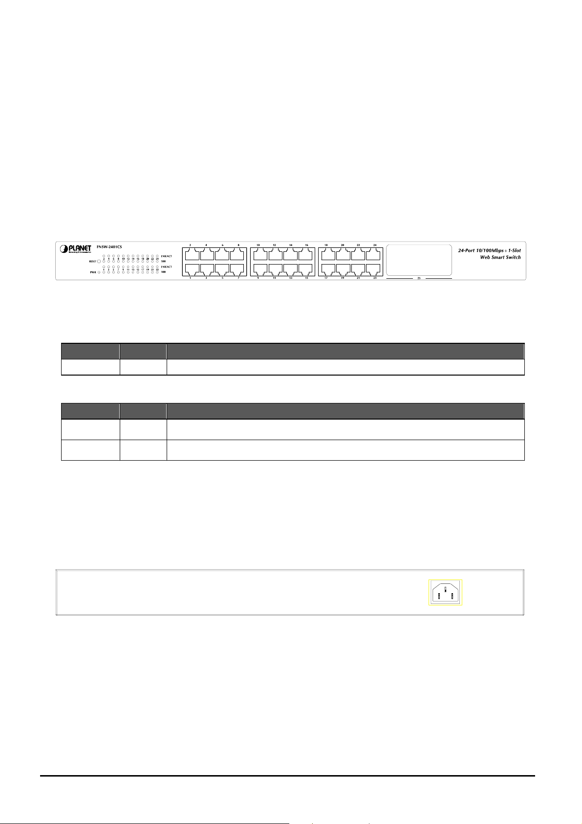
2.1 Front Panel
The Front Panel of the FNSW-2401CS Web Smart Fast Ethernet Switch consists of 24x Auto-Sensing 10/100Mbps
Ethernet RJ-45 Ports and one 100Base-FX fiber module slot; the LED Indicators are also located on the front panel of the
FNSW-2401CS.
Figure 2-1: FNSW-2401CS Switch front panel
2.1.1 LED indicators
System
LED Color Function
PWR Green Lights to indicate that the Switch has power.
Per 10/100Mbps port
LED Color Function
LNK/ACT Green Lights to indicate the link through that port is successfully established.
100 Orange Lights to indicate the port is running in 100Mbps speed.
#Notice:
Press the RESET button for 5 seconds. The FNSW-2401CS will back to the factory default mode; the entire configuration
will be erased.
2.2 Rear Panel
The rear panel of the FNSW-2401CS indicates an AC inlet power socket, which accepts input power from 100 to 240V AC,
50-60Hz.
100-240V AC
50/60Hz
Figure 2-2: FNSW-2401CS Switch rear panel
Power Notice:
1. The device is a power-required device, it means, it will not work till it is powered. If your networks should active all the
time, please consider using UPS (Uninterrupted Power Supply) for your device. It will prevent y ou from network data loss
or network downtime.
2. In some area, installing a surge suppression device may also help to protect y our FNSW-2401CS from being damaged
by unregulated surge or current to the FNSW-2401CS.
- 6 -
Page 7
2.3 Hardware Installation
This part describes how to install your Web Smart Ethernet Switch and make connections to the Switch. Please read
the following topics and perform the procedures in the order being presented. To install your Switch on a desktop or
shelf, simply completed the following steps.
2.3.1 Desktop Installation
To install a Switch on a desktop or shelf, simply completed the following steps:
Step 1: Attached the rubber feet to the recessed areas on the bottom of the Switch.
Step 2: Place the Switch on a desktop or shelf near an AC power source.
Step 3: Keep enough ventilation space between the Switch and the surrounding objects.
#Notice:
When choosing a location, please keep in mind the environmental restrictions discussed in Chapter 1, Section 4,
Specification.
Step 4: Connect your Switch to network devices.
A. Connect one end of a standard network cable to the 10/100 RJ-45 ports on the front of the FNSW-2401CS
Switch.
B. Connect the other end of the cable to the network devices such as printer servers, workstations or routers…etc.
#Notice:
Connection to the Switch requires UTP Category 5 network cabling with RJ-45 tips. For more information, please see
the Cabling Specification in Appendix A.
Step 5: Supply power to the Switch.
A. Connect one end of the power cable to the Switch.
B. Connect the power plug of the power cable to a standard wall outlet then power on the Switch.
When the Switch receives power, the Power LED should remain solid Green.
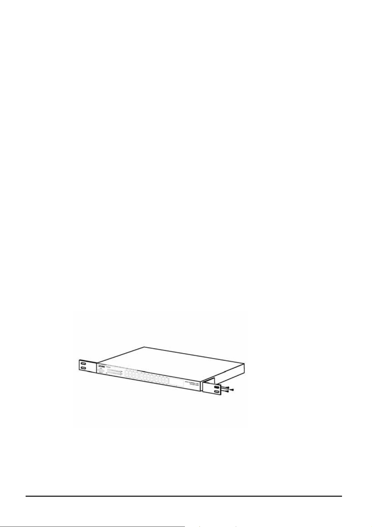
2.3.2 Rack Mounting
To install the Switch in a 19-inch standard rack, follow the instructions described below.
Step 1: Place your Switch on a hard flat surface, with the front panel positioned towards your front side.
Step 2: Attach a rack-mount bracket to each side of the Switch with supplied screws attached to the package. Figure
2-3 shows how to attach brackets to one side of the Switch.
Figure 2-3 Attaching the brackets to the Switch
- 7 -
Page 8
Caution:
You must use the screws supplied with the mounting brackets. Damage caused to the parts by using incorrect screw s would
invalidate your warranty.
Step 3: Secure the brackets tightly.
Step 4: Follow the same steps to attach the second bracket to the opposite side.
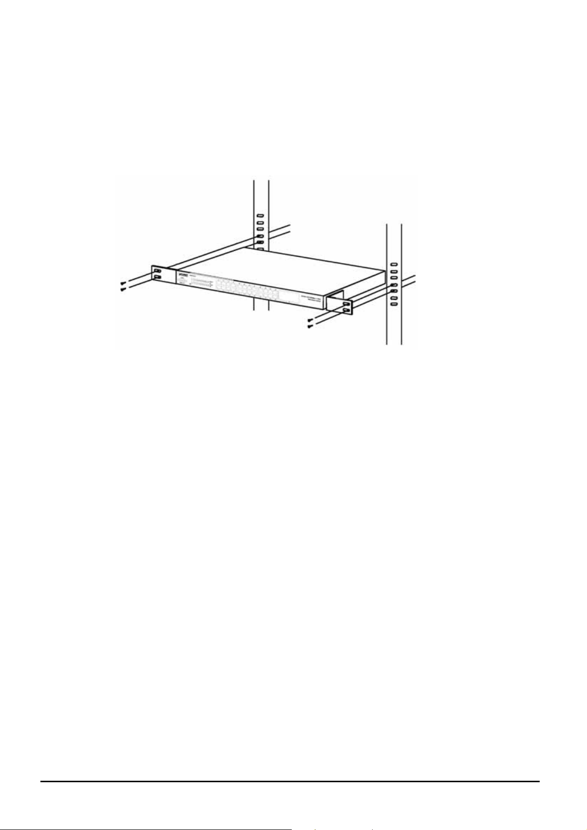
Step 5: After the brackets are attached to the Switch, use suitable screws to securely attach the brackets to the rack, as
shown in Figure 2-4.
Figure 2-4 Mounting the Switch in a Rack
Step 6: Proceed with the steps 4 and steps 5 of section 2.3.1 Desktop Installation to connect the network cabling and
supply power to your Switch.
- 8 -
Page 9

3. SWITCH MANAGEMENT
This chapter describes how to manage the FNSW-2401CS. Topics include:
- Overview
- Management method
- Logging on to the FNSW-2401CS
3.1 Overview
The FNSW-2401CS provides a user-friendly, web interface. Using this interface, you can perform various switch configuration and management activities, including:
Please refer to the following Chapter 4 for the details.
3.2 Management Method
User can manage the FNSW-2401CS by Web Management via a network or dial-up connection.
3.2.1 Web Management
You can manage the FNSW-2401CS remotely by having a remote host with web browser, such as Microsoft Internet Explorer or Netscape Navigator.
Using this management method:
The FNSW-2401CS must have an Internet Protocol (IP) address accessible for the remote host.
3.3 Logging on to the FNSW-2401CS
When you log on to the FNSW-2401CS Web interface for the first time, a sign-on string appears and you are prompted for
a Web login username and password.
The factory default login username is admin without password.
#Notice:
1. For security reason, please change and memorize the new password after this first setup.
2.
Only accept command in lowercase letter under Web interface.
- 9 -
Page 10

4. WEB MANAGEMENT
To modify your PC’s IP domain to the same with FNSW-2401CS then use the default IP address (192.168.0.100) to remote
configure FNSW-2401CS through the Web interface.
4.1 Login in to the Switch
To access the Web-browser interface you must first enter the user name, the default user name is "admin" without
password. You will see the following screen comes out on the Web browser program:
Figure 4-1 The FNSW-2401CS login Web Page screen
After the User name and Password is entered, you will see the web main menu screen.
- 10 -
Page 11
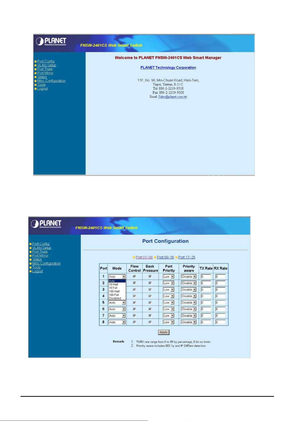
Figure 4-2 The web main menu screen of FNSW-2401CS
4-2 Port Config
This section provides each port configuration of FNSW-2401CS, the screen in Figure 4-3 appears and Table 4-1 describes
the port configuration object of switch.
Figure 4-3 FNSW-2401CS Port configuration Web Page screen
- 11 -
Page 12
Object Description
Port
Mode
Flow control
Back pressure
Port priority
Priority aware
TX Rate
RX Rate
Indicate port 1 to port 25.
Allow set each port run at Auto-negotiation mode or force 10/100Mbps half / full
duplex mode, also disable each port of FNSW-2401CS.
Allow to disable or enable Full-duplex flow control on each port.
Allow to disable or enable Half-duplex back pressure on each port.
Allow assign low queue or high queue on each port.
Allow to disable or enable priority aware function on each port.
Allow assign per port transmit bandwidth, the available range is 0-99
age; 0 for no limits.
Allow assign per port transmit bandwidth, the available range is 0-99
age; 0 for no limits.
Table 4-1 Descriptions of the Port Configuration screen Objects
by percent-
by percent-
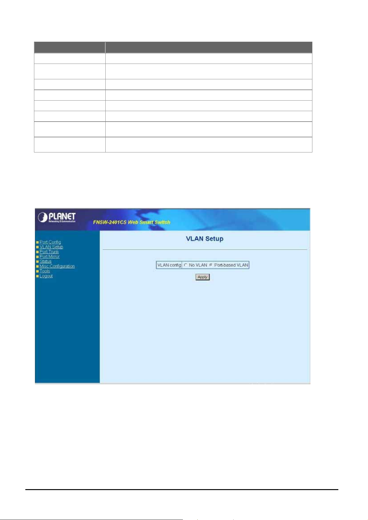
4-3 VLAN Setup
A Virtual LAN (VLAN) is a logical network grouping that limits the broadcast domain. It allows you to isolate network traffic
so only members of the VLAN receive traffic from the same VLAN members. The FNSW-2401CS supports 24 port-based
VLAN function. In the default configuration with VLAN disable, the screen in Figure 4-4 appears.
Figure 4-4 FNSW-2401CS VLAN Setup Web Page screen
Select “Port-based VLAN” and press “Apply” button, to enable the port-based VLAN function then continue configure
twenty-four port-based VLAN groups as your request. After setup completed, please press “Apply” to take affect and press
“Group 09~16” or “Group 17-24” hyperlink for other port-based VLAN groups. The screen in Figure 4-5 appears.
- 12 -
Page 13

Figure 4-5 FNSW-2401CS port-based VLAN Setting Web Page screen
4.3.1 VLAN setting example:
VLAN scenario
1. Port 24 is the file server port for all the workstations
2. Port 1 to port 23 is different devices that do need to see each other
Setup steps
1. Port Setting
1.1 Assign VLAN 1 for the second VLAN group with port 1 and port 24
1.2 Assign VLAN 2 for the second VLAN group with port 2 and port 24
1.3 Repeat the same steps for port 3 to port 23. i.e. 3 & 24, 4 & 24, ….., 23 & 24
After the above steps port 1 to port 23 is being separated physically due to it belongs to dif ferent VLAN group s
(different VLAN). However , they all can access port 24 due to port 24 is overlapping port to communicate with
port 1 to port 23.
- 13 -
Page 14

4-4 Port Trunk Setup
This section allows you to disable or enable trunk function of two ports or four ports together to speed up data transmission.
The screen in Figure 4-6 appears.
Figure 4-6 FNSW-2401CS Port Trunk Setup Web Page screen
#Notice:
After turn on the port trunk feature, port 1 and port 2, port 1,2,3,4 or port 5,6,7,8 should connect to another
switch, such as another FNSW-2401CS, that also supports port trunk feature to double the bandwidth in
between. Otherwise, if the connected switch do not support port trunk, it will cause network loop and hangs the
whole network.
- 14 -
Page 15

4-5 Port Mirror Setup
This section allow to configure port mirror function of FNSW-2401CS, the screen in Figure 4-7 appears and table 4-2 descriptions the port mirror objects of FNSW-2401CS.
Figure 4-7 FNSW-2401CS Port Mirror Configuration Web Page screen
Object Description
Port Mirroring
Monitoring port
Monitored port
Monitoring mode
Table 4-2 Descriptions of the port mirror configuration screen Objects
Allow disable or enable port mirroring function.
Allow assign one port as Monitoring port.
Allow assign one port as Monitored port.
Allow choosing Monitoring mode and the available options are TX, RX, Both TX RX.
- 15 -
Page 16

4-6 Status
This section allows viewing System information and port status of FNSW-2401CS, the screen in Figure 4-8 appears and
please refer to “chapter 4.6.1 System Info” and “chapter 4.6.2 Port Status” for detail information.
Figure 4-8 FNSW-2401CS Status Web Page screen
- 16 -
Page 17

4.6.1 System Information
This section provides System information of FNSW-2401CS, the screen in Figure 4-9 appears and table 4-3 descriptions
the System information objects of FNSW-2401CS.
Figure 4-9 FNSW-2401CS System Information Web Page screen
Object Description
Mac address
SW Version
IP Address
Subnet Mask
Default Gateway
Table 4-3 Descriptions of System information screen Objects
Display MAC address of FNSW-2401CS.
Display firmware version of FNSW-2401CS.
Display IP address of FNSW-2401CS.
Display subnet Mask of FNSW-2401CS.
Display Gateway of FNSW-2401CS.
- 17 -
Page 18

4.6.2 Port Status
This section provides to view per port status of FNSW-2401CS, the screen in Figure 4-10 appears and table 4-4 descriptions the port status objects of FNSW-2401CS.
Figure 4-10 FNSW-2401CS Port Status Web Page screen
Object Description
Port No.
Flow control
Duplex
Speed
Link
Table 4-4 Descriptions of Port Status screen Objects
Indicate port 1 to port 25.
Display the flow control On or Off state on each port of FNSW-2401CS.
Display half or full duplex mode on each port of FNSW-2401CS.
Display the 10Mbps or 100Mbps speed state of each port on FNSW-2401CS.
The state of the link, indicating a valid link partner device. "Up" means a device is
successful connected to the port. “Down” means no device is connected.
- 18 -
Page 19

A
4-7 Misc Configuration
This section provides Misc Configuration of FNSW-2401CS, the screen in Figure 4-11 appears and table 4-5 descriptions
the Misc Configuration objects of FNSW-2401CS.
Figure 4-11 FNSW-2401CS Misc Configuration Web Page screen
Object Description
IP Address
Password
Switch Control
Table 4-5 Descriptions of Misc Configuration screen Objects
Allow user to assign IP address, Subnet Mask, Gateway of FNSW-2401CS, please refer to
chapter 4.7.1
Allow user to change the password and maximum up to 8 characters, please refer to chapter
4.7.2
llow user to configuring Broadcast Storm Control, Address Table Aging, Aging Time, Class of
Service Mode function of FNSW-2401CS refer to chapter 4.7.3
- 19 -
Page 20

4.7.1 IP Address
This section allow user to assign IP subnet address of FNSW-2401CS, the screen in Figure 4-12 appears and table 4-6
descriptions the IP Address objects of FNSW-2401CS.
Figure 4-12 FNSW-2401CS IP Address Web Page screen
Object Description
IP address
Subnet Mask
Default Gateway
Table 4-6 Descriptions of IP Address screen Objects
Assign IP address of FNSW-2401CS.
Assign subnet Mask of FNSW-2401CS.
Assign Gateway of FNSW-2401CS.
- 20 -
Page 21

4.7.2 Password
This section allow user to modify password of FNSW-2401CS, the screen in Figure 4-13 appears and table 4-7 descriptions
the password setting objects of FNSW-2401CS.
Figure 4-13 FNSW-2401CS Password Setting Web Page screen
Object Description
Username
Password
New password
Table 4-7 Descriptions of Password setting screen Objects
Indicate the username of FNSW-2401CS and its read only.
Input previous password of FNSW-2401CS.
Input new password of FNSW-2401CS.
#Notice:
1. For security reason, please change and memorize the new password after this setup.
2.
The maximum length is 8 characters.
- 21 -
Page 22

4.7.3 Switch Control
This section allow user to setup Broadcast Storm Control, Address Table Aging, Aging Time, Class of Services function of
FNSW-2401CS. The screen in Figure 4-14 appears and tables 4-8 descriptions the Switch Control setting objects of
FNSW-2401CS.
Figure 4-14 FNSW-2401CS Switch Control Web Page screen
Object Description
Broadcast Control
Address Table Aging
Aging time
Class of Services
WRR Ratio (High : Low)
Table 4-8 Descriptions of the Switch Control Configuration screen Objects
Allow disable or enable broadcast storm control with 20%, 50%, and 80% for pass.
Allow disable or enable Mac address table aging.
Allow to input the aging time and available range is 30 to 600 seconds (must be
multiple of 30).
Allow to choose different policy for Class of Service.
Available when choose Weighted Round Robin as Class of Service schedule.
- 22 -
Page 23

A
4-8 Tools
This section provides tools of FNSW-2401CS; the screen in Figure 4-15 appears and table 4-9 descriptions the tools
Configuration objects of FNSW-2401CS.
Figure 4-15 FNSW-2401CS Tools Configuration Web Page screen
Object Description
Reboot
Factory Reset
Firmware upgrade
Table 4-9 Descriptions of Tools Configuration screen Objects
Allow user to reboot the FNSW-2401CS, please refer to chapter 4.8.1.
Allow user to reset FNSW-2401CS to factory default mode, please refer to chapter 4.8.2.
llow user proceed firmware update procedure of FNSW-2401CS, please refer to chapter 4.8.3.
- 23 -
Page 24

4.8.1 Reboot
This section allow user to reboot the FNSW-2401CS, the screen in Figure 4-16 & 4-17 & 4-18 appears.
Figure 4-16 FNSW-2401CS Reboot Web Page screen
Figure 4-17 FNSW-2401CS Reboot Web Page screen
- 24 -
Page 25

Figure 4-18 FNSW-2401CS Reboot Web Page screen
4.8.2 Factory Reset
This section allow user to reset the FNSW-2401CS to factory default mode, the screen in Figure 4-19 & 4-20 & 4-21 ap-
pears.
Figure 4-19 FNSW-2401CS Factory Reset Web Page screen
- 25 -
Page 26

Figure 4-20 FNSW-2401CS Factory Reset Web Page screen
Figure 4-21 The FNSW-2401CS login Web Page screen
- 26 -
Page 27

4.8.3 Firmware Upgrade
This section provides firmware upgrade of FNSW-2401CS, after choose this function and the following screen appears in
Figure 4-22. Please press “Update” button to continue following firmware upgrade process.
Figure 4-22 The FNSW-2401CS firmware upgrade Web Page screen
Please wait for two seconds and press “Continue” to next firmw are upgrade web page, the screen in Figure 4-23 & Figure
4-24 appears.
Figure 4-23 The FNSW-2401CS firmware upgrade Web Page screen
- 27 -
Page 28

Figure 4-24 The FNSW-2401CS firmware upgrade Web Page screen
Please press “Browser” to locate the latest firmware of FNSW-2401CS that deposit in your PC and press
“Upgrade” to start the firmware upgrade process. The screen in Figure 4-25 appears.
Figure 4-25 The FNSW-2401CS firmware upgrade Web Page screen
- 28 -
Page 29

Please wait for seventeen seconds and go to next firmware upgrade web page, the screen in Figure 4-26 appears.
Figure 4-26 The FNSW-2401CS firmware upgrade Web Page screen
Then the re-login screen appears in Figure 4-27, please press “Re Login” button to re-login web interface of
FNSW-2401CS with latest firmware version, the screen in Figure 4-28 appears.
Figure 4-27 The FNSW-2401CS firmware upgrade Web Page screen
- 29 -
Page 30

Figure 4-28 The FNSW-2401CS login Web Page screen
#Notice: Please does not power off the FNSW-2401CS during firmware upgrade process.
- 30 -
Page 31

4-9 Logout
This section allows to logout the FNSW-2401CS, the screen in Figure 4-29 & 4-30 & 4-31 appears.
Figure 4-29 FNSW-2401CS Logout Web Page screen
Figure 4-30 The FNSW-2401CS Logout Web Page screen
- 31 -
Page 32

Figure 4-31 The FNSW-2401CS login Web Page screen
- 32 -
Page 33

5. SWITCH OPERATION
5.1 Address Table
The Switch is implemented with an address table. This address table composed of many entries. Each entry is used to
store the address information of some node in network, including MAC address, port no, etc. This information comes
from the learning process of Ethernet Switch.
5.2 Learning
When one packet comes in from any port. The Switch will record the source address, port no. And the other related
information in address table. This information will be used to decide either forwarding or filtering for future packets.
5.3 Forwarding & Filtering
When one packet comes from some port of the Ethernet Switching, it will also check the destination address besides
the source address learning. The Ethernet Switching will lookup the address-table for the destination address. If not
found, this packet will be forwarded to all the other ports except the port which this packet comes in. And these ports
will transmit this packet to the network it connected. If found, and the destination address is located at different port
from this packet comes in, the Ethernet Switching will forward this packet to the port where this destination address is
located according to the information from address table. But, if the destination address is located at the same port with
this packet comes in, then this packet will be filtered. Thereby increasing the network throughput and availability.
5.4 Store-and-Forward
Store-and-Forward is one type of packet-forwarding techniques. A Store-and Forward Ethernet Switching stores the
incoming frame in an internal buffer, do the complete error checking before transmission. Therefore, no error packets
occurrence, it is the best choice when a network needs efficiency and stability.
The Ethernet Switch scans the destination address from the packet-header, searches the routing table provided for
the incoming port and forwards the packet, only if required. The fast forwarding makes the switch attractive for connecting servers directly to the network, thereby increasing throughput and availability. However, the switch is most
commonly used to segment existing hubs, which nearly always improves overall performance. An Ethernet Switching
can be easily configured in any Ethernet network environment to significantly boost bandwidth using conventional
cabling and adapters.
Due to the learning function of the Ethernet switching, the source address and corresponding port number of each
incoming and outgoing packet are stored in a routing table. This information is subsequently used to filter packets
whose destination address is on the same segment as the source address. This confines network traffic to its respective domain, reducing the overall load on the network.
The Switch performs "Store and forward" therefore, no error packets occur. More reliably, it reduces the
re-transmission rate. No packet loss will occur.
5.5 Auto-Negotiation
The STP ports on the FNSW-2401CS switch have built-in "Auto-negotiation". This technology automatically sets the
best possible bandwidth when a connection is established with another network device (usually at Power On or Reset).
Detecting the modes does this and speeds at the second of both devices are connected and capable of, both
10Base-T and 100Base-TX devices can connect with the port in either Half- or Full-duplex mode.
- 33 -
Page 34

6.TROUBLESHOOTING
This chapter contains information to help you solve problems. If the Switch is not functioning properly, make sure the
Ethernet Switch was set up according to instructions in this manual.
The Link LED is not lit
Solution:
Check the cable connection and remove duplex mode of the Switch.
Some stations cannot talk to other stations located on the other port
Solution:
Please check the VLAN, port trunking function that may introduce this kind of problem.
Performance is bad
Solution:
Check the full duplex status of the Ethernet Switch. If the Ethernet Switch is set to full duplex and the partner is set to
half duplex, then the performance will be poor.
100Base-TX port link LED is lit, but the traffic is irregular
Solution:
Check that the attached device is not set to dedicate full duplex. Some devices use a physical or software switch to
change duplex modes. Auto-negotiation may not recognize this type of full-duplex setting.
Why the Switch doesn’t connect to the network
Solution:
Check the LNK/ACT LED on the switch Try another port on the Switch Make sure the cable is installed properly Make
sure the cable is the right type Turn off the power. After a while, turn on power again.
How to deal forgotten password situation of FNSW-2401CS?
Solution:
Please press “RESET” button from front panel of FNSW-2401CS for 5 seconds then the
FNSW-2401CS will reset to factory default mode( username: admin without password.)
- 34 -
Page 35

APPENDIX A NETWORKING CONNECTION
A.1 Switch‘s RJ-45 Pin Assignments
Contact MDI MDI-X
1 1 (TX +) 3
2 2 (TX -) 6
3 3 (RX +) 1
6 6 (RX -) 2
4, 5, 7, 8 Not used Not used
A.2 RJ-45 cable pin assignment
2 1
3 6
2 1 3 6
6
3
2
1
There are 8 wires on a standard UTP/STP cable and each wire is color-coded. The following shows the pin allocation and
color of straight cable and crossover cable connection:
Figure A-1: Straight-Through and Crossover Cable
Please make sure your connected cables are with same pin assignment and color as above picture before deploying the
cables into your network.
- 35 -
Page 36

- 36 -
Page 37

- 37 -
Page 38

2010-A81110-001
- 38 -
 Loading...