

Page 1

FNSW-2400PS
User's Manual
24-Port 10/100Mbps
POE Web Smart Ethernet Switch
- 1 -
Page 2

Trademarks
Copyright © PLANET Technology Corp. 2011.
Contents subject to revision without prior notice.
PLANET is a registered trademark of PLANET Technology Corp. All other trademarks belong to their respective
owners.
Disclaimer
PLANET Technology does not warrant that the hardware will work properly in all environments and applications,
and makes no warranty and representation, either implied or expressed, with respect to the quality, performance,
merchantability, or fitness for a particular purpose.
PLANET has made every effort to ensure that this User’s Manual is accurate; PLANET disclaims liability for any
inaccuracies or omissions that may have occurred.
Information in this User’s Manual is subject to change without notice and does not represent a commitment on the
part of PLANET. PLANET assumes no responsibility for any inaccuracies that may be contained in this User’s
Manual. PLANET makes no commitment to update or keep current the information in this User’s Manual, and
reserves the right to make improvements to this User’s Manual and/or to the products described in this User’s
Manual, at any time without notice.
If you find information in this manual that is incorrect, misleading, or incomplete, we would appreciate your
comments and suggestions.
User’s Manual of FNSW-2400PS
FCC Warning
This equipment has been tested and found to comply with the limits for a Class A digital device, pursuant to Part
15 of the FCC Rules. These limits are designed to provide reasonable protection against harmful interference
when the equipment is operated in a commercial environment. This equipment generates, uses, and can radiate
radio frequency energy and, if not installed and used in accordance with the Instruction manual, may cause
harmful interference to radio communications. Operation of this equipment in a residential area is likely to cause
harmful interference in which case the user will be required to correct the interference at his own expense.
CE Mark Warning
This is a Class A product. In a domestic environment, this product may cause radio interference, in which case
the user may be required to take adequate measures.
Energy Saving Note of the Device
This power required device does not support Standby mode operation.
For energy saving, please remove the power cable to disconnect the device from the power circuit.
Without removing power cable, the device will still consuming power from the power source. In the view of Saving
the Energy and reduce the unnecessary power consuming, it is strongly suggested to remove the power con-
nection for the device if this device is not intended to be active.
WEEE Warning
To avoid the potential effects on the environment and human health as a result of the presence of
hazardous substances in electrical and electronic equipment, end users of electrical and electronic
equipment should understand the meaning of the crossed-out wheeled bin symbol. Do not dispose of
WEEE as unsorted municipal waste and have to collect such WEEE separately.
Revision
PLANET 24-Port 10/100Mbps POE Web Smart Ethernet Switch User's Manual
FOR MODEL: FNSW-2400PS
REVISION: 1.1(OCTOBER.2011)
Part No.: 2081-A81180-001
- 2 -
Page 3

User’s Manual of FNSW-2400PS
TABLE OF CONTENTS
1. INTRODUCTION ...............................................................................6
1.1 CHECKLIST ................................................................................................................................................ 6
1.2 ABOUT THE SWITCH ................................................................................................................................... 6
1.3 FEATURES ................................................................................................................................................. 7
1.4 SPECIFICATION .......................................................................................................................................... 8
2. HARDWARE DESCRIPTION ............................................................10
2.1 FRONT PANEL .......................................................................................................................................... 10
2.1.1 LED Indicators................................................................................................................................. 10
2.2 REAR PANEL............................................................................................................................................ 10
2.3 HARDWARE INSTALLATION ........................................................................................................................ 11
2.3.1 Desktop Installation......................................................................................................................... 11
2.3.2 Rack Mounting ................................................................................................................................12
3. SWITCH MANAGEMENT .................................................................14
3.1 OVERVIEW ............................................................................................................................................... 14
3.2 MANAGEMENT METHOD............................................................................................................................ 14
3.2.1 Web Management........................................................................................................................... 14
3.3 LOGGING ON TO THE FNSW-2400PS ....................................................................................................... 15
4. WEB MANAGEMENT........................................................................16
4.1 LOGIN IN TO THE SWITCH.......................................................................................................................... 16
4.2 ADMINISTRATOR....................................................................................................................................... 17
4.2.1 System Information ......................................................................................................................... 18
4.2.2 IP Configuration ..............................................................................................................................19
4.2.3 Password Setting ............................................................................................................................ 20
4.2.4 Factory Default................................................................................................................................20
4.2.5 Firmware Update ............................................................................................................................ 21
4.2.6 Reboot............................................................................................................................................. 22
4.3 PORT MANAGEMENT ................................................................................................................................23
4.3.1 Port Configuration ........................................................................................................................... 24
4.3.2 Port Mirroring .................................................................................................................................. 25
4.3.3 Bandwidth Control........................................................................................................................... 26
4.3.4 Broadcast Storm Control................................................................................................................. 27
4.3.5 Port Statistics .................................................................................................................................. 27
4.4 VLAN SETTING ........................................................................................................................................ 29
4.4.1 VLAN Mode..................................................................................................................................... 32
4.4.1.1 Port Base VLAN Mode................................................................................................................. 33
4.4.1.2 Tag Base VLAN Mode ................................................................................................................. 33
4.4.2 VLAN Member................................................................................................................................. 34
4.4.3 Multi to 1 Setting .............................................................................................................................36
- 3 -
Page 4

User’s Manual of FNSW-2400PS
4.5 QOS SETTING.......................................................................................................................................... 37
4.5.1 Priority Mode................................................................................................................................... 37
4.5.2 Class of Service .............................................................................................................................. 38
4.6 SECURITY ................................................................................................................................................ 41
4.6.1 MAC Address Binding..................................................................................................................... 42
4.6.2 TCP / UDP Scan ............................................................................................................................. 43
4.6.3 TCP / UDP Filter .............................................................................................................................43
4.6.4 IP Address Filter ............................................................................................................................. 45
4.7 SPANNING TREE....................................................................................................................................... 46
4.7.1 STP Bridge Settings........................................................................................................................ 47
4.7.2 STP Port Settings ........................................................................................................................... 48
4.7.3 Loopback Detection Settings .......................................................................................................... 50
4.8 TRUNKING................................................................................................................................................ 51
4.9 DHCP RELAY AGENT ............................................................................................................................... 53
4.9.1 DHCP Relay Agent ......................................................................................................................... 54
4.9.2 Relay Server ................................................................................................................................... 55
4.9.3 VLAN MAP Relay Agent ................................................................................................................. 55
4.10 BACKUP/RECOVERY ............................................................................................................................... 56
4.11 MISCELLANEOUS .................................................................................................................................... 57
4.11.1 Miscellaneous Settings ................................................................................................................. 57
4.11.2 IGMP Static Router Settings ......................................................................................................... 58
4.12 SNMP SETTINGS ................................................................................................................................... 59
4.13 SAVE SETTINGS .....................................................................................................................................60
4.14 LOGOUT ................................................................................................................................................ 60
5. SWITCH OPERATION......................................................................61
5.1 ADDRESS TABLE ...................................................................................................................................... 61
5.2 LEARNING ................................................................................................................................................ 61
5.3 FORWARDING & FILTERING ....................................................................................................................... 61
5.4 STORE-AND-FORWARD............................................................................................................................. 61
5.5 AUTO-NEGOTIATION ................................................................................................................................. 62
6. POWER OVER ETHERNET OVERVIEW..............................................63
7. THE POE PROVISION PROCESS ......................................................65
7.1 LINE DETECTION ...................................................................................................................................... 65
7.2 CLASSIFICATION....................................................................................................................................... 65
7.3 START-UP ................................................................................................................................................ 66
7.4 OPERATION.............................................................................................................................................. 66
7.5 POWER DISCONNECTION SCENARIOS ........................................................................................................ 66
- 4 -
Page 5

User’s Manual of FNSW-2400PS
8. TROUBLESHOOTING.......................................................................67
APPENDIX A NETWORKING CONNECTION..........................................68
A.1 SWITCH‘S RJ-45 PIN ASSIGNMENTS ......................................................................................................... 68
A.2 RJ-45 CABLE PIN ASSIGNMENT ................................................................................................................. 68
A.3 DATA OUT POE INJECTOR RJ-45 PORT PIN ASSIGNMENTS ..................................................................... 69
- 5 -
Page 6

User’s Manual of FNSW-2400PS
1. INTRODUCTION
1.1 Checklist
Check the contents of your package for following parts:
z FNSW-2400PS x1
z Quick Installation Guide x1
z User's Manual CD x1
z Power Cord x 1
z Rubber Feet x 4
z Two Rack-mounting Brackets with Attachment Screws x1
If any of these pieces are missing or damaged, please contact your dealer immediately, if possible, retain the carton
including the original packing material, and use them against to repack the product in case there is a need to return it to
us for repair.
In the following section, the term “POE Web Smart Ethernet Switch” means the Switch device, ie. FNSW-2400PS;
term of “switch” can be any third switches.
1.2 About the Switch
The FNSW-2400PS provides 24 10/100Mbps POE Fast Ethernet ports, the Web Smart PoE Switch supports MDI / MDI-X
convertible on 24 10/100Mbps ports and also provides PoE inject function on port#1 to port#24 which is able to drive at
least 8 IEEE 802.3af 15.4Watts compliant powered devices.
The unshielded twisted-pair (UTP) cable ports providing dedicated 10/100Mbps bandwidth, the dual speed ports used
standard twisted-pair cabling and are ideal for SOHO or segmenting networks into small. Each 10/100Mbps port can
supports up to 200Mbps of throughput in full-duplex mode, the POE Web Smart Ethernet Switch also provides a simple,
cost-effective, and highly reliable network connection for data as well as power. Furthermore, it is the ideal device for
bridging among Ethernet, Fast Ethernet workgroups and networks.
The FNSW-2400PS equipped with non-blocking 4.8Gbps backplane, greatly simplifies the tasks of upgrading your LAN for
catering to increase bandwidth demands.
For efficient management, the FNSW-2400PS is equipped with remote Web interface. The Web Smart PoE Switch can be
programmed for advanced switch management functions such as SNMP , port configuration, port-based / IEEE 802.1Q /
MTU VLAN, port mirroring, port trunk, QoS, bandwidth control, broadcast storm control, MAC address / TCP & UDP filter
and IGMP Snooping v1/v2.
- 6 -
Page 7

User’s Manual of FNSW-2400PS
1.3 Features
¾ Physical Port
24-Port 10/100Mbps Fast Ethernet ports with PoE Injector
Reset button for system management
¾ PoE
Complies with IEEE 802.3af Power over Ethernet Mid-Span PSE
Up to 24 IEEE 802.3af devices powered
Supports PoE Power up to 15.4 Watts for each 802.3af PoE port
Auto detect powered device (PD)
Circuit protection prevents power interference between ports
Remote power feeding up to 100m
¾ Layer 2 Features
Auto-MDI/MDI-X detection on each RJ-45 port
Prevents packet loss with back pressure (Half-Duplex) and IEEE 802.3x PAUSE Frame Flow control
(Full-Duplex)
Support VLAN:
- IEEE 802.1Q Tag-based VLAN
- Port-Based VLAN
- MTU VLAN (Multi-Tenant Unit VLAN)
Support Link Aggregation
− up to 2 trunk groups
− up to 4 Fast Ethernet ports per trunk group
− IEEE 802.3ad LACP (Link Aggregation Control Protocol)
Support Spanning Tree Protocol
- STP, IEEE 802.1D (Classic Spanning Tree Protocol)
- RSTP, IEEE 802.1w (Rapid Spanning Tree Protocol)
- Loopback Detection
Port Mirroring to monitor the incoming or outgoing traffic on a particular port
¾ Quality of Service
2 priority queues on all switch ports
Traffic classification:
- Port-Based priority
- IEEE 802.1p-Based priority
- IP TOS / DSCP-Based priority
- TCP / UDP Port Based QoS
Strict priority and Weighted Round Robin (WRR) CoS policies
In/Out rate limit control on each port
Broadcast Storm Control support
¾ Multicast
Supports IGMP Snooping v1 and v2
¾ Security
MAC address filter
TCP & UDP filter on each port
- 7 -
Page 8

Management idle time security
¾ Management
Remote Web interface for Switch management and setup
Supports SNMP v1
Supports DHCP Option82 and DHCP Relay
Firmware upgrade through Web interface
Configuration upload / download through Web interface
Reset button for system reboot or reset to factory default
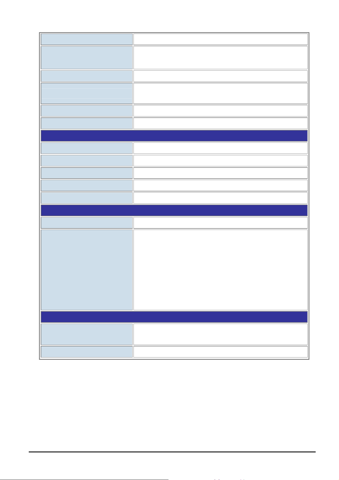
1.4 Specification
User’s Manual of FNSW-2400PS
Model
Hardware Specification
Ports
Switch Processing Scheme
Throughput (packet per second)
Switch Fabric
Address Table
Share Data Buffer
Flow Control
Dimensions (W x D x H)
Weight
Power Requirement
Power Consumption / Dissipation Max.135 Watts / 460 BTU
Smart Function
FNSW-2400PS
24 10/100Base-TX RJ-45 Auto-MDI/MDI-X interfaces
Store-and-Forward
3.57Mpps@64Bytes
4.8Gbps
8K entries
1.75Mb embedded memory for packet buffers
Back pressure for Half Duplex, IEEE 802.3x Pause Frame for Full Duplex
445 x 207 x 45 mm (1U height)
2.55kg
100~240V AC, 50-60 Hz, 2A
System Configuration
Port Configuration
Bandwidth Control
Broadcast Storm Control
Port Statistics
VLAN
Spanning Tree Protocol
- 8 -
Web interface, SNMP v1
Port Speed Duplex mode selection
Port Disable / Enable
Yes
Yes / Threshold 1~63
Display each port’s detail Ethernet traffic counter information
24 Port-based VLAN groups
32 IEEE 802.1Q VLAN groups
MTU VLAN
STP, IEEE 802.1D (Spanning Tree Protocol)
Page 9
User’s Manual of FNSW-2400PS
RSTP, IEEE 802.1w (Rapid Spanning Tree Protocol)
Port Trunking
Port Mirroring
QoS
MAC Address / TCP & UDP Filter
IGMP Snooping v1 / v2
Power over Ethernet
PoE Standard
PoE Power Supply Type
PoE Power output
Power Pin Assignment
PoE Power Budget
Standards Conformance
Support 2 groups of 4-Port 10/ 100Base-TX trunk support
Up to 800Mbps bandwidth per trunk (Full-Duplex)
Port mirroring allows monitoring of the traffic across any port in real time
Allow to assign low / high priority on each port.
First-In-First-Out, All-High-before-Low, Weight-Round-Robin QoS policy.
Yes
Allow to Disable or Enable.
IEEE 802.3af Power over Ethernet / PSE
Mid-Span
Per Port 48V DC, 350mA . Max. 15.4 watts
4/5(-), 7/8(+)
125Watts
Regulation Compliance
Standards Compliance
Environment
Temperature
Humidity Operating
FCC Part 15 Class A, CE
IEEE 802.3 Ethernet
IEEE 802.3u Fast Ethernet
IEEE 802.3af Power over Ethernet (15.4Watts)
IEEE 802.3x Full-duplex flow control
IEEE 802.1Q VLAN
IEEE 802.1p QoS
IEEE 802.1D Spanning Tree Protocol
IEEE 802.1w Rapid Spanning Tree Protocol
Operating: 0~50 Degree C
Storage: -10~70 Degree
5% to 95%, Storage: 5% to 95% (Non-condensing)
- 9 -
Page 10
User’s Manual of FNSW-2400PS
2. HARDWARE DESCRIPTION
This product provides two different running speeds – 10Mbps and 100Mbps in the same POE Web Smart Ethernet Switch
and automatically distinguishes the speed of incoming connection.
This section describes the hardware features of FNSW-2400PS. For easier management and control of the
FNSW-2400PS, familiarize yourself with its display indicators, and ports. Front panel illustrations in this chapter display the
unit LED indicators. Before connecting any network device to the FNSW-2400PS, read this chapter carefully.
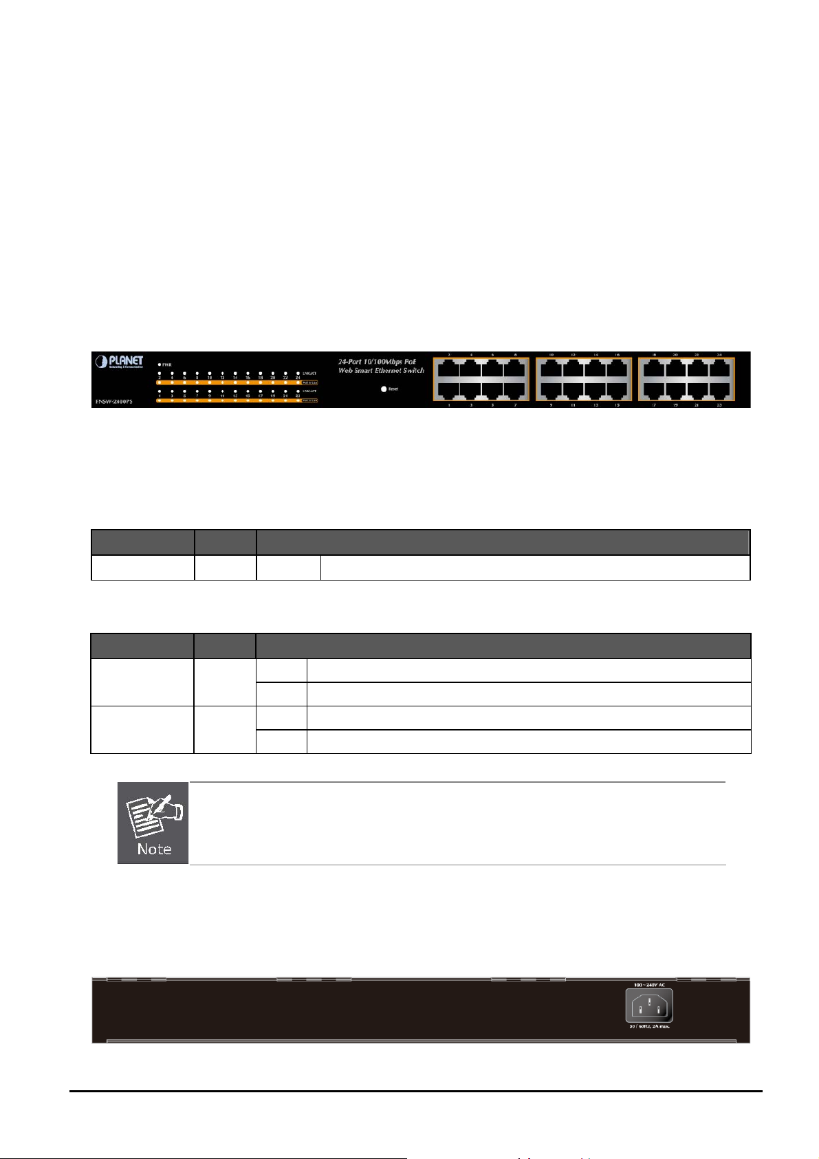
2.1 Front Panel
The Front Panel of the FNSW-2400PS consists of 24x Auto-Sensing 10/100Mbps Ethernet RJ-45 Ports
The LED Indicators are also located on the front panel of the POE Web Smart Ethernet Switch.
Figure 2-1: FNSW-2400PS Switch Front Panel
2.1.1 LED Indicators
System
LED Color Function
PWR Green Lights Indicate that the Switch has power.
Per 10/100Base-TX, PoE interfaces (Port-1 to Por-24)
LED Color Function
LNK/ACT
PoE In-Use
Green
Orange
1. Press the RESET button once. The POE Web Smart Ethernet Switch will reboot automatically.
Lights:
Blink:
Lights:
OFF:
2. Press the RESET button for 5 ~ 10 seconds. The POE Web Smart Ethernet Switch will back to
the factory default mode; the entire configuration will be erased.
Indicate the link through that port is successfully established.
Indicate the Switch is actively sending or receiving data over that port.
Indicate the port is providing 48VDC in-line power.
Indicate the connected device is not a PoE Powered Device (PD).
2.2 Rear Panel
The rear panel of the POE Web Smart Ethernet Switch indicates an AC inlet power socket, which accepts input power from
100 to 240VAC, 50-60Hz, 2A.
Figure 2-2: FNSW-2400PS Switch rear panel
- 10 -
Page 11

User’s Manual of FNSW-2400PS
Power Notice:
1. The device is a power-required device, it means, it will not work till it is powered. If your networks should active all the
time, please consider using UPS (Uninterrupted Power Supply) for your device. It will prevent you from network data
loss or network downtime.
2. In some area, installing a surge suppression device may also help to protect your POE Web Smart Ethernet Switch
from being damaged by unregulated surge or current to the POE Web Smart Ethernet Switch.
2.3 Hardware Installation
This part describes how to install your POE Web Smart Ethernet Switch and make connections to the Switch. Please read
the following topics and perform the procedures in the order being presented. To install your POE Web Smart Ethernet
Switch on a desktop or shelf, simply completed the following steps.
2.3.1 Desktop Installation
To install POE Web Smart Ethernet Switch on a desktop or shelf, simply completed the following steps:
Step 1: Attached the rubber feet to the recessed areas on the bottom of the POE Web Smart Ethernet Switch.
Step 2: Place the POE Web Smart Ethernet Switch on a desktop or shelf near an AC power source.
Step 3: Keep enough ventilation space between the POE Web Smart Ethernet Switch and the surrounding objects.
When choosing a location, please keep in mind the environmental restrictions discussed in Chapter
1, Section 4, Specification.
Step 4: Connect your Switch to network devices.
A. Connect one end of a standard network cable to the 10/100 RJ-45 ports on the front of the POE Web Smart Ethernet
Switch.
B. Connect the other end of the cable to the network devices such as printer servers, workstations or routers…etc.
Connection to the POE Web Smart Ethernet Switch requires UTP Category 5 or above cabling with
RJ-45 tips. For more information, please see the Cabling Specification in Appendix A.
Step 5: Supply power to the POE Web Smart Ethernet Switch.
A. Connect one end of the power cable to the POE Web Smart Ethernet Switch.
B. Connect the power plug of the power cable to a standard wall outlet then power on the POE Web Smart Ethernet
Switch.
When the POE Web Smart Ethernet Switch receives power, the Power LED should remain solid Green.
- 11 -
Page 12
User’s Manual of FNSW-2400PS
2.3.2 Rack Mounting
To install the POE Web Smart Ethernet Switch in a 19-inch standard rack, follow the instructions described below.
Step 1: Place your POE Web Smart Ethernet Switch on a hard flat surface, with the front panel positioned towards your
front side.
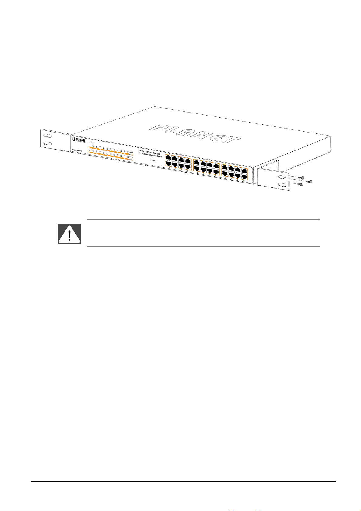
Step 2: Attach a rack-mount bracket to each side of the POE Web Smart Ethernet Switch with supplied screws attached to
the package. Figure 2-3 shows how to attach brackets to one side of the POE Web Smart Ethernet Switch.
Figure 2-3 Attaching the brackets to the POE Web Smart Ethernet Switch
You must use the screws supplied with the mounting brackets. Damage caused to the parts by
using incorrect screws would invalidate your warranty.
Step 3: Secure the brackets tightly.
Step 4: Follow the same steps to attach the second bracket to the opposite side.
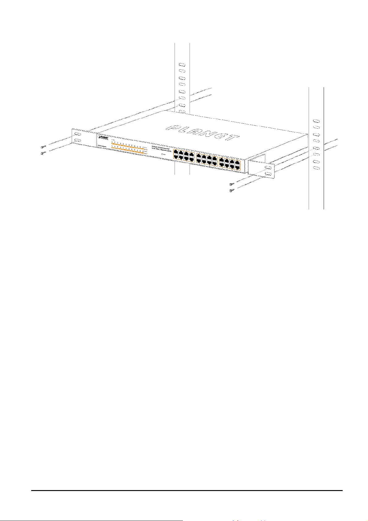
Step 5: After the brackets are attached to the POE Web Smart Ethernet Switch, use suitable screws to securely attach the
brackets to the rack, as shown in Figure 2-4.
- 12 -
Page 13
User’s Manual of FNSW-2400PS
Figure 2-4 Mounting the POE Web Smart Ethernet Switch in a Rack
Step 6: Precede with the steps 4 and steps 5 of section 2.3.1 Desktop Installation to connect the network cabling and
supply power to your POE Web Smart Ethernet Switch.
- 13 -
Page 14
User’s Manual of FNSW-2400PS
3. SWITCH MANAGEMENT
This chapter describes how to manage the POE Web Smart Ethernet Switch. Topics include:
- Overview
- Management method
- Logging on to the POE Web Smart Ethernet Switch
3.1 Overview
The POE Web Smart Ethernet Switch provides a user-friendly, Web interface. Using this interface, you can perform var-
ious switch configuration and management activities, including:
Please refer to the following Chapter 4 for the details.
3.2 Management Method
User can manage the POE Web Smart Ethernet Switch by Web Management via a network connection.
3.2.1 Web Management
The PLANET FNSW-2400PS provide a built-in browser interface. You can manage the Switch remotely by having a re-
mote host with Web browser, such as Microsoft Internet Explorer, Netscape Navigator or Mozilla Firefox.
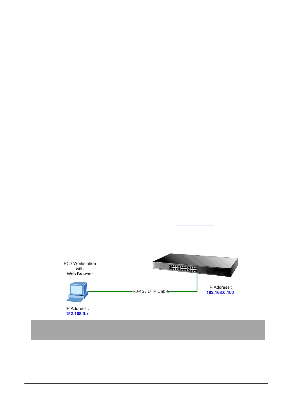
The following shows how to startup the Web Management of the Switch, please note the Switch is configured through an
Ethernet connection, make sure the manager PC must be set on the same IP subnet address, for example, the default IP
address of the Switch is 192.168.0.100 (the factory-default IP address), then the manager PC should be set at
192.168.0.xxx (where x is a number between 1 and 254, except 100), and the default subnet mask is 255.255.255.0.
Use Internet Explorer 7.0 or above Web browser, enter default IP address http://192.168.0.100
After entering the username and password (default user name and password is “admin”) in login screen
Default IP : 192.168.0.100
Default Username: admin
Default Password: admin
- 14 -
Page 15
User’s Manual of FNSW-2400PS
3.3 Logging on to the FNSW-2400PS
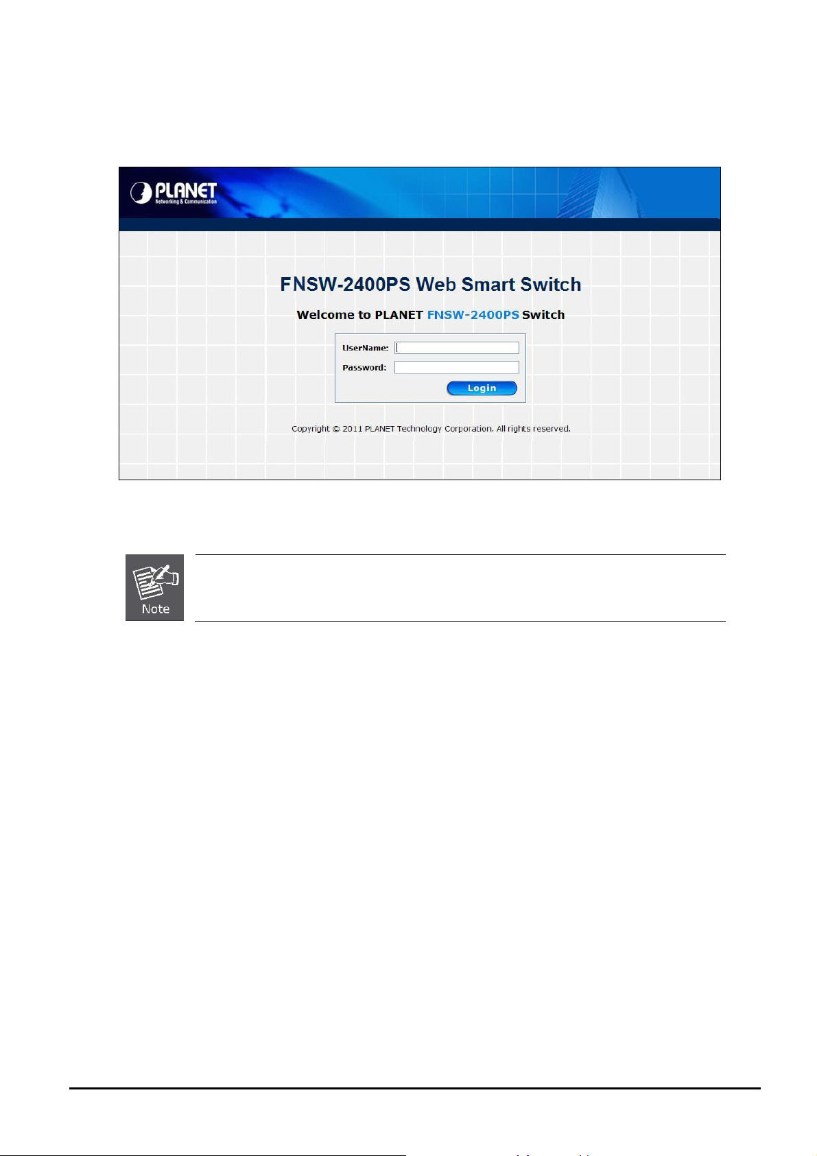
When you log on to the POE Web Smart Ethernet Switch Web interface for the first time, a sign-on string appears and you
are prompted for a Web login username and password. The factory default login username and password is admin.
Figure 3-1 POE Web Smart Ethernet Switch Web Login Screen
For security reason, please change and memorize the new password after this first setup.
- 15 -
Page 16
User’s Manual of FNSW-2400PS
a
4. WEB MANAGEMENT
To modify your PC’s IP domain to the same with POE Web Smart Ethernet Switch then use the default IP address
(192.168.0.100) to remote configure POE Web Smart Ethernet Switch through the Web interface.
4.1 Login in to the Switch
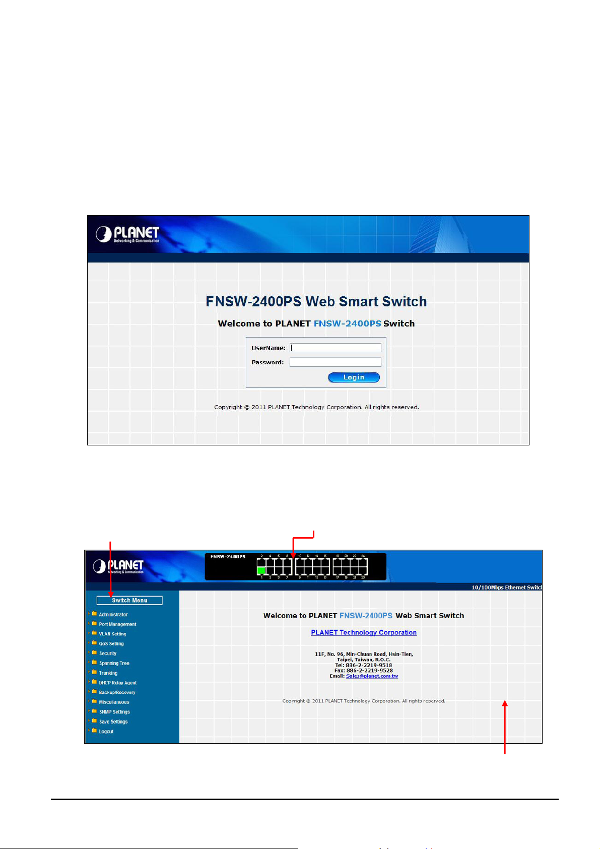
To access the Web-browser interface you must first enter the user name and password, the default user name and
password is "admin”. You will see the following screen Figure 4-1 comes out on the Web browser program:
Figure 4-1 Web Login Screen
After the User name and Password is entered, you will see the Web Main Menu screen.
The Switch Menu provide seven major management functions, the screen in Figure 4-2 appears.
Main Functions Menu
Fast Ethernet Port Link Status
Figure 4-2 Web Main Menu Screen
in Screen
M
- 16 -
Page 17
User’s Manual of FNSW-2400PS
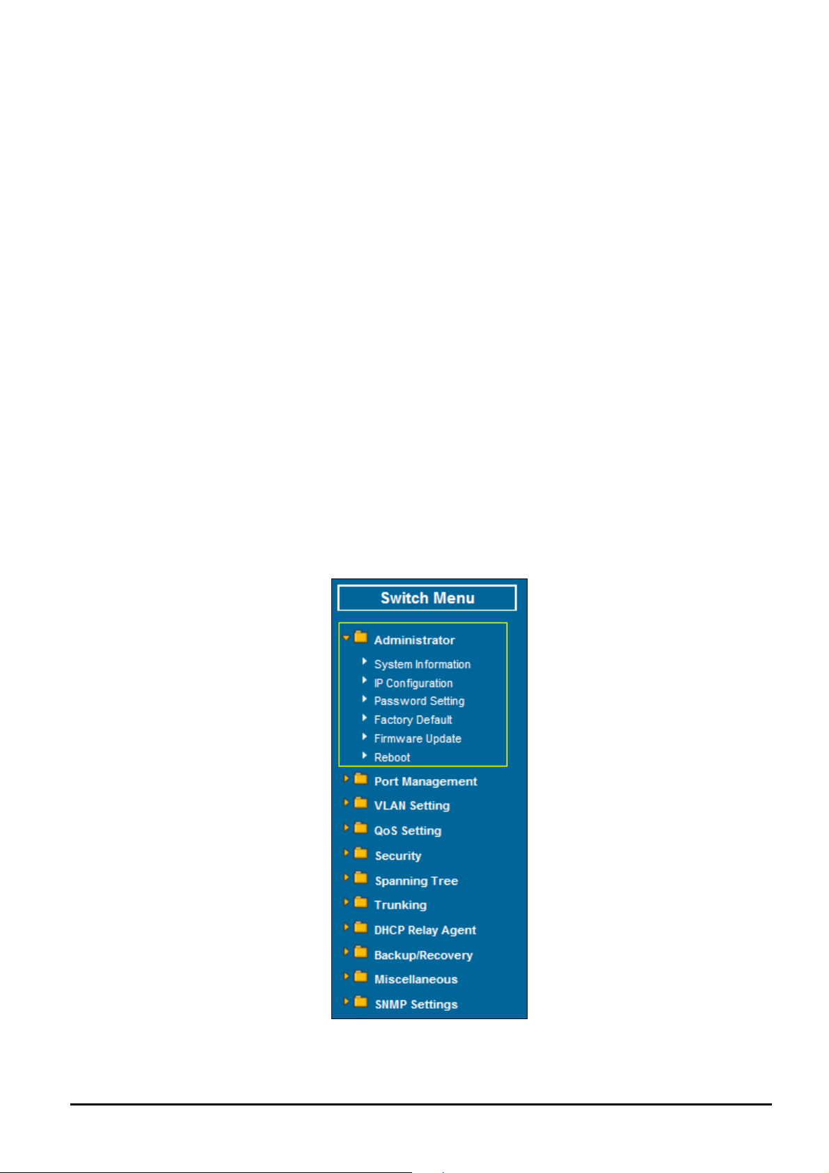
The seven items and it description shown as below:
◆ Administrator: Provide System configuration of POE Web Smart Switch. Explained in section 4.2.
◆ Port Management: Provide Port Management configuration of POE Web Smart Switch. Explained in section 4.3.
◆ VLAN Setting: Provide VLAN Setting configuration of POE Web Smart Switch. Explained in section 4.4.
◆ QoS Setting: Provide QoS Setting configuration of POE Web Smart Switch. Explained in section 4.5.
◆ Security: Provide Security Filter configuration of POE Web Smart Switch. Explained in section 4.6.
◆ Spanning Tree: Provide Spanning Tree configuration of POE Web Smart Switch. Explained in section 4.7
◆ Trunking: Provide Trunk Setting configuration of POE Web Smart Switch. Explained in section 4.8.
◆ DHCP Relay Agent: Provide DHCP Relay Agent configuration of POE Web Smart Switch. Explained in section
4.9.
◆ Backup/Recovery: Provide Backup/Recovery configuration of POE Web Smart Switch. Explained in section 4.10.
◆ Miscellaneous: Provide Misc Operation configuration of POE Web Smart Switch. Explained in section 4.11.
◆ SNMP Settings: Provide SNMP Settings configuration of POE Web Smart Switch. Explained in section 4.12.
◆ Save Settings: Provide Save function of POE Web Smart Switch. Explained in section 4.13.
◆ Logout: Provide Logout function of POE Web Smart Switch. Explained in section 4.14.
4.2 Administrator
This section provides System Information, IP Configuration, Password Setting, Factory Default, Firmware Update and
Reboot functions of POE Web Smart Ethernet Switch, the screen in Figure 4-3 appears and Table 4-1 describes the
System object of POE Web Smart Ethernet Switch.
Figure 4-3 System Web Page Screen
- 17 -
Page 18
Object Description
User’s Manual of FNSW-2400PS
System Information
IP Configuration
Password Setting
Factory Default
Firmware Update
Reboot
Display the MAC address, and Software Version, Device Description. Explained in section
4.2.1.
Allow to change the IP subnet address of POE Web Smart Ethernet Switch. Explained in
section 4.2.2.
Allow to change the username and password of POE Web Smart Ethernet Switch. Explained in
section 4.2.3.
Allow reset the POE Web Smart Ethernet Switch to factory default mode. Explained in section
4.2.4.
Allow proceed firmware upgrade process of POE Web Smart Ethernet Switch. Explained in
section 4.2.5.
Allow reboot the POE Web Smart Ethernet Switch. Explained in section 4.2.6.
Table 4-1 Descriptions of the System Web Page Screen Objects
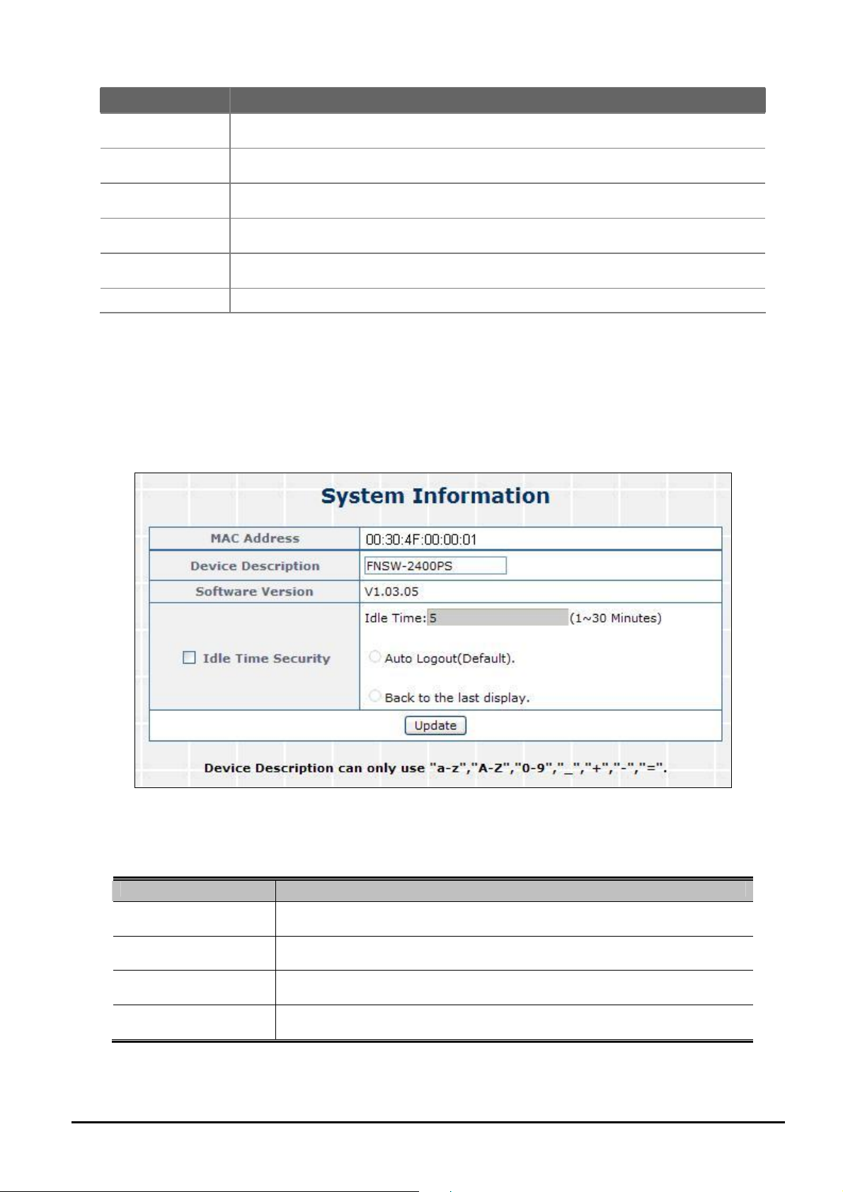
4.2.1 System Information
This section displays the MAC address and Software Version, also allow define the device description and press “Update”
button to take affect. The screen in Figure 4-4 appears.
Figure 4-4 System Information Web Page Screen
The page includes the following fields:
Object Description
• MAC Address
• Device Description
• Software Version
• Idle Time Security
Table 4-2 Descriptions of the System Information Web Page Screen Objects
- 18 -
Displays the unique hardware address assigned by manufacturer (default).
Describes the Managed Switch. Up to 15 characters is allowed for the
Device Description.
The software version of the switch.
Set idle time and behavior.
Page 19
User’s Manual of FNSW-2400PS
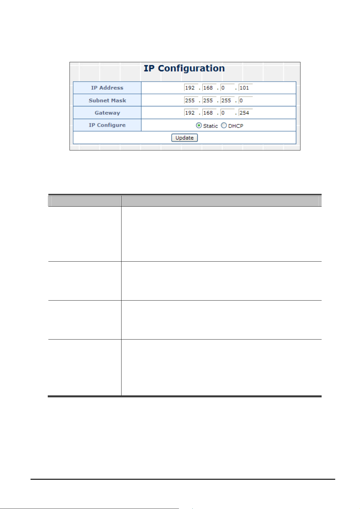
4.2.2 IP Configuration
This section provides change the IP Address, Subnet Mask and Gateway, the screen in Figure 4-5 appears.
Figure 4-5 IP Configuration Web Page Screen
The page includes the following fields:
Object Description
Assign the IP address that the network is using.
If DHCP client function is enabled, this switch is configured as a DHCP
IP Address
client. The network DHCP server will assign the IP address to the switch
and display it in this column.
The default IP is 192.168.0.100 or the user has to assign an IP address
manually when DHCP Client is disabled.
Assign the subnet mask to the IP address.
Subnet Mask
If DHCP client function is disabled, the user has to assign the subnet
mask in this column field.
The default subnet mask is 255.255.255.0.
Assign the network gateway for the switch.
Gateway
If DHCP client function is disabled, the user has to assign the gateway in
this column field.
The default gateway is 192.168.0.254.
Select static IP address or DHCP client function
When DHCP function is enabled, the POE Web Smart Ethernet Switch
will be assigned an IP address from the network DHCP server. The de-
IP Configure
fault IP address will be replaced by the assigned IP address on DHCP
server. After the user clicks Apply, a popup dialog shows up to inform the
user that when the DHCP client is enabled, the current IP will lose and
user should find the new IP on the DHCP server.
Table 4-3 Descriptions of the IP Configuration Web Page Screen Objects
- 19 -
Page 20
User’s Manual of FNSW-2400PS
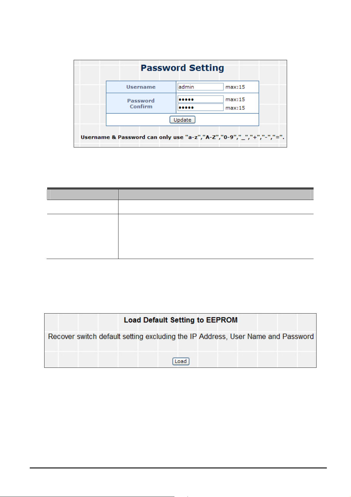
4.2.3 Password Setting
This section provides change the Username and Password, the screen in Figure 4-6 appears.
Figure 4-6 Password Setting Web Page Screen
The page includes the following fields:
Object Description
Username
Password
Confirm
Displays the user name.
Specifies the new password. The password is not displayed. As it entered
an “y” corresponding to each character is displayed in the field.
(The maximum length is 15 characters)
Confirms the new password. The password entered into second field
must be exactly the same as the password entered in the Password field.
Table 4-4 Descriptions of the Password Setting Web Page Screen Objects
4.2.4 Factory Default
This section provides reset the POE Web Smart Ethernet Switch to factory default mode, the screen in Figure 4-7 appears.
Figure 4-7 Factory Default Web Page Screen
- 20 -
Page 21
User’s Manual of FNSW-2400PS
Press “Load” button to take affect. After finish the operation, the following screen in Figure 4-8 appears and please press
“Reset” button and it will back to the Web login screen. After input default username and password then can continue the
POE Web Smart Ethernet Switch management.
Figure 4-8 Web Page Screen of Factory Default Finish
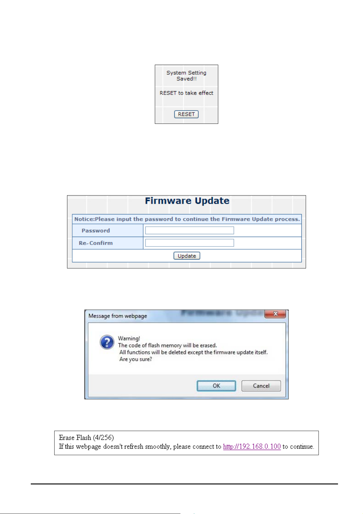
4.2.5 Firmware Update
This section provides firmware upgrade of the POE Web Smart Ethernet Switch, the screen in Figure 4-9 appears. Before
Firmware Update, it will ask for the Password to confirm this procedure.
Figure 4-9 Firmware Update Web Page Screen
Key in the password and press “Update” button to take effect, after press the “Update” button, the screen in Figure 4-10
appears. The warning message for double confirming.
Figure 4-10 Warning Message Screen
Press “OK” button for start the firmware upgrade process, the screen in Figure 4-11 appears.
Figure 4-11 Firmware Update Web page Screen
- 21 -
Page 22

User’s Manual of FNSW-2400PS
Then the following screen appears, press “Browser” button to find the firmware location administrator PC, the screen in
Figure 4-12 appears.
Figure 4-12 Firmware Update Web Page Screen
After find the firmware location from administrator PC, press “Update” button to start the firmware upgrade process. The
screen in Figure 4-13 appears.
Figure 4-13 Firmware Update Web Page Screen
When firmware upgrade process is completed then the following screen appears, please press the “continue”
button and wait for system reboot. After device reboot then can use the latest firmware of the POE Web Smart
Ethernet Switch.
Figure 4-14 Firmware Update Web Page Screen
1. Recommend to use IE 7.0 or FireFox browser tools for firmware upgrade
process.
2. Firmware upgrade needs several minutes. Please wait a while, and don’t power
off the POE Web Smart Ethernet Switch until the update progress is complete.
4.2.6 Reboot
This section allows reboot the POE Web Smart Ethernet Switch, the screen in Figure 4-15 appears.
Figure 4-15 Reboot Web Page Screen
Press “Confirm” button to reboot the POE Web Smart Ethernet Switch. After device reboot completed, the Web login
screen appears and login for further management.
- 22 -
Page 23

User’s Manual of FNSW-2400PS
4.3 Port Management
This section provides Port Configuration, Port Mirroring, Bandwidth Control, Broadcast Storm Control and Port Statistics
from POE Web Smart Ethernet Switch, the screen in Figure 4-16 appears and Table 4-5 describes the system object of
POE Web Smart Ethernet Switch.
Figure 4-16 Port Management Web Page Screen
Object Description
Port Configuration
Port Mirroring
Bandwidth Control
Broadcast Storm Control
Port Statistics
Allow to configure each port of POE Web Smart Ethernet Switch. Explained in section
4.3.1.
Allow to use port mirroring function of POE Web Smart Ethernet Switch. Explained in
section 4.3.2.
Allow to configure bandwidth control of each port from POE Web Smart Ethernet Switch.
Explained in section 4.3.3.
Allow to configure broadcast storm control of each port from POE Web Smart Ethernet
Switch. Explained in section 4.3.4.
Display each port statistics of POE Web Smart Ethernet Switch. Explained in section
4.3.5.
Table 4-5 Descriptions of the Port Management Web Page Screen Objects
- 23 -
Page 24

User’s Manual of FNSW-2400PS
4.3.1 Port Configuration
This section introduces detail settings of per port on POE Web Smart Ethernet Switch; the screen in Figure 4-17 appears
and Table 4-6 descriptions the Port Configuration objects of POE Web Smart Ethernet Switch.
Figure 4-17 Port Configuration Web Page Screen
The page includes the following fields:
Object Description
• Enable
Allow choosing all or one port of POE Web Smart Ethernet Switch for
further management, the available options is All & 01 to 24.
• Auto-Nego
Enable and Disable. Being set as Auto, the speed and duplex mode are
negotiated automatically. When you set it as Disable, you have to set the
speed and duplex mode manually.
• Speed
- 24 -
It is available for selecting when the Negotiation column is set as Force.
Page 25

User’s Manual of FNSW-2400PS
When the Negotiation column is set as Auto, this column is read-only.
• Duplex
It is available for selecting when the Negotiation column is set as Force.
When the Negotiation column is set as Auto, this column is read-only.
• Symmetric Pause
Flow Control for Full Duplex. The Device can support Pause Frames
flowing in both direction
• Asymmetric Pause
Flow Control for Full Duplex. The Device can only support Pause Frames
flowing in one direction
• Back Pressure
Flow Control for Half Duplex. A condition wherein a switch causes a
transmitting device to hold off on sending data packets until the switch
bottleneck has been eliminated
• Addr. Learning
Address learning is a service that characterizes a learning
bridge, in which the source MAC address of each received packet
is stored so that future packets destined for that address can be
forwarded only to the bridge interface on which that address is
located.
Table 4-6 Descriptions of the Port Configuration Web Page Screen Objects
4.3.2 Port Mirroring
This section introduces detail settings of Port Mirroring function of POE Web Smart Ethernet Switch; the screen in Figure
4-18 appears and Table 4-7 descriptions the Port Mirroring objects of POE Web Smart Ethernet Switch.
Figure 4-18 Port Mirroring Web Page Screen
The page includes the following fields:
Object Description
• Monitored Packets
Provide disable and enable the Port Mirroring function, the available op-
tions are Disable, RX, TX, TX & RX. Default mode is Disable.
• Destination Port
The destination port can be used to see all monitor port traffic. It can
connect destination port to LAN analyzer or Netxray.
• Source Port
The source port that want to monitor. All monitor port traffic will be copied
to destination port.
Table 4-7 Descriptions of the Port Mirroring Screen Objects
- 25 -
Page 26

User’s Manual of FNSW-2400PS
4.3.3 Bandwidth Control
This section introduces detail settings of Bandwidth Control function of POE Web Smart Ethernet Switch; the screen in
Figure 4-19 appears and Table 4-8 description the Bandwidth Control objects of POE Web Smart Ethernet Switch.
Figure 4-19 Bandwidth Control Web Page Screen
The page includes the following fields:
Object Description
• Port
• Tx Rate
• Rx Rate
Indicate port 1 to port 24
Provide 0~255, 0 for Full Speed
Provide 0~255, 0 for Full Speed
Table 4-8 Descriptions of the Bandwidth Control Screen Objects
- 26 -
Page 27

User’s Manual of FNSW-2400PS
4.3.4 Broadcast Storm Control
This section introduces detail settings of Broadcast Storm Control function of POE Web Smart Ethernet Switch; the screen
in Figure 4-20 appears.
Figure 4-20 Broadcast Storm Control Web Page Screen
The broadcast storm control is used to block the excessive broadcast packets, the number ranging from 1 to 63.
For example: The broadcast storm of the port1~6 are enabled and threshold is set to 10. The broadcast packets will be
dropped when broadcast packets are more than threshold setting (packet length is 64 bytes).
4.3.5 Port Statistics
This section introduces detail information of Port Statistics function of POE Web Smart Ethernet Switch; the screen in
Figure 4-21 appears and Table 4-9 descriptions the Port Statistics objects of POE Web Smart Ethernet Switch.
Figure 4-21 Port Statistics Web Page Screen
- 27 -
Page 28

The page includes the following fields:
Object Description
User’s Manual of FNSW-2400PS
• Counter Mode
Selection
• Port
• Transmit
• Receive
Provide different type of Ethernet traffic counter mode, the available options are shown as below:
Receive Packet & Transmit Packet
Transmit Packet & Collision
Receive Packet & Packet Drop
Receive Packet & CRC error Packet
Default mode is Receive Packet & Transmit Packet.
Indicate port 1 to port 24.
Display Transmit count value from each port.
Display Receive count value from each port.
Table 4-9 Descriptions of the Port Statistics Screen Objects
- 28 -
Page 29

User’s Manual of FNSW-2400PS
4.4 VLAN Setting
This section provides VLAN Mode, VLAN Member and Multi to 1 Setting from POE Web Smart Ethernet Switch, the
screen in Figure 4-22 appears and Table 4-10 describes the system object of POE Web Smart Ethernet Switch.
Figure 4-22 VLAN Setting Web Page Screen
Object Description
VLAN Mode
VLAN Member
Multi to 1 Setting
Allow to select VLAN mode of POE Web Smart Ethernet Switch. Explained in section 4.4.1.
Allow to Modify the VLAN member port of POE Web Smart Ethernet Switch. Explained in
section 4.4.2.
Allow to Modify and Enable the function from POE Web Smart Ethernet Switch. Explained in
section 4.4.3.
Table 4-10 Descriptions of the VLAN Setting Web Page Screen Objects
A Virtual LAN (VLAN) is a logical network grouping that limits the broadcast domain. It allows you to isolate network traffic
so only members of the VLAN receive traffic from the same VLAN members. Basically, creating a VLAN from a switch is
logically equivalent of reconnecting a group of network devices to another Layer 2 switch. However, all the network devices
are still plug into the same switch physically.
The Switch supports IEEE 802.1Q (tagged-based) and Port-Base VLAN setting in web management page. In the default
configuration, VLAN support is “No VLAN”.
- 29 -
Page 30

User’s Manual of FNSW-2400PS
Port-based VLAN
Port-based VLAN limit traffic that flows into and out of switch ports. Thus, all devices connected to a port are members of
the VLAN(s) the port belongs to, whether there is a single computer directly connected to a switch, or an entire department.
On port-based VLAN.NIC do not need to be able to identify 802.1Q tags in packet headers. NIC send and receive normal
Ethernet packets. If the packet's destination lies on the same segment, communications take place using normal Ethernet
protocols. Even though this is always the case, when the destination for a packet lies on another switch port, VLAN con-
siderations come into play to decide if the packet is dropped by the Switch or delivered.
IEEE 802.1Q Tag Base VLAN
IEEE 802.1Q (tagged) VLAN are implemented on the Switch. 802.1Q VLAN require tagging, which enables them to span
the entire network (assuming all switches on the network are IEEE 802.1Q-compliant).
VLAN allow a network to be segmented in order to reduce the size of broadcast domains. All packets entering a VLAN will
only be forwarded to the stations (over IEEE 802.1Q enabled switches) that are members of that VLAN, and this includes
broadcast, multicast and unicast packets from unknown sources.
VLAN can also provide a level of security to your network. IEEE 802.1Q VLAN will only deliver packets between stations
that are members of the VLAN. Any port can be configured as either tagging or untagging. The untagging feature of IEEE
802.1Q VLAN allows VLAN to work with legacy switches that don't recognize VLAN tags in packet headers. The tagging
feature allows VLAN to span multiple 802.1Q-compliant switches through a single physical connection and allows Span-
ning Tree to be enabled on all ports and work normally.
Any port can be configured as either tagging or untagging. The untagging feature of IEEE 802.1Q VLAN allows VLAN to
work with legacy switches that don’t recognize VLAN tags in packet headers. The tagging feature allows VLAN to span
multiple 802.1Q-compliant switches through a single physical connection and allows Spanning Tree to be enabled on all
ports and work normally.
Some relevant terms:
Tag - The act of putting 802.1Q VLAN information into the header of a packet.
Untag - The act of stripping 802.1Q VLAN information out of the packet header.
802.1Q VLAN Tags
The figure below shows the 802.1Q VLAN tag. There are four additional octets inserted after the source MAC address.
Their presence is indicated by a value of 0x8100 in the Ether Type field. When a packet's Ether Type field is equal to
0x8100, the packet carries the IEEE 802.1Q/802.1p tag. The tag is contained in the following two octets and consists of 3
bits of user priority, 1 bit of Canonical Format Identifier (CFI - used for encapsulating Token Ring packets so they can be
carried across Ethernet backbones), and 12 bits of VLAN ID (VID). The 3 bits of user priority are used by 802.1p. The VID
is the VLAN identifier and is used by the 802.1Q standard. Because the VID is 12 bits long, 4094 unique VLAN can be
identified.
The tag is inserted into the packet header making the entire packet longer by 4 octets. All of the information originally
contained in the packet is retained.
- 30 -
Page 31

User’s Manual of FNSW-2400PS
802.1Q Tag
User Priority CFI VLAN ID (VID)
3 bits 1 bits 12 bits
TPID (Tag Protocol Identifier) TCI (Tag Control Information)
2 bytes 2 bytes
Preamble
Destination
Address
The Ether Type and VLAN ID are inserted after the MAC source address, but before the original Ether Type/Length or
Logical Link Control. Because the packet is now a bit longer than it was originally, the Cyclic Redundancy Check (CRC)
must be recalculated.
Source Ad-
dress
6 bytes 6 bytes 4 bytes 2 bytes 46-1517 bytes 4 bytes
VLAN TAG
Ethernet
Type
Data FCS
Adding an IEEE802.1Q Tag
Dest. Addr. Src. Addr. Length/E. type Data Old CRC
Original Ethernet Pack-
Dest. Addr. Src. Addr. E. type Tag Length/E. type Data New CRC
Priority CFI VLAN ID
New Tagged Packet
Port VLAN ID
Packets that are tagged (are carrying the 802.1Q VID information) can be transmitted from one 802.1Q compliant network
device to another with the VLAN information intact. This allows 802.1Q VLAN to span network devices (and indeed, the
entire network – if all network devices are 802.1Q compliant).
Every physical port on a switch has a PVID. 802.1Q ports are also assigned a PVID, for use within the switch. If no VLAN
are defined on the switch, all ports are then assigned to a default VLAN with a PVID equal to 1. Untagged packets are
assigned the PVID of the port on which they were received. Forwarding decisions are based upon this PVID, in so far as
VLAN are concerned. Tagged packets are forwarded according to the VID contained within the tag. Tagged packets are
also assigned a PVID, but the PVID is not used to make packet forwarding decisions, the VID is.
Tag-aware switches must keep a table to relate PVID within the switch to VID on the network. The switch will compare the
VID of a packet to be transmitted to the VID of the port that is to transmit the packet. If the two VID are different the switch
will drop the packet. Because of the existence of the PVID for untagged packets and the VID for tagged packets, tag-aware
and tag-unaware network devices can coexist on the same network.
A switch port can have only one PVID, but can have as many VID as the switch has memory in its VLAN table to store
them.
Because some devices on a network may be tag-unaware, a decision must be made at each port on a tag-aware device
before packets are transmitted – should the packet to be transmitted have a tag or not? If the transmitting port is connected
to a tag-unaware device, the packet should be untagged. If the transmitting port is connected to a tag-aware device, the
packet should be tagged.
- 31 -
Page 32

User’s Manual of FNSW-2400PS
Default VLANs
The Switch initially configures one VLAN, VID = 1, called "default." The factory default setting assigns all ports on the
Switch to the "default". As new VLAN are configured in Port-based mode, their respective member ports are removed
from the "default."
Base on the Switch chipset specification, the Switch supports SVL(Shared VLAN Learning) ,
all VLAN groups share the same Layer 2 learned MAC address table.
4.4.1 VLAN Mode
This section provides VLAN Configuration from POE Web Smart Ethernet Switch, the screen in Figure 4-23 appears and
Table 4-11 describes the VLAN Configuration object of POE Web Smart Ethernet Switch.
Figure 4-23 VLAN Mode Web Page Screen
The page includes the following fields:
Object Description
• VLAN Mode
• Change VLAN mode
Provide different VLAN operation mode, the available options are shown as below:
Tag Base VLAN
Port Based VLAN
Default mode is Port Base VLAN.
Changing current VLAN mode of POE Web Smart Ethernet Switch.
Button
Table 4-11 Descriptions of the VLAN Mode Screen Objects
- 32 -
Page 33

User’s Manual of FNSW-2400PS
4.4.1.1 Port Base VLAN Mode
The default VLAN mode is “Port Based VLAN” from the VLAN Mode. The screen in Figure 4-24 appears.
Figure 4-24 Port Base VLAN Mode Web Page Screen
4.4.1.2 Tag Base VLAN Mode
This section introduces detail information of IEEE 802.1Q VLAN function of POE Web Smart Ethernet Switch. To execute
“Tag Base VLAN” mode from VLAN Mode, press “Change VLAN mode” button to enable the 802.1Q VLAN function.
One screen in Figure 4-25 will appear to ask for confirming to swap VLAN mode.
Figure 4-25 Change VLAN Mode Warning Web Page Screen
Press “Continue” button, the current Port-base VLAN mode will swap to the Tag Base VLAN mode. The Screen in Figure
4-26 will appear Table 4-12 description the Tag Base VLAN mode objects of Web Smart Switch press “Update” button to
take affect.
Figure 4-26 802.1Q VLAN Configuration Web Page Screen
- 33 -
Page 34
The page includes the following fields:
Object Description
User’s Manual of FNSW-2400PS
• VLAN Mode
• VLAN Tag Mode
• Add Tag Type
Table 4-12 Descriptions of the Tag Base VLAN Setting Screen Objects
Provide different VLAN operation mode, the options are shown as below:
Tag Base VLAN
Port Based VLAN
Include Two mode:
Tag / Untag base on Port
Tag / Untag base on Port
Customize Tag or Untage for per port
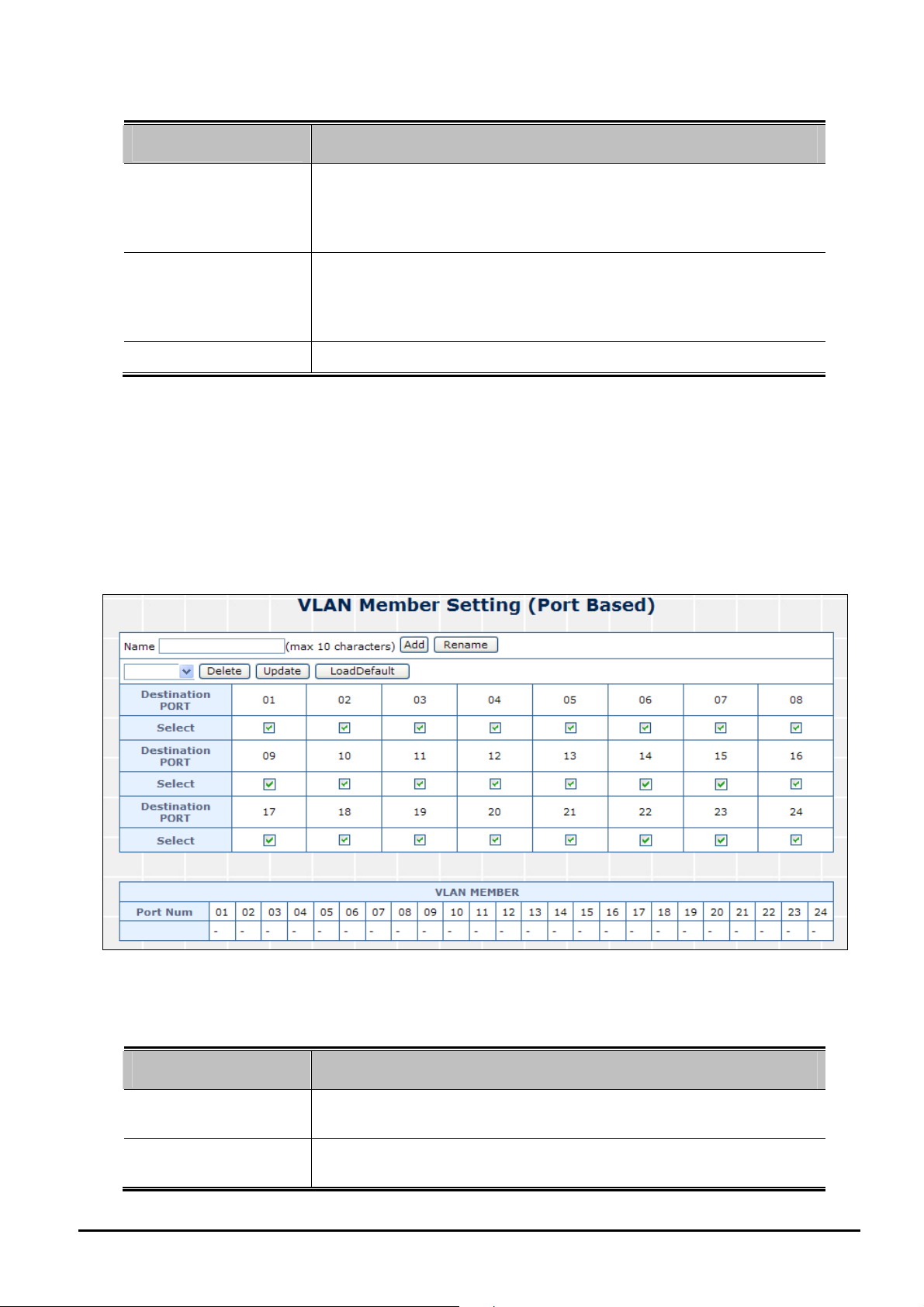
4.4.2 VLAN Member
This section introduces detail information of VLAN Member function of POE Web Smart Ethernet Switch. It has
two kind of VLAN Member types, one is for Port Base VLAN mode and one is for Tag Base VLAN mode which
depend on your .
the type of VLAN Member objects of Web Smart Switch.
The Screen Figure 4-27 & 4-28 show the type of VLAN Member and the Table 4-13 & 4-14 description
Figure 4-27 VLAN Member Setting (Port Based) Web Page Screen
The page includes the following fields:
Object Description
• Name
• Add Button
- 34 -
Assign and display different VLAN name from multi-port based VLAN groups. Up
to maximum 10 characters allow.
Press this button for add a new port based VLAN groups. Up to maximum 24 port
based VLAN groups.
Page 35

User’s Manual of FNSW-2400PS
• Rename Button
• Delete Button
• Update Button
• Load Default Button
Table 4-13 Descriptions of the VLAN Member Setting (Port Based) Screen Objects
Allow to change the Name
Allow to delete the group which has been created
Allow to update the group when change/modify the port members
Back to VLAN member default, all of groups will be clear
Figure 4-28 VLAN Member Setting (Tag Based) Web Page Screen
The page includes the following fields:
Object Description
• VID (1~4094)
• Name
• Add Button
• Delete Button
• Update Button
Table 4-14 Descriptions of the VLAN Member Setting (Tag Based) Screen Objects
- 35 -
Display different VLAN ID from multi-Tag Base VLAN mode groups.
Assign and display different VLAN name from multi-Tag Base VLAN VLAN
groups. Up to maximum 10 characters allow.
Press this button for add a new port based VLAN groups. Up to maximum 24 port
based VLAN groups.
Allow to delete the group which has been created
Allow to update the group when change/modify the port members
Page 36

User’s Manual of FNSW-2400PS
4.4.3 Multi to 1 Setting
This setting is exclusive to VLAN setting on ”VLAN member setting “. When VLAN member setting is updated, multi-to-1
setting will be void and vice versa. The “disable port” means the port is excluded in this setting. All ports excluded in this
setting are treated as the same VLAN group. The Screen Figure 4-29 shows the Multi to 1 Setting.
Figure 4-29 Multi to 1 Setting Web Page Screen
- 36 -
Page 37

User’s Manual of FNSW-2400PS
4.5 QoS Setting
This function provides QoS Setting of Web Smart Switch; the screen in Figure 4-30 appears and Table 4-15 descriptions
the QoS Setting of Web Smart Switch.
Figure 4-30 QoS Setting Web Page Screen
The page includes the following fields:
Object Description
• Priority Mode
• Class of Service
Configuration
Provide three different Priority polices on Web Smart Switch.
section 4.5.1.
Provide four different polices on each port of Web Smart Switch.
plained in section 4.5.2.
Table 4-15 Descriptions of the QoS Setting Screen Objects
Explained in
Ex-
4.5.1 Priority Mode
This section introduces detail information of Priority Mode of Web Smart Switch; the screen in Figure 4-31 appears and
Table 4-16 descriptions the Priority Mode of Web Smart Switch.
- 37 -
Page 38

Figure 4-31 Priority Mode Web Page Screen
The page includes the following fields:
Object Description
User’s Manual of FNSW-2400PS
• Priority Mode
Provide three different Priority polices on Web Smart Switch, the available options are shown as below:
Fist-In-First-Out
All-High-Before-Low
4 Queue WRR = Q3 and Q4 Low weight (0-16 range) : Q1 and Q2
High weight (0-16 range)
Default mode is First-In-First-Out.
Table 4-16 Descriptions of the Priority Mode Screen Objects
4.5.2 Class of Service
This section introduces detail information of Class of Service Configuration of Web Smart Switch; the Class of Service has
four types of services, TCP / UDP port, IP TOS / DS, 802.1p and physical port. The switch treats TCP / UDP port, IP TOS
/ DS, 802.1p and physical port CoS scheme in the following priority. TCP / UDP > IP TOS / DS > 802.1p > physical port.
This means TCP / UDP CoS will override all other settings.The screen in Figure 4-32 appears.
- 38 -
Page 39

User’s Manual of FNSW-2400PS
- 39 -
Page 40

User’s Manual of FNSW-2400PS
Figure 4-32 Class of Service Web Page Screen
- 40 -
Page 41

User’s Manual of FNSW-2400PS
4.6 Security
This function provides Security of POE Web Smart Ethernet Switch; the screen in Figure 4-33 appears and Table 4-17
descriptions the Security of POE Web Smart Ethernet Switch.
Figure 4-33 Security Filter Web Page Screen
The page includes the following fields:
Object Description
• MAC Address
Binding
• MAC Address Scan
• TCP/UDP Filter
• IP Address Filter
Table 4-17 Descriptions of the Security Filter Web Page Screen Objects
- 41 -
Allow to define three MAC Address on per port of POE Web Smart
Ethernet Switch.
Explained in section 4.7.1.
Allow to detect the MAC on per port of POE Web Smart Ethernet Switdh.
Explained in section 4.7.2
.
Allow to define the filter policy of TCP / UDP flow on POE Web Smart
Ethernet Switch.
Explained in section 4.7.3.
Allow to define the filter policy of IP flow on POE Web Smart Ethernet
Switch.
Explained in section 4.7.4.
Page 42
User’s Manual of FNSW-2400PS
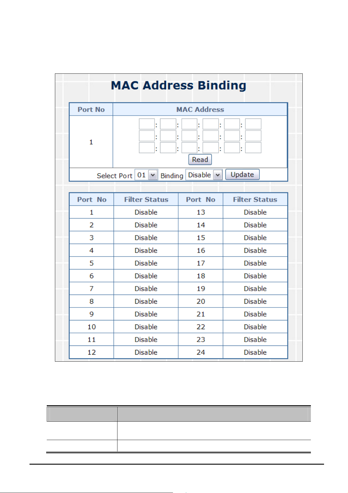
4.6.1 MAC Address Binding
This section introduces detail information of MAC Address Binding of POE Web Smart Ethernet Switch; the screen in
Figure 4-34 appears and Table 4-18 descriptions the MAC Address Binding of POE Web Smart Ethernet Switch.
Figure 4-34 MAC Address Binding Web Page Screen
The page includes the following fields:
Object Description
• MAC Address
Allow to input three MAC Address on per port of POE Web Smart
Ethernet Switch.
• Select Port
- 42 -
Allow to select port 1 to port 24.
Page 43

User’s Manual of FNSW-2400PS
• Binding
Allow to Disable or Enable the binding function on each port of POE Web
Smart Ethernet Switch.
• Port
• Binding Status
Indicate port 1 to port 24.
Display Binding Status from each port of POE Web Smart Ethernet
Switch.
Table 4-18 Descriptions of the MAC Address Binding Screen Objects
4.6.2 TCP / UDP Scan
This section is help to detect the MAC on per port of POE Web Smart Ethernet Switch; the screen in Figure 4-35 appears
and Table 4-19 descriptions the MAC Address Scan of POE Web Smart Ethernet Switch.
Figure 4-35 MAC Address Binding Web Page Screen
Object Description
• Port Select
• MAC Address
• Entry Status
Allow to select port 1 to port 24.
Display the MAC address on per port.
Display the MAC Status from each port of POE Web Smart Ethernet
Switch.
Table 4-19 Descriptions of the MAC Address Scan Screen Objects
4.6.3 TCP / UDP Filter
This section introduces detail information of TCP / UDP Filter of POE Web Smart Ethernet Switch; the screen in Figure
4-36 appears and Table 4-20 descriptions the TCP / UDP Filter Configuration of POE Web Smart Ethernet Switch.
- 43 -
Page 44

User’s Manual of FNSW-2400PS
Figure 4-36 TCP / UDP Filter Web Page Screen
The page includes the following fields:
Object Description
• Function Enable
Allow to Disable or Enable the TCP / UDP Filter function. Default mode is
Disable.
• Port Filtering Rule
• Secure Port
• FTP(20,21)
• SSH(22)
• TELNET(23)
• SMTP(25)
• DNS(53)
• TFTP(69)
• HTTP(80,8080)
Allow to Forward or Block the Port Filtering Rule. Default mode is Block.
Indicate port 1 to port 24. Click specific port for filtering.
• POP3(110)
• NEWS(119)
• SNTP(123)
• NetBIOS(137~139)
Allow to choose list protocol for filtering
• IMAP(143,220)
• SNMP(161,162)
- 44 -
Page 45

User’s Manual of FNSW-2400PS
• HTTPS(443)
• MSN(1863)
• XRD_RDP(3389)
• QQ(4000,8000)
• ICQ(5190)
• Yahoo(5050)
• BOOTP_DHCP(67,68)
• User_Define_a
• User_Define_b
• User_Define_c
Table 4-20 Descriptions of the TCP / UDP Filter Configuration Screen Objects
4.6.4 IP Address Filter
This section introduces detail information of IP Address Filter of POE Web Smart Ethernet Switch; the screen in Figure
4-37 appears and Table 4-21 descriptions the TCP / UDP Filter Configuration of POE Web Smart Ethernet Switch.
Figure 4-37 IP Address Filter Web Page Screen
- 45 -
Page 46

Object Description
User’s Manual of FNSW-2400PS
• Set NO.
• IP Address / Switch
Allow to select No. 1 to 32.
Enter the IP address and Port NO. 1 to 24.
Port
• Range
Two choices:
1. Check Source IP Address
2. Check Destination IP Address
• Rule
Four Rules:
1. IP mismatch can pass
2. IP match can pass
3. IP match and port match can pass
4. IP match and port mismatch can pass
• Port NO.
Table 4-21 Descriptions of the IP Address Filter Configuration Screen Objects
Allow to select port 1 to port 24.
4.7 Spanning Tree
This function provides Spanning Tree of POE Web Smart Ethernet Switch; the screen in Figure 4-38 appears and Table
4-22 descriptions the Spanning Tree of POE Web Smart Ethernet Switch.
Figure 4-38 Spanning Tree Web Page Screen
- 46 -
Page 47

The page includes the following fields:
Object Description
User’s Manual of FNSW-2400PS
• STP Bridge Settings
• STP Port Settings
• Loopback Detection
Table 4-22 Descriptions of the Spanning Tree Web Page Screen Objects
Allow to sets STP bridge of POE Web Smart Ethernet Switch.
in section 4.8.1.
Allow to define STP on per port of POE Web Smart Ethernet Switch.
Explained in section 4.8.2.
Allow to sets loopback detection on POE Web Smart Ethernet Switch.
Explained in section 4.8.3.
Explained
4.7.1 STP Bridge Settings
This section introduces detail information of STP Bridge Settings of POE Web Smart Ethernet Switch; the screen in Figure
4-39 appears and Table 4-23 descriptions the STP Bridge Settings Configuration of POE Web Smart Ethernet Switch.
Figure 4-39 STP Bridge Settings Web Page Screen
The page includes the following fields:
Object Description
• STP Mode
The STP mode setting. Valid values are Disable, STP & RSTP. Default
mode is Disable.
- 47 -
Page 48

User’s Manual of FNSW-2400PS
• Bridge Priority
• Hello Time
• Max Age
• Forward Delay
• Bridge Status
• Root Status
Table 4-23 Descriptions of the STP Bridge Settings Configuration Screen Objects
The switch with the lowest value has the highest priority and is selected
as the root. If the value is changed, the user must reboot the switch.
The value must be a multiple of 4096 according to the protocol standard
rule.
The time that controls the switch to send out the BPDU packet to check
STP current status.
Enter a value between 1 through 10.
The number of seconds a switch waits without receiving Spanning-tree
Protocol configuration messages before attempting a reconfiguration.
Enter a value between 6 through 40.
The number of seconds a port waits before changing from its Rapid
Spanning-Tree Protocol learning and listening states to the forwarding
state.
Enter a value between 4 through 30.
The Status of Bridge.
The Status of Root.
4.7.2 STP Port Settings
This section introduces detail information of STP Port Settings of POE Web Smart Ethernet Switch; the screen in Figure
4-40 appears and Table 4-24 descriptions the STP Port Settings Configuration of POE Web Smart Ethernet Switch.
Figure 4-40 STP Port Settings Web Page Screen
- 48 -
Page 49

The page includes the following fields:
Object Description
User’s Manual of FNSW-2400PS
• Port No.
• Priority (0~240)
• Root Path Cost
(1~200,000,000)
• Port No.
• RPC
• Priority
• State
Allow choosing one port of POE Web Smart Ethernet Switch for further
management, the available options is 01 to 24.
Decide which port should be blocked by setting its priority as the lowest.
Enter a number between 0 and 240.
The value of priority must be the multiple of 16.
The cost of the path to the other bridge from this transmitting bridge at the
specified port.
Enter a number 1 through 200,000,000.
Default value is Auto.
The switch port number of the logical STP port.
Root Path Cost. For the Root Bridge this is zero. For all other Bridges, it is
the sum of the Port Path Costs on the least cost path to the Root Bridge.
Display current priority for each port.
The current STP port state. The port state can be one of the following
values:
Alternate
Back Up
• Status
• Designated Bridge
• Designated Port
Root Port
Designated Port
The current STP port status. The port status can be one of the following
values:
Listening
Blocking
Learning
Forwarding
ID of the STP gridge who designated the root port
Port number of the bridge from where the bridge designated the root port
Table 4-24 Descriptions of the STP Port Settings Configuration Screen Objects
- 49 -
Page 50

User’s Manual of FNSW-2400PS
4.7.3 Loopback Detection Settings
This section introduces detail information of Loopback Detection Settings of POE Web Smart Ethernet Switch; the screen
in Figure 4-41 appears and Table 4-25 descriptions the Loopback Detection Settings Configuration of POE Web Smart
Ethernet Switch.
Figure 4-41 Loopback Detection Settings Web Page Screen
The page includes the following fields:
Object Description
• Loopback Detect
Function
• Auto Wake Up
Allow to Disable or Enable the Loopback Detect Function. Default mode
is Disable.
Allow to Disable or Enable the Auto Wake Up function. Default mode is
Disable.
• Wake-Up Time In-
terval
Table 4-25 Descriptions of the Loopback Detection Settings Configuration Screen Objects
Provide 5 ~ 250 sec different interval time for wake-up time of POE Web
Smart Ethernet Switch. Default mode is 10 sec.
- 50 -
Page 51

User’s Manual of FNSW-2400PS
4.8 Trunking
Port link aggregations (Port Trunking) can be used to increase the bandwidth of a network connection or to ensure fault
recovery. Link aggregation lets you group up to 4 consecutive ports into a single dedicated connection between any two
the Switch or other Layer 2 switches. However, before making any physical connections between devices, use the Link
aggregation Configuration menu to specify the link aggregation on the devices at both ends. When using a port link ag-
gregation, note that:
。 The ports used in a link aggregation must all be of the same media type (RJ-45, 100 Mbps).
。 The ports that can be assigned to the same link aggregation have certain other restrictions (see below).
。 Ports can only be assigned to one link aggregation.
。 The ports at both ends of a connection must be configured as link aggregation ports.
。 None of the ports in a link aggregation can be configured as a mirror source port or a mirror target port.
。 Enable the link aggregation prior to connecting any cable between the switches to avoid creating a data loop.
。 Disconnect all link aggregation port cables or disable the link aggregation ports before removing a port link aggre-
gation to avoid creating a data loop.
It allows a maximum of 4 ports to be aggregated at the same time and up to 2 groups. If the group is defined as
a local static link aggregation group, then the number of ports must be the same as the group member ports.
This function allows to configuring the trunk function. It provides up to two trunk groups and each trunk group provides 4
member ports. Also provide four various Trunk Hash Algorithm policies for selection. The screen in Figure 4-42 appears
and Table 4-26 description the Trunk Setting objects of POE Web Smart Ethernet Switch.
- 51 -
Page 52

User’s Manual of FNSW-2400PS
Figure 4-42 Trunk Setting Web Page Screen
The page includes the following fields:
Object Description
• System Priority A value which is used to identify the active LACP. The Managed Switch with the
lowest value has the highest priority and is selected as the active LACP peer of
the trunk group.
• Link Aggregation
Algorithm
Provide different algorithm method of link aggregation, the available options are
shown as below:
MAC Src&Dst
MAC Source
Default mode is MAC Src&Dst.
• Member Allow to click specific port as member port from different link groups.
Default link group 1 is included M1, M2, M3, M4.
Default link group 2 is included M1, M2, M3, M4.
• State
Allow disable or enable port trunk from POE Web Smart Ethernet Switch,
the available options are Enable and Disable. Default mode is Disable.
- 52 -
Page 53

User’s Manual of FNSW-2400PS
• Type
• Operation Key
• Time Out
• Activity
Table 4-26 Descriptions of the Trunk Setting Screen Objects
4.9 DHCP Relay Agent
Allow to selects port trunk type from POE Web Smart Ethernet Switch, the
available options are LACP and Static. Default mode is LACP.
The LACP operation key must be set to the same value for ports that
belong to the same LAG.
Range: 1-65535;
Default Link Group 1: 1
Default Link Group 2: 2
The time out configuration mode command assigns an administrative
LACP timeout. To reset the default administrative LACP timeout use the
no form of this command
Long Time Out
Short Time Out
Default mode is Short Time Out.
, the available options are shown as below:
Allow link group to automatically sends LACP protocol packets or not.
Default mode is Passive.
This function provides DHCP Relay Agent of POE Web Smart Ethernet Switch; the screen in Figure 4-43 appears and
Table 4-27 descriptions the DHCP Relay Agent of POE Web Smart Ethernet Switch.
Figure 4-43 DHCP Relay Agent Web Page Screen
- 53 -
Page 54

The page includes the following fields:
Object Description
User’s Manual of FNSW-2400PS
• DHCP Relay Agent
• Relay Server
• VLAN MAP Relay
Agent
Table 4-27 Descriptions of the DHCP Relay Agent Web Page Screen Objects
Allow to sets DHCP Relay Agent of POE Web Smart Ethernet Switch.
Explained in section 4.9.1.
Allow to sets Relay Server of POE Web Smart Ethernet Switch.
plained in section 4.9.2.
Ex-
Allow define VLAN MAP Relay Agent of POE Web Smart Ethernet
Switch.
Explained in section 4.9.3.
4.9.1 DHCP Relay Agent
This section introduces detail information of DHCP Relay Agent of POE Web Smart Ethernet Switch; the screen in Figure
4-44 appears and Table 4-28 descriptions the STP Bridge Settings Configuration of POE Web Smart Ethernet Switch.
Figure 4-44 DHCP Relay Agent Web Page Screen
The page includes the following fields:
Object Description
• DHCP Relay State
Allow to Disable or Enable the DHCP Relay State Function. Default
mode is Disable.
• DHCP Relay Hops
Count Limit (1-16)
This field allows an entry between1 and1 6 to define the maximum
number of router hops DHCP/BOOTP messages can be forwarded
across. The default hop count is 16.
• DHCP Relay Option
82 State
Table 4-28 Descriptions of the DHCP Relay Agent Configuration Screen Objects
Allow to Disable or Enable the DHCP Relay Option 82 State Function.
Default mode is Disable.
- 54 -
Page 55

User’s Manual of FNSW-2400PS
4.9.2 Relay Server
This section introduces detail information of Relay Server of POE Web Smart Ethernet Switch; the screen in Figure 4-45
appears and Table 4-29 descriptions the Relay Server Configuration of POE Web Smart Ethernet Switch.
Figure 4-45 Relay Server Web Page Screen
The page includes the following fields:
Object Description
• DHCP Server IP
Table 4-29 Descriptions of Relay Server Configuration Screen Objects
Assign the DHCP Server IP address.
4.9.3 VLAN MAP Relay Agent
This section introduces detail information of VLAN MAP Relay Agent of POE Web Smart Ethernet Switch; the screen in
Figure 4-46 appears and Table 4-30 descriptions the VLAN MAP Relay Agent Configuration of POE Web Smart Ethernet
Switch.
Figure 4-46 VLAN MAP Relay Agent Web Page Screen
The page includes the following fields:
Object Description
• VLAN ID
• Map Server IP
Table 4-30 Descriptions of the VLAN MAP Relay Agent Configuration Screen Objects
- 55 -
The VLAN ID for the entry.
Select the server IP that you want to filter.
Page 56

User’s Manual of FNSW-2400PS
4.10 Backup/Recovery
This function provides Backup/Recovery of POE Web Smart Ethernet Switch; the screen in Figure 4-47 appears and Table
4-31 descriptions the Backup/Recovery of POE Web Smart Ethernet Switch.
Figure 4-47 Backup/Recovery Web Page Screen
The page includes the following fields:
Object Description
• Backup (Switch Æ
Allow to backup current configuration to PC.
PC)
• Recovery (PC Æ
Switch)
Allow to recovery current configuration to switch. Use “Browser” button to
select file which you want to reload to switch and type in the switch
password.
Table 4-31 Descriptions of the Backup/Recovery Screen Objects
- 56 -
Page 57

User’s Manual of FNSW-2400PS
4.11 Miscellaneous
This function provides Miscellaneous of POE Web Smart Ethernet Switch; the screen in Figure 4-48 appears and Table
4-32 descriptions the Miscellaneous of POE Web Smart Ethernet Switch.
Figure 4-48 Miscellaneous Web Page Screen
The page includes the following fields:
Object Description
• Miscellaneous
Settings
• IGMP Static Router
Settings
Allow to sets DHCP Relay Agent of POE Web Smart Ethernet Switch.
Explained in section 4.11.1.
Allow to sets IGMP Static Router Settings of POE Web Smart Ethernet
Switch.
Table 4-32 Descriptions of the Miscellaneous Screen Objects
Explained in section 4.11.2.
4.11.1 Miscellaneous Settings
This function provides Miscellaneous Settings of POE Web Smart Ethernet Switch; the screen in Figure 4-49 appears and
Table 4-33 descriptions the Miscellaneous Settings of POE Web Smart Ethernet Switch.
- 57 -
Page 58

User’s Manual of FNSW-2400PS
Figure 4-49 Misc Operation Web Page Screen
The page includes the following fields:
Object Description
• Output Queue Aging
Time
Allow define the Output Queue Aging Time of POE Web Smart Ethernet
Switch; the available options are Disable, 200ms, 400ms, 600ms and
800ms. Default mode is Disable.
• VLAN Striding
Allow Disable or Enable the VLAN Striding function of POE Web Smart
Ethernet Switch. Default mode is Disable.
• IGMP Snooping V1 &
V2
• VLAN Uplink Setting
Allow Disable or Enable the IGMP Snooping V1 & V2 function of POE
Web Smart Ethernet Switch. Default mode is Disable.
Allow different VLAN use their individual uplink port to forward packets. In
a normal application, “only one “uplink port can be selected in a switch.
Table 4-33 Descriptions of the Misc Operation Screen Objects
4.11.2 IGMP Static Router Settings
This function provides IGMP Static Router Settings of POE Web Smart Ethernet Switch; the screen in Figure 4-50 appears
and Table 4-34 descriptions the IGMP Static Router Settings of POE Web Smart Ethernet Switch.
Figure 4-50 Misc Operation Web Page Screen
- 58 -
Page 59

The page includes the following fields:
Object Description
User’s Manual of FNSW-2400PS
• Select Port No.
Table 4-34 Descriptions of the IGMP Static Router Settings Screen Objects
Allow to select specific port for IGMP Static feature
4.12 SNMP Settings
This function provides SNMP Settings of POE Web Smart Ethernet Switch; the screen in Figure 4-51 appears and Table
4-35 descriptions the SNMP Settings of POE Web Smart Ethernet Switch.
Figure 4-51 SNMP Settings Web Page Screen
The page includes the following fields:
Object Description
• Community Name
• Access Right
Indicates the community name.
Defines the group access rights. The possible field values are:
Read/Write
Read Only
• System Description
An administratively assigned name for this managed node. Default de-
scription is FNSW-2400PS.
- 59 -
Page 60

User’s Manual of FNSW-2400PS
• System Contact
The textual identification of the contact person for this managed node.
Default contact is Planet.
• System Location
The physical location of this node (e.g., telephone closet, 3rd floor). De-
fault contact is Planet.
• Trap State
Allow Disable or Enable the trap state function of POE Web Smart
Ethernet Switch. Default mode is Enable.
Table 4-35 Descriptions of the SNMP Settings Screen Objects
4.13 Save Settings
This section provide Web Save Settings function on POE Web Smart Ethernet Switch, after choose this function and the
following screen appears in Figure 4-52. Please press “Save” button to save all of settings of the switch. Otherwise, the
switch will use the last time saved values after rebooted.
Figure 4-52 Save Settings Page Screen
4.14 Logout
This section provide Web logout function on POE Web Smart Ethernet Switch, after choose this function and the following
screen appears in Figure 4-53. Please press “Yes” button to take effect and Login Web Screen appears. Please re-login
the POE Web Smart Ethernet Switch for further management.
Figure 4-53 Logout Web Page Screen
- 60 -
Page 61

User’s Manual of FNSW-2400PS
5. SWITCH OPERATION
5.1 Address Table
The Switch is implemented with an address table. This address table composed of many entries. Each entry is used
to store the address information of some node in network, including MAC address, port no, etc. This information
comes from the learning process of Ethernet Switch.
5.2 Learning
When one packet comes in from any port. The Switch will record the source address, port no. And the other related
information in address table. This information will be used to decide either forwarding or filtering for future packets.
5.3 Forwarding & Filtering
When one packet comes from some port of the Ethernet Switching, it will also check the destination address besides
the source address learning. The Ethernet Switching will lookup the address-table for the destination address. If not
found, this packet will be forwarded to all the other ports except the port which this packet comes in. And these ports
will transmit this packet to the network it connected. If found, and the destination address is located at different port
from this packet comes in, the Ethernet Switching will forward this packet to the port where this destination address is
located according to the information from address table. But, if the destination address is located at the same port with
this packet comes in, then this packet will be filtered. Thereby increasing the network throughput and availability.
5.4 Store-and-Forward
Store-and-Forward is one type of packet-forwarding techniques. A Store-and Forward Ethernet Switching stores the
incoming frame in an internal buffer, do the complete error checking before transmission. Therefore, no error packets
occurrence, it is the best choice when a network needs efficiency and stability.
The Ethernet Switch scans the destination address from the packet-header, searches the routing table provided for
the incoming port and forwards the packet, only if required. The fast forwarding makes the switch attractive for con-
necting servers directly to the network, thereby increasing throughput and availability. However, the switch is most
commonly used to segment existing hubs, which nearly always improves overall performance. An Ethernet Switching
can be easily configured in any Ethernet network environment to significantly boost bandwidth using conventional
cabling and adapters.
Due to the learning function of the Ethernet switching, the source address and corresponding port number of each
incoming and outgoing packet are stored in a routing table. This information is subsequently used to filter packets
whose destination address is on the same segment as the source address. This confines network traffic to its re-
spective domain, reducing the overall load on the network.
The Switch performs "Store and forward" therefore, no error packets occur. More reliably, it reduces the
re-transmission rate. No packet loss will occur.
- 61 -
Page 62

User’s Manual of FNSW-2400PS
5.5 Auto-Negotiation
The STP ports on the Switch have built-in "Auto-negotiation". This technology automatically sets the best possible
bandwidth when a connection is established with another network device (usually at Power On or Reset). This is done
by detect the modes and speeds at the second of both device is connected and capable of, both 10Base-T and
100Base-TX devices can connect with the port in either Half- or Full-Duplex mode.
- 62 -
Page 63

User’s Manual of FNSW-2400PS
6. POWER OVER ETHERNET OVERVIEW
What is PoE?
Based on the global standard IEEE 802.3af, PoE is a technology for wired Ethernet, the most widely installed local area
network technology adopted today. PoE allows the electrical power necessary for the operation of each end-device to be
carried by data cables rather than by separate power cords. New network applications, such as IP Cameras, VoIP Phones,
and Wireless Networking, can help enterprises improve productivity. It minimizes wires that must be used to install the
network for offering lower cost, and less power failures.
IEEE802.3af also called Data Terminal equipment (DTE) power via Media dependent interface (MDI) is an international
standard to define the transmission for power over Ethernet. The 802.3af is delivering 48V power over RJ-45 wiring. Be-
sides 802.3af also define two types of source equipment: Mid-Span and End-Span.
Mid-Span
Mid-Span device is placed between legacy switch and the powered device. Mid-Span is tap the unused wire pairs 4/5
and 7/8 to carry power, the other four is for data transmit.
End-Span
End-Span device is direct connecting with power device. End-Span could also tap the wire 1/2 and 3/6.
PoE System Architecture
The specification of PoE typically requires two devices: the Powered Source Equipment (PSE) and the Powered Device
(PD). The PSE is either an End-Span or a Mid-Span, while the PD is a PoE-enabled terminal, such as IP Phones, Wireless
LAN, etc. Power can be delivered over data pairs or spare pairs of standard CAT-5 cabling.
How Power is Transferred Through the Cable
A standard CAT5 Ethernet cable has four twisted pairs, but only two of these are used for 10BASE-T and 100BASE-T. The
specification allows two options for using these cables for power, shown in Figure 2 and Figure 3:
The spare pairs are used. Figure 2 shows the pair on pins 4 and 5 connected together and forming the positive / negative
supply, and the pair on pins 7 and 8 connected and forming the positive / negative supply. (In fact, a late change to the
spec allows either polarity to be used).
Figure 1 - Power Supplied over the Spare Pins
- 63 -
Page 64

User’s Manual of FNSW-2400PS
The data pairs are used. Since Ethernet pairs are transformer coupled at each end, it is possible to apply DC power to the
center tap of the isolation transformer without upsetting the data transfer. In this mode of operation the pair on pins 3 and
6 and the pair on pins 1 and 2 can be of either polarity.
Figure 2 - Power Supplied over the Data Pins
When to install PoE?
Consider the following scenarios:
• You're planning to install the latest VoIP Phone system to minimize cabling building costs when your company moves
into new offices next month.
• The company staff has been clamoring for a wireless access point in the picnic area behind the building so they can work
on their laptops through lunch, but the cost of electrical power to the outside is not affordable.
• Management asks for IP Surveillance Cameras and business access systems throughout the facility, but they would
rather avoid another electrician's payment.
References:
IEEE Std 802.3af-2003 (Amendment to IEEE Std 802.3-2002, including IEEE Std 802.3ae-2002), 2003 Page(s):0_1-121
White Paper on Power over Ethernet (IEEE802.3af)
http://www.poweroverethernet.com/articles.php?article_id=52
Microsemi /PowerDsine
http://www.microsemi.com/PowerDsine/
Linear Tech
http://www.linear.com/
- 64 -
Page 65

User’s Manual of FNSW-2400PS
7. THE POE PROVISION PROCESS
While adding PoE support to networked devices is relatively painless, it should be realized that power cannot simply be
transferred over existing CAT-5 cables. Without proper preparation, doing so may result in damage to devices that are not
designed to support provision of power over their network interfaces.
The PSE is the manager of the PoE process. In the beginning, only small voltage level is induced on the port's output, till a
valid PD is detected during the Detection period. The PSE may choose to perform classification, to estimate the amount of
power to be consumed by this PD. After a time-controlled start-up, the PSE begins supplying the 48 VDC level to the PD,
till it is physically or electrically disconnected. Upon disconnection, voltage and power shut down.
Since the PSE is responsible for the PoE process timing, it is the one generating the probing signals prior to operating the
PD and monitoring the various scenarios that may occur during operation.
All probing is done using voltage induction and current measurement in return.
Stages of powering up a PoE link
Stage Action
Detection
Classification
Startup
Normal operation
Measure whether powered device has the correct
signature resistance of 15–33 kΩ
Measure which power level class the resistor indicates
Where the powered device will startup >42 >38
Supply power to device 36-57 25.0–60.0
Volts specified
per 802.3af
2.7-10.0 1.8–10.0
14.5-20.5 12.5–25.0
Volts managed
by chipset
7.1 Line Detection
Before power is applied, safety dictates that it must first be ensured that a valid PD is connected to the PSE's output. This
process is referred to as "line detection", and involves the PSE seeking a specific, 25 KΩ signature resistor. Detection of
this signature indicates that a valid PD is connected, and that provision of power to the device may commence.
The signature resistor lies in the PD's PoE front-end, isolated from the rest of the the PD's circuitries till detection is certi-
fied.
7.2 Classification
Once a PD is detected, the PSE may optionally perform classification, to determine the maximal power a PD is to con-
sume. The PSE induces 15.5-20.5 VDC, limited to 100 mA, for a period of 10 to 75 ms responded by a certain current
consumption by the PD, indicating its power class.
The PD is assigned to one of 5 classes: 0 (default class) indicates that full 15.4 watts should be provided, 1-3 indicate
various required power levels and 4 is reserved for future use. PDs that do not support classification are assigned to class
0. Special care must be employed in the definition of class thresholds, as classification may be affected by cable losses.
Classifying a PD according to its power consumption may assist a PoE system in optimizing its power distribution. Such a
system typically suffers from lack of power resources, so that efficient power management based on classification results
may reduce total system costs.
- 65 -
Page 66

User’s Manual of FNSW-2400PS
7.3 Start-up
Once line detection and optional classification stages are completed, the PSE must switch from low voltage to its full
voltage capacity (44-57 Volts) over a minimal amount of time (above 15 microseconds).
A gradual startup is required, as a sudden rise in voltage (reaching high frequencies) would introduce noise on the data
lines.
Once provision of power is initiated, it is common for inrush current to be experienced at the PSE port, due to the PD’s input
capacitance. A PD must be designed to cease inrush current consumption (of over 350 mA) within 50 ms of power pro-
vision startup.
7.4 Operation
During normal operation, the PSE provides 44-57 VDC, able to support a minimum of 15.4 watts power.
Power Overloads
The IEEE 802.3af standard defines handling of overload conditions. In the event of an overload (a PD drawing a higher
power level than the allowed 12.95 Watts), or an outright short circuit caused by a failure in cabling or in the PD, the PSE
must shut down power within 50 to 75 milliseconds, while limiting current drain during this period to protect the cabling
infrastructure. Immediate voltage drop is avoided to prevent shutdown due to random fluctuations.
7.5 Power Disconnection Scenarios
The IEEE 802.3af standard requires that devices powered over Ethernet be disconnected safely (i.e. power needs be shut
down within a short period of time following disconnection of a PD from an active port).
When a PD is disconnected, there is a danger that it will be replaced by a non-PoE-ready device while power is still on.
Imagine disconnecting a powered IP phone utilizing 48 VDC, then inadvertently plugging the powered Ethernet cable into
a non-PoE notebook computer. What’s sure to follow is not a pretty picture.
The standard defines two means of disconnection, DC Disconnect and AC Disconnect, both of which provide the same
functionality - the PSE shutdowns power to a disconnected port within 300 to 400ms. The upper boundary is a physical
human limit for disconnecting one PD and reconnecting another.
DC Disconnect
DC Disconnect detection involves measurement of current. Naturally, a disconnected PD stops consuming current, which
can be inspected by the PSE. The PSE must therefore disconnect power within 300 to 400 ms from the current flow stop.
The lower time boundary is important to prevent shutdown due to random fluctuations.
AC Disconnect
This method is based on the fact that when a valid PD is connected to a port, the AC impedance measured on its terminals
is significantly lower than in the case of an open port (disconnected PD).
AC Disconnect detection involves the induction of low AC signal in addition to the 48 VDC operating voltage. The returned
AC signal amplitude is monitored by the PSE at the port terminals. During normal operation, the PD's relatively low im-
pedance lowers the returned AC signal while a sudden disconnection of this PD will cause a surge to the full AC signal
level and will indicate PD disconnection.
- 66 -
Page 67

User’s Manual of FNSW-2400PS
8. TROUBLESHOOTING
This chapter contains information to help you solve problems. If the Switch is not functioning properly, make sure the
Ethernet Switch was set up according to instructions in this manual.
The Link LED is not light
Solution:
Check the cable connection and remove duplex mode of the Switch.
Some stations can not t alk to other stations located on the other port
Solution:
Please check the VLAN, port trunking function that may introduce this kind of problem.
Performance is bad
Solution:
Check the full duplex status of the Ethernet Switch. If the Ethernet Switch is set to full duplex and the partner is set to
half duplex, then the performance will be poor.
100Base-TX port link LED is light, but the traffic is irregular
Solution:
Check that the attached device is not set to dedicate full duplex. Some devices use a physical or software switch to
change duplex modes. Auto-negotiation may not recognize this type of full-duplex setting.
Why the Switch doesn’t connect to the network
Solution:
Check the LNK/ACT LED on the switch Try another port on the Switch Make sure the cable is installed properly Make
sure the cable is the right type Turn off the power. After a while, turn on power again.
How to deal forgotten password situation of FNSW-2400PS?
Solution:
Please press Reset button at front panel for 5 seconds then the POE Web Smart Ethernet Switch will
reset to factory default mode(Username and Password: admin)
- 67 -
Page 68

APPENDIX A NETWORKING CONNECTION
A.1 Switch‘s RJ-45 Pin Assignments
10/100Mbps, 10/100Base-TX
RJ-45 Connector pin assignment
MDI
User’s Manual of FNSW-2400PS
MDI-X
Contact
1 Tx + (transmit) Rx + (receive)
2 Tx - (transmit) Rx - (receive)
3 Rx + (receive) Tx + (transmit)
4, 5 Not used
6 Rx - (receive) Tx - (transmit)
7, 8 Not used
A.2 RJ-45 cable pin assignment
Media Dependant In-
terface
21
36
Media Dependant
Interface -Cross
2136
6
3
2
1
The standard RJ-45 receptacle/connector
There are 8 wires on a standard UTP/STP cable and each wire is color-coded. The following shows the pin allocation
and color of straight cable and crossover cable connection:
- 68 -
Page 69

User’s Manual of FNSW-2400PS
Straight Cable SIDE 1 SIDE2
12345678
12345678
Cross Over Cable SIDE 1 SIDE2
12345678
12345678
SIDE 1
SIDE 2
SIDE 1
SIDE 2
1 = White / Orange
2 = Orange
3 = White / Green
4 = Blue
5 = White / Blue
6 = Green
7 = White / Brown
8 = Brown
1 = White / Orange
2 = Orange
3 = White / Green
4 = Blue
5 = White / Blue
6 = Green
7 = White / Brown
8 = Brown
1 = White / Orange
2 = Orange
3 = White / Green
4 = Blue
5 = White / Blue
6 = Green
7 = White / Brown
8 = Brown
1 = White / Green
2 = Green
3 = White / Orange
4 = Blue
5 = White / Blue
6 = Orange
7 = White / Brown
8 = Brown
Figure A-1: Straight-Through and Crossover Cable
Please make sure your connected cables are with same pin assignment and color as above picture before deploying the
cables into your network.
A.3 DATA OUT PoE Injector RJ-45 Port Pin Assignments
PIN NO RJ-45 SIGNAL ASSIGNMENT
1 Output Transmit Data +
2 Output Transmit Data -
3 Receive Data +
4 Negative Power -
5 Negative Power -
6 Receive Data -
7 Positive Power +
8 Positive Power +
- 69 -
Page 70

EC Declaration of Conformity
For the following equipment:
*Type of Product:
*Model Number: 24-Port 10/100Mbps PoE Web Smart Ethernet Switch
* Produced by:
Manufacturer‘s
Manufacturer‘s Address: 10F., No.96, Minquan Rd., Xindian Dist.,
New Taipei City 231, Taiwan (R.O.C.).
is herewith confirmed to comply with the requirements set out in the Council Directive on the
Approximation of the Laws of the Member States relating to Electromagnetic Compatibility Directive
on (2004/108/EC).
For the evaluation regarding the EMC, the following standards were applied:
EN 55022 (2006+A1:2007, Class A)
EN 61000-3-2 (2006+A2:2009)
EN 61000-3-3 (2008)
EN 55024 (1998 + A1: 2001 + A2: 2003)
IEC 61000-4-2 (2008)
IEC 61000-4-3 (2006 + A1:2007 + A2:2010)
IEC 61000-4-4 (2004 + A1:2010)
IEC 61000-4-5 (2005)
IEC 61000-4-6 (2008)
IEC 61000-4-8 (2009)
IEC 61000-4-11 (2004)
Responsible for marking this declarati o n i f the:
FNSW-2400PS
Name : Planet Technology Corp.
Manufacturer Authorized representative established within the EU
Authorized representative established within the EU (if applicable):
Company Name: Planet Technology Corp.
Company Address: 10F., No.96, Minquan Rd., Xindian Dist. , New Taipei City 231, Taiwan
Person responsible for making this declaration
Name, Surname Kent Kang
Position / Title : Product Manager
(R.O.C.)
Taiwan
17st Oct., 2011
Place Date Legal Signature
PLANET TECHNOLOGY CORPORATION
e-mail: sales@planet.com.tw http://www.planet.com.tw
10F., No.96, Minquan Rd., Xindian Dist., New Taipei City, Taiwan, R.O.C. Tel:886-2-2219-9518 Fax:886-2-2219-9528
 Loading...