

Page 1
Page 2

User’s Manual of FGSW-2840 / FGSW-4840S
Trademarks
Copyright © PLANET Technology Corp. 2014.
Contents are subject to revision without prior notice.
PLANET is a registered trademark of PLANET Technology Corp. All other trademarks belong to their respective owners.
Disclaimer
PLANET Technology does not warrant that the hardware will work properly in all environments and applications, and makes no
warranty and representation, either implied or expressed, with respect to the quality, performance, merchantability, or fitness for
a particular purpose. PLANET has made every effort to ensure that this User's Manual is accurate; PLANET disclaims liability
for any inaccuracies or omissions that may have occurred.
Information in this User's Manual is subject to change without notice and does not represent a commitment on the part of
PLANET. PLANET assumes no responsibility for any inaccuracies that may be contained in this User's Manual. PLANET makes
no commitment to update or keep current the information in this User's Manual, and reserves the right to make improvements to
this User's Manual and/or to the products described in this User's Manual, at any time without notice.
If you find information in this manual that is incorrect, misleading, or incomplete, we would appreciate your comments and
suggestions.
FCC Warning
This equipment has been tested and found to comply with the limits for a Class A digital device, pursuant to Part 15 of the FCC
Rules. These limits are designed to provide reasonable protection against harmful interference when the equipment is operated
in a commercial environment. This equipment generates, uses, and can radiate radio frequency energy and, if not installed and
used in accordance with the Instruction manual, may cause harmful interference to radio communications. Operation of this
equipment in a residential area is likely to cause harmful interference in which case the user will be required to correct the
interference at his own expense.
CE Mark Warning
This is a Class A product. In a domestic environment, this product may cause radio interference, in which case the user may be
required to take adequate measures.
Energy Saving Note of the Device
This power required device does not support Standby mode operation. For energy saving, please remove the power cable to
disconnect the device from the power circuit. In view of saving the energy and reducing the unnecessary power consumption, it
is strongly suggested to remove the power connection for the device if this device is not intended to be active.
WEEE Warning
To avoid the potential effects on the environment and human health as a result of the presence of hazardous
substances in electrical and electronic equipment, end users of electrical and electronic equipment should
understand the meaning of the crossed-out wheeled bin symbol. Do not dispose of WEEE as unsorted
municipal waste and have to collect such WEEE separately.
Revision
PLANET 24/48-Port 10/100TX + 4-Port Gigabit Managed Switch User's Manual
FOR MODELS: FGSW-2840(V1) / FGSW-4840S (V3)
REVISION: 1.0 (September 2014)
Part No: EM-FGSW-2840_FGSW-4840S_v1.0
2
Page 3

User’s Manual of FGSW-2840 / FGSW-4840S
TABLE OF CONTENTS
1. INTRODUCTION....................................................................................................................9
1.1 Package Contents........................................................................................................................................9
1.2 Product Description...................................................................................................................................10
1.3 How to Use This Manual............................................................................................................................11
1.4 Product Features........................................................................................................................................12
1.5 Product Specifications ..............................................................................................................................14
2. INSTALLATION ................................................................................................................... 17
2.1 Hardware Description................................................................................................................................17
2.1.1 Switch Front Panel ..............................................................................................................................................17
2.1.2 LED Indications ...................................................................................................................................................18
2.1.3 Switch Rear Panel ...............................................................................................................................................20
2.2 Installing the Switch...................................................................................................................................21
2.2.1 Desktop Installation .............................................................................................................................................21
2.2.2 Rack Mounting.....................................................................................................................................................22
2.2.3 Installing the SFP transceiver ..............................................................................................................................23
3. SWITCH MANAGEMENT.................................................................................................... 26
3.1 Requirements..............................................................................................................................................26
3.2 Management Access Overvi ew.................................................................................................................27
3.3 Web Management.......................................................................................................................................27
3.4 SNMP-based Network Management.........................................................................................................28
4. WEB CONFIGURATION...................................................................................................... 29
4.1 Main Web Page...........................................................................................................................................32
4.2 System.........................................................................................................................................................34
4.2.1 System Information..............................................................................................................................................34
4.2.1.1 System Summary ......................................................................................................................................35
4.2.1.2 Device Description.....................................................................................................................................36
4.2.1.3 System Time..............................................................................................................................................37
4.2.1.4 Daylight Saving Time.................................................................................................................................38
4.2.1.5 System IP ..................................................................................................................................................39
4.2.2 User Management ...............................................................................................................................................41
4.2.2.1 User Table .................................................................................................................................................42
3
Page 4

User’s Manual of FGSW-2840 / FGSW-4840S
4.2.2.2 User Config ...............................................................................................................................................42
4.2.3 System Tools .......................................................................................................................................................44
4.2.3.1 Config Restore ..........................................................................................................................................45
4.2.3.2 Config Backup ...........................................................................................................................................46
4.2.3.3 Firmware Upgrade.....................................................................................................................................47
4.2.3.4 System Reboot ..........................................................................................................................................48
4.2.3.5 System Reset ............................................................................................................................................49
4.2.4 Access Security ...................................................................................................................................................50
4.2.4.1 Access Control ..........................................................................................................................................51
4.2.4.2 SSL Config ................................................................................................................................................53
4.2.4.3 SSH Config................................................................................................................................................55
4.3 Switching.....................................................................................................................................................61
4.3.1 Port......................................................................................................................................................................62
4.3.1.1 Port Config ................................................................................................................................................63
4.3.1.2 Port Mirror .................................................................................................................................................65
4.3.1.3 Port Security..............................................................................................................................................68
4.3.1.4 Port Isolation .............................................................................................................................................70
4.3.1.5 Loopback Detection...................................................................................................................................72
4.3.2 LAG .....................................................................................................................................................................74
4.3.2.1 LAG Table..................................................................................................................................................75
4.3.2.2 Static LAG .................................................................................................................................................77
4.3.2.3 LACP Config..............................................................................................................................................78
4.3.3 Traffic Monitor......................................................................................................................................................81
4.3.3.1 Traffic Summary ........................................................................................................................................82
4.3.3.2 Traffic Statistics..........................................................................................................................................83
4.3.4 MAC Address.......................................................................................................................................................85
4.3.4.1 Address Table............................................................................................................................................86
4.3.4.2 Static Address............................................................................................................................................88
4.3.4.3 Dynamic Address.......................................................................................................................................90
4.3.4.4 Filtering Address........................................................................................................................................92
4.3.5 DHCP Filtering.....................................................................................................................................................94
4.4 VLAN............................................................................................................................................................98
4.4.1 IEEE 802.1Q VLAN .............................................................................................................................................99
4.4.2 VLAN Config......................................................................................................................................................102
4.5.1 STP Config ........................................................................................................................................................ 119
4.5.1.1 STP Config ..............................................................................................................................................120
4.5.1.2 STP Summary .........................................................................................................................................122
4.5.2 Port Config.........................................................................................................................................................124
4.5.2.1 Port Config ..............................................................................................................................................125
4
Page 5

User’s Manual of FGSW-2840 / FGSW-4840S
4.5.3 MSTP Instance ..................................................................................................................................................127
4.5.3.1 Region Config..........................................................................................................................................128
4.5.3.2 Instance Config........................................................................................................................................129
4.5.3.3 Instance Port Config ................................................................................................................................131
4.5.4 STP Security......................................................................................................................................................133
4.5.4.1 Port Protect .............................................................................................................................................134
4.5.4.2 TC Protect ...............................................................................................................................................136
4.6 Multicast....................................................................................................................................................137
4.6.1 IGMP Snooping .................................................................................................................................................140
4.6.1.1 Snooping Config ......................................................................................................................................142
4.6.1.2 Port Config ..............................................................................................................................................143
4.6.1.3 VLAN Config............................................................................................................................................144
4.6.1.4 Multicast VLAN........................................................................................................................................146
4.6.2 Multicast IP ........................................................................................................................................................148
4.6.2.1 Multicast IP Table ....................................................................................................................................149
4.6.2.2 Static Multicast IP ....................................................................................................................................150
.4.6.3 Multicast Filter ..................................................................................................................................................152
4.6.3.1 IP-Range .................................................................................................................................................153
4.6.3.2 Port Filter.................................................................................................................................................154
4.6.4 Packet Statistics ................................................................................................................................................156
4.6.4.1 Packet Statistics ......................................................................................................................................157
4.7 QoS............................................................................................................................................................159
4.7.1 DiffServ..............................................................................................................................................................163
4.7.1.1 Port Priority..............................................................................................................................................164
4.7.1.2 802.1P/CoS mapping ..............................................................................................................................165
4.7.1.3 DSCP Priority ..........................................................................................................................................166
4.7.1.4 Schedule Mode .......................................................................................................................................167
4.7.2 Bandwidth Control .............................................................................................................................................168
4.7.2.1 Rate Limit ................................................................................................................................................169
4.7.2.2 Storm Control ..........................................................................................................................................171
4.7.3 Voice VLAN .......................................................................................................................................................173
4.7.3.1 Global Config...........................................................................................................................................176
4.7.3.2 Port Config ..............................................................................................................................................177
4.7.3.3 OUI Config...............................................................................................................................................179
4.8 ACL ............................................................................................................................................................181
4.8.1 ACL Config ........................................................................................................................................................182
4.8.1.1 ACL Summary .........................................................................................................................................183
4.8.1.2 ACL Create ..............................................................................................................................................184
4.8.1.3 MAC ACL.................................................................................................................................................185
5
Page 6

User’s Manual of FGSW-2840 / FGSW-4840S
4.8.1.4 Standard-IP ACL......................................................................................................................................186
4.8.1.5 Extend-IP ACL.........................................................................................................................................187
4.8.2 Policy Config......................................................................................................................................................188
4.8.2.1 Policy Summary.......................................................................................................................................189
4.8.2.2 Policy Create ...........................................................................................................................................190
4.8.2.3 Action Create ...........................................................................................................................................191
4.8.3 Policy Binding ....................................................................................................................................................192
4.8.3.1 Binding Table...........................................................................................................................................193
4.8.3.2 Port Binding.............................................................................................................................................194
4.8.3.3 VLAN Binding ..........................................................................................................................................195
4.9 SNMP.........................................................................................................................................................196
4.9.1 SNMP Config.....................................................................................................................................................198
4.9.1.1 Global Config...........................................................................................................................................199
4.9.1.2 SNMP View .............................................................................................................................................200
4.9.1.3 SNMP Group ...........................................................................................................................................202
4.9.1.4 SNMP User..............................................................................................................................................204
4.9.1.5 SNMP Community ...................................................................................................................................206
4.9.2 Notification.........................................................................................................................................................208
4.9.2.1 Notification Config ...................................................................................................................................209
4.9.3 RMON................................................................................................................................................................ 211
4.9.3.1 History Control.........................................................................................................................................212
4.9.3.2 Event Config............................................................................................................................................213
4.9.3.3 Alarm Config ............................................................................................................................................215
4.10 Maintenance............................................................................................................................................217
4.10.1 System Monitor................................................................................................................................................218
4.10.1.1 CPU Monitor ..........................................................................................................................................219
4.10.1.2 Memory Monitor.....................................................................................................................................220
4.10.2 Log ..................................................................................................................................................................221
4.10.2.1 Log Table...............................................................................................................................................222
4.10.2.2 Local Log...............................................................................................................................................224
4.10.2.3 Remote Log...........................................................................................................................................225
4.10.2.4 Backup Log ...........................................................................................................................................226
4.10.3 Device Diagnostics ..........................................................................................................................................227
4.10.3.1 Cable Test..............................................................................................................................................228
4.10.3.2 Loopback...............................................................................................................................................229
4.10.4 Network Diagnostics ........................................................................................................................................231
4.10.4.1 Ping Test................................................................................................................................................232
4.10.4.2 Tracert ...................................................................................................................................................233
4.11 Save Config.............................................................................................................................................234
6
Page 7

User’s Manual of FGSW-2840 / FGSW-4840S
4.12 Logout .....................................................................................................................................................235
5. COMMAND LINE INTERFACE..........................................................................................236
5.1 Accessing the CLI....................................................................................................................................236
5.2 Telnet Login ..............................................................................................................................................236
6. COMMAND LINE MODE ................................................................................................... 237
6.1 User EXEC Mode Commands..................................................................................................................239
6.1.1 broadcast command ..........................................................................................................................................239
6.1.2 enable command ...............................................................................................................................................239
6.1.3 logout command ................................................................................................................................................240
6.1.4 loopback Command...........................................................................................................................................240
6.1.5 ping command ...................................................................................................................................................240
6.1.6 tracert command................................................................................................................................................240
6.1.7 exit command ....................................................................................................................................................240
6.1.8 history command ...............................................................................................................................................241
6.2 Privileged Mode Commands...................................................................................................................241
6.2.1 broadcast command ..........................................................................................................................................241
6.2.2 configure command ...........................................................................................................................................241
6.2.3 copy command ..................................................................................................................................................241
6.2.4 disable command ..............................................................................................................................................241
6.2.5 firmware command ............................................................................................................................................242
6.2.6 logout command ................................................................................................................................................242
6.2.7 loopback Command...........................................................................................................................................242
6.2.8 ping command ...................................................................................................................................................242
6.2.9 reboot command................................................................................................................................................242
6.2.10 reset command................................................................................................................................................243
6.2.11 tracert command..............................................................................................................................................243
6.2.12 Clear command ...............................................................................................................................................243
6.2.13 exit command ..................................................................................................................................................243
6.2.14 history command .............................................................................................................................................243
6.2.15 show command ...............................................................................................................................................244
6.3 Global Config Mode Commands.............................................................................................................245
6.3.1 access-list Command ........................................................................................................................................245
6.3.2 Contact-info Command......................................................................................................................................245
6.3.3 enable Command ..............................................................................................................................................245
6.3.4 hostname Command .........................................................................................................................................246
6.3.5 interface Command ...........................................................................................................................................246
6.3.6 ip Command ......................................................................................................................................................246
7
Page 8

User’s Manual of FGSW-2840 / FGSW-4840S
6.3.7 lacp Command ..................................................................................................................................................247
6.3.8 location Command.............................................................................................................................................247
6.3.9 logging Command .............................................................................................................................................247
6.3.10 loopback-detection Command .........................................................................................................................248
6.3.11 mac Command.................................................................................................................................................248
6.3.12 monitor Command ...........................................................................................................................................248
6.3.13 port-channel Command ...................................................................................................................................249
6.3.14 qos Command .................................................................................................................................................249
6.3.15 rmon Command...............................................................................................................................................249
6.3.16 snmp-server Command ...................................................................................................................................250
6.3.17 spanning tree Command .................................................................................................................................251
6.3.18 system-time Command....................................................................................................................................252
6.3.19 user Command ................................................................................................................................................252
6.3.20 vlan Command ................................................................................................................................................253
6.3.21 voice Command...............................................................................................................................................253
6.3.22 clear Command ...............................................................................................................................................254
6.3.23 end Command .................................................................................................................................................254
6.3.24 exit Command .................................................................................................................................................254
6.3.25 history Command ............................................................................................................................................254
6.3.26 show Command...............................................................................................................................................255
7. SWITCH OPERATION....................................................................................................... 256
7.1 Address Table...........................................................................................................................................256
7.2 Learning ....................................................................................................................................................256
7.3 Forwarding & Filtering.............................................................................................................................256
7.4 Store-and-Forward...................................................................................................................................256
7.5 Auto-Negotiation ......................................................................................................................................257
8. TROUBLESHOOTING....................................................................................................... 258
APPENDIX A ......................................................................................................................... 260
A.1 Switch's RJ45 Pin Assignments 1000Mbps, 1000Base-T....................................................................260
A.2 10/100Mbps, 10/100Base-TX...................................................................................................................260
8
Page 9

User’s Manual of FGSW-2840 / FGSW-4840S
1. INTRODUCTION
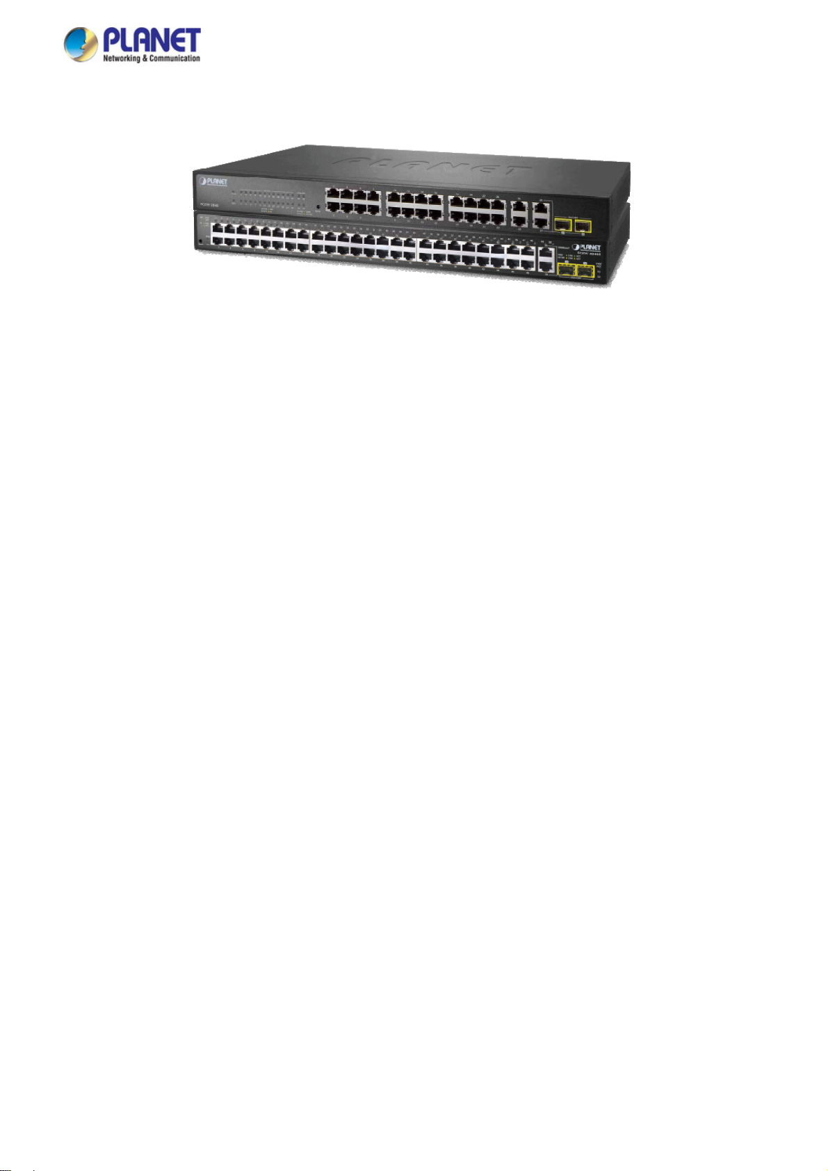
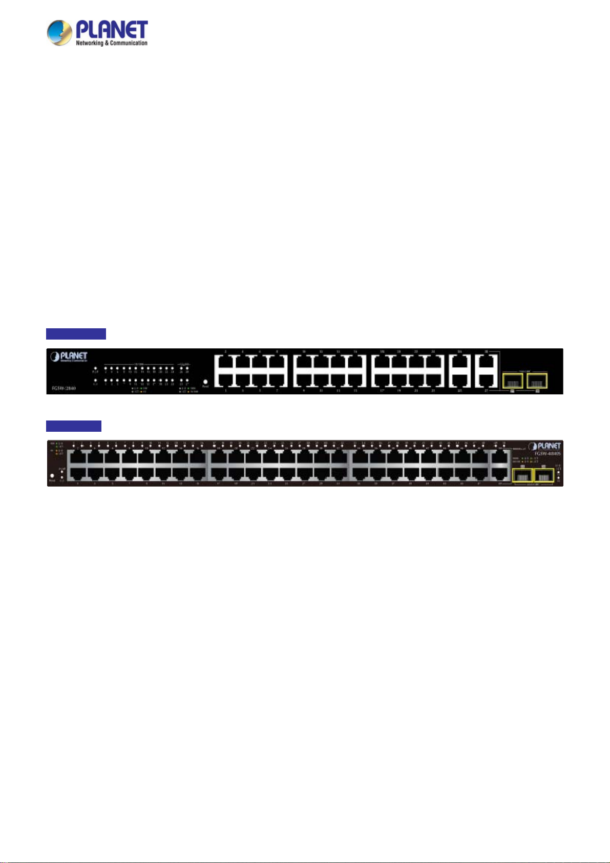
Thank you for purchasing PLANET 24 / 48-Port 10/100TX + 4-Port Gigabit Managed Switch, FGSW-2840/FGSW-4840S. The
descriptions of these two models are shown below:
FGSW-2840
FGSW-4840S
“Managed Switch” mentioned in this quick installation guide refers to the FGSW-2840 and FGSW-4840S.
24-Port 10/100TX + 4-Port Gigabit with 2 Combo 100/1000X SFP Managed Switch
48-Port 10/100TX + 2-Port Gigabit + 2-Port 1000X SFP Managed Switch
1.1 Package Contents
Open the box of the Managed Switch and carefully unpack it. The box should contain the following items:
The FGSW-2840 or FGSW-4840S x 1 (With SFP Dust Cap x 2)
Quick Installation Guide x 1
Power Cord x 1
Rubber Feet x 4
Two 19” Rack-mounting Brackets Kit x 1
If any of these are missing or damaged, please contact your dealer immediately; if possible, retain the carton including the
original packing material, and use them again to repack the product in case there is a need to return it to us for repair.
9
Page 10
User’s Manual of FGSW-2840 / FGSW-4840S
1.2 Product Description
High-Density, Full-Functioned, Layer 2 Managed Switch for Enterprise and Campus Networking
The FGSW-2840 and FGSW-4840S is a 24/48-Port 10/100Mbps Fast Ethernet Switch with 2/4-Port Gigabit and 2-Port Gigabit
SFP interfaces, which comes with a high-performance switch architecture, capable of providing non-blocking 12.8Gbps
(FGSW-2840) / 17.6Gbps (FGSW-4840S) switch fabric and wire-speed throughput at 9.5Mpps (FGSW-2840) / 13Mpps
(FGSW-4840S). Its four built-in GbE uplink ports also offer incredible extensibility, flexibility and connectivity to the core switch
or servers. The powerful features of QoS and network security offered by the FGSW-2840 / FGSW-4840S enable the switch to
perform effective data traffic control for ISP and enterprise VoIP, video streaming and multicast applications. It is ideal for the
remote access layer of campus or enterprise networks and the aggregation layer of IP metropolitan networks.
Robust Layer 2 Feature
The FGSW-2840 / FGSW-4840S can be programmed for advanced switch management functions such as port mirror, port
security, port isolation and loopback detection. It also features the dynamic port link aggregation (Static Trunk and LACP),
802.1Q VLAN, Rapid Spanning Tree protocol (RSTP) and Multiple Spanning Tree protocol (MSTP), Static / Dynamic /
Filtering MAC address, IGMP Snooping, Multicast IP and Multicast Filter and DHCP filtering. Via aggregation of supporting
ports, the FGSW-2840 / FGSW-4840S allow the operation of a high-speed trunk to combine with multiple ports. It enables a
maximum of up to 6 groups of 4 ports for trunk and supports fail-over as well.
Enhanced Security
The FGSW-2840 / FGSW-4840S offer comprehensive Layer 2 to Layer 4 Access Control List (ACL) for enforcing security to
the edge. It can be used to restrict network access by denying packets based on source and destination IP address.
Efficient Traffic Control
The FGSW-2840 / FGSW-4840S is loaded with robust QoS features and powerful traffic management to enhance services to
business-class data, voice, and video solutions. The functionality includes broadcast / multicast / unicast storm control, per
port bandwidth control, 802.1p / CoS / IP DSCP QoS priority and remarking. It guarantees the best performance at VoIP and
video stream transmission, and empowers the enterprises to take full advantages of the limited network resources.
Enhanced and Secure Management
For efficient management, the FGSW-2840 / FGSW-4840S are equipped with Web, Telnet and SNMP management interfaces.
With the built-in Web-based management interface, the FGSW-2840 / FGSW-4840S offer an easy-to-use, platform-independent
management and configuration facility. By supporting the standard Simple Network Management Protocol (SNMP), the switch
can be managed via any standard management software. For text-based management, the switch can be accessed via Telnet .
10
Page 11

User’s Manual of FGSW-2840 / FGSW-4840S
Moreover, the FGSW-2840 / FGSW-4840S offers secure remote management by supporting HTTPS and SNMPv3 connections
which encrypt the packet content at each session.
Flexible Extension Solution
The two mini-GBIC slots built in the FGSW-2840 / FGSW-4840S are compatible with the 1000Base-SX/LX SFP (Small
Form-factor Pluggable) fiber transceiver to uplink to the backbone switch and monitoring center in long distance. The distance
can be extended from 550 meters (multi-mode fiber) to 10/20/30/40/50/60/70/120 kilometers (single-mode fiber or WDM fiber).
They are well suited for applications within the enterprise data centers and distributions, the two mini-GBIC slots built in the
FGSW-2840 also compatible with 100Base-FX SFP fiber transceiver.
1.3 How to Use This Manual
This User Manual is structured as follows:
Section 2 INSTALLATION
The section explains the functions of the Managed Switch and how to physically install the Managed Switch.
Section 3 SWITCH MANAGEMENT
The section contains the information about the software function of the Managed Switch.
Section 4 WEB CONFIGURATION
The section explains how to manage the Managed Switch by Web interface.
Section 5 COMMAND LINE INTERFACE
The section describes how to use the Command Line interface (CLI).
Section 6 COMMAND LINE MODE
The section explains how to manage the Managed Switch by Command Line interface.
Section 7 SWITCH OPERATION
The chapter explains how to do the switch operation of the Managed Switch.
Section 8 TROUBLESHOOTING
The chapter explains how to troubleshoot the Managed Switch.
Appendix A
The section contains cable information of the Managed Switch.
11
Page 12

User’s Manual of FGSW-2840 / FGSW-4840S
1.4 Product Features
Physical Port (FGSW-2840)
■ 24-port 10/100Base-TX Fast Ethernet RJ45 copper, auto MDI / MDIX
■ 4-port 10/100/1000Base-T Gigabit Ethernet RJ45 copper, auto MDI / MDIX
■ 2 Combo 100/1000Base-X mini-GBIC/SFP slots (Share with Port 27/28)
■ Reset button for system factory default
Physical Port (FGSW-4840S)
■ 48-port 10/100Base-TX Fast Ethernet RJ45 copper, auto MDI / MDIX
■ 2-port 10/100/1000Base-T Gigabit Ethernet RJ45 copper, auto MDI / MDIX
■ 2 1000Base-X mini-GBIC/SFP slots
■ Reset button for system factory default
Layer 2 Features
■ Prevents packet loss with back pressure (half-duplex) and IEEE 802.3x pause frame flow control (full-duplex)
■ High-performance Store and Forward architecture, and runt/CRC filtering eliminates erroneous packets to optimize
the network bandwidth
■ Supports VLAN
- IEEE 802.1Q tagged VLAN, up to 512VLAN groups, out of 4094 VLAN IDs
- Management VLAN
■ Supports Spanning Tree Protocol
- STP (Spanning Tree Protocol)
- RSTP (Rapid Spanning Tree Protocol)
- MSTP (Multiple Spanning Tree Protocol)
- Loop Guard, Root Guard, TC, BPDU Guard, STP BPDU Guard, BPDU Filtering
■ Supports Link Aggregation
IEEE 802.3ad Link Aggregation Control Protocol (LACP)
Cisco ether-channel (Static Trunk)
Maximum 6 trunk groups, up to 4 ports per trunk group
■ Provides port mirror (many-to-1)
Quality of Service
■ Ingress / Egress Rate Limit per port bandwidth control
■ Storm Control support
Broadcast / Unknown Unicast / Unknown Multicast
■ Traffic classification
- IEEE 802.1p CoS
- DSCP / ToS priority
■ Strict priority, Weighted Round Robin (WRR) and Equal CoS policies
■ Voice VLAN
12
Page 13

Multicast
■ IGMP Snooping v1, v2 and v3
■ Multicast IP Table / Static Multicast IP
■ Multicast Filter
Security
■ L2 / L3 / L4 Access Control List
■ MAC Security
Static MAC
MAC Filtering
■ Port Security for Source MAC address entries filtering
■ Port Isolation, loopback detection
■ DHCP Filtering
Management
■ Switch Management Interface
- Web switch management
- Telnet Command Line Interface
- SNMP v1, v2c and v3
- SSL v2, v3 / SSH v1,v2 secure access
- IP / MAC / Port-based Web access control
■ Static, DHCP and BooTP for IP address assignment
User’s Manual of FGSW-2840 / FGSW-4840S
■ System Maintenance
- Firmware upload / download via HTTP
- Configuration upload / download through HTTP
- Hardware reset button for system reset to factory default
- System CPU / Memory status monitor
■ System Time Setting
- Manual Setting
- Network Time Protocol
- PC clock synchronization
■ Daylight Saving Time Setting
■ SNMP trap for interface Link Up and Link Down notification
■ System Local Log / remote log / backup log
■ Four RMON groups (history, statistics, alarms and events)
■ Virtual Cable Test / Loop Back Test
13
Page 14
User’s Manual of FGSW-2840 / FGSW-4840S
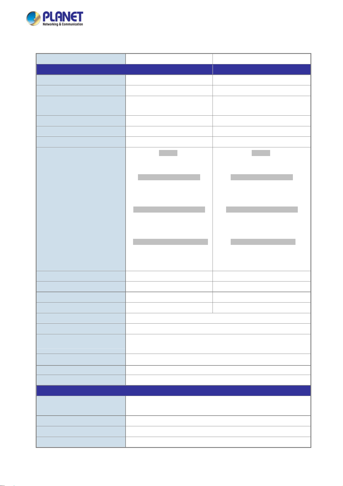
1.5 Product Specifications
Product FGSW-2840 FGSW-4840S
Hardware Specifications
Hardware Version 1 3
10/100TX Copper Ports (MDI/MDIX) 24 48
10/100/1000T Copper Ports
(MDI/MDIX)
SFP/mini-GBIC Slots 2 100/1000Base-X SFP interfaces 2 1000Base-X SFP interfaces
Switch Fabric 12.8Gbps / non-blocking 17.6Gbps / non-blocking
Switch Throughput@64 bytes 9.5Mpps @64 bytes 13Mpps @64 bytes
10/100TX RJ45 Interfaces
(Port 1 to Port 24):
100 LNK / ACT (Green)
10 LNK/ACT (Orange)
LED
10/100/1000T RJ45 Interfaces
(Port 25 to Port 28):
1000 LNK / ACT (Green)
10/100 LNK/ACT (Orange)
100/1000Mbps SFP Interfaces
(Share with Port 27 to Port 28):
1000 LNK / ACT (Green)
100 LNK/ACT (Orange)
4 2
System:
Power (Green)
SYS (Green)
10/100TX RJ45 Interfaces
10/100/1000T RJ45 Interfaces
1000 LNK / ACT (Green)
10/100 LNK/ACT (Orange)
1000Mbps SFP Interfaces
1000 LNK / ACT (Green)
System:
Power (Green)
SYS (Green)
(Port 1 to Port 48):
100 LNK / ACT (Green)
10 LNK/ACT (Orange)
(Port 49 to Port 50):
(Port 51 to Port 52):
Power Requirements 100~240V AC, 50/60Hz, 0.6A 100~240V AC, 50/60Hz, 0.4A
Power Consumption / Dissipation Max 12.8 watts / 43 BTU Max.17.3 watts / 59BTU
Dimensions (W x D x H) 440 x 180 x 44mm (1U height) 440 x 180 x 44mm (1U height)
Weight 1.9kg 2.5kg
Switch Architecture Store-and-Forward
MAC Address Table 8K entries
Flow Control
Maximum Transmit Unit
Reset Button > 5 sec: Factory default
Enclosure Metal
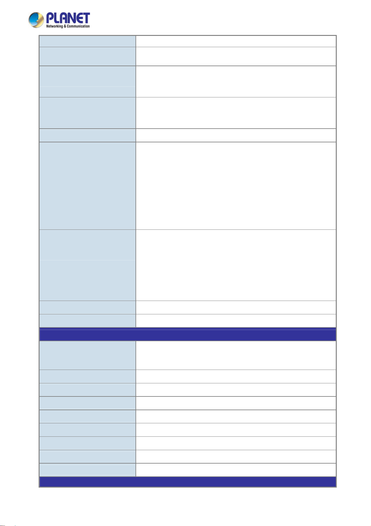
Layer 2 Functions
Port Mirroring
Port Security up to 64 MAC Address per port
Port Isolation Support
Loopback Detection Support
IEEE 802.3x pause frame for full-duplex
Back pressure for half-duplex
6bytes
921
TX / RX
Many-to-1 monitor
14
Page 15
User’s Manual of FGSW-2840 / FGSW-4840S
Link Aggregation IEEE 802.3ad LACP and static trunk supports 6 groups of 4-port trunk.
VLAN
Spanning Tree Protocol
Multicast
802.1Q tagged-based VLAN, up to 512 VLAN groups, out of 4094 VLAN IDs
Management VLAN
IEEE 802.1D STP
IEEE 802.1w RSTP
IEEE 802.1s MSTP
IGMP (v1/v2/v3) Snooping
Multicast IP
Multicast Filter
Access Control List
QoS
Security
Virtual Cable Test
L2 / L3 / L4 Access Control List
4 Priority Queues
Traffic classification:
- IEEE 802.1p CoS
- DSCP / ToS priority
Strict priority, Weighted Round Robin (WRR) and Equal CoS policies
Ingress / Egress Rate Limit per port bandwidth control
Storm Control support:
- Broadcast / Unknown Unicast / Unknown Multicast
Voice VLAN
MAC Security:
- Static MAC
- Dynamic MAC address
- MAC Filtering
Loop Guard, Root Guard, TC, BPDU Guard, STP BPDU Guard, BPDU
Filtering,
DHCP Filtering
Support
Loopback Test
Management Functions
Basic Management Interfaces
Secure Management Interfaces
Web Access Control
System IP Address Assign ment
System Log
System Time Setting
Daylight Saving Time
SNMP RMON
SNMP Trap
Standards Conformance
Support
Web browser / Telnet / SNMP v1, v2c, v3 / SSL v2, v3 / SSH v1,v2
Firmware upgrade by HTTP protocol through Ethernet network
Configuration Backup / Restore by HTTP protocol through Ethernet network
HTTPs, SNMP v3
IP / MAC / Port-based Web access control
Static, DHCP and BooTP
System local log / remote log / backup log
Manual Setting, Network Time Protocol, PC clock synchronization
Support
RFC 2819 RMON (1, 2, 3, 9)
Interface Link
Up and Link Down notification
15
Page 16

User’s Manual of FGSW-2840 / FGSW-4840S
Regulation Compliance
Standards Compliance
Environment
Operating
Storage
FCC Part 15 Class A, CE
IEEE 802.3 10Base-T
IEEE 802.3u 100Base-TX / 100Base-FX
IEEE 802.3z Gigabit SX/LX
IEEE 802.3ab Gigabit 1000Base-T
IEEE 802.3x Flow Control and Back pressure
IEEE 802.3ad Port Trunk with LACP
IEEE 802.1D Spanning Tree protocol
IEEE 802.1w Rapid Spanning Tree protocol
IEEE 802.1s Multiple Spanning Tree protocol
IEEE 802.1p Class of Service
IEEE 802.1Q VLAN Tagging
RFC 768 UDP
RFC 791 IP
RFC 792 ICMP
RFC 2068 HTTP
RFC 1112 IGMP version 1
RFC 2236 IGMP version 2
RFC 3376 IGMP version 3
Temperature: 0 ~ 50 degrees C
Relative Humidity: 5 ~ 95% (non-condensing)
Temperature: -10 ~ 70 degrees C
Relative Humidity: 5 ~ 95% (non-condensing)
16
Page 17
User’s Manual of FGSW-2840 / FGSW-4840S
2. INSTALLATION
This section describes the hardware features and installation of the Managed Switch on the desktop or rack mount. For easier
management and control of the Managed Switch, familiarize yourself with its display indicators, and ports. Front panel
illustrations in this chapter display the unit LED indicators. Before connecting any network device to the Managed Switch, please
read this chapter completely.
2.1 Hardware Description
2.1.1 Switch Front Panel
The front panel provides a simple interface monitoring the Managed Switch. Figure 2-1-1 & 2-1-2 shows the front panel of the
Managed Switch.
Front Panel
Figure 2-1-1: FGSW-2840 Front Panel
Front Panel
Figure 2-1-2: FGSW-4840S Front Panel
■ Fast Ethernet TP Interface
10/100Base-TX Copper, RJ-45 Twist-Pair: Up to 100 meters.
■ Gigabit TP Interface
10/100/1000Base-T Copper, RJ-45 Twist-Pair: Up to 100 meters.
■ 1000Base-X SFP Slots (FGSW-4840S)
Each of the SFP (Small Form-factor Pluggable) slot supports Dual-speed, 1000Base-SX / LX.
- For 1000Base-SX/LX SFP transceiver module: From 550 meters (Multi-mode fiber), up to 10/20/30/40/50/60/70/120
kilometers (Single-mode fiber).
■ 100/1000Base-X SFP Slots (FGSW-2840)
Each of the SFP (Small Form-factor Pluggable) slot supports Dual-speed, 1000Base-SX / LX or 100Base-FX.
- For 1000Base-SX/LX SFP transceiver module: From 550 meters (Multi-mode fiber), up to 10/20/30/40/50/60/70/120
kilometers (Single-mode fiber).
- For 100Base-FX SFP transceiver module: From 2 kilometers (Multi-mode fiber), up to 20/40/60 kilometers
(Single-mode fiber).
17
Page 18
User’s Manual of FGSW-2840 / FGSW-4840S
■ Reset Button
At front panel of Managed Switch, the reset button is designed for reboot the Managed Switch without turn off and on the
power. The following is the summary table of Reset button function:
Reset Button Pressed and Released Function
Reset the Managed Switch to Factory Default configuration.
The Managed Switch will then reboot and load the default
settings as below:
> 5 seconds: Factory Default
。 Default Username: admin
。 Default Password: admin
。 Default IP address: 192.168.0.100
。 Subnet mask: 255.255.255.0
。 Default Gateway: 192.168.0.254
2.1.2 LED Indications
The front panel LEDs indicates instant status of port links, data activity, system power and system CPU status; helps monitor
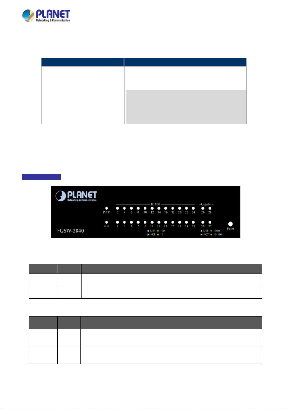
and troubleshoot when needed. Figure 2-1-3 & Figure 2-1-4 shows the LED indications of the Managed Switch.
LED Indication
Figure 2-1-3: FGSW-2840 LED Panel
■ FGSW-2840 LED Definition
System
LED Color Function
PWR Green
SYS Green
Lights to indicate that the Switch has power.
Lights and blinking to indicate the CPU is working.
10/100Base-TX In terfaces (Port 1 to port 24)
LED
100
LNK/ACT
10
LNK/ACT
Color Function
Lights: To indicate the link through that port is successfully established at 100Mbps.
Green
Orange
Blink: To indicate that the Switch is actively sending or receiving data over that port.
Lights:
Blink:
To indicate the link through that port is successfully established at 10Mbps.
To indicate that the Switch is actively sending or receiving data over that port.
18
Page 19
■ 10/100/1000Base-T Interfaces (Port 25 to port 28)
User’s Manual of FGSW-2840 / FGSW-4840S
LED
1000
LNK/ACT
10/100
LNK/ACT
■ 1000Base-X SFP Interfaces (Share with Port 27 to port 28)
LED
1000
LNK/ACT
100
LNK/ACT
Color Function
Lights: To indicate the link through that port is successfully established at 1000Mbps.
Green
Orange
Color Function
Green
Orange
Blink: To indicate that the Switch is actively sending or receiving data over that port.
Lights:
Blink:
Lights: To indicate the link through that port is successfully established at 1000Mbps.
Blink: To indicate that the Switch is actively sending or receiving data over that port.
Lights:
Blink:
To indicate the link through that port is successfully established at 10Mbps or 100Mbps.
To indicate that the Switch is actively sending or receiving data over that port.
To indicate the link through that port is successfully established at 100Mbps.
To indicate that the Switch is actively sending or receiving data over that port.
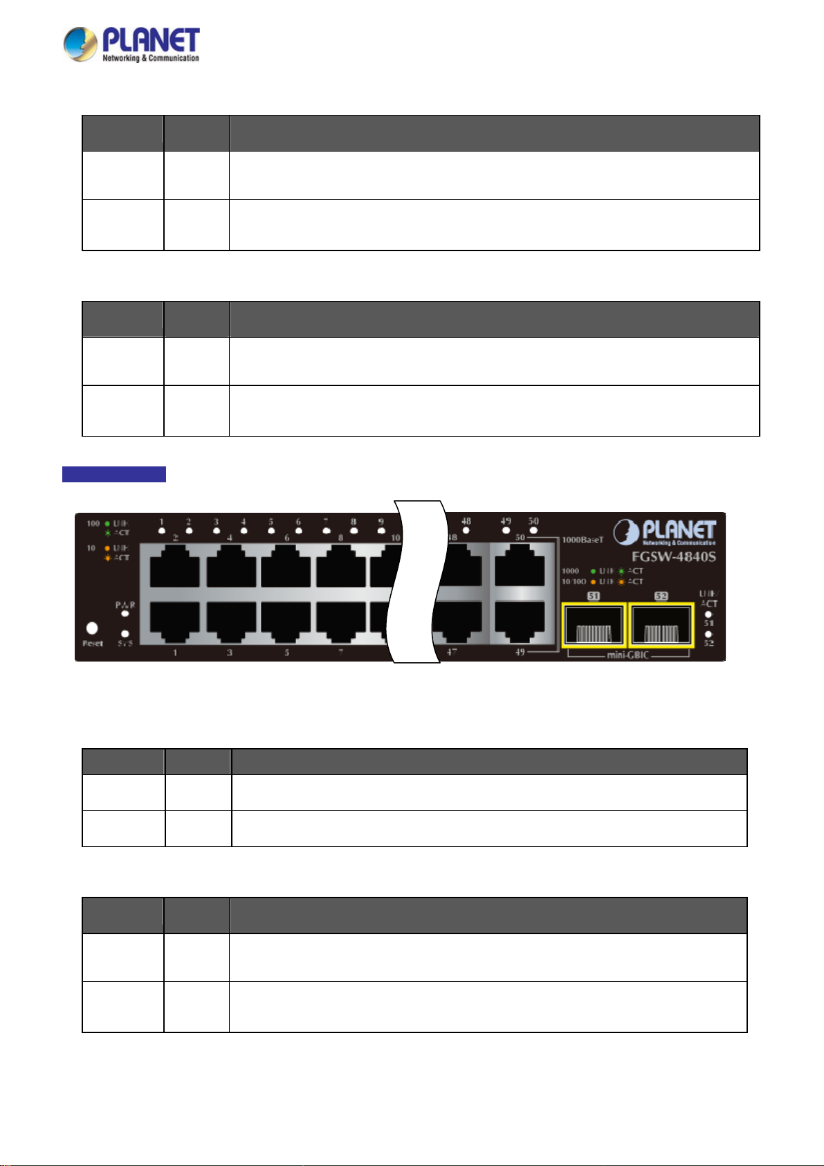
LED Indication
Figure 2-1-4: FGSW-4840S LED Panel
■ FGSW-4840S LED Definition
System
LED Color Function
PWR Green
SYS Green
10/100Base-TX In terfaces (Port 1 to port 48)
LED
100
LNK/ACT
10
LNK/ACT
Color Function
Green
Orange
Lights to indicate that the Switch has power.
Lights and blinking to indicate the CPU is working.
Lights: To indicate the link through that port is successfully established at 100Mbps.
Blink: To indicate that the Switch is actively sending or receiving data over that port.
Lights:
Blink:
To indicate the link through that port is successfully established at 10Mbps.
To indicate that the Switch is actively sending or receiving data over that port.
19
Page 20
■ 10/100/1000Base-T Interfaces (Port 49 to port 50)
User’s Manual of FGSW-2840 / FGSW-4840S
LED
1000
LNK/ACT
10/100
LNK/ACT
■ 1000Base-X SFP Interfaces (Port 51 to port 52)
LED
LNK/ACT
Color Function
Lights: To indicate the link through that port is successfully established at 1000Mbps.
Green
Orange
Color Function
Green
Blink: To indicate that the Switch is actively sending or receiving data over that port.
Lights:
Blink:
Lights: To indicate the link through that port is successfully established at 1000Mbps.
Blink: To indicate that the Switch is actively sending or receiving data over that port.
To indicate the link through that port is successfully established at 10Mbps or 100Mbps.
To indicate that the Switch is actively sending or receiving data over that port.
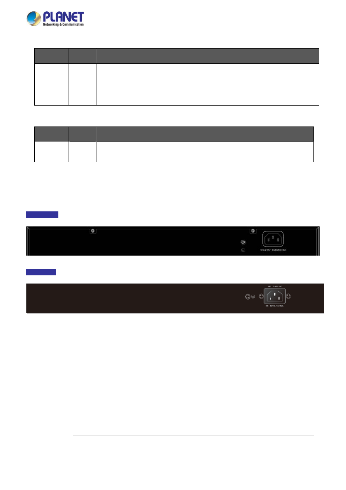
2.1.3 Switch Rear Panel
The rear panel of the Managed Switch indicates an AC inlet power socket, which accepts input power from 100 to 240V AC,
50-60Hz. Figure 2-1-5 & Figure 2-1-6 shows the rear panel of this Managed Switch.
Rear Panel
Figure 2-1-5: Rear Panel of FGSW-2840
Rear Panel
Figure 2-1-6: Rear Panel of FGSW-4840S
■ AC Power Receptacle
For compatibility with electric service in most areas of the world, the Managed Switch’s power supply automatically adjusts
to line power in the range of 100-240V AC and 50/60Hz.
Plug the female end of the power cord firmly into the receptalbe on the rear panel of the Managed Switch. Plug the other
end of the power cord into an electric service outlet and the power will be ready.
The device is a power-required device, which means it will not work till it is powered. If your networks
Power Notice:
should be active all the time, please consider using UPS (Uninterrupted Power Supply) for your device.
It will prevent you from network data loss or network downtime.
20
Page 21
User’s Manual of FGSW-2840 / FGSW-4840S
wer Notice:
Po
In some areas, installing a surge suppression device may also help to protect your Managed Switch
from being damaged by unregulated surge or current to the Managed Switch or the power adapter.
2.2 Installing the Switch
This section describes how to install your Managed Switch and make connections to the Managed Switch. Please read the
following topics and perform the procedures in the order being presented. To install your Managed Switch on a desktop or shelf,
simply complete the following steps.
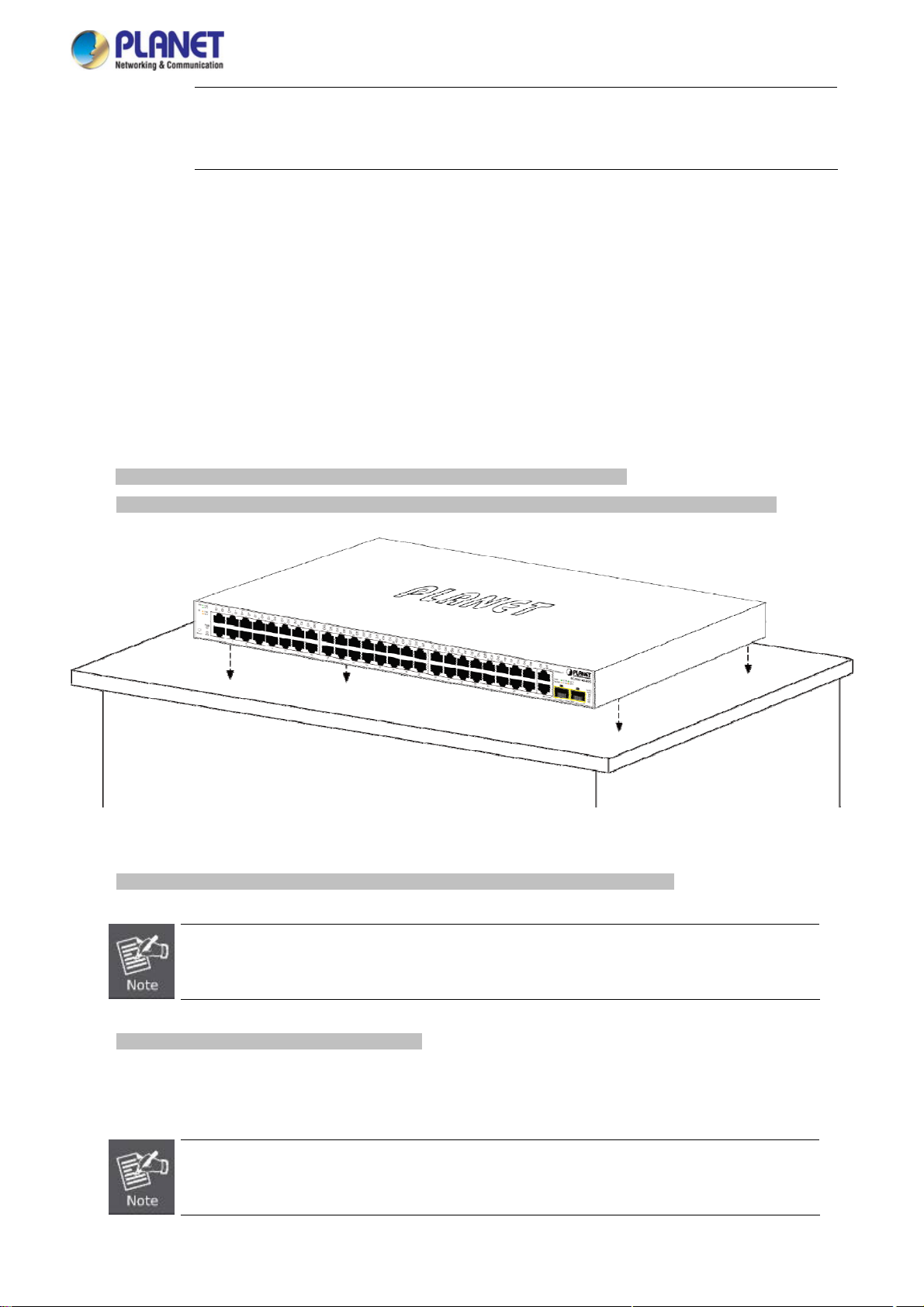
2.2.1 Desktop Installation
To install the Managed Switch on desktop or shelf, please follow these steps:
Step1: Attach the rubber feet to the recessed areas on the bottom of the Managed Switch.
Step2: Place the Managed Switch on the desktop or the shelf near an AC power source, as shown in Figure 2-1-7.
Figure 2-1-7: Place the Managed Switch on the desktop
Step3: Keep enough ventilation space between the Managed Switch and the surrounding objects.
When choosing a location, please keep in mind the environmental restrictions discussed in Chapter 1,
Section 4, and specifications.
Step4: Connect the Managed Switch to network devices.
Connect one end of a standard network cable to the RJ-45 ports on the front of the Managed Switch.
Connect the other end of the cable to the network devices such as printer server, workstation or router.
Connection to the Managed Switch requires UTP Category 5 network cabling with RJ-45 tips. For more
information, please see the Cabling Specification in Appendix A.
21
Page 22
User’s Manual of FGSW-2840 / FGSW-4840S
Step5: Supply power to the Managed Switch.
Connect one end of the power cable to the Managed Switch.
Connect the power plug of the power cable to a standard wall outlet.
When the Managed Switch receives power, the Power LED should remain solid Green.
2.2.2 Rack Mounting
To install the Managed Switch in a 19-inch standard rack, please follow the instructions described below.
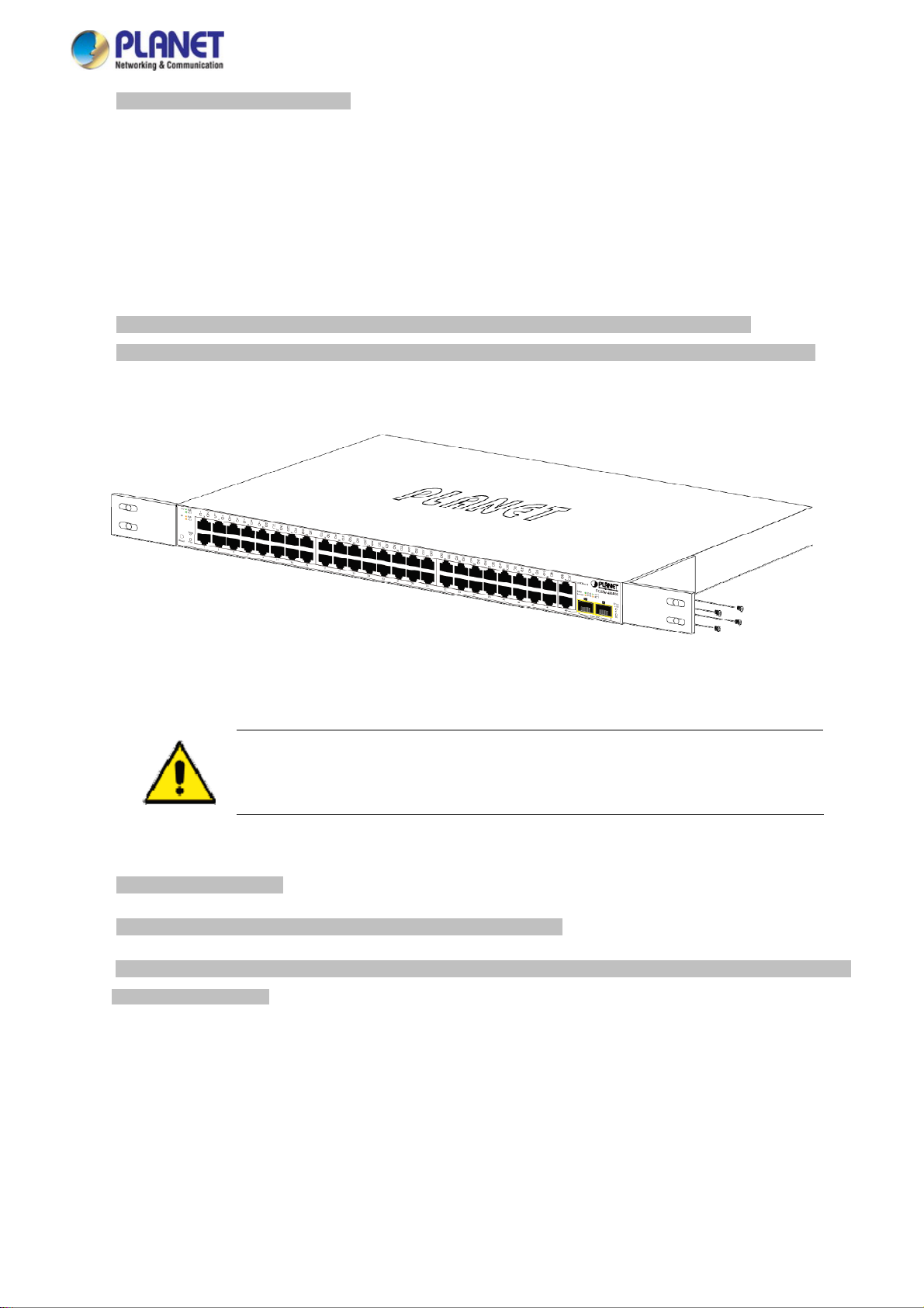
Step1: Place the Managed Switch on a hard flat surface, with the front panel positioned towards the front side.
Step2: Attach the rack-mount bracket to each side of the Managed Switch with supplied screws attached to the package.
Figure 2-1-8 shows how to attach brackets to one side of the Managed Switch.
Figure 2-1-8: Attach Brackets to the Managed Switch
You must use the screws supplied with the mounting brackets. Damage caused to the parts by
using incorrect screws would invalidate the warranty.
Step3: Secure the brackets tightly.
Step4: Follow the same steps to attach the second bracket to the opposite side.
Step5: After the brackets are attached to the Managed Switch, use suitable screws to securely attach the brackets to the rack,
as shown in Figure 2-1-9.
22
Page 23

User’s Manual of FGSW-2840 / FGSW-4840S
Figure 2-1-9: Mounting Managed Switch in a Rack
Step6: Proceeds with Steps 4 and 5 of session 2.2.1 Desktop Installation to connect the network cabling and supply power to
the Managed Switch.
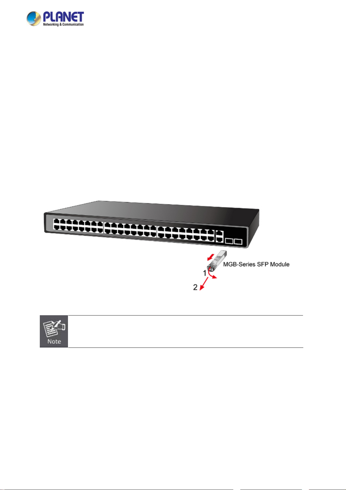
2.2.3 Installing the SFP transceiver
The sections describe how to insert an SFP transceiver into an SFP slot.
The SFP transceivers are hot-pluggable and hot-swappable. You can plug in and out the transceiver to/from any SFP port
without having to power down the Managed Switch, as the Figure 2-1-10 shows.
Figure 2-1-10: Plug In the SFP Transceiver
23
Page 24

User’s Manual of FGSW-2840 / FGSW-4840S
Approv
PLANET Managed Switch supports both Single mode and Multi-mode SFP transceiver. The following list of approved PLANET
SFP transceivers is correct at the time of publication:
ed PLANET SFP Transceivers
Gigabit SFP Transceiver Modules (FGSW-2840 / FGSW-4840S)
MGB-GT
MGB-SX
MGB-LX
MGB-L30
MGB-L50
MGB-L70
MGB-L120
MGB-LA10
MGB-LB10
MGB-LA20
MGB-LB20
MGB-LA40
SFP-Port 1000Base-T Module
SFP-Port 1000Base-SX mini-GBIC module
SFP-Port 1000Base-LX mini-GBIC module -10KM
SFP-Port 1000Base-LX mini-GBIC module -30KM
SFP-Port 1000Base-LX mini-GBIC module -50KM
SFP-Port 1000Base-LX mini-GBIC module -70KM
SFP-Port 1000Base-LX mini-GBIC module -120KM
SFP-Port 1000Base-LX (WDM,TX:1310nm) -10KM
SFP-Port 1000Base-LX (WDM,TX:1550nm) -10KM
SFP-Port 1000Base-LX (WDM,TX:1310nm) -20KM
SFP-Port 1000Base-LX (WDM,TX:1550nm) -20KM
SFP-Port 1000Base-LX (WDM,TX:1310nm) -40KM
MGB-LB40
SFP-Port 1000Base-LX (WDM,TX:1550nm) -40KM
Fast Ethernet SFP Transceiver Modules (FGSW-2840 only)
MFB-FX
MFB-F20
MFB-F40
MFB-F60
MFB-FA20
MFB-FB20
SFP-Port 100Base-FX Transceiver -2KM
SFP-Port 100Base-FX Transceiver -20KM
SFP-Port 100Base-FX Transceiver -40KM
SFP-Port 100Base-FX Transceiver -60KM
SFP-Port 100Base-BX Transceiver (WDM,TX:1310nm) -20KM
SFP-Port 100Base-BX Transceiver (WDM,TX:1550nm) -20KM
It is recommended to use PLANET SFP on the Managed Switch. If you insert an SFP transceiver
that is not supported, the Managed Switch will not recognize it.
In the installation steps below, this Manual uses Gigabit SFP transceiver as an example. However,
the steps for Fast Ethernet SFP transceiver are similar.
1. Before we connect Managed Switch to the other network device, we have to make sure both sides of the SFP
transceivers are with the same media type, for example: 1000Base-SX to 1000Base-SX, 1000Bas-LX to 1000Base-LX.
2. Check whether the fiber-optic cable type matches with the SFP transceiver requirement.
To connect to 1000Base-SX SFP transceiver, please use the multi-mode fiber cable with one side being the male
duplex LC connector type.
To connect to 1000Base-LX SFP transceiver, please use the single-mode fiber cable with one side being the male
24
Page 25
User’s Manual of FGSW-2840 / FGSW-4840S
duplex LC connector type.
Connect the Fiber Cable
1. Insert the duplex LC connector into the SFP transceiver.
2. Connect the other end of the cable to a device with SFP transceiver installed.
3. Check the LNK/ACT LED of the SFP slot on the front of the Managed Switch. Ensure that the SFP transceiver is operating
correctly.
4. Check the Link mode of the SFP port if the link fails. To function with some fiber-NICs or Media Converters, user has to set
the port Link mode to “1000 Force” or “100 Force”.
Remove the Transceiver Module
1. Make sure there is no network activity anymore.
2. Remove the Fiber-Optic Cable gently.
3. Lift up the lever of the MGB module and turn it to a horizontal position.
4. Pull out the module gently through the lever.
Figure 2-1-11: How to Pull Out the SFP Transceiver
Never pull out the module without lifting up the lever of the module and turning it to a horizontal
position. Directly pulling out the module could damage the module and the SFP module slot of the
Managed Switch.
25
Page 26

User’s Manual of FGSW-2840 / FGSW-4840S
3. SWITCH MANAGEMENT
This chapter explains the methods that you can use to configure management access to the Managed Switch. It describes the
types of management applications and the communication and management protocols that deliver data between your
management device (workstation or personal computer) and the system. It also contains information about port connection
options.
This chapter covers the following topics:
Requirements
Management Access Overview
Web Management Access
SNMP Access
3.1 Requirements
Workstations running Windows 2000/XP, 2003, Vista/7/8, 2008, MAC OS9 or later, Linux, UNIX or other platforms
are compatible with TCP/IP protocols.
Workstation is installed with Ethernet NIC (Network Interface Card)
Ethernet Port connection
Network cables -- Use standard network (UTP) cables with RJ45 connectors.
The above Workstation is installed with WEB Browser and JAVA runtime environment Plug-in
It is recommended to use Internet Explore 8.0 or above to access the Managed Switch. If the Web
interface of the Managed Switch is not accessible, please turn off the anti-virus software or firewall
and then try it again.
26
Page 27
User’s Manual of FGSW-2840 / FGSW-4840S
3.2 Management Access Overview
The Managed Switch gives you the flexibility to access and manage it using any or all of the following methods:
Web browser interface
An external SNMP-based network management application
The administration Web browser interface supports are embedded in the Managed Switch software and are available for
immediate use. Each of these management methods has their own advantages. Table 3-1 compares the three management
methods.
Method Advantages Disadvantages
Web Browser
SNMP Agent
Ideal for configuring the switch remotely
Compatible with all popular browsers
Can be accessed from any location
Most visually appealing
Communicates with switch functions at
the MIB level
Based on open standards
Table 3-1: Comparison of Management Methods
Security can be compromised (hackers need
only know the IP address and subnet mask)
May encounter lag times on poor connections
Requires SNMP manager software
Least visually appealing of all three methods
Some settings require calculations
Security can be compromised (hackers need
only know the community name)
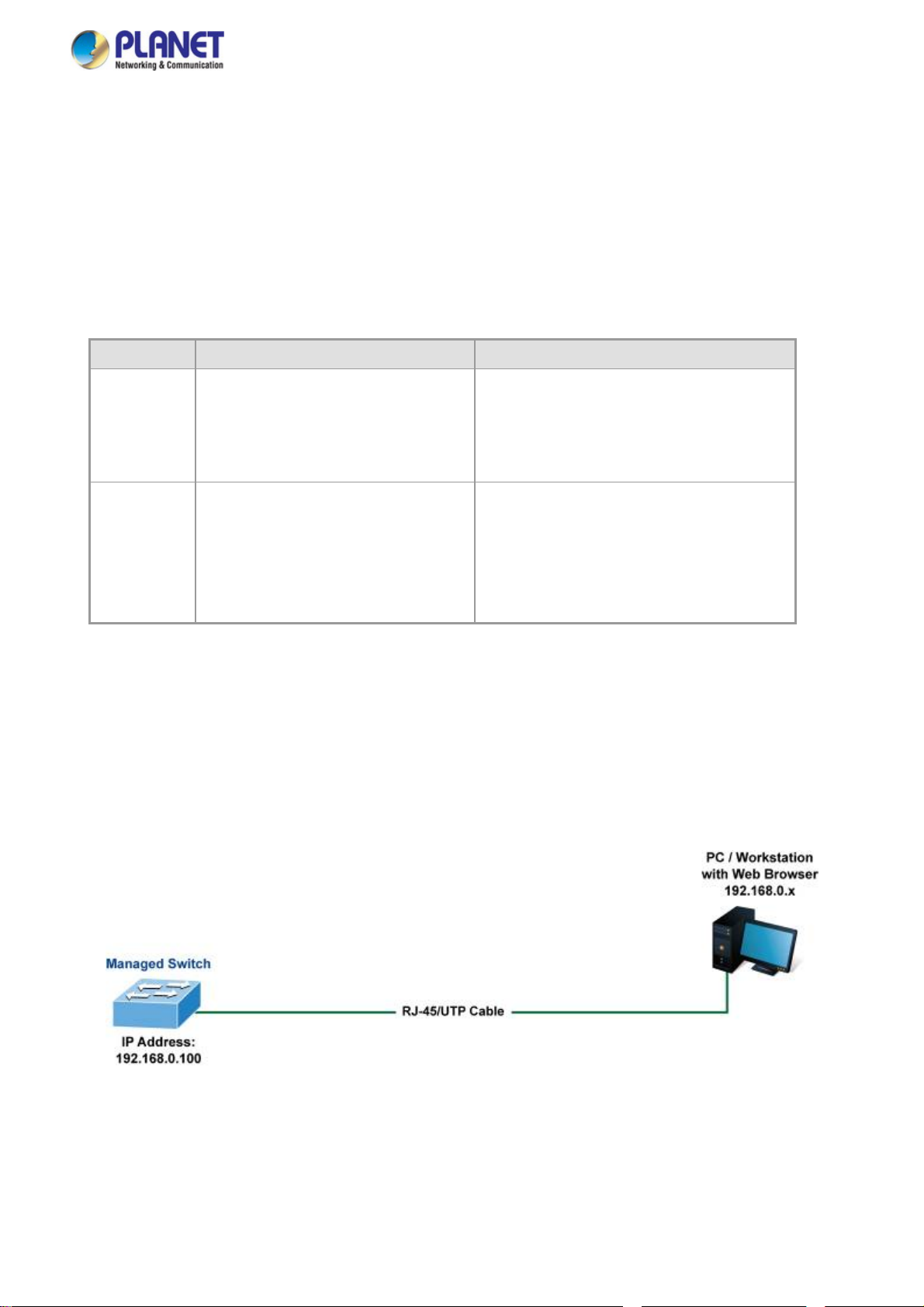
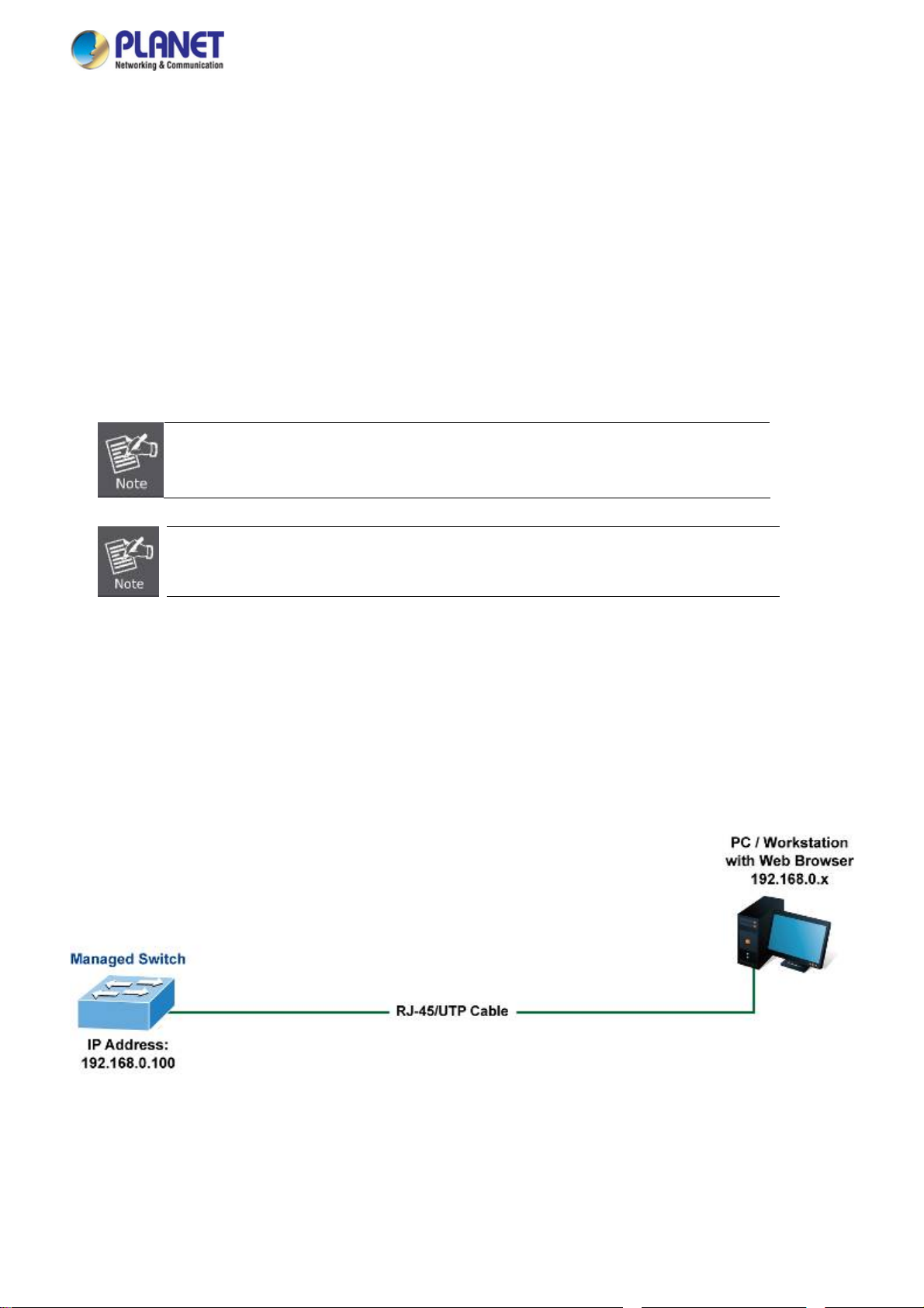
3.3 Web Management
The Managed Switch offers management features that allow users to manage the Managed Switch from anywhere on the
network through a standard browser such as Microsoft Internet Explorer. After you set up your IP address for the Managed
Switch, you can access the Managed Switch’s Web interface applications directly in your Web browser by entering the IP
address of the Managed Switch.
Figure 3-1: Web Management
You can then use your Web browser to list and manage the Managed Switch configuration parameters from one central location;
Web Management requires Microsoft Internet Explorer 8.0 or later, Google Chrome, Safari or Mozilla Firefox 1.5 or later.
27
Page 28
User’s Manual of FGSW-2840 / FGSW-4840S
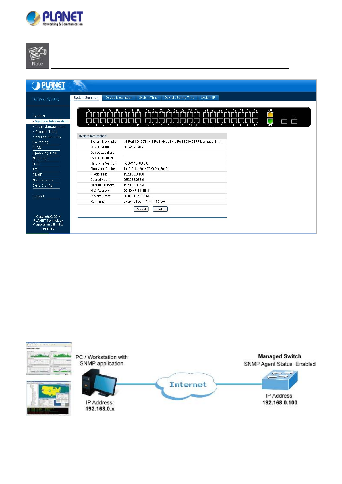
The following web screen based on FGSW-4840S, for FGSW-2840 the display will be the same
to FGSW-4840S.
Figure 3-2: Web Main Screen of Managed Switch
3.4 SNMP-Based Network Management
You can use an external SNMP-based application to configure and manage the Managed Switch, such as SNMPc Network
Manager, HP Openview Network Node Management (NNM) or What’s Up Gold. This management method requires the SNMP
agent on the switch and the SNMP Network Management Station to use the same community string. This management
method, in fact, uses two community strings: the get community string and the set community string. If the SNMP Network
management Station only knows the set community string, it can read and write to the MIBs. However, if it only knows the get
community string, it can only read MIBs. The default gets and sets community strings for the Managed Switch are public.
Figure 3-3: SNMP Management
28
Page 29
User’s Manual of FGSW-2840 / FGSW-4840S
4. WEB CONFIGURATION
This section introduces the configuration and functions of the Web-based management.
About Web-based Management
The Managed Switch offers management features that allow users to manage the Managed Switch from anywhere on the
network through a standard browser such as Microsoft Internet Explorer.
The Web-based Management supports Internet Explorer 8.0. It is based on Java Applets with an aim to reduce network
bandwidth consumption, enhance access speed and present an easy viewing screen.
By default, IE8.0 or later version does not allow Java Applets to open sockets. The user has to
explicitly modify the browser setting to enable Java Applets to use network ports.
The following web screen based on FGSW-4840S, for FGSW-2840 the display will be the same
to FGSW-4840S.
The Managed Switch can be configured through an Ethernet connection, making sure the manager PC must be set on the same
IP subnet address as the Managed Switch.
For example, the default IP address of the Managed Switch is 192.168.0.100, then the manager PC should be set at
192.168.0.x (where x is a number between 1 and 254, except 100), and the default subnet mask is 255.255.255.0.
If you have changed the default IP address of the Managed Switch to 192.168.1.1 with subnet mask 255.255.255.0 via web,
then the manager PC should be set at 192.168.1.x (where x is a number between 2 and 254) to do the relative configuration on
manager PC.
Figure 4-1-1: Web Management
Logging on the Managed Switch
1. Use Internet Explorer 8.0 or above Web browser. Enter the factory-default IP address to access the Web interface. The
factory-default IP Address as following:
29
Page 30

User’s Manual of FGSW-2840 / FGSW-4840S
http://192.168.0.100
2. When the following login screen appears, please enter the default username "admin" with password “admin” to login the
main screen of Managed Switch. The login screen in Figure 4-1-2 appears.
Figure 4-1-2: Login Screen
Default User name: admin
Default Password: admin
After entering the username and password, the main screen appears as Figure 4-1-3.
Figure 4-1-3: Web Main Screen of Managed Switch
30
Page 31

User’s Manual of FGSW-2840 / FGSW-4840S
Now, you can use the Web management interface to continue the switch management or manage the Managed Switch by Web
interface. The Switch Menu on the left of the web page let you access all the commands and statistics the Managed Switch
provides.
It is recommended to use Internet Explore 8.0 or above to access Managed Switch.
The changed IP address takes effect immediately after clicking on the Apply button. You need
to use the new IP address to access the Web interface.
For security reason, please change and memorize the new password after this first setup.
Only accept command in lowercase letter under web interface.
31
Page 32

User’s Manual of FGSW-2840 / FGSW-4840S
4.1 Main Web Page
The Managed Switch provides a Web-based browser interface for configuring and managing it. This interface allows you to
access the Managed Switch using the Web browser of your choice. This chapter describes how to use the Managed Switch’s
Web browser interface to configure and manage it.
Main Functions Menu
Main Screen Copper Port Link Status SFP Port Link Status
Figure 4-1-4: Web Main Page
Panel Display
The web agent displays an image of the Managed Switch’s ports. The Mode can be set to display different information for the
ports, including Link up or Link down. Clicking on the image of a port opens the Port Status page.
The port states are illustrated as follows:
State Down Link at 100M Link at 10M
10/100TX RJ-45 Ports
State Down Link at 1000M Link at 10/100M
10/100/1000TRJ-45 Ports
State Down Link at 1000M
Link at 100M
(FGSW-2840 only)
SFP Ports
32
Page 33

User’s Manual of FGSW-2840 / FGSW-4840S
Main Menu
Using the onboard web agent, you can define system parameters, manage and control the Managed Switch and all its ports, or
monitor network conditions. Via the Web-Management, the administrator can set up the Managed Switch by selecting the
functions listed in the Main Function. The screen in Figure 4-1-5 appears.
Figure 4-1-5: Managed Switch Main Functions Menu
33
Page 34

User’s Manual of FGSW-2840 / FGSW-4840S
4.2 System
Use the System menu items to display and configure basic administrative details of the Managed Switch. Under System, the
following topics are provided to configure and view the system information. This section has the following items:
■ System Information The switch system information is provided here.
■ User Management Configure the switch management interface access authority on this page.
■ System Tools
■ Access Security Configure system access security function on this page.
The system tools provided here to configure related options.
4.2.1 System Information
The System Info page provides basic properties configuration that can be implemented on System Summary, Device
Description, System Time, Daylight Saving Time and System IP pages. The screen in Figure 4-2-1 appears.
The page includes the following fields:
Object Description
System Summary
Device Description
System Time
Daylight Saving Time
System IP
Figure 4-2-1: System Information Page Screenshot
Vi
ew the port connection status and the system information on this page.
nfigure the description of the switch, including device name, device location and
Co
system contact on this page.
onfigure the system time and the settings here will be used for other time-based
C
functions on this page.
Configure the Daylight Saving Time of the switch on this page.
Configure the system IP of the switch on this page.
34
Page 35

User’s Manual of FGSW-2840 / FGSW-4840S
4.2.1.1 System Summary
The port status diagram shows the working status of 10/100Mbps RJ45 ports, 10/100/1000Mbps RJ45 ports and 2 SFP ports of
the Managed Switch, the System Summary includes the Managed Switch system information and the screen in Figure 4-2-2
appears.
The page includes the following fields:
Object Description
System Description
Device Name
Device Location
System Contact
Hardware Version
Firmware Version
IP Address
Subnet Mask
Default Gateway
MAC Address
System Time
Figure 4-2-2: System Summary Page Screenshot
Displ
ays the current system description information.
Displ
ays the current system name information.
Displ
ays the current device location information.
Displ
ays the current system contact information.
Displ
ays the current hardware version information.
Displ
ays the current firmware version information.
Displ
ays the current IP address information.
Displ
ays the current IP subnet mask address information.
Displ
ays the current IP default gateway information.
Displ
ays the current MAC address information.
Displ
ays the current system time information.
Buttons
Run Time
: Click to refresh the current web page.
: Click to display the help web page.
Displ
ays the current system operation time information.
35
Page 36

User’s Manual of FGSW-2840 / FGSW-4840S
4.2.1.2 Device Description
This page allows configuring the description of the Managed Switch, including device name, device location and system contact.
After setup is completed, please press “Apply” button to take effect, and the screen in Figure 4-2-3 appears.
Figure 4-2-3: Device Description Page Screenshot
The page includes the following fields:
Object Description
Device Name
Device Location
System Contact
Button
: Click to apply changes.
The name identifying the Managed Switch.
Maximum length: 32 characters.
The device location information of the Managed Switch.
Maximum length: 32 characters.
The system contact information of the Managed Switch.
Maximum length: 32 characters.
36
Page 37

User’s Manual of FGSW-2840 / FGSW-4840S
4.2.1.3 System Time
This page allows configuring system time and the settings here will be used for other time-based functions. After setup is
completed, please press “Apply” button to take effect, and the screen in Figure 4-2-4 appears.
The page includes the following fields:
Object Description
Time Information
Time Config
Figure 4-2-4: System Time Page Screenshot
Current System Date:
Displays the current date and time of the Managed Switch.
Current Time Source:
Displays the current time source of the Managed Switch.
To set time from the following methods.
Manual - When this option is selected, you can set the date and time manually.
Get Time from NTP Server - When this option is selected, you can configure
the time zone and the IP Address for the NTP Server. The Managed Switch will
get time automatically if it is connected to a NTP Server.
Time Zone: Select your local time.
Primary/Secondary NTP Server: Enter the IP Address for the NTP
Server.
Update Rate: Specify the rate of fetching time from NTP server.
Synchronize with PC Clock - When this option is selected, the administrator
PC clock is utilized.
37
Page 38

The system time will be restored to the default when the Managed Switch is restarted and you
need to reconfigure the system of the Managed Switch.
When Get Time from NTP Server is selected and no time server is configured, the Managed
Switch will get time from the time server of the Internet if it has connected to the Internet.
Buttons
: Click to apply changes.
: Click to refresh current web page.
: Click to display help web page.
4.2.1.4 Daylight Saving Time
The Daylight Saving Time Configuration screenin Figure 4-2-5 appears.
User’s Manual of FGSW-2840 / FGSW-4840S
The page includes the following fields:
Object Description
DST Status
Predefined Mode
Enable or disable the DST.
Select a predefined DST configuration.
USA: Second Sunday in March, 02:00 ~ First Sunday in November, 02:00.
Australia: First Sunday in October, 02:00 ~ First Sunday in April, 03:00.
Figure 4-2-5: Daylight Saving Time Page Screenshot
38
Page 39

User’s Manual of FGSW-2840 / FGSW-4840S
Europe: Last Sunday in March, 01:00 ~ Last Sunday in October, 01:00.
New Zealand: Last Sunday in September, 02:00 ~ First Sunday in April, 03:00.
Recurring Mode
Date Mode
Specify the DST configuration in recurring mode. This configuration is recurring in use.
Offset: Specify the time adding in minutes when Daylight Saving Time comes.
Start/End Time: Select starting time and ending time of Daylight Saving Time.
Specify the DST configuration in Date mode. This configuration is recurring in use.
Offset: Specify the time adding in minutes when Daylight Saving Time comes.
Start/End Time: Select starting time and ending time of Daylight Saving Time.
Buttons
: Click to apply changes.
: Click to display help web page.
4.2.1.5 System IP
This page provides three modes to obtain an IP address: Static IP, DHCP and BOOTP. The IP address obtained using a new
mode will replace the original IP address. On this page you can configure the system IP of the Managed Switch. After setup is
completed, please press “Apply” button to take effect, and the screen in Figure 4-2-6 appears.
Figure 4-2-6: System IP Page Screenshot
39
Page 40

The page includes the following fields:
Object Description
User’s Manual of FGSW-2840 / FGSW-4840S
MAC Address
IP Address Mode
Management VLAN
IP Address
Subnet Mask
Displays MAC Address of the Managed Switch.
Select the mode to obtain IP Address for the Managed Switch.
Static IP: When this option is selected, you should enter IP Address, Subnet Mask and
Default Gateway manually.
DHCP: When this option is selected, the Managed Switch will obtain network
parameters from the DHCP Server.
BOOTP: When this option is selected, the Managed Switch will obtain network
parameters from the BOOTP Server.
Enter the ID of management VLAN, the only VLAN through which you can get access to
the Managed Switch. By default VLAN1 owning all the ports is the Management VLAN and
you can access the Managed Switch via any port on the Managed Switch. However, if
another VLAN is created and set to be the Management VLAN, you may have to reconnect
the management station to a port that is a member of the Management VLAN.
Enter the system IP of the Managed Switch.
The default system IP is 192.168.0.100.
Enter the subnet mask of the Managed Switch.
The default subnet mask is 255.255.255.0.
Gateway
Changing the IP address to a different IP segment will interrupt the network communication;
please keep the new IP address
The Managed Switch only possesses an IP address; the IP address configured will replace the
original IP address.
If the Managed Switch gets the IP address from DHCP server, you can see the configuration of
the Managed Switch in the DHCP server; if DHCP option is selected but no DHCP server exists
in the network, a few minutes later, the Managed Switch will restore the setting to the default.
If DHCP or BOOTP option is selected, the Managed Switch will get network parameters
dynamically from the Internet, which means that its IP address, subnet mask and default
gateway cannot be configured.
Enter the default gateway of the Managed Switch.
The default gateway is 192.168.0.254.
in the same IP segment with the local network.
Buttons
: Click to apply changes.
: Click to display help web page.
40
Page 41

User’s Manual of FGSW-2840 / FGSW-4840S
4.2.2 User Management
The User Management functions to configure the user name and password for users to log on to the Web management page
with a certain access level so as to protect the settings of the Managed Switch from being randomly changed; the screen in
Figure 4-2-7 appears.
The page includes the following fields:
Object Description
User Table
User Config
Figure 4-2-7: User Management Page Screenshot
V
iew the information about the current users of the Managed Switch on this
page.
Confi
gure the access level of the user to log on to the Web management page on
this page.
41
Page 42

User’s Manual of FGSW-2840 / FGSW-4840S
4.2.2.1 User Table
This page provides view the information about the current users of the Managed Switch; the screen in Figure 4-2-8 appears.
Figure 4-2-8: User Table Page Screenshot
4.2.2.2 User Config
This page allows configuring the access level of the user to log on to the Web management page of Managed Switch.The
Managed Switch provides two access levels: Guest and Admin.
Object Description
T
Guest
Admin
The Web management pages contained in this guide are subject to the admin’s login without any explanation; the screen in Figure
4-2-9 appears.
he guest only can view the settings without the right to configure the Managed Switch.
he admin can configure all the functions of the Managed Switch.
T
Figure 4-2-9: User Config Page Screenshot
42
Page 43

The page includes the following fields:
Object Description
User Information
User’s Manual of FGSW-2840 / FGSW-4840S
User Name
Access Level
User Status
Password
Confirm Password
Password Display Mode
User Table
Select
User ID
User Name
Create a name for users’ login.
Select the access level to login.
Admin: allow edit, modify and view all the settings of different functions.
Guest: only can view the settings without the right to edit and modify.
Select Ena
T
ype a password for users’ login.
Retype the password.
Select password display mode.
Simple: displays the password in plain text in configure file.
Cipher: displays the password in cipher text in configure file.
Select the d
multi-optional The current user information can’t be deleted.
Displ
Displ
ble/Disable the user configuration.
esired entry to delete the corresponding user information. It is
ays the current user ID, user name, access level and user status.
ays the user name.
Buttons
Access Level
Status
Operation
: Click to add a new user.
: Click to clear the current input information.
: Click to delete the current user.
: Click to display help web page.
Displ
ays the access level information.
Displ
ays the current user config status.
Click the Edit button of the d
information. After modifying the settings, please click the Modify button to make
the modification effective. Access level and user status of the current user
information can’t be modified
esired entry, and edit the corresponding user
43
Page 44

User’s Manual of FGSW-2840 / FGSW-4840S
4.2.3 System Tools
The System Tools function, allowing to manage the configuration file of the Managed Switch, can be implemented on the Config
Restore, Config Backup, Firmware Upgrade, System Reboot and System Reset pages; the screen in Figure 4-2-10
appears.
The page includes the following fields:
Object Description
Configure Restore
Configure Backup
Firmware Upgrade
System Reboot
System Reset
Figure 4-2-10: System Tools Page Screenshot
Allo
ws uploading a backup configuration file to restore Managed Switch to the
previous configuration.
Allo
ws downloading the current configuration and saving it as a file to your
computer for future configuration restore.
Provide
Provide
Provides system reset to default function of Managed Switch.
s firmware upgrade function of Managed Switch.
s system reboot function of Managed Switch.
44
Page 45

User’s Manual of FGSW-2840 / FGSW-4840S
4.2.3.1 Config Restore
This page provides uploading a backup configuration file to restore Managed Switch to the previous configuration; the screen in
Figure 4-2-11 appears.
The page includes the following fields:
Object Description
Restore Config
Button
: Click to display help web page.
It will take a few minutes to restore the configuration. Please wait without any operation.
To avoid any damage, please don’t power down the Managed Switch during the configuration
restore process.
After being restored, the current settings of the Managed Switch will be lost. Wrong uploaded
configuration file may cause the Managed Switch to unmanage.
Figure 4-2-11: Config Restore Page Screenshot
Click the R
take effect after the Managed Switch automatically reboots.
estore Config button to restore the backup configuration file. It will
45
Page 46

User’s Manual of FGSW-2840 / FGSW-4840S
4.2.3.2 Config Backup
This page provides downloading the current configuration and saving it as a file to your computer for future configuration restore;
the screen in Figure 4-2-12 appears.
Figure 4-2-12: Config Backup Page Screenshot
The page includes the following fields:
Object Description
Config Backup
Button
: Click to display help web page.
It will take a few minutes to back up the configuration. Please wait without any operation.
Click the Bac
computer. You are suggested to take this measure before upgrading.
kup Config button to save the current configuration as a file to your
46
Page 47

User’s Manual of FGSW-2840 / FGSW-4840S
4.2.3.3 Firmware Upgrade
This page provides firmware upgrade function of Managed Switch; the screen in Figure 4-2-13 appears.
The page includes the following fields:
Object Description
Upgrade
Button
: Click to display help web page.
Please don’t interrupt the upgrade.
Please select the proper
To avoid damage, please don't power off the Managed Switch w
After upgrading, the Managed Switch will reboot automatically.
Please back up the current configuration before starting the firmware upgrade process.
Figure 4-2-13: Firmware Upgrade Page Screenshot
Click the Upgrade button to start firmware upgrade process.
software version matching with your hardware to upgrade.
hile upgrading.
47
Page 48

User’s Manual of FGSW-2840 / FGSW-4840S
4.2.3.4 System Reboot
This page provides system reboot function of Managed Switch; the screen in Figure 4-2-14 appears.
Figure 4-2-14: System Reboot Page Screenshot
The page includes the following fields:
Object Description
Save Config
Reboot
To avoid damage, please don't power off the Managed Switch while rebooting.
Cho
ose to save the current config of Managed Switch.
Click the Upgra
de button to start the reboot process.
48
Page 49

User’s Manual of FGSW-2840 / FGSW-4840S
4.2.3.5 System Reset
This page provide resetting the Managed Switch to the default and all the settings will be cleared after the Managed Switch is
reset; the screen in Figure 4-2-15 appears.
Figure 4-2-15: System Reset Page Screenshot
The page includes the following fields:
Object Description
Reset
After the Managed Switch is reset, the Managed Switch will be reset to the default and all the
settings will be cleared.
Click the R
eset button to start the system factory default process.
49
Page 50

User’s Manual of FGSW-2840 / FGSW-4840S
4.2.4 Access Security
Access Security provides different security measures for the remote login so as to enhance the configuration management
security. It can be implemented on the Access Control, SSL Config and SSH Config pages; the screen in Figure 4-2-16
appears.
The page includes the following fields:
Object Description
Access Control
SSL Config
SSH Config
Figure 4-2-16: Access Security Page Screenshot
Allo
ws controlling the users logging on to the Web management page to enhance
the configuration management security of Managed Switch.
Allo
ws downloading the current configuration and saving it as a file to your
computer for future configuration restore.
Provides firmware upgrade function of Managed Switch.
50
Page 51

User’s Manual of FGSW-2840 / FGSW-4840S
4.2.4.1 Access Control
This page provides controlling the users logging on to the Web management page to enhance the configuration management
security. The definitions of Admin and Guest can be referred to Chapter 4.2.2 under User Management; the screen in Figure
4-2-17 appears.
The page includes the following fields:
Object Description
Access Control Config
Control Mode
Figure 4-2-17: Access Control Page Screenshot
Select the control mode for users to log on to the Web management page.
Disable:Disable the access control function.
IP-based: Select this option to limit the IP-range of the users for login.
MAC-based: Select this option to limit the MAC address of the users for login.
Port-based: Select this option to limit the ports for login.
51
Page 52

User’s Manual of FGSW-2840 / FGSW-4840S
IP Address & MASK
MAC Address
Port
Session Config
Session Timeout
Access User Number
Number Control
Admin Number
Guest Number
These fields can be available for configuration only when IP-based mode is
selected. Only the users within the IP-range you set here are allowed for login.
T
he field can be available for configuration only when MAC-based mode is
selected. Only the users with this MAC Address you set here are allowed for login.
The field can be available for configuration only when Port-based mode is selected.
Only the users connected to these ports you set here are allowed for login.
If you do nothing with the Web management page within the timeout time, the
system will log out automatically. If you want to reconfigure, please login again.
Select Ena
Enter the ma
as Admin.
Enter the ma
as Guest.
ble/Disable the Number Control function.
ximum number of the users logging on to the Web management page
ximum number of the users logging on to the Web management page
Buttons
: Click to apply changes.
: Click to display help web page.
52
Page 53

User’s Manual of FGSW-2840 / FGSW-4840S
4.2.4.2 SSL Config
SSL (Secure Sockets Layer), a security protocol, is to provide a secure connection for the application layer protocol (e.g. HTTP)
communication based on TCP. SSL is widely used to secure the data transmission between the Web browser and servers. It is
mainly applied through ecommerce and online banking.
SSL mainly provides the following services:
1. Authenticate the users and the servers based on the certificates to ensure the data are transmitted to the correct
users and servers;
2. Encrypt the data transmission to prevent the data being intercepted;
3. Maintain the integrality of the data to prevent the data being altered in the transmission.
Adopting asymmetrical encryption technology, SSL uses key pair to encrypt/decrypt information. A key pair refers to a public
key (contained in the certificate) and its corresponding private key. By default the Managed Switch has a certificate (self-signed
certificate) and a corresponding private key. The Certificate/Key Download function enables the user to replace the default key
pair. After SSL is effective, you can log on to the Web management page via https://192.168.0.100
HTTPS connection to log into the Managed Switch with the default certificate. You will be prompted that “The security certificate
presented by this website was not issued by a trusted certificate authority” or “Certificate Errors”. Please add this certificate to
trusted certificates or continue to this website. The screen in Figure 4-2-18 appears.
. For the first time you use
Figure 4-2-18: SSL Page Screenshot
53
Page 54

The page includes the following fields:
Object Description
Global Config
User’s Manual of FGSW-2840 / FGSW-4840S
Buttons
SSL
Certification Download
Certification File
Key Download
Key File
: Click to apply changes.
: Click to display help web page.
: Click to download the files.
Select Enable/Disable the SSL function on the Managed Switch.
Select the desired certificate to download to the Managed Switch. The certificate
must be BASE64 encoded.
Select the d
BASE64 encoded.
esired SSL key to download to the Managed Switch. The key must be
The SSL certificate and key downloaded must match each other; otherwise the HTTPS
connection will not work.
The SSL certificate and key downloaded
rebooted.
To establish a secured connection using https, please enter https: // into the URL field of the
browser.
It may take more time for https connection than that for http connection, because https
connection involves authentication, encryption and decryption, etc.
will not take effect until the Managed Switch is
54
Page 55

User’s Manual of FGSW-2840 / FGSW-4840S
4.2.4.3 SSH Config
As stipulated by IFTF (Internet Engineering Task Force), SSH (Secure Shell) is a security protocol established on application
and transport layers. SSH-encrypted-connection is similar to a Telnet connection, but essentially the old Telnet remote
management method is not safe, because the password and data transmitted with plain text can be easily intercepted. SSH can
provide information security and powerful authentication when you log on to the Managed Switch remotely through an insecure
network environment. It can encrypt all the transmission data and prevent the information in a remote management being
leaked. Comprising server and client, SSH has two versions, V1 and V2, which are not compatible with each other. In the
communication, SSH server and client can auto-negotiate the SSH version and the encryption algorithm. After getting a
successful negotiation, the client sends authentication request to the server for login, and then the two can communicate with
each other after successful authentication.
This Managed Switch supports SSH server and you can log on to the switch via SSH connection using SSH client software.
SSH key can be downloaded into the Managed Switch. If the key is successfully downloaded, the certificate authentication will
be preferred for SSH access to the Managed Switch.The screen in Figure 4-2-19 appears.
Figure 4-2-19: SSH Page Screenshot
55
Page 56

The page includes the following fields:
Object Description
Global Config
User’s Manual of FGSW-2840 / FGSW-4840S
Buttons
SSH
Protocol V1
Protocol V2
Idle Timeout
Max.Connect
Key Download
Certification File
Key Download
Key Type
Key File
: Click to apply changes.
Select Ena
Select Ena
Select Ena
S
pecify the idle timeout time. The system will automatically release the connection
when the time is up. The default time is 120 seconds.
Specify the maximum number of the connections to the SSH server. No new
connection will be established when the number of the connections reaches the
maximum number you set. The default value is 5.
Select the type of SSH key to download. The Managed Switch supports three
types: SSH-1 RSA, SSH-2 RSA and SSH-2 DSA.
Select the d
Click the Do
ble/Disable the SSH function on the Managed Switch.
ble/Disable SSH V1 to be the supported protocol.
ble/Disable SSH V2 to be the supported protocol.
esired key file to download.
wnload button to download the desired key file to the Managed Switch.
: Click to display help web page.
: Click to download the files.
Please ensure the key length of the downloaded file is in the range of 256 to 3072 bits.
After the key file is downloaded, the user’s original key of the same type will be replaced. The
wrong uploaded file will result in the SSH access to the Managed Switch via Password
authentication.
56
Page 57

User’s Manual of FGSW-2840 / FGSW-4840S
Application Example 1 for SSH:
Network Requirements
1. Log on to the Managed Switch via password authentication using SSH and the SSH function is enabled on the Managed
Switch.
2. PuTTY client software is recommended.
Configuration Procedure
1. Open the software to log on to the interface of PuTTY. Enter the IP address of the Managed Switch into Host Nam e field;
keep the default value 22 in the Port field; select SSH as the Connection type.
2. Click the Open button in the above figure to log on to the Managed Switch. Enter the login user name and password, and
then you can continue to configure the Managed Switch.
57
Page 58

User’s Manual of FGSW-2840 / FGSW-4840S
Application Example 2 for SSH:
Network Requirements
1. Log on to the Managed Switch via key authentication using SSH and the SSH function is enabled on the Managed Switch.
2. PuTTY client software is recommended.
Configuration Procedure
1. Select the key type and key length, and generate SSH key.
The key length is in the range of 256 to 3072 bits.
During the key generation, randomly moving the mouse quickly can accelerate the key
generation.
After the key is successfully generated, please save the public key and private key to the
computer.
58
Page 59

User’s Manual of FGSW-2840 / FGSW-4840S
2. On the Web management page of the Managed Switch, download the public key file saved in the computer to the Managed
Switch.
The key type should accord with the type of the key file.
Downloading of the SSH key cannot be interrupted.
After the public key is downloaded, please log on to the interface of PuTTY and enter the IP
address for login.
59
Page 60

User’s Manual of FGSW-2840 / FGSW-4840S
3. Click Browse to download the private key file to SSH client software and click Open.
After successful authentication, please enter the login user name. If you log on to the Managed Switch without entering
password, it indicates that the key has been successfully loaded.
60
Page 61

User’s Manual of FGSW-2840 / FGSW-4840S
4.3 Switching
Use the System menu items to display and configure basic administrative details of the Managed Switch. Under System the
following topics are provided to configure and view the system information:
The Switching function is used to configure the basic functions of the Managed Switch; the screen in Figure 4-3-1 appears.
Figure 4-3-1: Port Page Screenshot
This section has the following items:
■ Port Configure per port basic features of Managed Switch.
■ LAG Configure static trunk or LACP on this page.
■ Traffic Monitor
■ MAC Addrrss Configure MAC Address related function on this page.
■ DHCP Filtering Configure DHCP Filtering function on this page.
The Managed Switch per port Ethernet Traffic statistics monitor.
61
Page 62

User’s Manual of FGSW-2840 / FGSW-4840S
4.3.1 Port
The Port function, allowing you to configure the basic features for the port, is implemented on the Port Config, Port Mirror,
Port Security, Port Isolation and Loopback Detection pages. The screen in Figure 4-3-2 appears.
The page includes the following fields:
Object Description
Port Config
Port Mirror
Port Security
Port Isolation
Loopback Detection
Figure 4-3-2: Port Page Screenshot
Vi
ew the port connection status and the system information on this page.
nfigure the description of the Managed Switch, including device name, device
Co
location and system contact on this page.
onfigure the system time and the settings here will be used for other time-based
C
functions on this page.
Co
nfigure the Daylight Saving Time of the Managed Switch on this page.
Configure the system IP of the Managed Switch on this page.
62
Page 63

User’s Manual of FGSW-2840 / FGSW-4840S
4.3.1.1 Port Config
This page provides configuring the basic parameters for the ports of Managed Switch. When the port is disabled, the packets on
the port will be discarded. Disabling the port which is vacant for a long time can reduce the power consumption effectively and it
can enable the port when it is in need; the screen in Figure 4-3-3 appears.
The page includes the following fields:
Object Description
Port Config
Port Select
Select
Port
Description
Status
Speed and Duplex
Figure 4-3-3: Port Config Page Screenshot
Click the Select button to quickly select the corresponding port based on the port
number that entered.
Select the desired port for configuration. It is multi-optional.
Displays the port number.
Give a description to the port for identification.
Allo
ws you to enable/disable the port. When Enable is selected, the port can
forward the packets normally.
Select the Speed and Duplex mode for the port. The device connected to the
63
Page 64

Buttons
Flow Control
LAG
: Click to apply changes.
: Click to display help web page.
User’s Manual of FGSW-2840 / FGSW-4840S
Managed Switch should be in the same Speed and Duplex mode with the Managed
Switch. When “Auto” is selected, the Speed and Duplex mode will be determined
by auto-negotiation. For the SFP port, this Managed Switch does not support
auto-negotiation.
Allo
ws you to enable/disable the Flow Control feature. When Flow Control is
enabled, the Managed Switch can synchronize the speed with its peer to avoid the
packet loss caused by congestion.
Displ
ays the LAG number which the port belongs to.
The port description can accept 16 characters only.
The Managed Switch cannot be managed through the disabled port. Please enable the port
which is used to manage the Managed Switch.
The parameters of the port members in a LAG should be set as the same.
When using the SFP port with a 100M module or a gigabit module, it needs to configure its
corresponding Speed and Duplex mode.
For 100M module, please select 100MFD while selecting 1000MFD for gigabit module. By
default, the Speed and Duplex mode of SFP port is 1000MFD. (For FGSW-2840 only)
64
Page 65

User’s Manual of FGSW-2840 / FGSW-4840S
4.3.1.2 Port Mirror
Port Mirror, the packets obtaining technology, functions to forward copies of packets from one/multiple ports (mirrored port) to a
specific port (mirroring port). Usually, the mirroring port is connected to a data diagnose device, which is used to analyze the
mirrored packets for monitoring and troubleshooting the network. The screen in Figure 4-3-4 appears.
The page includes the following fields:
Object Description
Mirror Group List
Group
Mirroring
Mode
Mirrored Port
Operation
Figure 4-3-4: Port Mirror Page Screenshot
Displ
ays the mirror group number.
Displays the mirroring port number.
Displays the mirror mode.
Displays the mirrored ports.
Click Edit to configure the mirror group.
65
Page 66

Click Edit and the following screen appears.
User’s Manual of FGSW-2840 / FGSW-4840S
The page includes the following fields:
Object Description
Mirror Group
Group
Mirroring Port
Mirroring Port
Mirrored Port
Port Select
Figure 4-3-5: Port Mirror Edit Page Screenshot
Select the mirror group number that wants to configure.
Select the mirroring port number.
Click the Select button to quickly select the corresponding port based on the port
66
Page 67

User’s Manual of FGSW-2840 / FGSW-4840S
number you entered.
Buttons
Select
Port
Ingress
Egress
LAG
The LAG member cannot be selected as the mirrored port or mirroring port.
A port cannot be set as the mirrored port and the mirroring port simultaneously.
The Port Mirror function can span multiple VLANs to take effect.
Select the desired port as a mirrored port. It is multi-optional.
Displays the port number.
Select Enable/Disable the Ingress feature. When the Ingress is enabled, the
incoming packets received by the mirrored port will be copied to the mirroring port.
Select Enable/Disable the Egress feature. When the Egress is enabled, the
outgoing packets sent by the mirrored port will be copied to the mirroring port.
Displays the LAG number which the port belongs to. The LAG member cannot be
selected as the mirrored port or mirroring port.
: Click to apply changes.
: Click to select the port.
: Click to return to the previous screen.
: Click to display help web page.
67
Page 68

User’s Manual of FGSW-2840 / FGSW-4840S
4.3.1.3 Port Security
MAC Address Table maintains the mapping relationship between the port and the MAC address of the connected device, which
is the base of the packet forwarding. The capacity of MAC Address Table is fixed. MAC Address Attack is the attack method that
the attacker takes to obtain the network information illegally. The attacker uses tools to generate the cheating MAC address and
quickly occupy the MAC Address Table. When the MAC Address Table is full, the Managed Switch will broadcast the packets to
all the ports. At this moment, the attacker can obtain the network information via various sniffers and attacks. When the MAC
Address Table is full, the packets traffic will flood to all the ports, which results in overload, lower speed, packets drop and even
breakdown of the system.
Port Security is to protect the Managed Switch from the malicious MAC Address Attack by limiting the maximum number of MAC
addresses that can be learned on the port. The port with Port Security feature enabled will learn the MAC address dynamically.
When the learned MAC address number reaches the maximum, the port will stop learning. Thereafter, the other devices with the
MAC address unlearned cannot access the network via this port; the screen in Figure 4-3-6 appears.
The page includes the following fields:
Object Description
Port Security
Figure 4-3-6: Port Security Page Screenshot
68
Page 69

User’s Manual of FGSW-2840 / FGSW-4840S
Select
Port
Max Learned MAC
Learned Num
Learned Mode
Status
Select the d
Displays the port number.
Specify the maximum number of MAC addresses that can be learned on the port.
Displays the number of MAC addresses that have been learned on the port.
Select the Learn Mode for the port.
Dynamic: When Dynamic mode is selected, the learned MAC address
Static: When Static mode is selected, the learned MAC address will be
Permanent: When Permanent mode is selected, the learned MAC
Select Ena
esired port for Port Security configuration. It is multi-optional.
will be deleted automatically after the aging time.
out of the influence of the aging time and can only be deleted manually.
The learned entries will be cleared after the Managed Switch is rebooted.
address will be out of the influence of the aging time and can only be
deleted manually. The learned entries will be saved even the Managed
Switch is rebooted.
ble/Disable the Port Security feature for the port.
Buttons
: Click to apply changes.
: Click to display help web page.
The Port Security function is disabled for the LAG port member. Only the port is removed from the
LAG will the Port Security function be available for the port.
69
Page 70

User’s Manual of FGSW-2840 / FGSW-4840S
4.3.1.4 Port Isolation
Port Isolation provides a method of restricting traffic flow to improve the network security by forbidding the port to forward
packets to the ports that are not on its forward port list; the screen in Figure 4-3-7 appears.
The page includes the following fields:
Object Description
Port Isolation Config
Port
Figure 4-3-7: Port Isolation Page Screenshot
Select the port number to set its forward list.
70
Page 71

User’s Manual of FGSW-2840 / FGSW-4840S
Buttons
Forward Port list
Port Isolation List
Port
Forward Port list
: Click to select whole ports.
: Click to apply changes.
: Click to display help web page.
Select the port that to be forwarded to.
Display the port number.
Displ
ay the forward list.
71
Page 72

User’s Manual of FGSW-2840 / FGSW-4840S
4.3.1.5 Loopback Detection
With loopback detection feature enabled, the Managed Switch can detect loops using loopback detection packets. When a loop
is detected, the Managed Switch will display an alert or further block the corresponding port according to the port configuration;
the screen in Figure 4-3-8 appears.
The page includes the following fields:
Object Description
Global Config
Loopback Detection
Figure 4-3-8: Loopback Detection Page Screenshot
Enable or disable loopback detection function globally.
72
Page 73

User’s Manual of FGSW-2840 / FGSW-4840S
Status
Detection Interval
Automatic Recovery
Time
Web Refresh Status
Web Refresh Interval
Port Config
Port Select
Select
Port
Status
Operation Mode
Set a loopback detection interval between 1 and 1000 seconds. By default, it’s 30
seconds.
Time allowed for automatic recovery when a loopback is detected. It can be set as
integral multiple of detection interval.
Enable or disable web automatic refresh function.
Set a web refresh interval between 3 and 100 seconds. By default, it’s 3 seconds.
Click the Select button to quickly select the corresponding port based on the port
number you entered.
Select the desired port for loopback detection configuration. It is multi-optional.
Displays the port number.
Enable or disable loopback detection function for the port.
Select the mode how the Managed Switch processes the detected loops.
Alert: when a loop is detected, displays an alert.
Port based: when a loopback is detected, displays an alert and blocks
the port.
Buttons
Recovery Mode
Loop Status
Block Status
LAG
: Click to apply changes.
: Click to remove the block status of selected ports.
: Click to display help web page.
Select the mode how the blocked port recovers to normal status.
Auto: Block status can be automatically removed after recovery time.
Manual: Block status only can be removed manually.
Displays the port status whether a loopback is detected.
Displays the port status about block or unblock.
Displays the LAG number the port belongs to.
Recovery Mode is not selectable when Alert is chosen in Operation Mode.
Loopback Detection must coordinate with storm control.
73
Page 74

User’s Manual of FGSW-2840 / FGSW-4840S
4.3.2 LAG
LAG (Link Aggregation Group) is to combine a number of ports together to make a single high-bandwidth data path, so as to
implement the traffic load sharing among the member ports in the group and to enhance the connection reliability.
For the member ports in an aggregation group, their basic configuration must be the same. The basic configuration includes
STP, QoS, VLAN, port attributes, MAC Address Learning mode and other associated settings. Further explanations are as
follows:
If the ports, which are enabled for the 802.1Q VLAN, STP, QoS and Port Configuration (Speed and Duplex, Flow
Control), are in a LAG, their configurations should be the same.
The ports, which are enabled for the Port Security, Port Mirror and MAC Address Filtering, cannot be added to the
LAG.
If the LAG is needed, suggest to configure the LAG function here before configuring the other functions for the member ports.
The screen in Figure 4-3-9 appears.
The page includes the following fields:
Object Description
LAG Table
Static LAG
LACP Config
Calculate the bandwidth for a LAG: If a LAG consists of the four ports in the speed of 1000Mbps full
duplex, the whole bandwidth of the LAG is up to 8000Mbps (2000Mbps x 4) because the bandwidth
of each member port is 2000Mbps counting the up-linked speed of 1000Mbps and the down-linked
speed of 1000Mbps.
The traffic load of the LAG will be balanced among the ports according to the Aggregate Arithmetic.
If the connections of one or several ports are broken, the traffic of these ports will be transmitted on
the normal ports, so as to guarantee the connection reliability.
Figure 4-3-9: LAG Page Screenshot
Vi
ew the LAG Table on this page.
Configure the static link aggregation function of the Managed Switch on this page.
Configure the LACP function of the Managed Switch on this page.
74
Page 75

User’s Manual of FGSW-2840 / FGSW-4840S
4.3.2.1 LAG Table
This page provides view the information of the current LAG of Managed Switch; the screen in Figure 4-3-10 appears.
The page includes the following fields:
Object Description
Global Config
Hash Algorithm
LAG Table
Select
Group Number
Description
Figure 4-3-10: LAG Table Page Screenshot
Select the applied scope of Aggregate Arithmetic, which results in choosing a port
to transfer the packets.
SRC MAC + DST MAC: When this option is selected, the Aggregate Arithmetic
will apply to the source and destination MAC addresses of the packets.
SRC IP + DST IP: When this option is selected, the Aggregate Arithmetic will
apply to the source and destination IP addresses of the packets.
Select the d
Displ
Displ
esired LAG. It is multi-optional.
ays the LAG number here.
ays the description of LAG.
Member
Operation
Displays the LAG member.
Allows you to view or modify the information for each LAG.
Edit: Click to modify the settings of the LAG.
Detail: Click to get the information of the LAG.
75
Page 76

Buttons
User’s Manual of FGSW-2840 / FGSW-4840S
: Click to apply changes.
: Click to select whole ports.
: Click to delete current LAG group.
: Click to display help web page.
76
Page 77

User’s Manual of FGSW-2840 / FGSW-4840S
4.3.2.2 Static LAG
This page provides manually configuring the LAG of Managed Switch; the screen in Figure 4-3-11 appears.
The page includes the following fields:
Object Description
LAG Config
Group Number
Description
Member Port
Member Port
Calculate the bandwidth for a LAG: If a LAG consists of the four ports in the speed of 1000Mbps full
duplex, the whole bandwidth of the LAG is up to 8000Mbps (2000Mbps x 4) because the bandwidth of
each member port is 2000Mbps counting the up-linked speed of 1000Mbps and the down-linked
speed of 1000Mbps.
Figure 4-3-11: Static LAG Page Screenshot
Select a Grou
Displays the description of the LAG.
Select the port as the LAG member
LAG.
p Number for the LAG.
. Clearing all the ports of the LAG will delete this
77
Page 78

Buttons
User’s Manual of FGSW-2840 / FGSW-4840S
The traffic load of the LAG will be balanced among the ports according to the Aggregate Arithmetic. If
the connections of one or several ports are broken, the traffic of these ports will be transmitted on the
normal ports, so as to guarantee the connection reliability.
: Click to apply changes.
: Click to clear the ports.
: Click to display help web page.
4.3.2.3 LACP Config
LACP (Link Aggregation Control Protocol) is defined in IEEE802.3ad and enables the dynamic link aggregation and
disaggregation by exchanging LACP packets with its partner. The Managed Switch can dynamically group similarly configured
ports into a single logical link, which will highly extend the bandwidth and flexibly balance the load.
With the LACP feature enabled, the port will notify its partner of the system priority, system MAC, port priority, port number and
operation key (operation key is determined by the physical properties of the port, upper layer protocol and admin key). The
device with higher priority will lead the aggregation and disaggregation. System priority and system MAC decide the priority of
the device. The smaller the system priority, the higher the priority of the device is. With the same system priority, the device
owning the smaller system MAC has the higher priority. The device with the higher priority will choose the ports to be
aggregated based on the port priority, port number and operation key. Only the ports with the same operation key can be
selected into the same aggregation group. In an aggregation group, the port with smaller port priority will be considered as the
preferred one. If the two port priorities are equal, the port with smaller port number is preferred. After an aggregation group is
established, the selected ports can be aggregated together as one port to transmit packets.
This page allows configuring the LACP feature of the Managed Switch, the screen in Figure 4-3-12 appears.
78
Page 79

User’s Manual of FGSW-2840 / FGSW-4840S
The page includes the following fields:
Object Description
Global Config
System Priority
LACP Config
Port Select
Figure 4-3-12: LACP Config Page Screenshot
Specify the system priority for the Managed Switch. The system priority and MAC
address constitute the system identification (ID). A lower system priority value
indicates a higher system priority. When exchanging information between systems,
the system with higher priority determines which link aggregation a link belongs to,
and the system with lower priority adds the proper links to the link aggregation
according to the selection of its partner.
Click the Select button to quickly select the corresponding port based on the port
number you entered.
79
Page 80

User’s Manual of FGSW-2840 / FGSW-4840S
Buttons
Select
Port
Admin Key
Port Priority
(0-65535)
Mode
Status
LAG
: Click to apply changes.
Select the d
Displ
S
pecify an admin key for the port. The member ports in a dynamic aggregation
group must have the same admin key.
S
pecify a Port Priority for the port. This value determines the priority of the port to
be selected as the dynamic aggregation group member. The port with smaller Port
Priority will be considered as the preferred one. If the two port priorities are equal;
the port with smaller port number is preferred.
S
pecify LACP mode for selected port.
Enab
Displ
esired port for LACP configuration. It is multi-optional.
ays the port number.
le/Disable the LACP feature for your selected port.
ays the LAG number which the port belongs to.
: Click to display help web page.
80
Page 81

User’s Manual of FGSW-2840 / FGSW-4840S
4.3.3 Traffic Monitor
The Traffic Monitor function, monitoring the traffic of each port, is implemented on the Traffic Summary and Traffic Statistics
pages. The screen in Figure 4-3-13 appears.
The page includes the following fields:
Object Description
Traffic Summary
Traffic Statistics
Figure 4-3-13: Traffic Monitor Page Screenshot
Th
e Traffic Summary screen displays the traffic information of each port.
The Traffic Statistics screen displays the detailed traffic information of each port.
81
Page 82

User’s Manual of FGSW-2840 / FGSW-4840S
4.3.3.1 Traffic Summary
This page provides displaying the traffic information of each port, which facilitates to monitor the traffic and analyze the network
abnormity; the screen in Figure 4-3-14 appears.
The page includes the following fields:
Object Description
Auto Refresh
Auto Refresh
Refresh Rate
Traffic Summary
Port Select
Port
Packets Rx
Figure 4-3-14: Traffic Summary Page Screenshot
Pro
vides Enable/Disable refreshing the Traffic Summary automatically.
Enter a value in seconds to specify the refresh interval.
Click the Se
number you entered.
Displ
Displays the number of packets received on the port. The error packets are not
lect button to quickly select the corresponding port based on the port
ays the port number.
82
Page 83

User’s Manual of FGSW-2840 / FGSW-4840S
counted in.
Displ
Packets Tx
Octets Rx
Octets Tx
ays the number of packets transmitted on the port.
Displ
ays the number of octets received on the port. The error octets are counted in.
Displ
ays the number of octets transmitted on the port.
Statistics
Click the Statistics button to view the detailed traffic statistics of the port.
4.3.3.2 Traffic Statistics
This page provides displaying the detailed traffic information of each port, which facilitates to monitor the traffic and locate faults
promptly; the screen in Figure 4-3-15 appears.
The page includes the following fields:
Object Description
Auto Refresh
Auto Refresh
Figure 4-3-15: Traffic Statistics Page Screenshot
Provides Enable/Disable refreshing the Traffic Summary automatically.
83
Page 84

User’s Manual of FGSW-2840 / FGSW-4840S
Refresh Rate
Statistics
Port Select
Receviced
Sent
Broadcast
Multicast
Unicast
Alignment Errors
UndersizePkts
Enter a value in seconds to specify the refresh interval.
Enter a port number and click the Select button to view the traffic statistics of the
corresponding port.
Displays the details of the packets received on the port.
Displays the details of the packets transmitted on the port.
Displays the number of good broadcast packets received or transmitted on the port.
The error frames are not counted in.
Displays the number of good multicast packets received or transmitted on the port.
The error frames are not counted in.
Displays the number of good unicast packets received or transmitted on the port.
The error frames are not counted in.
Displays the number of the received packets that have a bad Frame Check
Sequence (FCS). The length of the packet is from 64 bytes to maximal bytes of the
jumbo frame (usually 10240 bytes).
Displays the number of the received packets (excluding error packets) that are less
Pkts64Octets
Pkts65to127Octets
Pkts128to255Octets
Pkts256to511Octets
Pkts512to1023Octets
PktsOver1023Octets
Collisions
than 64 bytes long.
Displays the number of the received packets (including error packets) that are 64
bytes long.
Displays the number of the received packets (including error packets) that are
between 65 and 127 bytes long.
Displays the number of the received packets (including error packets) that are
between 128 and 255 bytes long.
Displays the number of the received packets (including error packets) that are
between 256 and 511 bytes long.
Displays the number of the received packets (including error packets) that are
between 512 and 1023 bytes long.
Displays the number of the received packets (including error packets) that are over
1023 bytes.
Displays the number of collisions experienced by a port during packet
transmissions.
84
Page 85

User’s Manual of FGSW-2840 / FGSW-4840S
4.3.4 MAC Address
The main function of the Managed Switch is forwarding the packets to the correct ports based on the destination MAC address
of the packets. Address Table contains the port-based MAC address information, which is the base for the Managed Switch to
forward packets quickly. The entries in the Address Table can be updated by auto-learning or configured manually. Most of the
entries are generated and updated by auto-learning. In the stable networks, the static MAC address entries can facilitate the
Managed Switch to reduce broadcast packets and enhance the efficiency of packets forwarding remarkably. The address
filtering feature allows the Managed Switch to filter the undesired packets and forbid its forwarding so as to improve the network
security.
The types and the features of the MAC Address Table are listed as follows:
Type Configuration Way Aging out
Static Address
Table
Dynamic
Address Table
Filtering Address
Table
The screen in Figure 4-3-16 appears.
Manually configuring No Yes The bound MAC address cannot be
Automatically
learning
Manually configuring No Yes -
Yes No The bound MAC address can be
Table 5-1: Types and Features of Address Table
Being kept after reboot
(if the configuration is saved)
Relationship between the bound
MAC address and the port
learned by the other ports in the
same VLAN.
learned by the other ports in the
same VLAN.
Figure 4-3-16: MAC Address Page Screenshot
85
Page 86

User’s Manual of FGSW-2840 / FGSW-4840S
The page includes the following fields:
Object Description
Allo
Address Table
Static Address
Dynamic Address
Filtering Address
w to view all the information of the Address Table.
T
he static address table maintains the static address entries which can be added
or removed manually.
T
he dynamic address can be generated by the auto-learning mechanism of the
Managed Switch.
T
he filtering address is to forbid the undesired packets to be forwarded.
4.3.4.1 Address Table
This page provides viewing all the information of the Address Table; the screen in Figure 4-3-17appears.
The page includes the following fields:
Object Description
Search Option
MAC Address
VLAN ID
Port
Figure 4-3-17: Address Table Page Screenshot
Enter the MAC
Enter the VLA
Select the corresponding port number of your desired entry.
address of desired entry.
N ID of desired entry.
86
Page 87

User’s Manual of FGSW-2840 / FGSW-4840S
Buttons
Type
Address Table
MAC Address
VLAN ID
Port
Type
Aging Status
: Click to search.
Select the type of your desired entry.
All: This option allows the address table to display all the address entries.
Static: This option allows the address table to display the static address
entries only.
Dynamic: This option allows the address table to display the dynamic
address entries only.
Filtering: This option allows the address table to display the filtering address
entries only.
Displ
ays the MAC address learned by the Managed Switch.
Displ
ays the corresponding VLAN ID of the MAC address.
Displ
ays the corresponding Port number of the MAC address.
Displ
ays the Type of the MAC address.
Displ
ays the Aging status of the MAC address.
: Click to display help web page.
87
Page 88

User’s Manual of FGSW-2840 / FGSW-4840S
4.3.4.2 Static Address
The static address table maintains the static address entries which can be added or removed manually, independent of the
aging time. In the stable networks, the static MAC address entries can facilitate the Managed Switch to reduce broadcast
packets and remarkably enhance the efficiency of packets forwarding without learning the address. The static MAC address
learned by the port with Port Security enabled in the static learning mode will be displayed in the Static Address Table. The
screen in Figure 4-3-18 appears.
The page includes the following fields:
Object Description
Create Static Address
MAC Address
VLAN ID
Port
Search Option
Search Option
Figure 4-3-18: Static Address Page Screenshot
Enter the st
Enter the corre
Select a port from the pull-down list to be bound.
Select a Search Option from the pull-down list and click the Search button to find
your desired entry in the Static Address Table.
atic MAC Address to be bound.
sponding VLAN ID of the MAC address.
88
Page 89

User’s Manual of FGSW-2840 / FGSW-4840S
MAC: Enter the MAC address of your desired entry.
VLAN ID: Enter the VLAN ID number of your desired entry.
Port: Enter the Port number of your desired entry.
Static A ddress Table
Select
MAC Address
VLAN ID
Port
Type
Aging Status
If the corresponding port number of the MAC address is not correct, or the connected port (or
the device) has been changed, the Managed Switch cannot forward the packets correctly.
Please reset the static address entry appropriately.
If the MAC address of a device has been added to the Static Address Table, connecting the
device to another port will cause its address not to be recognized dynamically by the Managed
Switch. Therefore, please ensure the entries in the Static Address Table are correct and valid.
Select the e
multi-optional.
Displ
Displ
Displ
the port number to which the MAC address is bound. The new port should be in the
same VLAN.
Displ
Displ
ntry to delete or modify the corresponding port number. It is
ays the static MAC Address.
ays the corresponding VLAN ID of the MAC address.
ays the corresponding Port number of the MAC address. Here you can modify
ays the Type of the MAC address.
ays the Aging Status of the MAC address.
Buttons
The MAC address in the Static Address Table cannot be added to the Filtering Address Table or
bound to a port dynamically.
This static MAC address bound function is not available if the 802.1X feature is enabled.
: Click to add new static MAC Address.
: Click to search.
: Click to apply changes.
: Click to delete the current MAC address.
: Click to display help web page.
89
Page 90

User’s Manual of FGSW-2840 / FGSW-4840S
4.3.4.3 Dynamic Address
The dynamic address can be generated by the auto-learning mechanism of the Managed Switch. The Dynamic Address Table
can update automatically by auto-learning or aging out the MAC address. To fully utilize the MAC address table, which has a
limited capacity, the Managed Switch adopts an aging mechanism for updating the table. That is, the Managed Switch removes
the MAC address entries related to a network device if no packet is received from the device within the aging time. This page
provides configuring the dynamic MAC address entry and the screen in Figure 4-3-19 appears.
The page includes the following fields:
Object Description
Aging Config
Auto Aging
Aging Time
Search Option
Search Option
Figure 4-3-19: Dynamic Address Page Screenshot
Allo
ws to enable/disable the Auto Aging feature.
Enter the Aging Time for the dynamic address.
Select a Search Option from the pull-down list and click the Search button to find
your desired entry in the Dynamic Address Table.
MAC: Enter the MAC address of desired entry.
VLAN ID: Enter the VLAN ID number of desired entry.
90
Page 91

User’s Manual of FGSW-2840 / FGSW-4840S
Port: Enter the Port number of desired entry.
LAG ID:Enter the LAG ID of desired entry.
Dymanic Address Table
Select
MAC Address
VLAN ID
Port
Type
Aging Status
Setting aging time properly helps implement effective MAC address aging. The aging time that is too
long or too short results decreases the performance of the Managed Switch. If the aging time is too
long, excessive invalid MAC address entries maintained by the Managed Switch may fill up the MAC
address table. This prevents the MAC address table from updating with network changes in time. If
the aging time is too short, the Managed Switch may remove valid MAC address entries. This
decreases the forwarding performance of the Managed Switch. It is recommended to keep the default
value.
Select the e
corresponding port statically. It is multi-optional.
Displ
Displ
Displ
Displ
Displ
ntry to delete the dynamic address or to bind the MAC address to the
ays the dynamic MAC Address.
ays the corresponding VLAN ID of the MAC address.
ays the corresponding port number of the MAC address.
ays the Type of the MAC address.
ays the Aging Status of the MAC address.
Buttons
: Click to apply changes.
: Click to search.
: Click to select all the current MAC Address.
: Click to delete the current MAC address.
: Click the Bind button to bind the MAC address of selected entry to the corresponding port statically.
: Click to display help web page.
91
Page 92

User’s Manual of FGSW-2840 / FGSW-4840S
4.3.4.4 Filtering Address
The filtering address is to forbid the undesired packets to be forwarded; the filtering address can be added or removed manually,
independent of the aging time. The filtering MAC address allows the Managed Switch to filter the packets which includes this
MAC address as the source address or destination address, so as to guarantee the network security. The filtering MAC address
entries act on all the ports in the corresponding VLAN and the screen in Figure 4-3-20 appears.
The page includes the following fields:
Object Description
Create Filtering Address
MAC Address
VLAN ID
Search Option
Search Option
Filtering Address Table
Select
Figure 4-3-20: Filtering Address Page Screenshot
Enter the MAC
Enter the corresponding VLAN ID of the MAC address.
Select a Search Option from the pull-down list and click the Search button to find
your desired entry in the Filtering Address Table.
MAC Address: Enter the MAC address of desired entry.
VLAN ID: Enter the VLAN ID number of desired entry.
Select the entry to delete the corresponding filtering address. It is multi-optional.
Address to be filtered.
92
Page 93

User’s Manual of FGSW-2840 / FGSW-4840S
Displ
MAC Address
VLAN ID
ays the filtering MAC Address.
Displ
ays the corresponding VLAN ID.
Buttons
Port
Type
Aging Status
The MAC address in the Filtering Address Table cannot be added to the Static Address Table or
bound to a port dynamically.
: Click to add one new filtering address.
: Click to search.
: Click to select all the current MAC Address.
Here the symbol “__” indicates no specified port.
Displ
ays the Type of the MAC address.
Displ
ays the Aging Status of the MAC address.
: Click to delete the current MAC address.
: Click to display help web page.
93
Page 94

User’s Manual of FGSW-2840 / FGSW-4840S
4.3.5 DHCP Filtering
Nowadays, the network is getting larger and more complicated. The amount of the PCs always exceeds that of the assigned IP
addresses. The wireless network and the laptops are widely used and the locations of the PCs are always changed. Therefore,
the corresponding IP address of the PC should be updated with a few configurations. DHCP (Dynamic Host Configuration
Protocol) functions are to solve the above mentioned problems.
However, during the working process of DHCP, generally there is no authentication mechanism between Server and Client. If
there are several DHCP servers in the network, network confusion and security problem will happen. To protect the Managed
Switch from being attacked by illegal DHCP servers, configure the desired ports as trusted ports and only the clients connected
to the trusted ports can receive DHCP packets from DHCP severs. Here the DHCP Filtering function performs to monitor the
process of hosts obtaining IP addresses from DHCP servers.
DHCP Working Principle
DHCP works via the “Client/Server” communication mode. The Client applies to the Server for configuration. The Server
assigns the configuration information, such as the IP address, to the Client, so as to reach a dynamic employ of the network
source. A Server can assign IP address to several Clients, which is illustrated in the following figure.
Figure 4-3-21: Network Diagram of DHCP
For different DHCP clients, DHCP server provides three IP address assigning methods:
(1) Manually assign the IP address: Allows the administrator to bind the static IP address to a specific client (e.g., WWW
Server) via the DHCP server.
(2) Automatically assign the IP address: DHCP server assigns the IP address without an expiry time limitation to the
clients.
(3) Dynamically assign the IP address: DHCP server assigns the IP address with an expiry time. When the time for the IP
address expired, the client should apply for a new one.
Most clients obtain IP addresses dynamically, which is illustrated in the following figure.
94
Page 95

User’s Manual of FGSW-2840 / FGSW-4840S
Figure 4-3-22: Interaction between a DHCP Client and a DHCP Serve
r
(1) DHCP-DISCOVER Stage: The Client broadcasts the DHCP-DISCOVER packet to find the DHCP server.
(2) DHCP-OFFER Stage: Upon receiving the DHCP-DISCOVER packet, the DHCP server selects an IP address from the
IP pool according to the assigning priority of the IP addresses and replies to the client with DHCP-OFFER packet
carrying the IP address and other information.
(3) DHCP-REQUEST Stage: In the situation that there are several DHCP servers sending the DHCP-OFFER packets, the
client will only respond to the first received DHCP-OFFER packet and broadcast the DHCP-REQUEST packet which
includes the assigned IP address of the DHCP-OFFER packet.
(4) DHCP-ACK Stage: Since the DHCP-REQUEST packet is broadcasted, all DHCP servers on the network segment can
receive it. However, only the requested server processes the request. If the DHCP server acknowledges assigning this
IP address to the client, it will send the DHCP-ACK packet back to the client. Otherwise, the Server will send the
DHCP-NAK packet to refuse assigning this IP address to the client.
DHCP Cheating Attack
During the working process of DHCP, generally there is no authentication mechanism between Server and Client. If there are
several DHCP servers in the network, network confusion and security problem will happen. The common cases incurring the
illegal DHCP servers are the following two:
(1) It’s common that the illegal DHCP server is manually configured by the user by mistake.
(2) Hacker exhausted the IP addresses of the normal DHCP server and then pretended to be a legal DHCP server to
assign the IP addresses and the other parameters to Clients. For example, hacker used the pretended DHCP server to
assign a modified DNS server address to users so as to induce the users to the evil financial website or electronic
trading website and cheat the users of their accounts and passwords. The following figure illustrates the DHCP
Cheating Attack implementation procedure.
95
Page 96

User’s Manual of FGSW-2840 / FGSW-4840S
Figure 4-3-23: DHCP Cheating Attack Implementation Procedure
DHCP Filtering feature allows only the trusted ports to forward DHCP packets and thereby ensures that users get proper IP
addresses. DHCP Filtering is to monitor the process of hosts obtaining the IP addresses from DHCP servers, and record the IP
address, MAC address, VLAN and the connected Port number of the Host for automatic binding. DHCP Filtering feature
prevents the network from the DHCP Server Cheating Attack by discarding the DHCP packets on the distrusted port, so as to
enhance the network security. The screen in Figure 4-3-24 appears.
Figure 4-3-24: DHCP Filtering Page Screenshot
96
Page 97

The page includes the following fields:
Object Description
DHCP Filtering
User’s Manual of FGSW-2840 / FGSW-4840S
Buttons
DHCP Filtering
Trusted Port
Trusted Port
: Click to apply changes.
: Click to select all ports.
: Click to select none.
: Click to display help web page.
Enable/Disable the DHCP Filtering function globally.
Select the d
receive DHCP packets from DHCP Servers. Click the All buttons to select all ports.
Click the Clear button to select none.
esired port(s) to be Trusted Port(s). Only the Trusted Port(s) can
97
Page 98

User’s Manual of FGSW-2840 / FGSW-4840S
4.4 VLAN
VLAN Overview
A Virtual Local Area N etwork (VLAN) is a network topology configured according to a logical scheme rather than the physical
layout. VLAN can be used to combine any collection of LAN segments into an autonomous user group that appears as a single
LAN. VLAN also logically segment the network into different broadcast domains so that packets are forwarded only between
ports within the VLAN. Typically, a VLAN corresponds to a particular subnet, although not necessarily.
VLAN can enhance performance by conserving bandwidth, and improve security by limiting traffic to specific domains.
A VLAN is a collection of end nodes grouped by logic instead of physical location. End nodes that frequently communicate with
each other are assigned to the same VLAN, regardless of where they are physically on the network. Logically, a VLAN can be
equated to a broadcast domain, because broadcast packets are forwarded to only members of the VLAN on which the
broadcast was initiated.
No matter what basis is used to uniquely identify end nodes and assign these nodes VLAN
membership, packets cannot cross VLAN without a network device performing a routing function
between the VLAN.
The Managed Switch supports IEEE 802.1Q VLAN. The port untagging function can be used to
remove the 802.1 tag from packet headers to maintain compatibility with devices that are
tag-unaware.
98
Page 99

User’s Manual of FGSW-2840 / FGSW-4840S
4.4.1 IEEE 802.1Q VLAN
In large networks, routers are used to isolate broadcast traffic for each subnet into separate domains. This Managed Switch
provides a similar service at Layer 2 by using VLANs to organize any group of network nodes into separate broadcast domains.
VLANs confine broadcast traffic to the originating group, and can eliminate broadcast storms in large networks. This also
provides a more secure and cleaner network environment.
An IEEE 802.1Q VLAN is a group of ports that can be located anywhere in the network, but communicate as though they belong
to the same physical segment.
VLANs help to simplify network management by allowing you to move devices to a new VLAN without having to change any
physical connections. VLANs can be easily organized to reflect departmental groups (such as Marketing or R&D), usage groups
(such as e-mail), or multicast groups (used for multimedia applications such as videoconferencing).
VLANs provide greater network efficiency by reducing broadcast traffic, and allow you to make network changes without having
to update IP addresses or IP subnets. VLANs inherently provide a high level of network security since traffic must pass through
a configured Layer 3 link to reach a different VLAN.
This Managed Switch supports the following VLAN features:
Up to 512 VLANs based on the IEEE 802.1Q standard
Port overlapping, allowing a port to participate in multiple VLANs
End stations can belong to multiple VLANs
Passing traffic between VLAN-aware and VLAN-unaware devices
■ IEEE 802.1Q Standard
IEEE 802.1Q (tagged) VLAN are implemented on the Managed Switch. 802.1Q VLAN require tagging, which enables them to
span the entire network (assuming all switches on the network are IEEE 802.1Q-compliant).
VLAN allow a network to be segmented in order to reduce the size of broadcast domains. All packets entering a VLAN will only
be forwarded to the stations (over IEEE 802.1Q enabled switches) that are members of that VLAN, and this includes broadcast,
multicast and unicast packets from unknown sources.
VLAN can also provide a level of security to your network. IEEE 802.1Q VLAN will only deliver packets between stations that are
members of the VLAN. Any port can be configured as either tagging or untagging:
The untagging feature of IEEE 802.1Q VLAN allows VLAN to work with legacy switches that don't recognize VLAN tags
in packet headers.
The tagging feature allows VLAN to span multiple 802.1Q-compliant switches through a single physical connection and
allows Spanning Tree to be enabled on all ports and work normally.
Some relevant terms:
- Tagging - The act of putting 802.1Q VLAN information into the header of a packet.
- Untagging - The act of stripping 802.1Q VLAN information out of the packet header.
99
Page 100

User’s Manual of FGSW-2840 / FGSW-4840S
■ 802.1Q VL
AN Tags
The figure below shows the 802.1Q VLAN tag. There are four additional octets inserted after the source MAC address. Their
presence is indicated by a value of 0x8100 in the Ether Type field. When a packet's Ether Type field is equal to 0x8100, the
packet carries the IEEE 802.1Q/802.1p tag. The tag is contained in the following two octets and consists of 3 bits of user priority,
1 bit of Canonical Format Identifier (CFI - used for encapsulating Token Ring packets so they can be carried across Ethernet
backbones), and 12 bits of VLAN ID (VID). The 3 bits of user priority are used by 802.1p. The VID is the VLAN identifier and is
used by the 802.1Q standard. Because the VID is 12 bits long, 4094 unique VLAN can be identified.
The tag is inserted into the packet header making the entire packet longer by 4 octets. All of the information originally contained
in the packet is retained.
802.1Q Tag
User Priority CFI VLAN ID (VID)
3 bits 1 bits 12 bits
TPID (Tag Protocol Identifier) TCI (Tag Control Information)
2 bytes 2 bytes
Preamble
Destination
Address
Source
Address
VLAN TAG
Ethernet
Data FCS
Type
6 bytes 6 bytes 4 bytes 2 bytes 46-1500 bytes 4 bytes
The Ether Type and VLAN ID are inserted after the MAC source address, but before the original Ether Type/Length or Logical
Link Control. Because the packet is now a bit longer than it was originally, the Cyclic Redundancy Check (CRC) must be
recalculated.
Adding an IEEE802.1Q Tag
Dest. Addr. Src. Addr. Length/E. type Data Old CRC
Original Ethernet
Dest. Addr. Src. Addr. E. type Tag Length/E. type Data New CRC
New T agg ed Packet
Priority CFI VLAN ID
■ Port VLAN ID
Packets that are tagged (are carrying the 802.1Q VID information) can be transmitted from one 802.1Q compliant network
device to another with the VLAN information intact. This allows 802.1Q VLAN to span network devices (and indeed, the entire
network – if all network devices are 802.1Q compliant).
Every physical port on a switch has a PVID. 802.1Q ports are also assigned a PVID, for use within the switch. If no VLAN are
defined on the switch, all ports are then assigned to a default VLAN with a PVID equal to 1. Untagged packets are assigned the
100
 Loading...