

Page 1

Trademarks
Copyright © PLANET Technology Corp. 2006.
Contents subject to revision without prior notice.
PLANET is a registered trademark of PLANET Technology Corp. All other trade-
marks belong to their respective owners.
Disclaimer
PLANET Technology does not warrant that the hardware will work properly in
all environments and applications, and makes no warranty and representa
tion, either implied or expressed, with respect to the quality, performance,
merchantability, or fitness for a particular purpose.
PLANET has made every effort to ensure that this User’s Manual is accurate;
PLANET disclaims liability for any inaccuracies or omissions that may have
occurred.
Information in this User’s Manual is subject to change without notice and does
not represent a commitment on the part of PLANET. PLANET assumes no re
sponsibility for any inaccuracies that may be contained in this User’s Manual.
PLANET makes no commitment to update or keep current the information
in this User’s Manual, and reserves the right to make improvements to this
User’s Manual and/or to the products described in this User’s Manual, at any
time without notice.
If you find information in this manual that is incorrect, misleading, or incom
plete, we would appreciate your comments and suggestions.
FCC Warning
This equipment has been tested and found to comply with the limits for a
Class A digital device, pursuant to Part 15 of the FCC Rules. These limits are
designed to provide reasonable protection against harmful interference when
the equipment is operated in a commercial environment. This equipment gen
erates, uses, and can radiate radio frequency energy and, if not installed and
used in accordance with the Instruction manual, may cause harmful interfer
ence to radio communications. Operation of this equipment in a residential
area is likely to cause harmful interference in which case the user will be
required to correct the interference at his own expense.
CE Mark Warning
This is a Class A product. In a domestic environment, this product may cause
radio interference, in which case the user may be required to take adequate
measures.
WEEE Warning
To avoid the potential effects on the environment and human health as
a result of the presence of hazardous substances in electrical and elec
-
tronic equipment, end users of electrical and electronic equipment should
understand the meaning of the crossed-out wheeled bin symbol. Do not
dispose of WEEE as unsorted municipal waste and have to collect such
WEEE separately.
Page 2

Revision
PLANET 16/24-Port 10/100Mbps+ 2 Gigabit TP / SFP combo Ethernet Smart
Switch User’s Manual
FOR MODEL: FGSW-1820RS
FGSW-2620RS
Rev: 1.0(July.2006)
Part No: 2010-A81120-000
Page 3

Table of Contents
1. INTRODUCTION 1
1.1 PACKAGE CONTENTS 1
1.2 HOW TO USE THIS MANUAL 1
1.3 PRODUCT FEATURES 2
1.4 PRODUCT SPECIFICATIONS 3
2. INSTALLATION 5
2.1 PRODUCT DESCRIPTION 5
2.2 INSTALLING A FGSW-1820RS/FGSW-2620RS 7
3. CONSOLE CONFIGURATION 10
3.1 PREPARING FOR CONFIGURATION 10
3.2 GETTING STARTED 12
4. SWITCH OPERATION 29
4.1 ADDRESS TABLE 29
4.2 LEARNING 29
4.3 FORWARDING & FILTERING 29
4.4 STORE-AND-FORWARD 29
4.5 AUTO-NEGOTIATION 30
5. TROUBLESHOOTING 30
APPENDIX A NETWORKING CONNECTION 31
A.1 SWITCH‘S RJ-45 PIN ASSIGNMENTS 31
A.2 RJ-45 CABLE PIN ASSIGNMENTS 32
Page 4

This page is intentionally left blank
Page 5

1
Chapter 1
Introduction
1.1 Package Contents
Check the contents of your package for following parts:
● 16/24-Port 10/100Mbps+ 2 Gigabit TP / SFP combo Ethernet Smart Switch x1
● User’s manual x1
● RS-232 cable x1
● Power cord x1
● Two Rack-Mounting Brackets with Attachment Screws x1
If any of these are missing or damaged, please contact your dealer immediately, if
possible, retain the carton including the original packing material, and use them against
to repack the product in case there is a need return to it to us for repairing.
1.2 How to Use This Manual
This 16/24-Port 10/100Mbps +2 Gigabit TP / SFP combo Ethernet Smart Switch Users’
Manual is structured as follows:
● Section 2, Installation
It explains the functions of FGSW-1820RS/FGSW-2620RS and how to physi
cally install the FGSW-1820RS/FGSW-2620RS.
● Section 3, Console Configuration
It contains information about the smart function from the console interface of
FGSW-1820RS/FGSW-2620RS.
● Section 4 Switch operation
It explains the Switch operation of FGSW-1820RS / FGSW-2620RS.
● Section 5 Troubleshooting
It contains troubleshooting guide of FGSW-1820RS / FGSW-2620RS.
● Appendix A
It contains cable information of FGSW-1820RS/FGSW-2620RS.
In the following section, unless specified, the term “Switch” means the two
Switches, i.e. FGSW-1820RS or FGSW-2620RS; term of “switch” can be any
third part switches.
Page 6

2
1.3 Product Features
● Comply with the IEEE 802.3, IEEE 802.3u, IEEE 802.3ab, IEEE 802.3z Gigabit
Ethernet standard
● 16/24-Port 10/100Mbps Fast Ethernet Switch
● 2 10/100/1000Mbps ports and 2 SFP interfaces
● Each Switching ports support auto-negotiation-10/20, 100/200Mbps support
-
ed
● Auto-MDI/MDI-X detection on each RJ-45 port
● Prevents packet loss with back pressure (half-duplex) and IEEE 802.3x PAUSE
frame flow control (full-duplex)
● High performance Store and Forward architecture, broadcast storm control,
runt/CRC filtering eliminates erroneous packets to optimize the network band
-
width
● 8K MAC address table, automatic source address learning and ageing
● 2.5Mbit embedded memory for packet buffers
● Console interface for Switch basic management and setup
● Support up to 26 port-based VLAN groups
● Support up to 6/8 Trunk groups, each trunk for up to maximum 4 port with
800Mbps bandwidth
● Support QoS and bandwidth control on each port
● Support IGMP Snooping
● EMI standards comply with FCC, CE class A
Page 7

3
1.4 Product Specifications
Product
FGSW-1820RS / FGSW-2620RS
16/24-Port 10/100Mbps + 2 Gigabit TP / SFP combo
Ethernet Smart Switch
Hardware Specification
Ports
16/24 10/100Base-TX RJ-45 Auto-MDI/MDI-X
ports
Gigabit ports 2 10/100/1000Mbps ports and 2 SFP interfaces
Switch Processing
Scheme
Store-and-forward
Throughput (packet per
second)
FGSW-1820RS: 5.35Mpps.
FGSW-2620RS: 6.54Mpps
Switch fabric 8.8Gbps
Address Table
8K entries
Share data Buffer 2.5Mbit
Flow Control
Back pressure for half duplex, IEEE 802.3x Pause
Frame for full duplex
Dimensions 440 x 120 x 44 mm (1U height)
Weight
FGSW-1820RS:1.46 kg
FGSW-2620RS:1.57 kg
Power Requirement 100~240 VAC, 50-60 Hz
Power Consumption /
Dissipation
FGSW-1820RS: 13.2 watts / 45BTU
FGSW-2620RS: 23.1 watts / 78BTU
Temperature
Operating: 0~50 degree C
Storage -40~70 degree
Humidity Operating: 5% to 90%, Storage: 5% to 90% (Noncondensing)
Smart function
System Configuration
Console interface
Port configuration
Port disable/enable. Auto-negotiation 10/100Mbps
full and half duplex mode selection. Flow control
disable / enable. Bandwidth control on each port
Port Status
Display each port’s speed duplex mode, link status,
Flow control status. Auto negotiation status, trunk
status.
Page 8

4
VLAN 26 port-based VLAN groups
Port trunking Support 6 / 8 groups of 4-Port trunk support
QoS Allow to assign high priority on each port
IGMP Snooping Allow to disable or enable.
Standards Conformance
Regulation Compliance FCC Part 15 Class A, CE
Standards Compliance
IEEE 802.3 (Ethernet)
IEEE 802.3u (Fast Ethernet),
IEEE 802.3x (full-duplex flow control)
IEEE 802.1p QoS
Page 9

5
Chapter 2
Installation
This section describes the functionalities of the Switch components and guides how to
install it on the desktop or shelf. Basic knowledge of networking is assumed. Please read
this chapter completely before continuing.
2.1 Product Description
The PLANET Switch provides 16/24 10/100Mbps Fast Ethernet ports with 2 10/100/1000Mbps
ports and 2-SFP interfaces (port #17/25, port#18/26), either TP or SFP per port. The two
Gigabit ports either can be 1000Base-T for 10/100/1000Mbps or 1000Base-SX/LX through
SFP (Small Factor Pluggable) interface. The distance can be extended from 100 meters
(TP), 550 meters (Multi-mode fiber), up to above 10/50/70/120 kilometers (Single-mode
fiber). The Switch with non-blocking backplane and simplifies the task of upgrading your
LAN to cater for increased bandwidth demand.
Equipped with console, the Ethernet Smart Switch can be programmed for basic Switch
management functions such as port speed configuration, Port Trunking, VLAN, QoS,
bandwidth control and IGMP Snooping.
2.1.1 Product Overview
PLANET FGSW-1820RS/FGSW-2620RS, the Switch is Ethernet Smart Switch with 16/24
RJ-45 10/100Mbps ports. The Switch also provides up to two 10/100/1000Mbps ports
and 2-SFP interfaces for cost effective high-performance network connectivity. With its
8.8Gbps non-blocking switch fabric, the PLANET Switch can also provide a local, high bandwidth, Fast Ethernet network for your departmental backbone plus the ability to trunk four
ports (800Mbps) to enable switch-to-switch backbone. The advanced functionality of the
Switch eliminates traditional problems associated with the use of Ethernet. Users can be
segregated using built-in VLAN functionality. These, coupled with the flexible fiber module
options, make the Switch one of the best and most cost-effective MTU switch solutions for
Multi-tenant service providers.
This Switch also supports store-and-forward forwarding scheme to ensure low latency
and high data integrity, eliminates unnecessary traffic and relieves congestion on critical
network paths. With an intelligent address recognition algorithm, Switch could recognize
up to 8K different MAC address and enables filtering and forwarding at full wire speed.
2.1.2 The Front Panel
Figure 2-1 shows front panel of FGSW-1820RS.
Figure 2-1 PLANET FGSW-1820RS Front Panel
Page 10
6
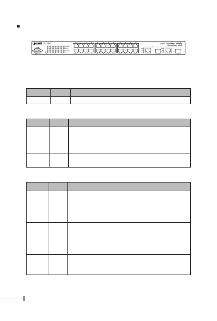
Figure 2-2 shows front panel of FGSW-2620RS.
Figure 2-2 PLANET FGSW-2620RS Front Panel
2.1.3 LED Indicators
System
LED Color
Function
PWR Green Lit: Power on
Per 10/100Mbps port
LED Color
Function
LNK/ACT Green
Lit: indicate the link through that port is successfully es
-
tablished.
Blink: indicate that the switch is actively sending or receiv
-
ing data over that port.
100 Orange
Lit: indicate that the port is operating at 100Mbps.
Off: indicate that the port is operating at 10Mbps.
Per 10/100/1000Base-T port /SFP interfaces
LED Color
Function
LNK/ACT
1000
Green
Lit: indicate that the port is operating at 1000Mbps.
Off: indicate that the port is operating at 10Mbps or
100Mbps.
Blink: indicate that the switch is actively sending or receiv
-
ing data over that port.
LNK/ACT
100
Green
Lit: indicate that the port is operating at 100Mbps.
Off: indicate that the port is operating at 10Mbps or
1000Mbps.
Blink: indicate that the switch is actively sending or receiv
-
ing data over that port.
FDX
Green
Lit: indicate that the port is operating at full-duplex mode.
Off: indicate that the port is operating at half-duplex
mode.
Page 11

7
2.1.4 10/100/1000Base-T port / SFP interfaces
The TP / SFP interfaces #17, #18 or #25, #26 of FGSW-1820RS /FGSW-2620RS can be
a 10/100Base-TX, 1000Base-T or 1000Base-SX/LX/LX WDM switching port. Please refer
to the section 3.2.4.1 Port for the detailed installation and settings.
2.1.5 The Rear Panel
The rear panel of the Switch indicates an AC inlet power socket, which accepts input
power from 100 to 240VAC, 50-60Hz. Figure 2-3 shows Rear panel of the Switch.
Figure 2-3 Rear Panel of The Switch
Power Notice:
1. The device is a power-required device, it means, it will not work till it is pow-
ered. If your networks should active all the time, please consider using UPS
(Uninterrupted Power Supply) for your device. It will prevent you from network
data loss or network downtime.
2. In some area, installing a surge suppression device may also help to protect
your Switch from being damaged by unregulated surge or current to the Switch
or the power adapter.
2.2 Installing the Switch
This part describes how to install your Ethernet Smart Switch and make connections to
the Switch. Please read the following topics and perform the procedures in the order
being presented.
To install your Switch on a desktop or shelf, simply complete the following steps.
2.2.1 Desktop Installation
To install a Switch on a desktop or shelf, simply complete the following steps:
Step1: Attach the rubber feet to the recessed areas on the bottom of the Switch.
Step2: Place the Switch on a desktop or shelf near an AC power source.
Step3: Keep enough ventilation space between the Switch and the surrounding objects.
Note:
When choosing a location, please keep in mind the environmental
restrictions discussed in Chapter 1, Section 4, Specification.
Step4: Connect your Switch to network devices
A. Connect one end of a standard network cable to the 10/100 RJ-45 ports on the
Page 12
8
front of the Switch.
B. Connect the other end of the cable to the network devices such as printer serv-
ers, workstations or routers…etc.
Note:
Connection to the Switch requires UTP Category 5 network cabling
with RJ-45 tips. For more information, please see the Cabling
Specification in Appendix A.
Step5: Supply power to the Switch.
A. Connect one end of the power cable to the Switch.
B. Connect the power plug of the power cable to a standard wall outlet then power
on the Switch.
When the Switch receives power, the Power LED should remain solid Green.
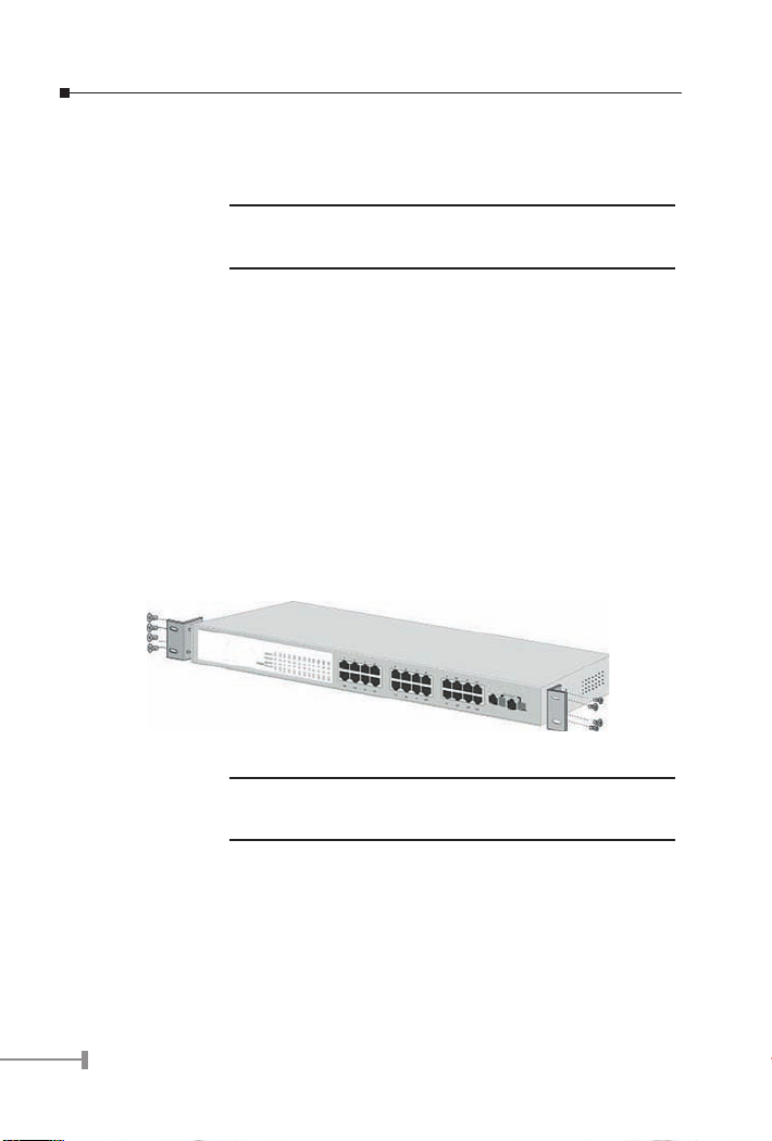
2.2.2 Rack Mounting
To install the Switch in a 19-inch standard rack, follow the instructions described below.
Step1: Place your Switch on a hard flat surface, with the front panel positioned towards
your front side.
Step2: Attach a rack-mount bracket to each side of the Switch with supplied screws
attached to the package. Figure 2-4 shows how to attach brackets to one side of
the Switch.
Figure 2-4 Attaching the brackets to the Switch
Caution:
You must use the screws supplied with the mounting brackets.
Damage caused to the parts by using incorrect screws would invalidate your warranty.
Step3: Secure the brackets tightly.
Step4: Follow the same steps to attach the second bracket to the opposite side.
Step5: After the brackets are attached to the Switch, use suitable screws to securely
attach the brackets to the rack, as shown in figure 2-5.
Page 13

9
Figure 2-5 Mounting the Switch in a Rack
Step6: Proceed with the steps 4 and steps 5 of section 2.2.1 Desktop Installation to
connect the network cabling and supply power to your Switch.
Page 14

10
Chapter 3
Console Configuration
Unlike the unmanaged switch, the Smart Switch perform series smart functions that
make the Switch operate more effectively. This section will describe the common usage of
the Switch Smart Configuration.
Note:
The following section will base on the console screens of FGSW2620RS, for FGSW-1820RS the display will be the same to FGSW2620RS.
3.1 Preparing for configuration
3.1.1 Connecting a PC or Terminal to the RS-232 Port
When you are ready to configure the smart functions of the Switch, make sure you had
connected the supplied RS-232 serial cable to the RS-232 port at the front panel of your
Switch and your PC.
3.1.2 Terminal Emulation Setup Program
In Windows 98/ 2000/ XP, launch “HyperTerminal”, create a new connection, and adjust
settings as below:
• Emulation: VT-100 compatible
• Baud per second: 19200
• Data bits: 8
• Parity: None
• Stop bits: 1
• Flow Control: None
To get a demonstration, please see the figure 3-1.
Page 15

11
Figure 3-1 Console Port Settings for smart functions
3.1.3 Power-up Self-test Status
As the Switch powers on, it goes through a self-test process to ensure proper operations
of the Switch hardware. The messages will be displayed to show the test progress. When
the test completes successfully, the system will display a login screen. If any of the
components fails during the test, you may need to contact your local dealer and have the
Switch replaced. Figure 3-2 shows a successful Self-test menu of the Power-up System
Self-diagnostic Process.
Figure 3-2 Power-up System Self-diagnostic screen
Page 16

12
3.1.4 Login
After the self-test completes successfully, the screen in figure 3-3 appears. Login is
required to access the console interface. The factory default username is “admin” without
password. You may change it in the Password. To access to the Main Menu, please always
enter the correct username and password.
Figure 3-3 Switch Console Login screen
3.2 Getting Started
3.2.1 General Guidelines
Switch allows users to configure the device via menu screens.
To work within the menu, please follow the guidelines shown in Table 3-1.
Item Description
Value 1-7
Choose one item from the console main screen.
I / M / J / L KEY Means up, down, left, right.
1 / 2 KEY Page up / Page down.
S KEY Save the current configuration.
F KEY Refresh screen
SPACE KEY When a List item is performed, the Space key starts
the selection and scrolls through the available choices.
0 KEY Return to the previous menu.
Table 3-1 General Guideline within the Menu
3.2.2 Main Menu Screen
The main menu enables you to view and manage the Switch settings. Press “value 1-7”
key on your keyboard for chooses Smart function of Switch. After entering into any smart
function screen, use “I / M / J / L” for configuring. Then Press the “Space Bar” to toggle
back and forth between the options. After setup completed, press “F” key to refresh
Page 17

13
screen and press the ”S” key for save the current configuration. Please refer to figure 3-4
for available options on main menu.
Figure 3-4 Main Menu Screen
1. Status
Allow user to view the basic information of the Switch. The available options are
Switch overview, MIB counter and Port Status. Explained on section 3.2.3.
2. Configuration
Allow user to perform the smart functions of the Switch. Explained on section
3.2.4.
3. Security
Reserved for further management purpose. Explained in section 3.2.5.
4. Diagnostics
Allow user to view the information about the Trunk link warning and Network
loop fault port detected. Explained in section 3.2.6.
5. Password
Allow user to change the username and password. Explained in section 3.2.7.
6. Reboot Switch
Allow user to reboot the Switch. Explained in section 3.2.8.
7. Logout
Allow user to logout the Switch console interface. Explained in section 3.2.9.
3.2.3 Port Status
Press 1 on your keyboard to access the screen of Status from the Main Menu screen
(please see the figure3-4). The screen of Status in figure 3-5 appears. Table 3-2 describes
the Status objects of Switch.
Page 18

14
Figure 3-5 Status Screen
Object Description
Overview Display the Switch information. Explained in section
3.2.3.1
MIB Counter Display the traffic counter on each port. Explained in sec-
tion 3.2.3.2
Port Status Display the current status of each port. Explained in sec
-
tion 3.2.3.3
Table 3-2 Descriptions of the Status screen Objects
3.2.3.1 Overview
This function display the Switch information, the available items are Switch name, Switch
MAC ID, Chip Model ID and Vender ID. The screen in figure 3-6 appears.
Figure 3-6 Overview Screen
3.2.3.2 MIB Counter
This function provides Ethernet traffic transmits / receive counter on each port. The screen
in figure 3-7 appears. Please refer to the guidelines shown in table 3-3.
Page 19

15
Figure 3-7 MIB Counter Screen
Item Description
1 / 2 KEY Page up / Page down.
0 KEY Return to the previous menu.
F KEY Refresh screen.
C KEY Clean all counter traffic on each port.
P/ X KEY Start / Stop polling.
T KEY Toggle Drop/ CRC/ Collision.
B KEY Toggle Byte/ Packet unit.
Table 3-3 Guideline within the MIB Counter screen
3.2.3.3 Port Status
This function displays the real-time status on each port of the Switch. The screen in figure
3-8 appears. Please refer to the guidelines shown in table 3-4.
Figure 3-8 Port Status Screen
Page 20

16
Item Description
1 / 2 KEY Page up / Page down.
0 KEY Return to the previous menu.
F KEY Refresh screen.
Table 3-4 Guideline within the Port Status screen
3.2.4 Port Configuration
Press 2 on your keyboard to access the screen of Configuration from the Main Menu screen
(please see the figure 3-4). The screen of Configuration in figure 3-9 appears. Table 3-5
describes the Configuration objects of Switch.
Figure 3-9 Configuration Screen
Object Description
Port This function allow user to setting each port of
Switch. Explained in section 3.2.4.1.
Trunking Allow user to disable or enable the trunk function.
Explained in section 3.2.4.2.
Global Allow user to disable or enable the Global func-
tions. Explained in section 3.2.4.3.
QoS Allow user to disable or enable the QoS functions.
Explained in section 3.2.4.4.
Priority Tag Insert/ Re
-
move
Allow user to insert or remove the priority Tag on
each port of Switch. Explained in section 3.2.4.5.
VLAN Global Control Allow user to disable or enable the VLAN Global
capabilities. Explained in section 3.2.4.6.
VLAN Member Setup Allow user to create VLAN group. Explained in sec-
tion 3.2.4.7.
Page 21

17
Device Features Allow user to disable or enable IGMP Snooping and
indicate the IP Multicast Router Port. Explained in
section 3.2.4.8.
Table 3-5 Descriptions of the Configuration screen Objects
3.2.4.1 Port
Press 1 on your keyboard to access the screen of Port from the Configuration screen
(please see the figure 3-9). This function allows user to setting each port of Switch, the
screen in figure 3-10 appears.
Figure 3-10 Port Configuration Screen
Please use I / M / J / L (Up / Down / Left / Right) key to move the highlight to the object
and press the “Space Bar” key to toggle back and forth between the options. After setup
completed, press “S” key to saving the current configuration. Then press “R” to restart
the Auto-negotiation to ensure the setting activated immediately. Table 3-6 describes the
Port objects.
Item Description
Enabled Allow disable or enable each port. If the port status is
disabled then this port will not receive or transmit any
packet. Default mode: enable.
Speed adver-tise
-
ment
Allow set the port link speed and duplex mode base on
auto-negotiation. Default mode: 100M Full (10/100Mbps
port); 1000M Full (Gigabit port).
Flow Control Allow disable or enable flow control.
Default mode: Enable.
Rx Bandwidth Per port packet transmission control (128K, 256K, 512K,
1M, 2M, 4M, 8M). Default mode: non-control.
Tx Bandwidth Per port packet transmission control (128K, 256K, 512K,
1M, 2M, 4M, 8M). Default mode: non-control.
Table 3-6 Descriptions of the Port screen Objects
Page 22

18
Notice:
Be noted, the Switch support auto-negotiation at each port, please remain in option “100M Full”, “1000M Full” (port#17/18 or port#25/26) if
the other device do not support auto-negotiation. If a device does not
support auto-negotiation, the Switch will auto-detect the optimal speed
at half-duplex, i.e. 100Mbps half-duplex or 10Mbps half-duplex. Also
be noted that in Gigabit module both of devices must support autonegotiation. Please refer to the tables below:
Link status of the device using Auto-negotiation to the Switch
Switch’s
Speed Advertise setting
Device mode setting
1000M Full 100M Full 100M Half 10M Full 10M Half
1000M Full*
1000 Full 100M Full 100M Half 10M Full 10M Half
100M Full
100M Full 100M Full 100M Half 10M Full 10M Half
100M Half
100M Half 100M Half 100M Half 10M Full 10M Half
10M Full
10M Full 10M Full 10M Full 10M Full 10M Half
10M Half
10M Half 10M Half 10M Half 10M Half 10M Half
Link status of the device using Auto-negotiation to the Switch
Switch’s
Speed Advertise setting
Device mode setting
1000M Full 100M Full 100M Half 10M Full 10M Half
1000M Full* 1000 Full 100M Full 100M Half 10M Full 10M Half
100M Full 100M Full 100M Full 100M Half 10M Full 10M Half
100M Half 100M Half 100M Half 100M Half 10M Full 10M Half
10M Full 10M Full 10M Full 10M Full 10M Full 10M Half
10M Half 10M Half 10M Half 10M Half 10M Half 10M Half
1. Fields with gray color is recommended setting in the Switch.
2. NC means no communication.
3. 1000M Full setting can be found only in port #17/18 of FGSW-1820RS or port
#25/26 of FGSW-2620RS.
Though device with forced full-duplex mode build the link with the Switch, the performance
could be bad due to the devices runs in Full while the Switch runs in Half-duplex.
3.2.4.2 Trunking
Press 2 on your keyboard to access the screen of Trunking from the Configuration screen
(please see the figure 3-9).
Page 23

19
The screen of Trunking in figure 3-11 appears. Table 3-7 shows the descriptions of the
Trunking screen Objects. The Trunking Configuration menu controls the trunking or the
so-called Link Aggregation function. There are 6/8 Trunk groups in the FGSW-1820RS/
FGSW-2620RS can be bundled together to form a high-speed trunk. Please use I / M (Up
/ Down) key to move the high-light to the object and press the “Space Bar” key to toggle
back and forth between the options. After setup completed, press “S” key to saving the
current configuration.
Figure 3-11 Trunking Screen
Object Description
Trunking Provide 6/8 trunk groups in FGSW-1820RS/ FGSW-2620RS,
maximum up to 4 ports per trunk.
Enable Allow disable or enable each trunk group.
Table 3-7 Descriptions of the Trunking Screen Objects
Notice:
The Switch at the other end must enable the trunking function with the
same port count to get the optimal usage of the trunk-bandwidth.
3.2.4.3 Global
Press 3 on your keyboard to access the screen of Global from the Configuration screen
(please see the figure 3-9).
The screen of Global in figure 3-12 appears. Table 3-8 shows the descriptions of the Global
screen Objects.
Figure 3-12 Global Screen
Page 24

20
Object Description
Half duplex back
pressure flow
Provide disable or enable half duplex backpressure flow.
To disable will turn off the half-duplex back pressure con-
trol and drop the packets without sending out any collision
from that Switch port after the Switch’s data buffer over
-
flow. Default: Enable.
Broadcast storm
filtering control
Provide disable or enable broadcast storm filtering. Enable
will turn on the capability to drop broadcast packets after a
continuous 64 broadcast packets. Default: Disable.
Loop Detect Provide disable or enable loop detect function. To turn on
will loop detect the connection status. This feature is used
for diagnose purpose. Default: Disable.
Table 3-8 Descriptions of the Global Screen Objects
3.2.4.4 QoS
Press 4 on your keyboard to access the screen of QoS from the Configuration screen
(please see the figure 3-9). The screen of QoS in figure 3-13 appears. Table 3-9 shows
the descriptions of the QoS screen Objects.
Figure 3-13 QoS Screen
Object Description
TOS/Diff Serv priority Provide disable or enable TOS priority. Check the
packets’ IP TOS priority tag and base on the priority
to forward the packets. Default: Disable.
802.1p priority Provide disable or enable 802.1p priority. Check the
packet’s 802.1p priority and base on the priority to
forward the packets. Default: Disable.
Adapted flow control Provide disable or enable priority of flow control.
Check the priority and turn off the flow-control when
high priority packets received. Default: Disable.
Page 25

21
Priority weight ration
(high:low)
Use “M” key to move down to Priority weight ration
then use Space key to select the ration priority. Avail-
able weights, 1:0; 4:1, 8:1, 16:1. Default: 16:1.
Force set high-priority
port
Use “M” key to move down the cursor and select the
ports, by Space toggle, that you would like to set base
on the QoS options above.
Table 3-9 Descriptions of the QoS Screen Objects
3.2.4.5 Priority Tag Insert / Remove
Press 5 on your keyboard to access the screen of Priority Tag Insert / Remove from the
Configuration screen (please see the figure 3-9).
The screen of Priority Tag Insert / Remove in figure 3-14 appears. Table 3-10 shows the
descriptions of the Priority Tag Insert / Remove screen Objects.
Figure 3-14 Priority Tag Insert / Remove Screen
Object Description
Insert Tag (high priority only) Insert priority tag into the untagged high-priority
frame
Insert Tag (all frame) Insert priority tag into the all untagged frame
Remove Tag Remove the VLAN tag from all tagged frame
Don’t touch The default setting, which means no modify
Table 3-10 Descriptions of the Priority Tag Insert / Remove Screen Objects
3.2.4.6 VLAN Global Control
Press 6 on your keyboard to access the screen of VLAN Global Control from the
Configuration screen (please see the figure 3-9).
The screen of VLAN Global Control in figure 3-15 appears. Table 3-11 shows the
descriptions of the VLAN Global Control screen Objects.
Page 26

22
Figure 3-15 VLAN Global Control Screen
Object Description
VLAN function Allow disable or enable VLAN function.
Default: disable
Unicast packet
Inter-
VLAN Leaky
Allow disable or enable the packet to be forward to a des
-
tination port at different VLAN.
Default: disable
ARP broadcast
packet Inter-VLAN
Leaky
Allow to disable or enable ARP frame to broadcast to all
switch port.
Default: disable
IP Multicast packet
Inter-VLAN Leaky
Allow to disable or enable multicast to be flood to the
entire multicast group member.
Default: disable
802.1Q VLAN tag
aware
Allow to disable or enable IEEE 802.1Q VLAN Tag aware.
Default: disable
Ingress Rule for
Acceptable frame
types
To permit all frames or VLAN-tagged frames.
Default: Admin all frames
Ingress Rule for
Ingress filtering
Allow to disable or enable filter the frame received from a
port which port is not in the classified VLAN group mem-
ber.
Default: disable
Table 3-11 VLAN Global Control Screen Objects
Notice:
The Ingress rule only allows use for additional IEEE 802.1Q VLAN
operation mode. That is the connected devices, such as any third party
switch, workstations, servers should also support IEEE 802.1Q VLAN
tag fecauters.
Page 27

23
3.2.4.7 VLAN Member Setup
Press 7 on your keyboard to access the screen of VLAN Member Setup from the
Configuration screen (please see the figure 3-9).
The screen of VLAN Member Setup in figure 3-16 appears.
Figure 3-16 VLAN Member Setup Screen
Port-based VLAN setup procedure:
1.Please press “E” key change to “Edit mode”.
2.Please press “A” key to add port-based VLAN group.
3.Please use “L” key move to specific port then press “space” key to add this port
into current VLAN group.
4. After setup completed, please press “Enter” key to update the VLAN table.
5.Please press “S” key to save the current VLAN configuration.
3.2.4.8 Device Features
Press 8 on your keyboard to access the screen of Device Features from the Configuration
screen (please see the figure 3-9).
The screen of Device Features in figure 3-17 appears. Table 3-12 shows the descriptions
of the Device Features screen Objects.
Figure 3-17 Device Features Screen
Page 28

24
Object Description
IGMP Snooping Allow disable or enable IGMP Snooping. This function
is support the ability of IGMP Control packets and IP
multicast data packets to learn the multicast router
port and group address member port into multicast
address table. Default: disable
Table 3-12 Device Features Screen Objects
3.2.5 Security
Press 3 on your keyboard to access the screen of Security from the Main Menu screen
(please see the figure 3-4). The screen of Configuration in figure 3-18 appears. This
function reserved for further management purpose.
Figure 3-18 Security Screen
3.2.6 Diagnostics
Press 4 on your keyboard to access the screen of Diagnostics from the Main Menu screen
(please see the figure 3-4). The screen of Diagnostics in figure 3-19 appears. Table 3-13
shows the descriptions of the QoS screen Objects.
Figure 3-19 Diagnostics Screen
Page 29

25
Object Description
Trunk Link Warning Display the trunk status at each group when trunk is en
-
abled.
Network loop Fault
Port Detected
Display the information loop detect when loop occur on
each port.
Table 3-13 Diagnostics Screen Objects
3.2.7 Password
Press 5 on your keyboard to access the screen of Password from the Main Menu screen
(please see the figure 3-4). The screen of Password in figure 3-20 appears.
Figure 3-20 Password Screen
Username and password modify procedure:
1. Please press “1” key to change the username, the screen in figure 3-21 & 3-22
appears.
Figure 3-21 Change username Screen
Page 30

26
2. Please press “Enter” to execute current configuration.
Figure 3-22 Change username successfully Screen
3 Please press “F” to refresh the screen.
4 Please press “2” key to change the password, the screen in figure 3-23 & 3-24
appears.
Figure 3-23 Change password Screen
5. Please press “Enter” to execute current configuration.
Figure 3-24 Change password successfully Screen
6. Please press “F” to refresh the screen.
Notice:
For security reason, please change and memorize the new username
and password after this first setup.
Page 31

27
3.2.8 Reboot
Press 6 on your keyboard to access the screen of Reboot from the Main Menu screen
(please see the figure 3-4). The screen of Reboot in figure 3-25 appears.
Figure 3-25 Reboot Switch Screen
Reboot and reset switch to default mode procedure:
1. Please press “D” key to reset switch to default mode, the screen in figure 3-26
& 3-27 appears.
Figure 3-26 Reset Switch to default mode Screen
Figure 3-27 Reset Switch to default mode Screen
2. Please press “F” to refresh the screen.
3. Please press “R” key to reboot Switch, the screen in figure 3-28 & 3-29 ap-
pears.
Page 32

28
Figure 3-28 Reboot Switch Screen
Figure 3-29 Reboot Switch Screen
Notice:
Choose “D” Default to reset the Switch to default mode. Not include the
modified username and password. Please memorize the new username
and password after change it.
3.2.9 Logout
Press 7 on your keyboard to access the screen of Logout from the Main Menu screen
(please see the figure 3-4). The screen of Logout in figure 3-30 appears.
Figure 3-30 Switch Logout Screen
Page 33

29
Press any key then the console login screen appears again. The screen in figure 3-31
appears.
Figure 3-31 Switch Login Screen
4. SWITCH OPERATION
4.1 Address Table
The Switch is implemented with an address table. This address table composed of many
entries. Each entry is used to store the address information of some node in network,
including MAC address, port no, etc. This information comes from the learning process
of Ethernet Switch.
4.2 Learning
When one packet comes in from any port, the Switch will record the source address, port
no. And the other related information in address table. This information will be used to
decide either forwarding or filtering for future packets.
4.3 Forwarding & Filtering
When one packet comes from some port of the Ethernet Switching, it will also check
the destination address besides the source address learning. The Ethernet Switching will
lookup the address-table for the destination address. If not found, this packet will be
forwarded to all the other ports except the port, which this packet comes in. And these
ports will transmit this packet to the network it connected. If found, and the destination
address is located at different port from this packet comes in, the Ethernet Switching will
forward this packet to the port where this destination address is located according to the
information from address table. But, if the destination address is located at the same port
with this packet comes in, then this packet will be filtered. Thereby increasing the network
throughput and availability
4.4 Store-and-Forward
Store-and-Forward is one type of packet-forwarding techniques. A Store-and-Forward
Ethernet Switching stores the incoming frame in an internal buffer, do the complete error
checking before transmission. Therefore, no error packets occurrence, it is the best choice
when a network needs efficiency and stability.
Page 34

30
The Ethernet Switch scans the destination address from the packet-header, searches the
routing table provided for the incoming port and forwards the packet, only if required. The
fast forwarding makes the switch attractive for connecting servers directly to the network,
thereby increasing throughput and availability. However, the switch is most commonly
used to segment existence hubs, which nearly always improves overall performance. An
Ethernet Switching can be easily configured in any Ethernet network environment to
significantly boost bandwidth using conventional cabling and adapters.
Due to the learning function of the Ethernet switching, the source address and
corresponding port number of each incoming and outgoing packet are stored in a routing
table. This information is subsequently used to filter packets whose destination address is
on the same segment as the source address. This confines network traffic to its respective
domain, reducing the overall load on the network.
The Switch performs “Store and forward” therefore, no error packets occur. More reliably,
it reduces the re-transmission rate. No packet loss will occur.
4.5 Auto-Negotiation
The STP ports on the Switch have built-in “Auto-negotiation”. This technology automatically
sets the best possible bandwidth when a connection is established with another network
device (usually at Power On or Reset). This is done by detect the modes and speeds at
the second of both device is connected and capable of, Both 10Base-T and 100Base-TX
devices can connect with the port in either Half- or Full-Duplex mode.
If attached device is: 100Base-TX port will set to:
•10Mbps, no auto-negotiation 10Mbps
•10Mbps, with auto-negotiation 10/20Mbps (10Base-T/Full-Duplex)
•100Mbps, no auto-negotiation 100Mbps
•100Mbps, with auto-negotiation 100/200Mbps
(100Base-TX/Full-Duplex)
5. TROUBLESHOOTING
This chapter contains information to help you solve problems. If the Ethernet Switch is not
functioning properly, make sure the Ethernet Switch was set up according to instructions
in this manual.
The Link LED is not lit
Solution:
Check the cable connection and remove duplex mode of the Ethernet Switch
Page 35

31
Some stations cannot talk to other stations located on
The other port
Solution:
Please check the VLAN settings, trunk settings, or port enabled / disabled status.
Performance is bad
Solution:
Check the full duplex status of the Ethernet Switch. If the Ethernet Switch is set to full
duplex and the partner is set to half duplex, then the performance will be poor. Please
also check the in/out rate of the port.
Why the Switch doesn’t connect to the network
Solution:
Check the LNK/ACT LED on the switch
Try another port on the Switch
Make sure the cable is installed properly
Make sure the cable is the right type
Turn off the power. After a while, turn on power again
APPENDIX A NETWORKING CONNECTION
A.1 Switch‘s RJ-45 Pin Assignments
1000Mbps, 1000Base-T
Contact MDI MDI-X
1 BI_DA+ BI_DB+
2 BI_DA- BI_DB-
3 BI_DB+ BI_DA+
4 BI_DC+ BI_DD+
5 BI_DC- BI_DD-
6 BI_DB- BI_DA-
7 BI_DD+ BI_DC+
8 BI_DD- BI_DC-
Page 36

32
10/100Mbps, 10/100Base-TX
RJ-45 Connector pin assignment
Contact MDI
Media Dependant Interface
MDI-X
Media Dependant Interface -Cross
1. Tx + (transmit) Rx + (receive)
2. Tx - (transmit) Rx - (receive)
3. Rx + (receive) Tx + (transmit)
4,5 Not used
6 Rx - (receive) Tx - (transmit)
7,8 Not used
A.2 RJ-45 cable Pin Assignments
The standard RJ-45 receptacle/connector
There are 8 wires on a standard UTP/STP cable and each wire is color-coded. The
following shows the pin allocation and color of straight cable and crossover cable
connection:
Figure A-1: Straight-Through and Crossover Cable
Please make sure your connected cables are with same pin assignment and color
as above picture before deploying the cables into your network.
Page 37

Page 38

Part No.:2010-A81120-000
 Loading...