

Page 1
User’s Manual of FGSW-1816HPS
1
Page 2

User’s Manual of FGSW-1816HPS
Trademarks
Copyright © PLANET Technology Corp. 2014.
Contents are subject to revision without prior notice.
PLANET is a registered trademark of PLANET Technology Corp. All other trademarks belong to their respective owners.
Disclaimer
PLANET Technology does not warrant that the hardware will work properly in all environments and applications, and makes no
warranty and representation, either implied or expressed, with respect to the quality, performance, merchantability, or fitness for
a particular purpose. PLANET has made every effort to ensure that this User's Manual is accurate; PLANET disclaims liability
for any inaccuracies or omissions that may have occurred.
Information in this User's Manual is subject to change without notice and does not represent a commitment on the part of
PLANET. PLANET assumes no responsibility for any inaccuracies that may be contained in this User's Manual. PLANET makes
no commitment to update or keep current the information in this User's Manual, and reserves the right to make improvements to
this User's Manual and/or to the products described in this User's Manual, at any time without notice.
If you find information in this manual that is incorrect, misleading, or incomplete, we would appreciate your comments and
suggestions.
FCC Warning
This equipment has been tested and found to comply with the limits for a Class B digital device, pursuant to Part 15 of the FCC
Rules. These limits are designed to provide reasonable protection against harmful interference when the equipment is operated
in a commercial environment. This equipment generates, uses, and can radiate radio frequency energy and, if not installed and
used in accordance with the Instruction manual, may cause harmful interference to radio communications. Operation of this
equipment in a residential area is likely to cause harmful interference in which case the user will be required to correct the
interference at his own expense.
CE Mark Warning
This is a Class B product. In a domestic environment, this product may cause radio interference, in which case the user may be
required to take adequate measures.
Energy Saving Note of the Device
This power required device does not support Standby mode operation. For energy saving, please remove the power cable to
disconnect the device from the power circuit. In view of saving the energy and reducing the unnecessary power consumption, it
is strongly suggested to remove the power connection for the device if this device is not intended to be active.
WEEE Warning
To avoid the potential effects on the environment and human health as a result of the presence of hazardous
substances in electrical and electronic equipment, end users of electrical and electronic equipment should
understand the meaning of the crossed-out wheeled bin symbol. Do not dispose of WEEE as unsorted
municipal waste and have to collect such WEEE separately.
Revision
PLANET 16-Port 10/100TX 802.3at PoE + 2-Port Gigabit TP/SFP ComboWeb Smart Ethernet Switch User's Manual
FOR MODEL: FGSW-1816HPS
REVISION: 1.0 (July 2014)
Part No: EM-FGSW-1816HPS_v1.0 (2080-AK8080-000)
2
Page 3

User’s Manual of FGSW-1816HPS
TABLE OF CONTENTS
1. INTRODUCTION....................................................................................................................6
1.1 Packet Contents ...........................................................................................................................................6
1.2 Product Description.....................................................................................................................................7
1.3 How to Use This Manual............................................................................................................................10
1.4 Product Features........................................................................................................................................11
1.5 Product Specifications ..............................................................................................................................13
2. INSTALLATION ................................................................................................................... 15
2.1 Hardware Description................................................................................................................................15
2.1.1 Switch Front Panel ..............................................................................................................................................15
2.1.2 LED Indications ...................................................................................................................................................16
2.1.3 Switch Rear Panel ...............................................................................................................................................17
2.2 Installing the Switch...................................................................................................................................18
2.2.1 Desktop Installation .............................................................................................................................................18
2.2.2 Rack Mounting.....................................................................................................................................................19
2.2.3 Installing the SFP transceiver ..............................................................................................................................20
3. SWITCH MANAGEMENT....................................................................................................23
3.1 Requirements..............................................................................................................................................23
3.2 Management Access Overview.................................................................................................................24
3.3 Web Management.......................................................................................................................................24
3.4 SNMP-based Network Management.........................................................................................................25
4. WEB CONFIGURATION
......................................................................................................26
4.1 Main Web Page...........................................................................................................................................28
4.2 System.........................................................................................................................................................30
4.2.1 System Information..............................................................................................................................................30
4.2.2 IP Configurations .................................................................................................................................................31
4.2.3 Password Setting.................................................................................................................................................32
4.2.4 Factory Default ....................................................................................................................................................32
4.2.5 Firmware Update .................................................................................................................................................33
4.2.6 Reboot .................................................................................................................................................................35
3
Page 4

User’s Manual of FGSW-1816HPS
4.2.7 NTP Setting .........................................................................................................................................................35
4.3 Port Management .......................................................................................................................................37
4.3.1 Port Configuration................................................................................................................................................38
4.3.2 Port Mirroring.......................................................................................................................................................40
4.3.3 Bandwidth Control ...............................................................................................................................................41
4.3.4 Broadcast Storm Control......................................................................................................................................43
4.3.5 Port Statistics.......................................................................................................................................................44
4.4 VLAN............................................................................................................................................................46
4.4.1 VLAN Overview ...................................................................................................................................................46
4.4.2 VLAN Basic Information.......................................................................................................................................48
4.4.2.1 Port-based VLAN mode.............................................................................................................................48
4.4.2.2 Tag-based VLAN Mode .............................................................................................................................48
4.4.3 VLAN Port Configuration .....................................................................................................................................50
4.4.3.1 Port-based VLAN Mode.............................................................................................................................50
4.4.3.2 Tag-based VLAN Mode .............................................................................................................................51
4.4.4 Multi to 1 Setting..................................................................................................................................................52
4.5 Quality of Service.......................................................................................................................................53
4.5.1 QoS overview ......................................................................................................................................................53
4.5.2 Priority Mode .......................................................................................................................................................53
4.5.3 Class of Service Configuration ............................................................................................................................54
4.5.4 TCP/UDP Port Based QoS ..................................................................................................................................55
4.6 Security .......................................................................................................................................................57
4.6.1 MAC Address Filter..............................................................................................................................................57
4.6.2 TCP/UDP Filter....................................................................................................................................................58
4.7 Spanning Tree.............................................................................................................................................60
4.7.1 STP Bridge Settings ............................................................................................................................................66
4.7.2 STP Port Settings ................................................................................................................................................68
4.7.3 Loopback Detection.............................................................................................................................................70
4.8 Trunking Setting.........................................................................................................................................72
4.8.1 Link Aggregation Settings....................................................................................................................................74
4.9 DHCP Relay Agent......................................................................................................................................76
4.9.1 DHCP Relay Agent ..............................................................................................................................................76
4.9.2 DHCP Relay Server.............................................................................................................................................77
4.9.3 VLAN MAP Relay Agent ......................................................................................................................................78
4.10 PoE Setting ...............................................................................................................................................79
4.10.1 Power over Ethernet Powered Device...............................................................................................................79
4
Page 5

User’s Manual of FGSW-1816HPS
4.10.2 PoE Status.........................................................................................................................................................80
4.10.3 PoE Port Setting ................................................................................................................................................81
4.10.4 Port Sequential ..................................................................................................................................................84
4.10.5 PoE Schedule....................................................................................................................................................85
4.11 Configuration Backup / Upload...............................................................................................................88
4.12 Misc Operation .........................................................................................................................................89
4.13 SNMP.........................................................................................................................................................94
4.14 Logout .......................................................................................................................................................96
5. SWITCH OPERATION.........................................................................................................97
5.1 Address Table.............................................................................................................................................97
5.2 Learning ......................................................................................................................................................97
5.3 Forwarding & Filtering...............................................................................................................................97
5.4 Store-and-Forward.....................................................................................................................................97
5.5 Auto-Negotiation ........................................................................................................................................98
6. Power over Ethernet Overview..........................................................................................99
7. TROUBLESHOOTING....................................................................................................... 101
APPENDIX A .........................................................................................................................103
A.1 Switch's RJ-45 Pin Assignments ...........................................................................................................103
A.2 10/100Mbps, 10/100Base-TX...................................................................................................................103
5
Page 6

User’s Manual of FGSW-1816HPS
1. INTRODUCTION
Thanks you for purchasing 16-Port 10/100Base-TX 802.3at PoE + 2-Port Gigabit TP/SFP Combo Web Smart Ethernet Switch,
FGSW-1816HPS. “PoE Web Smart Switch” mentioned in this Guide refers to the FGSW-1816HPS.
1.1 Packet Contents
Open the box of the PoE Web Smart Switch and carefully unpack it. The box should contain the following items:
The PoE Web Smart Switch
Quick Installation Guide
SFP Dust Cap
Rubber Feet
Rack Mount Accessory Kit
Power Cord
If any item is found missing or damaged, please contact your local reseller for replacement.
x1
x1
x2
x4
x1
x1
6
Page 7
User’s Manual of FGSW-1816HPS
1.2 Product Description
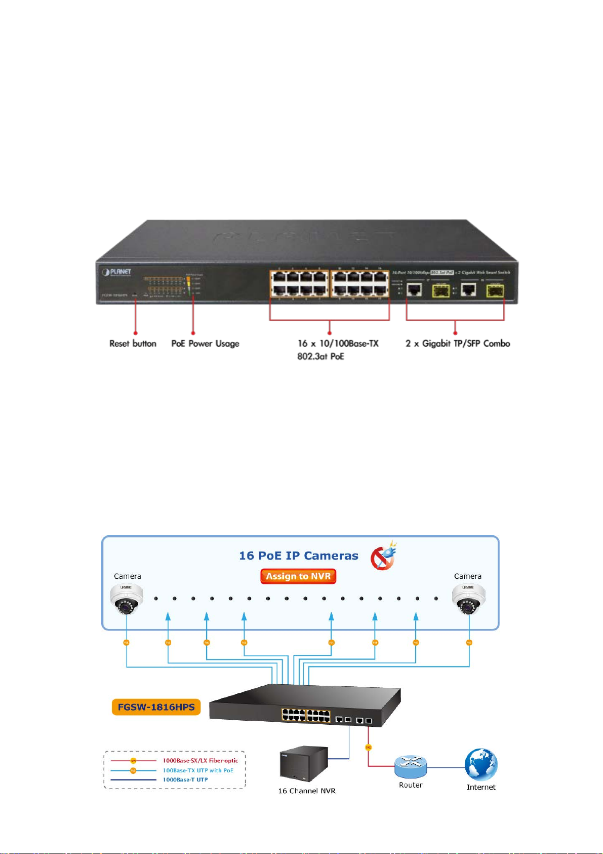
Ideal Solution for Secure IP Surveillance Infrastructure
Particularly designed for the growing popular IP surveillance applications, PLANET FGSW-1816HPS 802.3at PoE web smart
switch is positioned as a surveillance switch with the central management of remote power control and IP camera monitoring.
The FGSW-1816HPS provides intelligent PoE functions along with 16 10/100Base-TX ports featuring 30-watt 802.3at PoE+
with RJ45 copper interfaces and 2 Gigabit TP/SFP combo interfaces supporting high-speed transmission of surveillance
images and videos.
Perfectly-integrated Solution for PoE IP Camera and NVR System
Being different from the general IT industry PoE switch which usually contains 12 or 24 PoE ports, the FGSW-1816HPS
provides 16 802.3at PoE+ ports for catering to medium to large scale of IP surveillance networks at a lower total cost. With its
7.2Gbps high-performance switch architecture and 220-watt PoE power budget, the recorded video files from 16 PoE IP
cameras can be powered by the FGSW-1816HPS and saved in the 8 / 16 / 32-channel NVR systems or surveillance software to
perform comprehensive security monitoring. For instance, one FGSW-1816HPS can be combined with one 16-channel NVR
and 16 PoE IP cameras as a kit for the administrators to centrally and efficiently manage the surveillance system in the local
LAN and the remote site via Internet.
7
Page 8
User’s Manual of FGSW-1816HPS
Intelligent LED Indicator for Real-time PoE Usage
The FGSW-1816HPS helps users to monitor the current status of PoE power usage easily and efficiently by its advanced LED
indication. Called “PoE Power Usage”, the front panel of the FGSW-1816HPS Fast Ethernet PoE+ Switch has four orange
LEDs indicating 50W, 100W, 150W and 190W of PoE power usage.
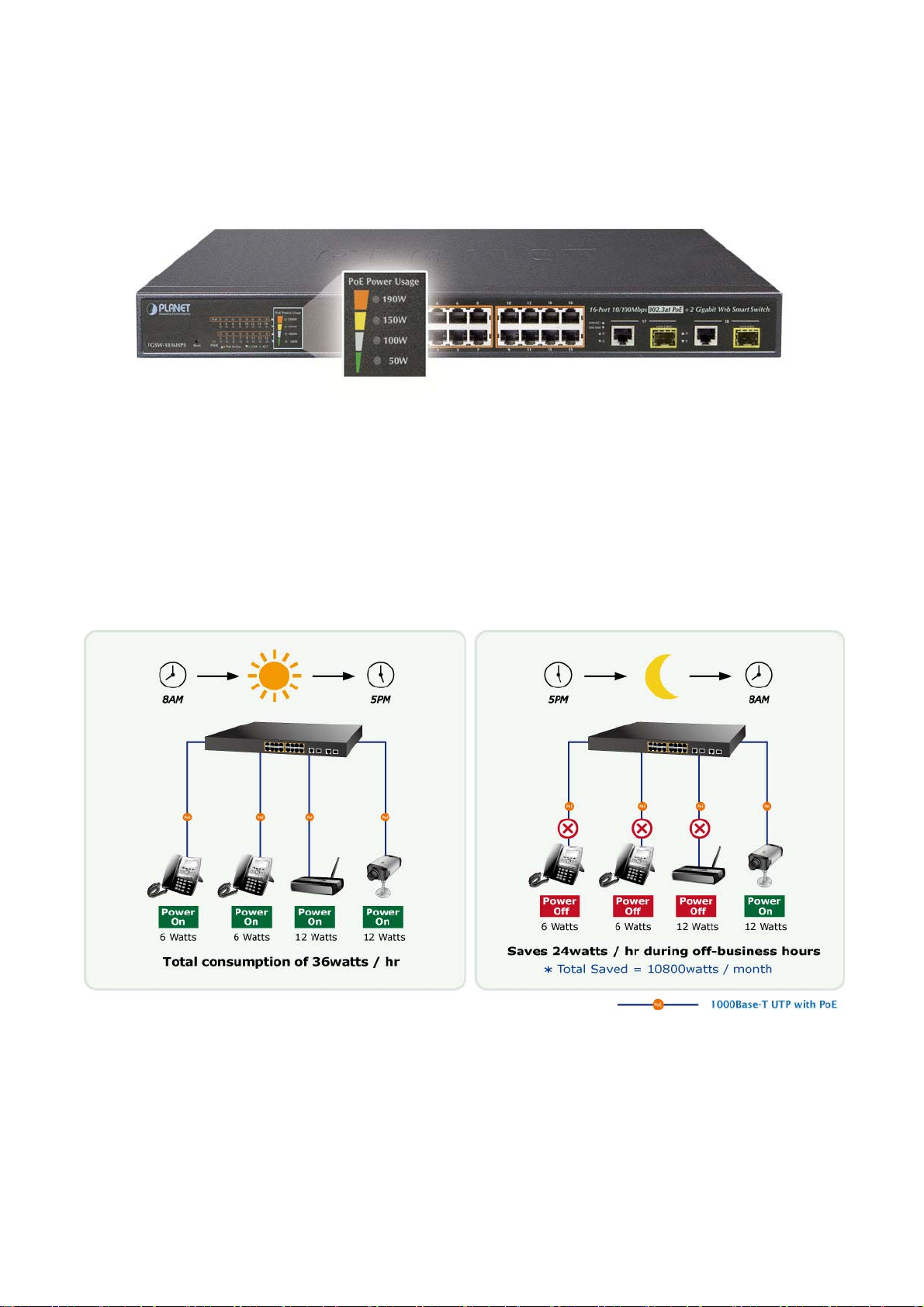
PoE Schedule for Energy Saving
Besides being used as an IP Surveillance, the FGSW-1816HPS is certainly applicable to constructing any PoE network
including VoIP and wireless LAN. Under the trend of energy saving worldwide and contributing to environmental protection on
the Earth, the FGSW-1816HPS can effectively control the power supply besides its capability of giving high watts power. The
“PoE schedule” function is for you to enable or disable PoE power feeding for each PoE port during specified time intervals and
it is a powerful function to help SMBs or enterprises save power and money.
Robust Layer 2 Features
The FGSW-1816HPS can be programmed for advanced switch management functions such as dynamic port link aggregation
(LACP), Spanning Tree Protocol (STP), IGMP Snooping v1, v2, bandwidth control and L2/L4 security control. The
FGSW-1816HPS provides IEEE 802.1Q tagged VLAN, port-based VLAN and MTU VLAN. The VLAN groups allowed will be
maximally up to 32. Via aggregation of supporting ports, the FGSW-1816HPS allows the operation of a high-speed trunk
combining multiple ports and supports fail-over as well.
8
Page 9

User’s Manual of FGSW-1816HPS
Flexible and Extendable Uplink Solution
The FGSW-1816HPS provides 2 extra Gigabit TP/SFP combo interfaces supporting 10/100/1000Base-T RJ-45 copper to
connect with surveillance network devices such as NVR, Video Streaming Server or NAS to facilitate surveillance
management. Or through these dual-speed fiber SFP slots, it can also connect with the 1000Base-SX/LX SFP (Small
Form-factor Pluggable) fiber transceiver to uplink to backbone switch and monitoring center in long distance. The distance can
be extended from 550m to 2km (multi-mode fiber), even going up to above 10/20/30/40/50/70/120km (single-mode fiber or
WDM fiber). They are well suited for applications within the enterprise data centers and distributions.
9
Page 10

User’s Manual of FGSW-1816HPS
1.3 How to Use This Manual
This User Manual is structured as follows:
Section 2, INSTALLATION
The section explains the functions of the Switch and how to physically install the PoE Web Smart Switch.
Section 3, SWITCH MANAGEMENT
The section contains the information about the software function of the PoE Web Smart Switch.
Section 4, WEB CONFIGURATION
The section explains how to manage the PoE Web Smart Switch by Web interface.
Section 5, SWITCH OPERATION
The chapter explains how to does the switch operation of the PoE Web Smart Switch.
Section 6, Power over Ethernet Overview
The chapter introduces the IEEE 802.3af / 802.3at PoE standard and PoE provision of the PoE Web Smart Switch.
Section 7, TROUBSHOOTING
The chapter explains how to troubleshoot the PoE Web Smart Switch.
Appendix A
The section contains cable information of the PoE Web Smart Switch.
10
Page 11

1.4 Product Features
Physical Port
16-port 10/100Base-TX RJ45 copper with PoE in-line supported
2-port 10/100/1000Base-T RJ45 copper
2 1000Base-X mini-GBIC/SFP slots to share with Port-17 to Port-18
Reset button for system management
Power over Ethernet
Complies with IEEE 802.3at High Power over Ethernet End-Span PSE
Complies with IEEE 802.3af Power over Ethernet End-Span PSE
Up to 16 IEEE 802.3at / 802.3af devices powered
Supports PoE Power up to 30.8 watts for each PoE port
Detects powered device (PD) automatically
Circuit protection prevents power interference between ports
Remote power feeding up to 100m
PoE Power Usage (50/100/150/190 watts)
PoE Management
Per port PoE function enable/disable
PoE Port Power feeding priority
Per PoE port power limit
PD classification detection
PoE Power sequential
PoE schedule
User’s Manual of FGSW-1816HPS
Layer 2 Features
Auto-MDI/MDI-X detection on each RJ45 port
Prevents packet loss with back pressure (half-duplex) and IEEE 802.3x pause frame flow control (full-duplex)
Supports broadcast storm control
Supports VLAN:
- IEEE 802.1Q tag-based VLAN, up to 32 VLANs groups, out of 4095 VLAN IDs
- Port-based VLAN, up to 16 VLAN groups
- MTU VLAN (Multi-tenant Unit VLAN)
Supports Link Aggregation
- 802.3ad Link Aggregation Control Protocol (LACP)
- Cisco ether-channel (Static Trunk)
Supports Spanning Tree Protocol
- STP, IEEE 802.1d Spanning Tree Protocol
- RSTP, IEEE 802.1w Rapid Spanning Tree Protocol
Port mirroring to monitor the incoming or outgoing traffic on a particular port
Provides port mirror (Many-to-1)
Loopback protection to avoid broadcast loops
Quality of Service
2 priority queues on all switch ports
Traffic classification
- Port-based priority
- IEEE 802.1p-based priority
- IP TOS / DSCP-based priority
11
Page 12

- TCP / UDP port-based QoS
Strict priority and Weighted Round Robin (WRR) CoS policies
Multicast
Supports IGMP Snooping v1 and v2
Security
Physical port to MAC address binding
TCP/UDP port number filter: Forwarding or discarding typical network applications
Port mirroring to monitor the incoming or outgoing traffic on a particular port
Management
Switch Management Interfaces
- Web switch management
- SNMP v1 switch management
Supports DHCP Option82 and DHCP Relay
Firmware upload/download via HTTP
Network Time Protocol (NTP)
Hardware reset button for system reboot or reset to factory default
PLANET smart discovery utility
User’s Manual of FGSW-1816HPS
12
Page 13

1.5 Product Specifications
Product FGSW-1816HPS
Hardware Specifications
User’s Manual of FGSW-1816HPS
10/100Mbps Copper Ports
Gigabit Copper Ports
SFP/mini-GBIC Slots
Switch Architecture
Switch Fabric
Throughput
Address Table
Share Data Buffer
Flow Control
Maximum Transmit Unit size
(MTU size)
Reset Button
Dimensions (W x D x H)
Weight
16 10/100Base-TX RJ45 Auto-MDI/MDI-X ports
2 10/100/1000Base-T RJ45 Auto-MDI/MDI-X ports
2 1000Base-X SFP interfaces, shared with Port-17 to Port-18
Store-and-Forward
7.2Gbps / non-blocking
5.35Mpps@64Bytes
4K entries, automatic source address learning and ageing
2.75Mb embedded memory for packet buffers
IEEE 802.3x pause frame for full-duplex
Back pressure for half-duplex
1536 Bytes
< 5 sec: System reboot
> 5 sec: Factory Default
440 x 200 x 44.5 mm, 1U height
2.55kg
System:
Power (Green)
10/100Base-TX RJ45 Interfaces (Port1 to Port16):
10/100Mbps LNK/ACT (Green)
LED
Power Requirements
Power Consumption
ESD Protection
Power over Ethernet
PoE Standard IEEE 802.3af / 802.3at PoE / PSE
PoE Power Supply Type End-span
PoE Power Output
Power Pin Assignment 1/2(+), 3/6(-)
PoE Power Budget
PoE In-Use (Orange)
10/100/1000Base-T RJ45 / SFP Interfaces (Port17 to Port18):
LNK/ACT (Green)
100/1000 (Green)
PoE Usage
50W, 100W, 150W, 190W (Orange)
100~240V AC, 50/60Hz, 4A
Max. 240 watts / 816 BTU
2KV DC
Per Port 56V DC, Max. 30.8 watts
220 watts (max.)
PoE
Ability
PD @ 7 watts
PD @ 15.4 watts
16 units
12 units
13
Page 14

User’s Manual of FGSW-1816HPS
PD @ 30.8 watts
Layer 2 Functions
Port Configuration
Port Status
Port Mirroring
VLAN
Link Aggregation
QoS
IGMP Snooping
Security Control
Management Functions
Basic Management Interfaces
7 units
Port disable / enable
Auto-negotiation 10/100/1000Mbps full and half duplex mode selection
Flow Control disable / enable
Display each port’s speed duplex mode, link status, flow control status, auto
negotiation status and trunk status
TX / RX / Both
Many-to-1 monitor
802.1Q tagged-based VLAN, up to 32 VLAN groups, out of 4094 VLAN IDs
Port-based VLAN, up to 18 VLAN groups
MTU VLAN
2 groups of 4-Port 10/100Base-TX trunk supported
1 group of 2-Port 10/100/1000Base-T trunk supported
Allow to assign low / high priority on each port
First-In-First-Out, All-High-before-Low, Weight-Round-Robin QoS policy
IGMP (v1/v2) Snooping, up to 32 multicast groups
MAC address binding
TCP & UDP filter
Web Browser, SNMP v1
Standards Conformance
Regulation Compliance
Standards Compliance
Twisted-Pair
Cable
Fiber-Optic
Cable
FCC Part 15 Class A, CE
IEEE 802.3 Ethernet
IEEE 802.3u Fast Ethernet
IEEE 802.3ab Gigabit Ethernet
IEEE 802.3z Gigabit Ethernet
IEEE 802.3x Full-duplex flow control
IEEE 802.1Q VLAN
IEEE 802.1p QoS
IEEE 802.1D Spanning Tree Protocol
IEEE 802.1w Rapid Spanning Tree Protocol
IEEE 802.3af Power over Ethernet
IEEE 802.3at Power over Ethernet Plus
10Base-T: 2-Pair UTP CAT. 3, 4, 5, up to 100 meters
100Base-TX: 2-Pair UTP CAT. 5, 5e up to 100 meters
1000Base-T: 4-Pair UTP CAT. 5e, 6 up to 100 meters
1000Base-SX :
50/125μm or 62.5/125μm multi-mode fiber optic cable, up to 550m (varying on
SFP module)
1000Base-LX :
9/125μm single-mode fiber optic cable, up to 10/20/30/40/50/70/120 kilometers
(varying on SFP module)
Environment
Operating
Storage
Temperature: 0 ~ 50 degrees C
Relative Humidity: 5 ~ 95% (non-condensing)
Temperature: -10 ~ 70 degrees C
Relative Humidity: 5 ~ 95% (non-condensing)
14
Page 15

User’s Manual of FGSW-1816HPS
2. INSTALLATION
This section describes the hardware features and installation of the PoE Web Smart Switch on the desktop or rack mount. For
easier management and control of the PoE Web Smart Switch, familiarize yourself with its display indicators, and ports. Front
panel illustrations in this chapter display the unit LED indicators. Before connecting any network device to the PoE Web Smart
Switch, please read this chapter completely.
2.1 Hardware Description
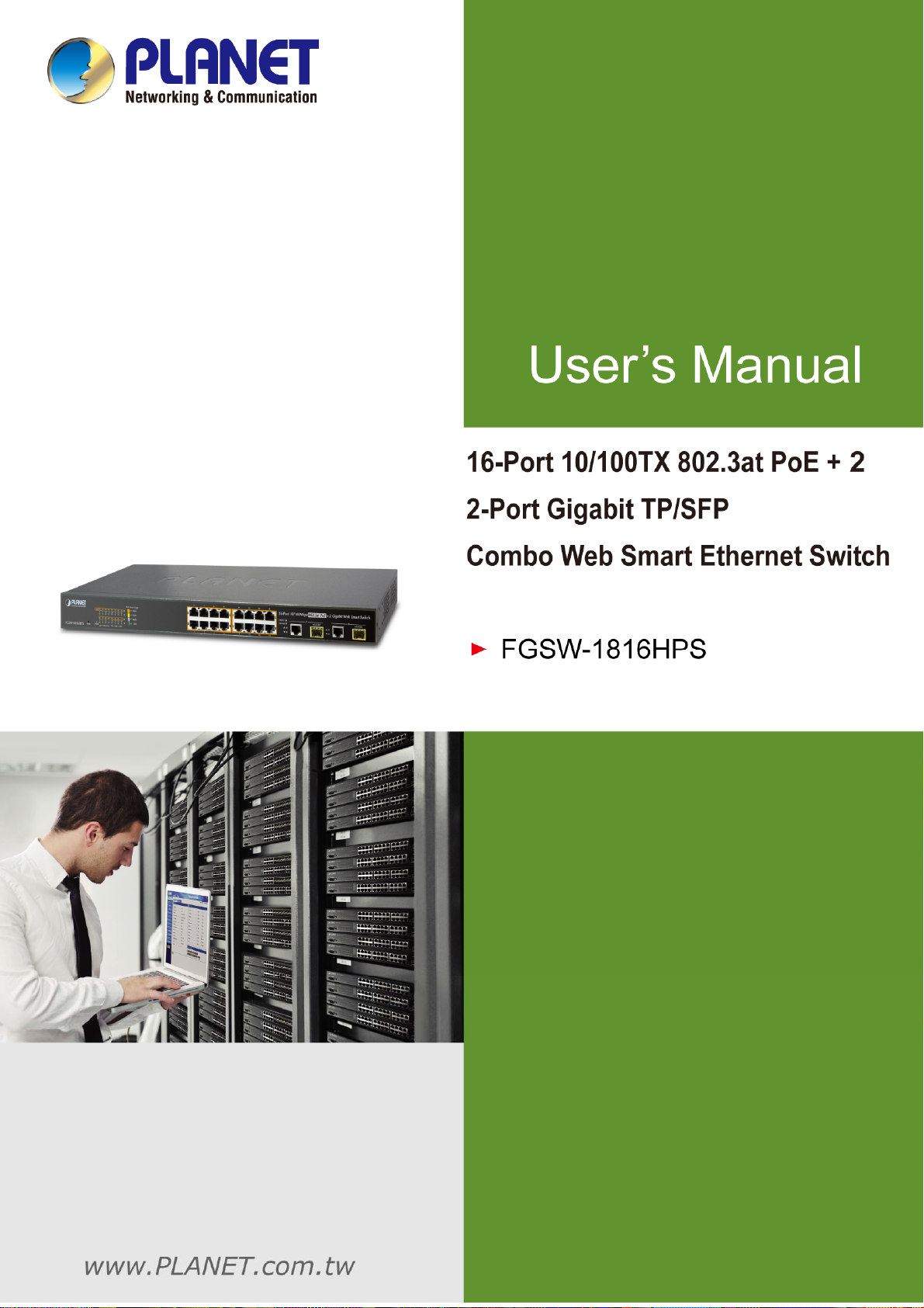
2.1.1 Switch Front Panel
The front panel provides a simple interface monitoring the PoE Web Smart Switch. Figure 2-1 shows the front panel of the
FGSW-1816HPS.
Front Panel
Figure 2-
■ Fast Ethernet TP interface
10/100Base-TX Copper, RJ-45 Twist-Pair: Up to 100 meters.
■ Gigabit TP Interface
Port-17, Port-18: 10/100/1000Base-T Copper, RJ-45 Twist-Pair: up to 100 meters.
■ Gigabit SFP Slots
Port-17, Port-18: 1000Base-SX/LX mini-GBIC slot, SFP (Small Factor Pluggable) transceiver module: From 550 meters
(Multi-mode fiber), up to 10/20/30/40/50/70/120 kilometers (Single-mode fiber).
■ Reset Button
On the left side of the front panel, the reset button is designed for rebooting the PoE Web Smart Switch without turning off
and on the power. The following is the summary table of Reset button functions:
Reset Button Pressed and Released Function
< 5 sec: System Reboot Reboot the PoE Web Smart Switch.
> 5 sec: Factory Default
1 FGSW-1816HPS front panel
Reset the PoE Web Smart Switch to Factory Default
configuration. The PoE Web Smart Switch will then reboot
and load the default settings as shown below:
Default Username: admin
Default Password: admin
Default IP address: 192.168.0.100
Subnet mask: 255.255.255.0
Default Gateway: 192.168.0.254
15
Page 16

User’s Manual of FGSW-1816HPS
2.1.2 LED Indications
The front panel LEDs indicate instant status of port links, data activity and system power, and help monitor and troubleshoot
when needed. Figure 2-2 shows the LED indications of these PoE Web Smart Switches.
LED Indication
Figure 2-2 FGSW-1816HPS LED panel
System
LED Color Function
PWR Green Lights to indicate that the Switch has power.
Per 10/100Mbps port with PoE interfaces (Port-1 to Port-16)
LED Color Function
LNK/ACT Green
PoE In-Use Orange
Per 10/100/1000Mbps RJ-45 Combo Interface (Port-17 to Port-18)
LED Color Function
LNK/ACT Green Blink: Indicates that the Switch is actively sending or receiving data over that port.
100/1000 Green
Per 1000Mbps SFP Combo Interface (Port-17 to Port-18)
LED Color Function
Lights: Indicates the link through that port is successfully established at 10/100Mbps.
Blink: Indicates that the Switch is actively sending or receiving data over that port.
Lights: Indicates the port is providing 56V DC in-line power.
Off: Indicates the connected device is not a PoE Powered Device (PD).
Lights. Indicates the port is successfully established at 1000Mbps.
Slow
Blink:
OFF: Indicates the port is successfully established at 10Mbps.
Indicates the port is successfully established at 100Mbps.
LNK/ACT Green Blink: Indicates that the Switch is actively sending or receiving data over that port.
1000 Green Lights. Indicates the port is successfully established at 1000Mbps.
PoE Usage
LED Color Function
50W Orange
100W Orange
150W Orange
190W Orange
Lights to indicate the PoE power consumption has equal 50W or over 50W.
Lights to indicate the PoE power consumption has equal 100W or over 100W.
Lights to indicate the PoE power consumption has equal 150W or over 150W.
Lights to indicate the PoE power consumption has equal 190W or over 190W.
16
Page 17

User’s Manual of FGSW-1816HPS
2.1.3 Switch Rear Panel
The rear panel of the PoE Web Smart Switch indicates a DC inlet power socket. Figure 2-3 shows the rear panel of these PoE
Web Smart Switches
Rear Panel
Figure 2-
■ AC Power Receptacle
For compatibility with electric service in most areas of the world, the PoE Web Smart Switch’s power supply automatically
adjusts to line power in the range of 100-240V AC and 50/60 Hz.
3 Rear panel of FGSW-1816HPS
Plug the female end of the power cord firmly into the receptalbe on the rear panel of the PoE Web Smart Switch. Plug the
other end of the power cord into an electric service outlet and the power will be ready.
The device is a power-required device, which means it will not work till it is powered. If your networks
should be active all the time, please consider using UPS (Uninterrupted Power Supply) for your device.
Power Notice:
It will prevent you from network data loss or network downtime. In some areas, installing a surge
suppression device may also help to protect your PoE Web Smart Switch from being damaged by
unregulated surge or current to the Switch or the power adapter.
17
Page 18

User’s Manual of FGSW-1816HPS
2.2 Installing the Switch
This section describes how to install your PoE Web Smart Switch and make connections to the PoE Web Smart Switch. Please
read the following topics and perform the procedures in the order being presented. To install your PoE Web Smart Switch on a
desktop or shelf, simply complete the following steps.
2.2.1 Desktop Installation
To install the PoE Web Smart Switch on desktop or shelf, please follow these steps:
Step1: Attach the rubber feet to the recessed areas on the bottom of the PoE Web Smart Switch.
Step2: Place the PoE Web Smart Switch on the desktop or the shelf near a DC or PoE-in power source, as shown in Figure 2-4.
Figure 2-4 Place the PoE W
Step3: Keep enough ventilation space between the PoE Web Smart Switch and the surrounding objects.
When choosing a location, please keep in mind the environmental restrictions discussed in Chapter 1,
Section 4 under specifications.
Step4: Connect the PoE Web Smart Switch to network devices.
Connect one end of a standard network cable to the 10/100/1000 RJ-45 ports on the front of the PoE Web Smart Switch.
Connect the other end of the cable to the network devices such as printer server, workstation or router.
Connection to the PoE Web Smart Switch requires UTP Category 5 network cabling with RJ-45 tips.
For more information, please see the Cabling Specifications in Appendix A.
eb Smart Switch on the desktop
Step5: Supply power to the PoE Web Smart Switch.
Connect one end of the power cable to the PoE Web Smart Switch.
Connect the power plug of the power cable to a standard wall outlet.
When the PoE Web Smart Switch receives power, the Power LED should remain solid Green.
18
Page 19

User’s Manual of FGSW-1816HPS
2.2.2 Rack Mounting
To install the PoE Web Smart Switch in a 19-inch standard rack, please follow the instructions described below.
Step1: Place the PoE Web Smart Switch on a hard flat surface, with the front panel positioned towards the front side.
Step2: Attach the rack-mount bracket to each side of the PoE Web Smart Switch with supplied screws attached to the package.
Figure 2-5 shows how to attach brackets to one side of the PoE Web Smart Switch.
Figure 2-5: Attach Brackets to the PoE Web Smart Switch.
You must use the screws supplied with the mounting brackets. Damage caused to the parts by
using incorrect screws would invalidate the warranty.
Step3: Secure the brackets tightly.
Step4: Follow the same steps to attach the second bracket to the opposite side.
Step5: After the brackets are attached to the PoE Web Smart Switch, use suitable screws to securely attach the brackets to the
rack, as shown in Figure 2-6.
ure 2-6: Mounting PoE Web Smart Switch in a Rack
Fig
19
Page 20

User’s Manual of FGSW-1816HPS
Step6: Proceeds with the steps 4 and 5 of session 2.2.1 Desktop Installation to connect the network cabling and supply power
to the PoE Web Smart Switch.
2.2.3 Installing the SFP transceiver
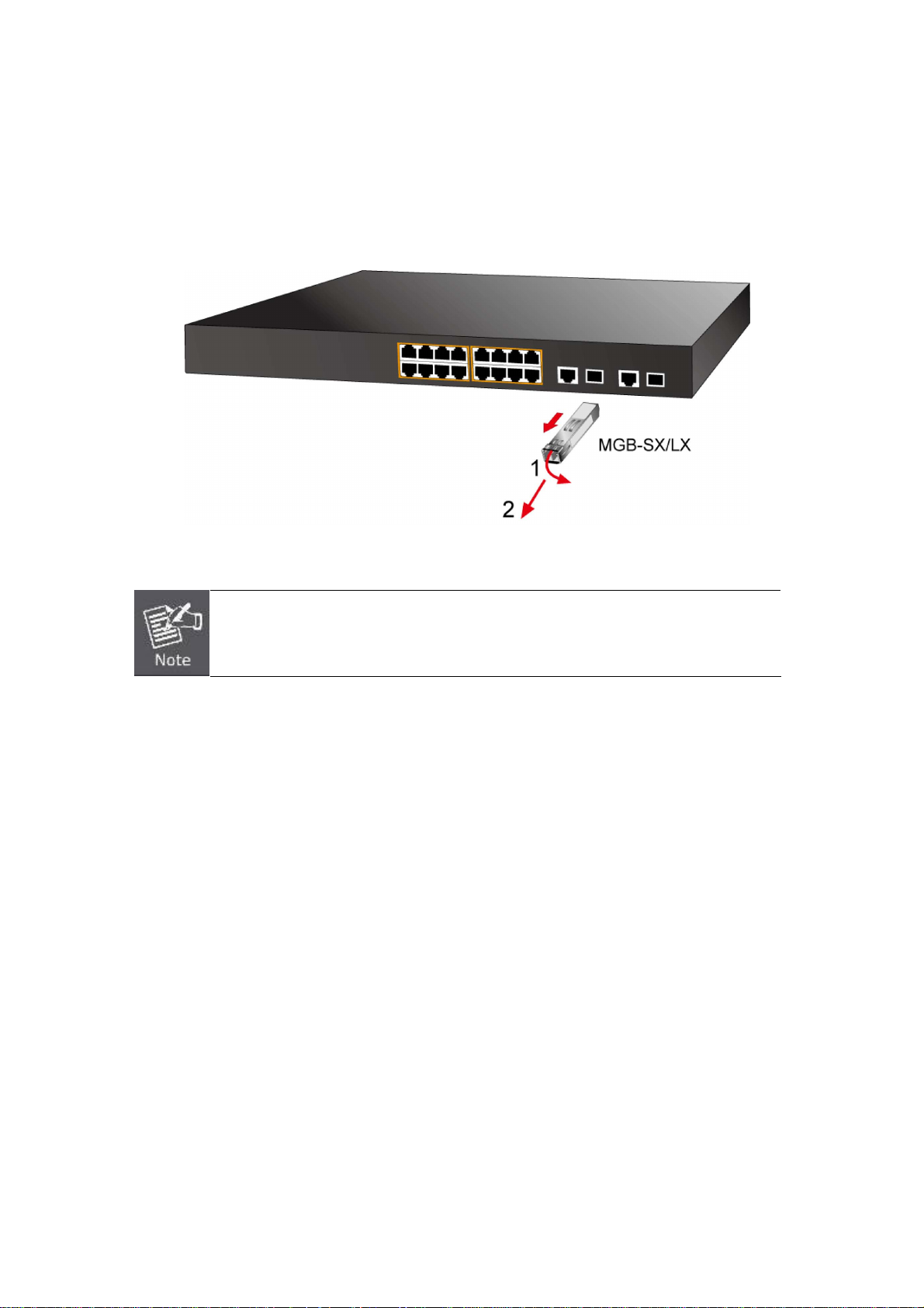
The sections describe how to insert an SFP transceiver into an SFP slot.
The SFP transceivers are hot-pluggable and hot-swappable. You can plug in and out the transceiver to/from any SFP port
without having to power down the PoE Web Smart Switch, as the Figure 2-5 shows.
Figure 2-5 Plug in the SFP transceiver
Approved PLANET SFP Transceivers
PLANET PoE Web Smart Switch supports both Single mode and Multi-mode SFP transceiver. The following list of approved
PLANET SFP transceivers is correct at the time of publication:
Gigabit Ethernet Transceiver (1000Base-X SFP)
Model Speed (Mbps)
MGB-GT 1000 Copper -- 100m --
MGB-SX 1000 LC Multi Mode 550m 850nm
MGB-SX2 1000 LC Multi Mode 2km 1310nm
MGB-LX 1000 LC Single Mode 10km 1310nm
MGB-L30 1000 LC Single Mode 30km 1310nm
MGB-L50 1000 LC Single Mode 50km 1550nm
MGB-L70 1000 LC Single Mode 70km 1550nm
Connector
Interface
Fiber Mode
Distance Wavelength (nm) Operating Temp.
0 ~ 60 ℃
0 ~ 60 ℃
0 ~ 60 ℃
0 ~ 60 ℃
0 ~ 60 ℃
0 ~ 60 ℃
0 ~ 60 ℃
MGB-L120 1000 LC Single Mode 120km 1550nm
MGB-TSX 1000 LC Multi Mode 550m 850nm
MGB-TLX 1000 LC Single Mode 10km 1310nm
MGB-TL30 1000 LC Single Mode 30km 1310nm
MGB-TL70 1000 LC Single Mode 70km 1550nm
20
0 ~ 60 ℃
-40 ~ 75 ℃
-40 ~ 75 ℃
-40 ~ 75 ℃
-40 ~ 75 ℃
Page 21

Gigabit Ethernet Transceiver (1000Base-BX, Single Fiber Bi-Directional SFP)
User’s Manual of FGSW-1816HPS
Model Speed (Mbps)
MGB-LA10 1000 WDM(LC) Single Mode 10km 1310nm 1550nm
MGB-LB10 1000 WDM(LC) Single Mode 10km 1550nm 1310nm
MGB-LA20 1000 WDM(LC) Single Mode 20km 1310nm 1550nm
MGB-LB20 1000 WDM(LC) Single Mode 20km 1550nm 1310nm
MGB-LA40 1000 WDM(LC) Single Mode 40km 1310nm 1550nm
MGB-LB40 1000 WDM(LC) Single Mode 40km 1550nm 1310nm
MGB-LA60 1000 WDM(LC) Single Mode 60km 1310nm 1550nm
MGB-LB60 1000 WDM(LC) Single Mode 60km 1550nm 1310nm
MGB-TLA10 1000 WDM(LC) Single Mode 10km 1310nm 1550nm
MGB-TLB10 1000 WDM(LC) Single Mode 10km 1550nm 1310nm
MGB-TLA20 1000 WDM(LC) Single Mode 20km 1310nm 1550nm
MGB-TLB20 1000 WDM(LC) Single Mode 20km 1550nm 1310nm
MGB-TLA40 1000 WDM(LC) Single Mode 40km 1310nm 1550nm
MGB-TLB40 1000 WDM(LC) Single Mode 40km 1550nm 1310nm
Connector
Interface
Fiber Mode Distance Wavelength (TX) Wavelength (RX) Operating Temp.
0 ~ 60 ℃
0 ~ 60 ℃
0 ~ 60 ℃
0 ~ 60 ℃
0 ~ 60 ℃
0 ~ 60 ℃
0 ~ 60 ℃
0 ~ 60 ℃
-40 ~ 75 ℃
-40 ~ 75 ℃
-40 ~ 75 ℃
-40 ~ 75 ℃
-40 ~ 75 ℃
-40 ~ 75 ℃
MGB-TLA60 1000 WDM(LC) Single Mode 60km 1310nm 1550nm
MGB-TLB60 1000 WDM(LC) Single Mode 60km 1550nm 1310nm
-40 ~ 75 ℃
-40 ~ 75 ℃
It is recommended to use PLANET SFP on the PoE Web Smart Switch. If you insert an SFP
transceiver that is not supported, the PoE Web Smart Switch will not recognize it.
1. Before we connect PoE Web Smart Switch to the other network device, we have to make sure both sides of the SFP
transceivers are with the same media type, for example: 1000Base-SX to 1000Base-SX, 1000Bas-LX to 1000Base-LX.
2. Check whether the fiber-optic cable type matches with the SFP transceiver requirement.
To connect to 1000Base-SX SFP transceiver, please use the multi-mode fiber cable with one side being the male
duplex LC connector type.
To connect to 1000Base-LX SFP transceiver, please use the single-mode fiber cable with one side being the male
duplex LC connector type.
Connect the Fiber Cable
1. Insert the duplex LC connector into the SFP transceiver.
2. Connect the other end of the cable to a device with SFP transceiver installed.
3. Check the LNK/ACT LED of the SFP slot on the front of the PoE Web Smart Switch. Ensure that the SFP transceiver is
operating correctly.
4. Check the Link mode of the SFP port if the link fails. To function with some fiber-NICs or Media Converters, user has to set
the port Link mode to “1000 Force”.
21
Page 22
Remove the Transceiver Module
1. Make sure there is no network activity anymore.
2. Remove the Fiber-Optic Cable gently.
3. Lift up the lever of the MGB module and turn it to a horizontal position.
4. Pull out the module gently through the lever.
User’s Manual of FGSW-1816HPS
Figure 2-
Never pull out the module without lifting up the lever of the module and turning it to a
horizontal position. Directly pulling out the module could damage the module and the SFP
module slot of the PoE Web Smart Switch.
8 How to Pull Out the SFP Transceiver
22
Page 23

User’s Manual of FGSW-1816HPS
3. SWITCH MANAGEMENT
This chapter explains the methods that you can use to configure management access to the PoE Web Smart Switch. It
describes the types of management applications and the communication and management protocols that deliver data between
your management device (workstation or personal computer) and the system. It also contains information about port connection
options.
This chapter covers the following topics:
Requirements
Management Access Overview
Web Management Access
SNMP Access
Standards, Protocols, and Related Readings
3.1 Requirements
Workstations running Windows 2000/XP, 2003, Vista/7/8, 2008, MAC OS9 or later, Linux, UNIX or other platforms
are compatible with TCP/IP protocols.
Workstation is installed with Ethernet NIC (Network Interface Card)
Ethernet Port connection
Network cables -- Use standard network (UTP) cables with RJ45 connectors.
The above Workstation is installed with Web Browser and JAVA runtime environment Plug-in
It is recommended to use Internet Explore 8.0 or above to access PoE Web Smart Switch.
23
Page 24

User’s Manual of FGSW-1816HPS
3.2 Management Access Overview
The PoE Web Smart Switch gives you the flexibility to access and manage it using any or all of the following methods:
Web browser interface
An external SNMP-based network management application
The Web browser management is embedded in the PoE Web Smart Switch software and available for immediate use. Each of
these management methods has their own advantages. Table 3-1 compares the three management methods.
Method Advantages Disadvantages
Web Browser
SNMP Agent
Ideal for configuring the switch
remotely
Compatible with all popular
browsers
Can be accessed from any location
Most visually appealing
Communicates with switch functions
at the MIB level
Based on open standards
3.3 Web Management
Security can be compromised (hackers
need to know only the IP address and
subnet mask)
May encounter lag times on poor
connections
Requires SNMP manager software
Least visually appealing of all three
methods
Some settings require calculations
Security can be compromised (hackers
need to know only the community name)
Table 3-1 Comparison of Management Methods
The PoE Web Smart Switch offers management features that allow users to manage the PoE Web Smart Switch from anywhere
on the network through a standard browser such as Microsoft Internet Explorer. After you set up your IP address for the switch,
you can access the PoE Web Smart Switch's Web interface applications directly in your Web browser by entering the IP address
of the PoE Web Smart Switch.
Figure 3-1 Web Management
24
Page 25

User’s Manual of FGSW-1816HPS
You can then use your Web browser to list and manage the PoE Web Smart Switch configuration parameters from one central
location, just as if you were directly connected to the PoE Web Smart Switch's console port. Web Management requires either
Microsoft Internet Explorer 8.0 or later, Google Chrome, Safari or Mozilla Firefox 1.5 or later.
Figure 3-2 Web Main Screen of the PoE Web Smart Switch
3.4 SNMP-based Network Management
You can use an external SNMP-based application to configure and manage the PoE Web Smart Switch, such as SNMPc
Network Manager, HP Openview Network Node Management (NNM) or What’s Up Gold. This management method requires
the SNMP agent on the switch and the SNMP Network Management Station to use the same community string. This
management method, in fact, uses two community strings: the get community string and the set community string. If the
SNMP Network Management Station only knows the set community string, it can read and write to the MIBs. However, if it only
knows the get community string, it can only read MIBs. The default get and set community strings for the PoE Web Smart
Switch are public.
Figure 3-4 SNMP Management
25
Page 26

User’s Manual of FGSW-1816HPS
4. WEB CONFIGURATION
This section introduces the configuration and functions of the Web-based management.
About Web-based Management
The PoE Web Smart Switch offers management features that allow users to manage the PoE Web Smart Switch from anywhere
on the network through a standard browser such as Microsoft Internet Explorer.
The Web-based Management supports Internet Explorer 8.0. It is based on Java Applets with an aim to reduce network
bandwidth consumption, enhance access speed and present an easy viewing screen.
By default, IE8.0 or later version does not allow Java Applets to open sockets. The user has to
explicitly modify the browser setting to enable Java Applets to use network ports.
The PoE Web Smart Switch can be configured through an Ethernet connection, making sure the manager PC must be set on
the same IP subnet address as the PoE Web Smart Switch.
For example, the default IP address of the PoE Web Smart Switch is 192.168.0.100, then the manager PC should be set at
192.168.0.x (where x is a number between 1 and 254, except 100), and the default subnet mask is 255.255.255.0.
If you have changed the default IP address of the PoE Web Smart Switch to 192.168.1.1 with subnet mask 255.255.255.0 via
console, then the manager PC should be set at 192.168.1.x (where x is a number between 2 and 254) to do the relative
configuration on manager PC.
Figure 4-1 Web Management
Logging on the switch
1. Use Internet Explorer 8.0 or above Web browser. Enter the factory-default IP address to access the Web interface. The
factory default IP Address is as follows:
http://192.168.0.100
26
Page 27

User’s Manual of FGSW-1816HPS
2. When the following login screen appears, please enter "admin" as the default username and “admin” as the password
(unless you have changed these, in which case use your own login details) to log in the main screen of the PoE Web
Smart Switch. The login screen in Figure 4-1-2 appears.
Figure 4-2 Login Screen
Default User Name: admin
Default Password: admin
After entering the username and password, the main screen appears as Figure 4-1-3.
Figure 4-3 Default Main Page
Now, you can use the Web management interface to continue the switch management or manage the PoE Web Smart Switch
by Web interface. The Switch Menu on the left of the web page let you access all the commands and statistics the PoE Web
Smart Switch provides.
For security reason, please change and memorize the new password after this first setup.
Only accept command in lowercase letter under web interface.
27
Page 28

User’s Manual of FGSW-1816HPS
4.1 Main Web Page
The PoE Web Smart Switch provides a Web-based browser interface for configuring and managing it. This interface allows you
to access the PoE Web Smart Switch using the Web browser of your choice. This chapter describes how to use the PoE Web
Smart Switch’s Web browser interface to configure and manage it.
Main Functions Menu
Main Screen
Copper Port Link Status
SFP Port Link Status
Figure 4-1-1 Main Page
Panel Display
The web agent displays an image of the PoE Web Smart Switch’s ports. The Mode can be set to display different information for
the ports, including Link up or Link down. Clicking on the image of a port opens the Port Statistics page.
The port statuses are illustrated as follows:
Status Down Link
RJ-45 Ports
SFP Ports
Main Menu
Using the onboard web agent, you can define system parameters, manage and control the PoE Web Smart Switch, and all its
ports, or monitor network conditions. Via the Web-Management, the administrator can set up the PoE Web Smart Switch by
selecting the functions those listed in the Main Function. The screen in Figure 4-1-5 appears.
28
 Loading...