

Page 1

8-Port 10/100Mbps + 2- Gigabit TP/SFP
Managed Switch
FGSD-1022 / FGSD-1022P
Quick Installation Guide
Page 2

Table of Contents
1. Package Content .......................................................................................... 3
2. Requirements .............................................................................................. 4
3. Terminal Setup ............................................................................................ 5
4. Logon to the Console ................................................................................... 6
5. Congure IP address .................................................................................... 7
6. Start Web Management ................................................................................ 9
7. While IP Address be changed or forgotten admin password – ........................11
8. Customer Support .....................................................................................12
Page 3

1. Package Content
Thank you for purchasing PLANET 8-Port Fast Ethernet + 2-Port Gigabit TP/SFP
Combo Managed Switch, FGSD-1022 and FGSD-1022P. Terms of “Managed Switch”
means the switches mentioned titled in the cover page of this Quick Installation
Guide.
Upon open the box of the Managed Switch and carefully unpack it. The box should
contain the following items:
● The Managed Switch x 1
● This Quick Installation Guide x 1
● User’s Manual CD x 1
● Power Cord x 1
● Rubber Feet x 4
● Two Rack-mounting Brackets with Attachment Screws x 1
● RS-232 DB9 Male Console Cable
If any item is found missing or damaged, please contact your local reseller for
replacement.
3
Page 4
4
2. Requirements
Note
The Managed Switch provide remote Web interface for manage; the following
equipments are necessary for further management.
n Workstation installed with Ethernet NIC (Network Interface Card)
n Workstations of subscribers running Windows 98/ME, NT4.0, 2000/XP, Vista, MAC
OS9 or later, Linux, UNIX or other platform compatible with TCP/IP protocols.
n Ethernet Port connect
• Network cables - use standard network (UTP) cables with RJ45 connectors
• Above Workstation installed with WEB Browser and JAVA runtime environment
Plug-in
n Serial Port connect
• Above PC with COM Port (DB-9 / RS-232) or USB-to-RS-232 converter
It is recommended to use Internet Explore 6.0 or above to access
the Managed Switch.
Page 5

3. Terminal Setup
PC / Workstation
with
Terminal emulation software
Managed Switch
Serial Port
Serial Port
57600,8,n,1
RS-232
To congure the system, connect a serial cable to a COM port on a PC or
notebook computer and to serial (console) port of the Managed. The console port
of the Managed Switch is DCE already, so that you can connect the console port
directly through PC without the need of Null Modem.
Figure 3-1 Serial / Console connection
A terminal program is required to make the software connection to the Managed
Switch. Windows’ Hyper Terminal program may be a good choice. The Hyper
Terminal can be accessed from the Start menu.
1. Click
2. When the following screen appears, make sure that the COM port should be
START, then Programs, Accessories and then Hyper Terminal.
congured as:
u Baud : 57600
u Parity : None
u Data bits : 8
u Stop bits : 1
u Flow Control : None
Figure 3-2 Hyper Terminal Setting
5
Page 6

6
4. Logon to the Console
Note
Once the terminal has connected to the device, power on the Managed Switch, the
terminal will display that it is running testing procedures.
Then, the following message asks the login user name and password. The factory
default password as following and the login screen in Figure 4-1 appears.
User name: admin
Password: admin
Figure 4-1 Managed Switch Console Login screen
1. For security reason, please change and memorize the new password after this first setup.
2. Only accept command in lowercase letter under console interface.
Page 7

5. Congure IP address
The Managed Switch is shipped with default IP address as following.
IP Address : 192.168.0.100
Subnet Mask : 255.255.255.0
To check the current IP address or modify a new IP address for the Switch, please
use the procedures as follow:
n Show the current IP address
1. On “Switch#” prompt, enter “congure”.
“Switch(cong)#” prompt, enter “show ip”.
2. On
3. The screen displays the current IP address, Subnet Mask and Gateway. As show
in Figure 5-1.
Figure 5-1 Show IP Information screen
n Congure IP address and Default Gateway
4. On “Switch(cong)#” prompt, enter the following command and press
<Enter>. As show in Figure 5-2.
Switch(cong)# ip address 192.168.1.100 255.255.255.0 192.168.1.1
Switch(Cong)# ip default-gateway 192.168.1.254
7
Page 8

8
The previous command would apply the follow settings for the Switch.
Note
IP: 192.168.1.100
Subnet Mask: 255.255.255.0
Gateway: 192.168.1.1
Figure 5-2 Set IP address screen
5. Repeat Step 1 to check if the IP address is changed.
n Store current switch conguration
6. On “Switch(cong)#” prompt, enter the following command and press
<Enter>.
Switch(cong)# copy running-cong startup-cong
If the IP is successfully congured, the Managed Switch will apply the new IP
address setting immediately. You can access the Web interface of the Managed
Switch through the new IP address.
If you do not familiar with console command or the related parameter, enter “help” anytime in console to get the help description.
Page 9
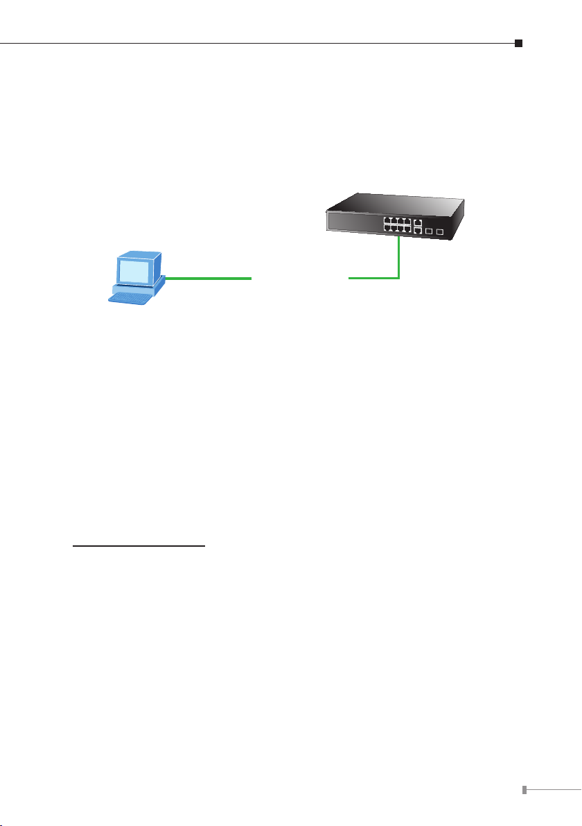
6. Start Web Management
192.168.0.x
PC / Workstation
with
IE Brower
RJ-45/UTP-Cable
Managed Switch
IP Adress:
192.168.0.100
IP Adress:
The Managed Switch provides a built-in browser interface. You can manage it
remotely by having a remote host with Web browser, such as Microsoft Internet
Explorer, Netscape Navigator or Mozilla Firefox.
Figure 6-1 IP Management Diagram
The following shows how to startup the Web Management of the Managed Switch,
please note the Managed Switch is congured through an Ethernet connection,
make sure the manager PC must be set on the same IP subnet address.
For example, the default IP address of the Managed Switch is 192.168.0.100 (the
factory-default IP address), then the manager PC should be set at 192.168.0.x
(where x is a number between 1 and 254, except 100), and the default subnet
mask is 255.255.255.0.
Login the Managed Switch
1. Use Internet Explorer 6.0 or above Web browser, enter IP address
http://192.168.0.100 (the factory-default IP address or that you have just
changed in console) to access the Web interface.
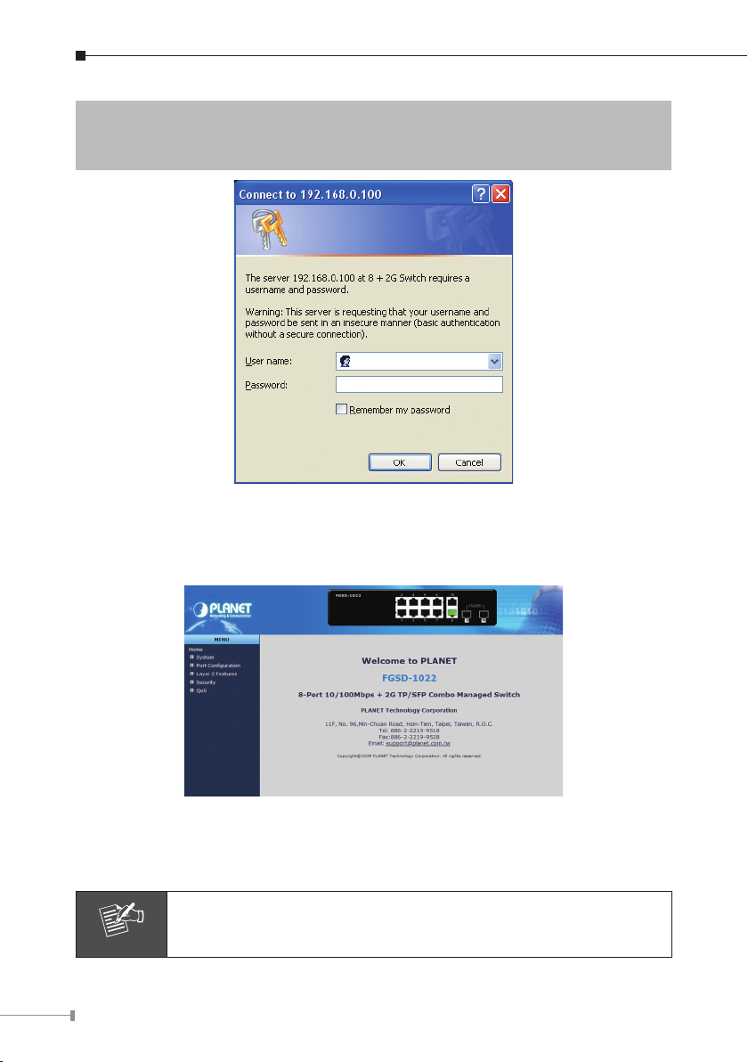
2. When the following dialog box appears, please enter the default user name
“admin” and password “admin”. The login screen in Figure 6-2 appears. In
the following we use FSD-1022 as the example, yet it is same settings for both
Managed Switch model in this guide.
9
Page 10
10
Default IP Address: 192.168.0.100
Note
Default User name: admin
Default Password: admin
Figure 6-2 Web Login Screen of FGSD-1022
3. After entering the user name and password, the Web main screen appears as
Figure 6-3.
Figure 6-3 Web Main Screen of FGSD-1022 series Managed Switch
Now, you can use the Web management interface to continue the Managed Switch
management, please refer to the user manual for more.
For security reason, please change and memorize the new password after this first setup.
Page 11
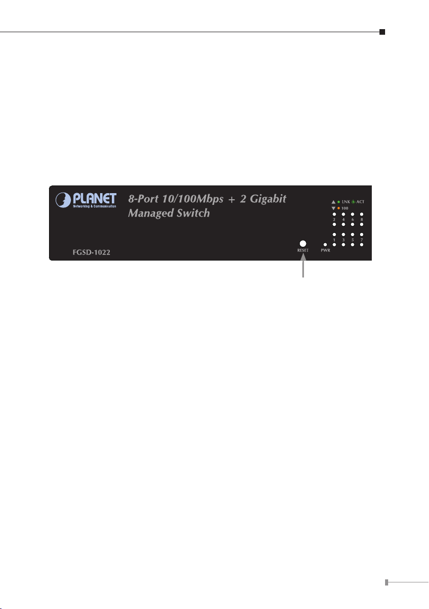
7. While IP Address be changed or forgotten admin
Hardware Reset
password –
To reset the IP address to the default IP Address “192.168.0.100” and the user
name / password to factory default mode (default user name and password are
both admin). Press the hardware reset button at the front panel about 5 seconds.
After the device is rebooted, you can login the management Web interface within
the same subnet of 192.168.0.xx and default user name / password. Be noted, all
the previous setup will disappeared after factory reset.
11
Page 12

8. Customer Support
Thank you for purchase PLANET products. You can browse our online FAQ resource
at the PLANET Web site rst to check if it could solve you issue. If you need more
support information, please contact PLANET switch support team.
PLANET online FAQ :
http://www.planet.com.tw/en/support/faq.php?type=1
Switch support team mail address :
support_switch@planet.com.tw
Copyright © PLANET Technology Corp. 2010.
Contents subject to revision without prior notice.
PLANET is a registered trademark of PLANET Technology Corp. All other trademarks
belong to their respective owners.
12
 Loading...