

Page 1
User’s Manual of EPL-2000
1
Page 2

User’s Manual of EPL-2000
Trademarks
Copyright © PLANET Technology Corp. 2014.
Contents are subject to revision without prior notice.
PLANET is a registered trademark of PLANET Technology Corp. All other trademarks belong to their respective owners.
Disclaimer
PLANET Technology does not warrant that the hardware will work properly in all environments and applications, and makes no
warranty and representation, either implied or expressed, with respect to the quality, performance, merchantability, or fitness for
a particular purpose. PLANET has made every effort to ensure that this User's Manual is accurate; PLANET disclaims liability
for any inaccuracies or omissions that may have occurred.
Information in this User's Manual is subject to change without notice and does not represent a commitment on the part of
PLANET. PLANET assumes no responsibility for any inaccuracies that may be contained in this User's Manual. PLANET makes
no commitment to update or keep current the information in this User's Manual, and reserves the right to make improvements to
this User's Manual and/or to the products described in this User's Manual at any time without notice.
If you find information in this manual that is incorrect, misleading, or incomplete, we would appreciate your comments and
suggestions.
FCC Warning
This equipment has been tested and found to comply with the limits for a Class A digital device, pursuant to Part 15 of the FCC
Rules. These limits are designed to provide reasonable protection against harmful interference when the equipment is operated
in a commercial environment. This equipment generates, uses, and can radiate radio frequency energy and, if not installed and
used in accordance with the Instruction manual, may cause harmful interference to radio communications. Operation of this
equipment in a residential area is likely to cause harmful interference in which case the user will be required to correct the
interference at whose own expense.
CE Mark Warning
This is a Class A product. In a domestic environment, this product may cause radio interference, in which case the user may be
required to take adequate measures.
Energy Saving Note of the Device
This power required device does not support Standby mode operation. For energy saving, please remove the power cable to
disconnect the device from the power circuit. Without removing power cable, the device will still consume power from the power
source. In view of Saving the Energy and reducing the unnecessary power consumption, it is strongly suggested to remove the
power connection for the device if this device is not intended to be active.
WEEE Warning
To avoid the potential effects on the environment and human health as a result of the presence of hazardous
substances in electrical and electronic equipment, end users of electrical and electronic equipment should
understand the meaning of the crossed-out wheeled bin symbol. Do not dispose of WEEE as unsorted
municipal waste and have to collect such WEEE separately. ecember
Revision
PLANET GEPON OLT (2-PON Interface, 2 x GbE SFP, 1 x MGT Port) User’s manual
MODEL: EPL-2000
REVISION: 1.2 (December, 2014)
Part No.: EM-EPL-2000 (2081-BA0080-002)
2
Page 3

User’s Manual of EPL-2000
TABLE OF CONTENTS
1. INTRODUCTION....................................................................................................................5
1.1 Packet Contents...........................................................................................................................................5
1.2 Product Description.....................................................................................................................................6
1.3 How to Use This Manual..............................................................................................................................7
1.4 Product Features..........................................................................................................................................7
1.5 Product Specifications ................................................................................................................................9
2. HARDWARE INSTALLATION .............................................................................................10
2.1 Hardware Description................................................................................................................................10
2.1.1 OLT Front Panel ..................................................................................................................................................10
2.1.2 LED Indications ...................................................................................................................................................11
2.1.3 OLT Rear Panel ...................................................................................................................................................12
2.2 Installing the OLT .......................................................................................................................................12
2.2.1 Rack Mounting.....................................................................................................................................................12
2.2.2 Installing the SFP Transceiver .............................................................................................................................14
3. MANAGEMENT SOFTWARE INSTALLATION...................................................................16
3.1 Requirements..............................................................................................................................................16
3.2 Management Access Overvi ew.................................................................................................................17
3.3 EMS Utility Management............................................................................................................................17
3.3.1 MySQL Server Installation ...................................................................................................................................18
3.3.2 EMS Utility Installation .........................................................................................................................................27
3.3.3 Starting PLANET EMS Management...................................................................................................................29
3.4 SNMP-based Network Management.........................................................................................................30
4. EMS Management System................................................................................................. 31
4.1 EMS Toolbar................................................................................................................................................32
4.1.1 System:................................................................................................................................................................32
4.1.2 Alarm: ..................................................................................................................................................................35
4.1.3 Config ..................................................................................................................................................................39
4.1.4 Performance ........................................................................................................................................................40
4.1.5 Help .....................................................................................................................................................................40
4.2 OLT Management........................................................................................................................................42
4.2.1 System Basic Information ....................................................................................................................................44
3
Page 4

User’s Manual of EPL-2000
4.2.2 Basic Information.................................................................................................................................................45
4.2.3 Net Interface Management ..................................................................................................................................46
4.2.4 User Management ...............................................................................................................................................47
4.2.5 IGMPSetting ........................................................................................................................................................48
4.2.6 Trunk Management..............................................................................................................................................49
4.2.7 VLAN Management .............................................................................................................................................50
4.2.8 IPTV Profile .........................................................................................................................................................56
4.2.9 IPTV Channel ...................................................................................................................................................... 56
4.2.10 Port Property .....................................................................................................................................................57
4.2.11 Port Status .........................................................................................................................................................60
4.3 PON Card Management .............................................................................................................................61
4.3.1 Interface Information............................................................................................................................................61
4.3.2 OLT Global Setting ..............................................................................................................................................63
4.3.3 ONU Auth ............................................................................................................................................................64
4.4 ONU Management ......................................................................................................................................65
4.4.1 Basic Configuration .............................................................................................................................................66
4.4.2 Global Parameter ................................................................................................................................................67
4.4.3 ONU Multicast Group ..........................................................................................................................................68
4.4.4 ONU Port Management .......................................................................................................................................68
4.4.5 Port Multicast.......................................................................................................................................................70
4.4.6 ONU VLAN ..........................................................................................................................................................70
4.4.7 Port Policying.......................................................................................................................................................72
4.4.8 Port Egress..........................................................................................................................................................73
4.5 How to upgrade EPL-2000 firmware.........................................................................................................74
5. EPL-2000 OPERATION ....................................................................................................... 78
5.1 Address Table.............................................................................................................................................78
5.2 Learning ......................................................................................................................................................78
5.3 Forwarding & Filtering...............................................................................................................................78
5.4 Auto-Negotiation ........................................................................................................................................78
APPENDIX A ........................................................................................................................... 79
A.1 Switch's RJ45 Pin Assignments...............................................................................................................79
A.2 10/100Mbps, 10/100BASE-TX....................................................................................................................79
4
Page 5

User’s Manual of EPL-2000
1. INTRODUCTION
PLANET GEPON OLT – EPL-2000 – is GEPON Optical Line Terminal (OLT), consisting of two GEPON ports, two Gigabit SFP
Interfaces and one management port. The term “GEPON OLT” refers to the OLT in this user’s manual.
1.1 Packet Contents
The box should contain the following items:
GEPON OLT
MGB-PX20 SFP Transceivers
Quick Installation Guide
19” Rack Mount Accessory Kit
AC Power Cord
If any of these are missing or damaged, please contact your dealer immediately; if possible, retain the carton including the
original packing material, and use them again to repack the product in case there is a need to return it to us for repair.
x 1
x 2
x 1
x 1
x 1
5
Page 6
User’s Manual of EPL-2000
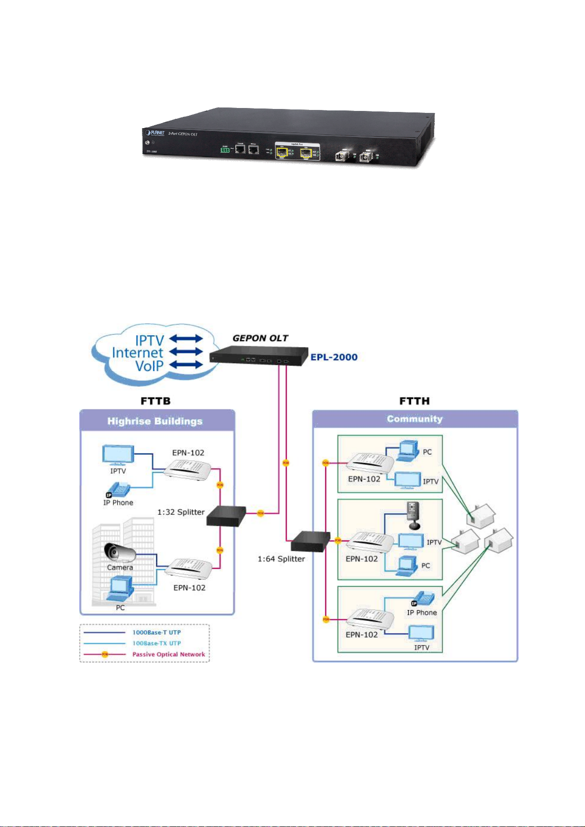
1.2 Product Description
Perfectly Designed for FTTx Applications
PLANET EPL-2000 is a GEPON Optical Line Terminal (OLT), consisting of two GEPON ports, two Gigabit SFP Interfaces and
one management port. It is easy to install and maintain the GEPON deployment. Working with PLANET GEPON Optical
Network Units (ONU) EPN series, PLANET EPL-2000 can provide highly-effective GEPON solutions and convenient
management for broadband network. PLANET GEPON technology provides a high bandwidth of up to 1.25Gbps for both
upstream and downstream, long-distance coverage of up to 20km between equipment nodes, and scalability and flexibility in
network deployment. It is a cost-effective access technology with reliable and scalable network for Triple-play service
applications.
High-speed Connectivity for ISP / Triple Play Devices
With the growing network services such as HDTV, IPTV, voice-over-IP (VoIP) and multimedia broadband applications, the
demand for broadband increases quickly. The present broadband environment has not met the market needs; however,
Passive Optical Network (PON) would be the most promising NGN (Next Generation Networking) technology to fulfill the
demand.
6
Page 7

User’s Manual of EPL-2000
Robust Lay
With a high-split ratio of 1:64 and supporting the usage of PLANET ONUs, the EPL-2000 can minimize the investment cost for
carriers. By using the advanced technology in the telecommunication industry, the EPL-2000 provides strong functionalities for
Ethernet features such as VLAN, Multicast, DBA (Dynamic Bandwidth Allocation), and Access Control List. The EPL-2000 is an
ideal solution for FTTx applications.
GEPON is a point to multipoint communications protocol based on Gigabit Ethernet. It allows a Gigabit Ethernet
communications fiber to be shared by multiple end users using a passive optical splitter. GEPON communication takes place
between an Optical Line Terminal (OLT) and multiple Optical Network Units (ONUs). Using standard terminology, downstream
traffic flows from OLT to ONU, and upstream traffic flows from ONU to OLT. A protocol called Multi Point Control Protocol (MPCP)
is used to arbitrate the channel between the ONU’s so that no collisions will occur on the common fiber.
er 2 Features
1.3 How to Use This Manual
This User Manual is structured as follows:
Section 2, Hardware INSTALLATION
The section explains the functions of the Switch and how to physically install the GEPON OLT.
Section 3, EMS Utility INSTALLATION
The section contains the information about how to install EMS Utility.
Section 4, EMS Utility CONFIGURATION
The section explains how to manage the GEPON OLT by EMS Utility.
Section 5, SWITCH OPERATION
The chapter explains how to do the switch operation of the GEPON OLT.
Appendix A
The section contains cable information of the GEPON OLT.
1.4 Product Features
GEPON Port
2 x SC type GEPON OLT port
Up to 1.25Gbps for upstream and downstream speed
Maximum transfer distance of up to 20km
Each OLT port supports up to 64 ONUs
Fully compliant with IEEE 802.3ah
Point-to-multipoint network topology
LED indicators for link status
Uplink and Management Port
2 x 1000BASE-SX/LX SFP Interface
Maximum transfer distance of up to 120km
1 x 10/100BASE-TX RJ45 management port
7
Page 8

Layer 2 Features
Dynamic bandwidth allocation (DBA) support
Supports VLAN
Supports up to 8K MAC Address Table
Enhanced IGMP features
Supports Link Aggregation on two uplink ports
OLT Management
User-friendly GUI Management
IPTV multicast creation and management
Up to 32 OLTs management through single GUI
SNMP v1 / v2c monitoring
Three users levels control
2 control interfaces
User’s Manual of EPL-2000
- IEEE 802.1Q tagged VLAN
- Up to 255 VLAN groups, out of 4094 VLAN ID
- Out-of-band IP via the Management RJ45 port
Supports ONU authentication; averts illegal ONUs access to network
Event message logging to system log
SNMP trap for alarm notification
ONU Management
ONU Port control
ONU Multicast control
ONU IGMP fastleave
ONU VLAN mode
- In-band IP via the two uplink ports
8
Page 9

1.5 Product Specifications
Product EPL-2000
Hardware Specifications
User’s Manual of EPL-2000
Transmission Speed
Optical Split Ratio
Uplink Port
Port
LED Indicators
EMS Utility Specifications
Switch Feature
Management
PON Port
MGMT Port
Downstream: 1.25 Gbps
Upstream: 1.25 Gbps
Up to 1:64
2 x 1000BASE-X SFP slot
2 x PON Port
1 x RJ45 (10/100BASE-TX)
1 x Power LED
1 x System LED
4 x Uplink Port LED (ACT and Link)
2 x PON LED (Link)
IPTV multicast creation and management
MAC address learning and binding
MAC filtering
Supports IGMP mode
Supports the VLAN division on the basis of port
Up to 4094 VLAN support
8K MAC Addresses support
ONU Multicast control
ONU IGMP fastleave
ONU VLAN mode
ONU Port Management
User-friendly GUI Utility
Firmware and Configuration upgradeable via Utility
Remote ONU Management
Standards Conformance
Safety FCC Part 15 Class A, CE
IEEE 802.3 10BASE-T
IEEE 802.3u 100BASE-TX
Standards Compliance
Environment Specifications
Dimensions (W x D x H)
Weight
Power
Temperature
Humidity
IEEE 802.3z Gigabit SX/LX
IEEE 802.3x Flow Control and Back pressure
IEEE 802.1Q VLAN Tagging
441 x 206 x 44mm
2.31kg
100 – 250V AC
Operating temperature: 0 ~ 50 degrees C
Storage temperature: -30 ~ 60 degrees C
Operating Humidity: 10 ~ 90% non-condensing
Storage Humidity: 5 ~ 95% non-condensing
9
Page 10
User’s Manual of EPL-2000
2. HARDWARE INSTALLATION
This section describes the hardware features and installation of the GEPON OLT on the desktop or rack mount. For easier
management and control of the GEPON OLT, familiarize yourself with its display indicators and ports. Front panel illustrations in
this chapter display the unit LED indicators. Before connecting any network device to the GEPON OLT, please read this chapter
completely.
2.1 Hardware Description
2.1.1 OLT Front Panel
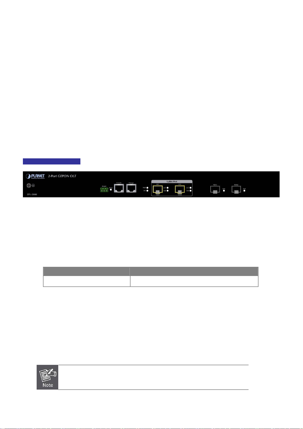
The unit front panel provides a simple interface monitoring the OLT. Figure 2-1 shows the front panel of the GEPON OLT.
EPL-2000 Front Panel
Figure 2-1 EPL-2000 Front Panel
■ RS-485 and RJ45 Console Connector
This is just for Manufacturer Technical Use
■ Reset Button
The reset button is designed for rebooting the GEPON OLT without turning off and on the power. The following is the
summary table of reset button functions:
Reset Button Pressed and Released Function
System reboot Reboot the GEPON OLT
■ Management Port
10/100BASE-TX Copper, RJ45 Twisted-[pair: Up to 100 meters
■ Gigabit SFP Uplink Slots
1000BASE-SX/LX mini-GBIC slot, SFP (Small Form Factor Pluggable) transceiver module: From 550 meters (multi-mode
fiber), up to 10/30/50/70/120 kilometers (single-mode fiber).
GE1 & GE2 Gigabit SFP uplink slots support 1000Mbps Forced Mode only. The remote
Gigabit switch or media converter’s SFP port must support 1000Mbps Forced Mode as well.
10
Page 11
User’s Manual of EPL-2000
■ Gigabit SFP PON Slots
1000BASE-PX20 mini-GBIC slot, SFP (Small Form Factor Pluggable) transceiver module: up to 20 kilometers
(single-mode fiber).
2.1.2 LED Indications
The front panel LEDs indicate instant status of port links, data activity and system power and help to monitor and troubleshoot
when needed. Figure 2-2 shows the LED indications of these GEPON OLTs.
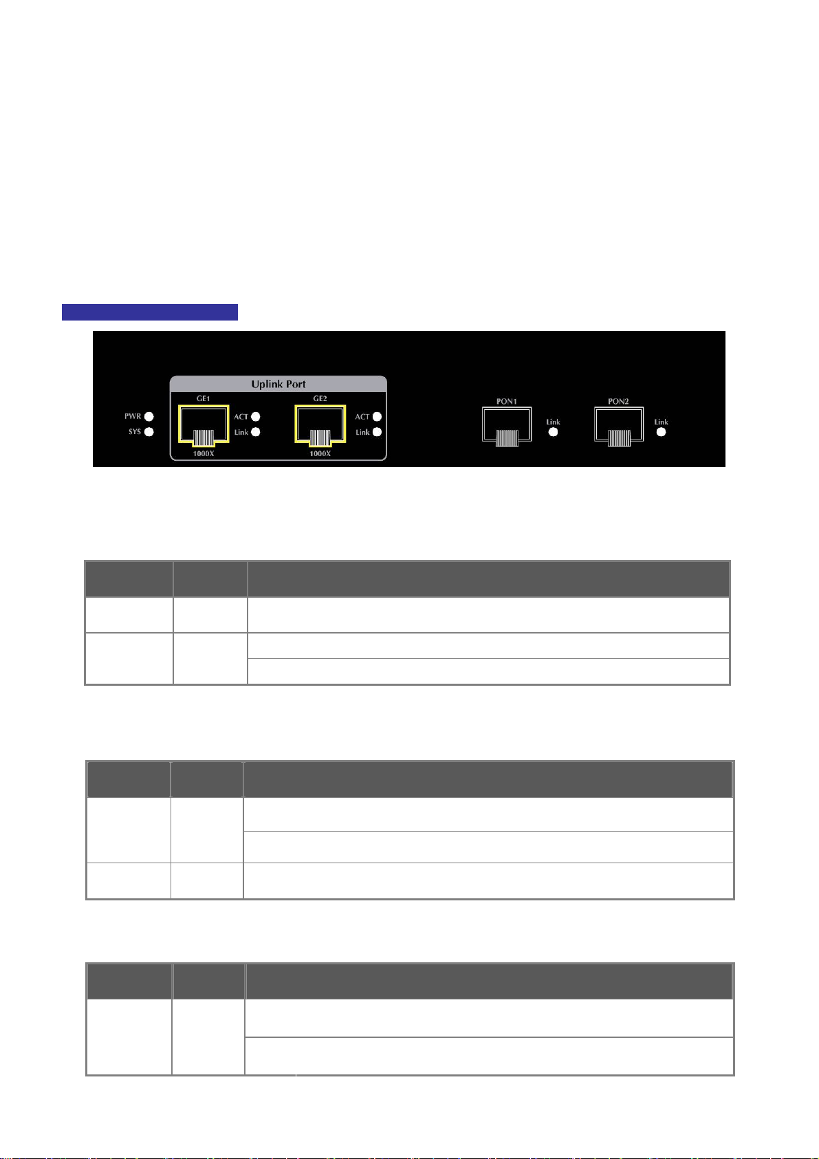
EPL-2000 LED Indication
Figure 2-2 EPL-2000 LED Panel
■ System
LED Color Function
PWR Green Lights: To indicate that the Switch is powered on.
SYS Green
■ 1000BASE-SX/LX SFP interfaces (GE1 and GE2 Port)
LED Color Function
LINK Green
Blink: The OLT is ready for management
Off: The OLT is abnormal in system operation
Lights:
Off:
To indicate the link through that SFP port is successfully established.
To indicate that the SFP port is link-down.
ACT Green Blink:
■ 1000BASE-PX20 SFP PON interfaces (PON1 and PON2 Port)
LED Color Function
Lights:
LINK Green
Off:
To indicate that the switch is actively sending or receiving data over that port.
To indicate the link through that PON port is successfully established.
To indicate that the PON port is link-down.
11
Page 12

User’s Manual of EPL-2000
2.1.3 OLT Rear Panel
The rear panel of the GEPON OLT indicates an AC inlet power socket, which accepts input power from 100 to 250V AC,
50-60Hz. Figure 2-3 shows the rear panel of this GEPON OLT.
EPL-2000 Rear Panel
Figure 2-3 Rear Panel of EPL-2000
■ AC Power Receptacle
For compatibility with electric service in most areas of the world, the GEPON OLT’s power supply automatically adjusts to
line power in the range of 100-250V AC and 50/60 Hz.
Plug the female end of the power cord firmly into the receptable on the rear panel of the GEPON OLT and the other end of
the power cord into an electric outlet and then the power will be ready.
There is a power switch for AC power input use only, whereas DC power input has no power switch.
The device is a power-required device; if your networks should be active all the time, please
consider using UPS (Uninterrupted Power Supply) for your device. It will prevent you from
network data loss or network downtime.
In some areas, installing a surge suppression device may also help to protect your GEPON
OLT from being damaged by unregulated surge or current to the switch or the power adapter.
2.2 Installing the OLT
This section describes how to install your GEPON OLT and make connections to the GEPON OLT. Please read the following
topics and perform the procedures in the order being presented. To install your GEPON OLT on a shelf, simply complete the
following steps.
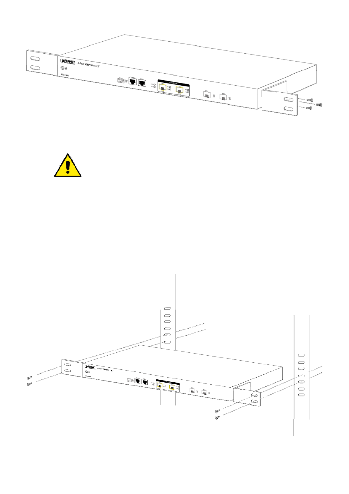
2.2.1 Rack Mounting
To install the GEPON OLT in a 19-inch standard rack, please follow the instructions described below:
Step 1: Place the GEPON OLT on a hard flat surface, with the front panel positioned towards the front side.
Step 2: Attach the rack-mount bracket to each side of the GEPON OLT with supplied screws attached to the package.
Figure 2-4 shows how to attach brackets to one side of the GEPON OLT.
12
Page 13
User’s Manual of EPL-2000
Figure 2-4 Attaching Brackets to the GEPON OLT.
You must use the screws supplied with the mounting brackets. Damage caused to the parts by
using incorrect screws would invalidate the warranty.
Step 3: Secure the brackets tightly.
Step 4: Follow the same steps to attach the second bracket to the opposite side.
Step 5: After the brackets are attached to the GEPON OLT, use suitable screws to securely attach the brackets to the rack, as
shown in Figure 2-5.
Figure 2-5 Mounting the GEPON OLT on a Rack
13
Page 14
User’s Manual of EPL-2000
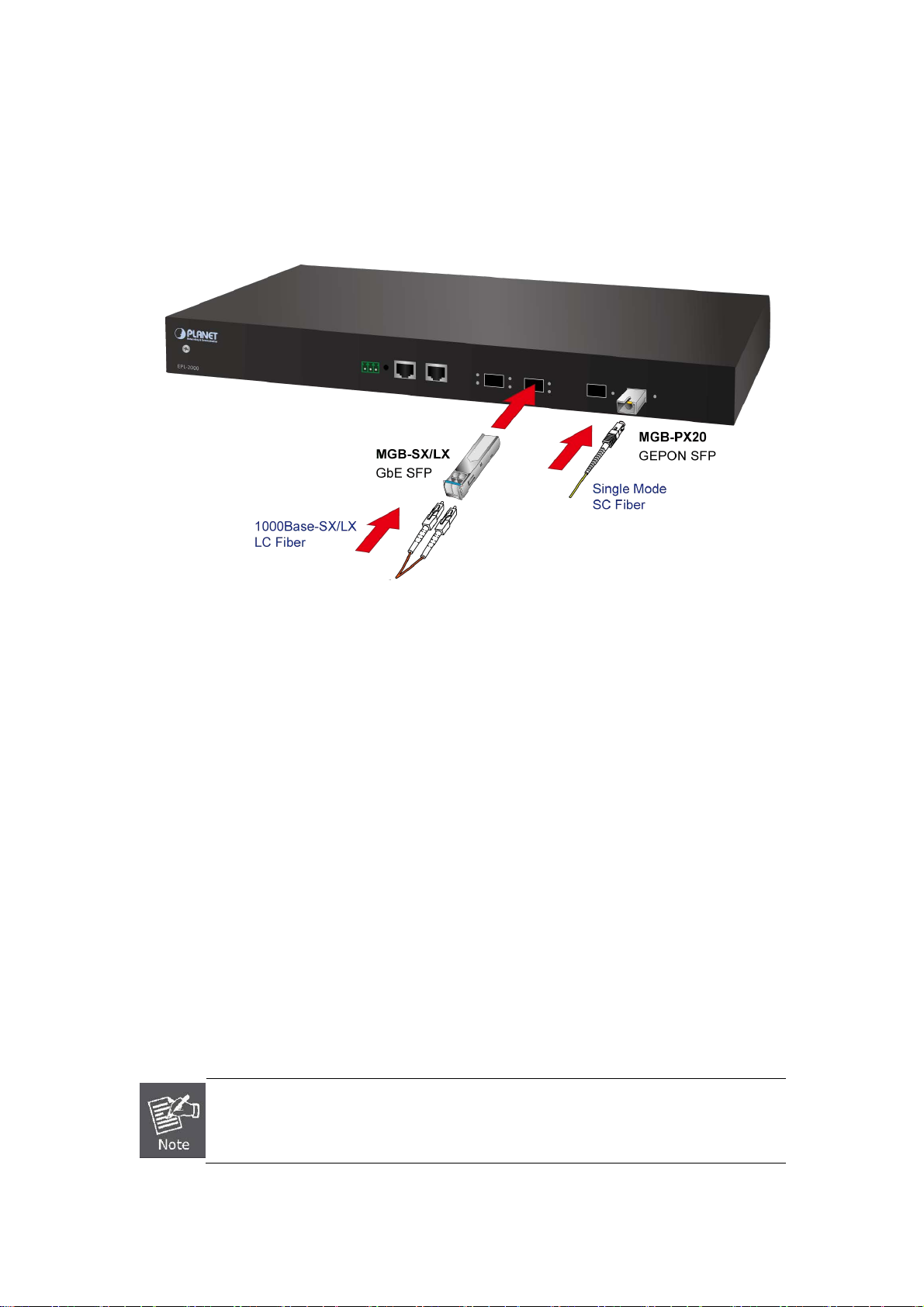
2.2.2 Installing the SFP Transceiver
The sections describe how to insert an SFP transceiver into an SFP slot. The SFP transceivers are hot-pluggable and
hot-swappable. You can plug in and out the transceiver to/from any SFP port without having to power down the GEPON OLT as
Figure 2-6 shows.
Figure 2-6 Plugging in the SFP Transceiver
Approved PLANET SFP Transceivers
PLANET GEPON OLT supports both Single mode and Multi-mode SFP transceivers. The following list of approved PLANET
SFP transceivers is correct at the time of publication:
1000BASE-X SFP modules:
■ MGB-SX SFP (1000BASE-SX SFP transceiver / Multi-mode / 850nm / 220m~550m)
■ MGB-LX SFP (1000BASE-LX SFP transceiver / Single mode / 1310nm / 10km)
■ MGB-L30 SFP (1000BASE-LX SFP transceiver / Single mode / 1310nm / 30km)
■ MGB-L50 SFP (1000BASE-LX SFP transceiver / Single mode / 1310nm / 50km)
■ MGB-LA10 SFP (1000BASE-LX SFP transceiver / WDM Single mode / TX: 1310nm, RX: 1550nm/ 10km)
■ MGB-LB10 SFP (1000BASE-LX SFP transceiver / WDM Single mode / TX: 1550nm, RX: 1310nm / 10km)
■ MGB-TSX SFP (1000BASE-SX SFP transceiver / Multi-mode / 850nm / 220m ~550m; -40~75
■ MGB-TLX SFP (1000BASE-SX SFP transceiver / Signle mode / 1310nm / 10km; -40~75℃)
■ MGB-TL30 SFP (1000BASE-SX SFP transceiver / Signle mode / 1310nm / 30km; -40~75℃)
℃)
■ MGB-TL70 SFP (1000BASE-SX SFP transceiver / Signle mode / 1310nm / 70km; -40~75℃)
GEPON OLT EPL-2000 SFP ports of GE1 and GE2 are configured in 1000Mbps Forced
Mode. If want to make the connection successfully, the switch’s SFP ports should also be in
1000Mbps Forced Mode. Otherwise, the connection might fail.
Before connecting the other GEPON OLT, workstation or Media Converter,
14
Page 15
User’s Manual of EPL-2000
1. Make sure both sides of the SFP transceiver are with the same media type, for example: 1000BASE-SX to 1000BASE-SX,
1000Bas-LX to 1000BASE-LX.
2. Check whether the fiber-optic cable type matches the SFP transceiver model.
To connect to 1000BASE-SX SFP transceiver, use the multi-mode fiber cable, with one side being male duplex LC
connector type.
To connect to 1000BASE-LX SFP transceiver, use the single-mode fiber cable, with one side being male duplex LC
connector type.
Conn ecting the fiber cable
1. Insert the duplex LC connector on the network cable into the SFP transceiver.
2. Connect the other end of the cable to a device – switches with SFP installed, fiber NIC on a workstation or a Media
Converter.
3. Check the LNK/ACT LED of the SFP slot on the front of the GEPON OLT. Ensure that the SFP transceiver is operating
correctly.
4. Check the Link mode of the SFP port if the link fails. Works well with some fiber-NICs or Media Converters. Set the Link
mode to “1000 Force” if needed.
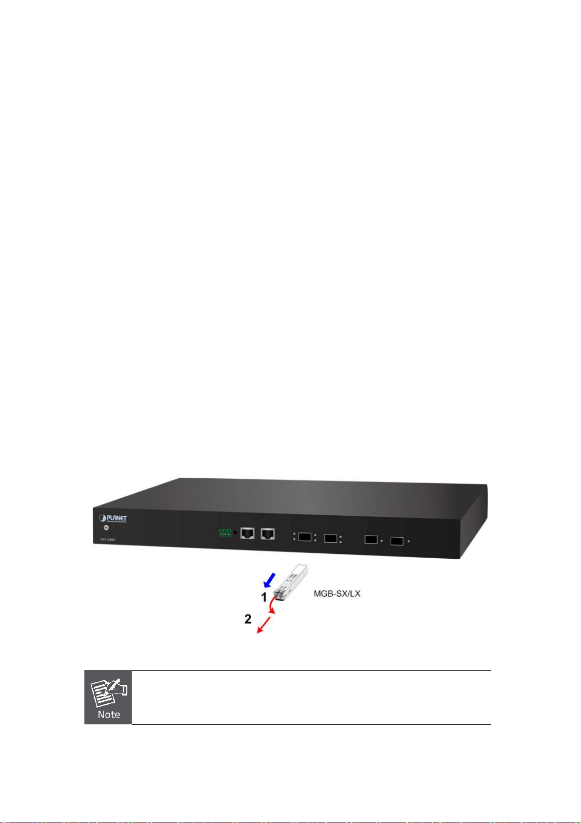
Removing the transceiver module
1. Make sure there is no network activity by consulting or checking with the network administrator. Or through the
management interface of the switch/converter (if available), disable the port in advance.
2. Remove the Fiber Optic Cable gently.
3. Turn the handle of the MGB module to a horizontal position.
4. Pull out the module gently through the handle.
Figure 2-8 Pulling Out the SFP Transceiver
Never pull out the module without pulling the handle or the push bolts on the module.
Directly pulling out the module with force could damage the module and SFP module slot of
the GEPON OLT.
15
Page 16

User’s Manual of EPL-2000
3. MANAGEMENT SOFTWARE INSTALLATION
This chapter explains the methods that you can use to configure management access to the GEPON OLT. It describes the types
of management applications and the communication and management protocols that deliver data between your management
device (workstation or personal computer) and the system. It also contains information about port connection options.
This chapter covers the following topics:
Requirements
Management Access Overview
MySQL Installation
EMS Utility Installation
SNMP Access
3.1 Requirements
The GEPON OLT provides a GUI utility to manage the system; the following equipment is necessary for further management.
Subscriber PC is installed with Ethernet NIC (Network Card)
MySQL Software (Windows Platform) http://dev.mysql.com/
EMS Software (Windows Platform)
Management Port connection
Network cables -- use standard network (UTP) cables with RJ45 connectors
PON Port connection
Fiber Transceiver - Slot with a 1000BASE-PX20 SFP PON transceiver
Fiber Cable - Using single mode of Fiber (SC) cable
16
Page 17
User’s Manual of EPL-2000
3.2 Management Access Overview
The GEPON OLT EPL-2000 supports 10/100Mbps Management interface and two 1000BASE-X net interfaces for
TCP/IP-based GUI Management. The GEPON OLT gives you the flexibility to access and manage it by using any or all of the
following methods:
EMS (Element Management System) Utility
An external SNMP-based network management application
Each of these management methods has their own advantages. Table 3-1 compares the two management methods.
Method Advantages Disadvantages
EMS Utility
SNMP Agent
Ideal for configuring the EPL-2000
Compatible with most popular
Windows-based Systems
Most visually appealing
Communicates with switch functions at
the MIB level
Based on open standards
Table 3-1 Management Methods Comparison
Can’t remote control over Etherent
Requires SNMP manager software
Least visually appealing of all three methods
Some settings require calculations
Security can be compromised (hackers need
only know the community name)
3.3 EMS Utility Management
The EMS (Element Management System) Utility comes with sophisticated software Graphical User Interface (GUI). It is highly
intuitive and allows the user to control the GEPON and set such things as SLAs, bridging and VLAN modes, static table entries,
and to perform firmware upgrades, etc. It is found in the Utility folder on the CD provided. There are two softwares that need to
be installed in your management PC:
Microsoft MySQL Server
EMS Utility
To install and use the GUI, do the following two sections.
17
Page 18
User’s Manual of EPL-2000
3.3.1 MySQL Server Installation
1. Please visit MySQL official website http://dev.mysql.com/ and download MySQL-Essential-5.1.73-win32.msi or
MySQL-Essential-5.1.73-win64.msi for the Windows system.
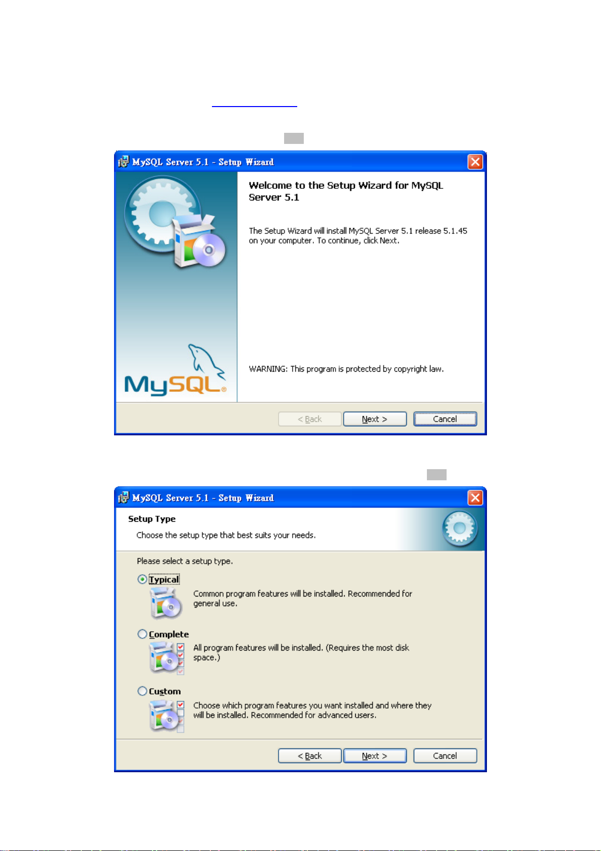
2. Once the Setup program starts running, please click “Next” button for starting installation.
Figure 3-2 MySQL Installation Screen
3. When the Setup Type window appears, choose the default “Typical” mode. Please click “Next” button.
Figure 3-3 Setup Type Screen
18
Page 19
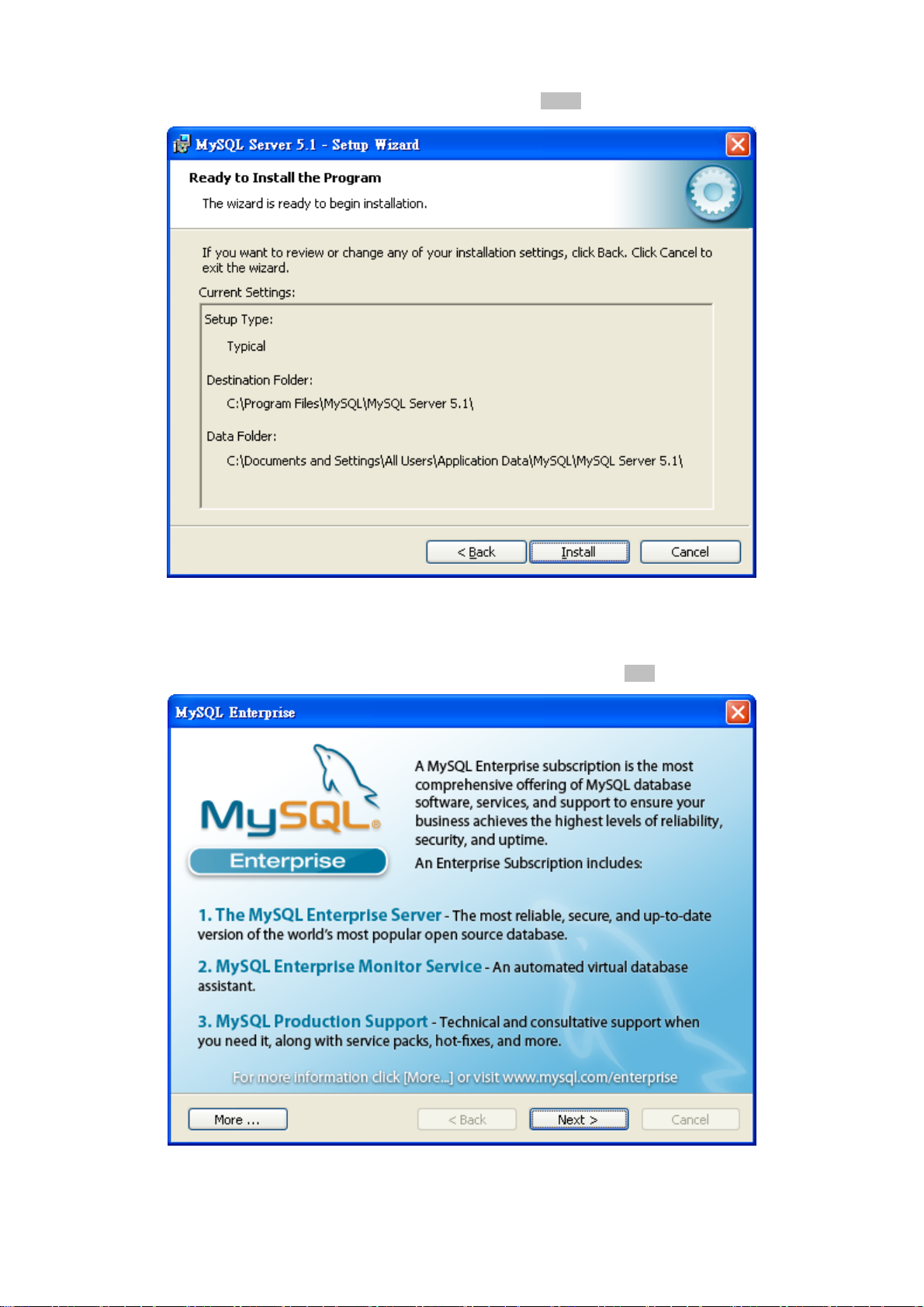
4. When the Ready to Install the Program window appears, please click “Install” button.
User’s Manual of EPL-2000
Figure 3-4 Begin Installation Wizard Screen
5. When the installation is done, the MySQL Enterprise window appears. Please click “Next” button.
Figure 3-5 MySQL Enterprise Screen
19
Page 20
User’s Manual of EPL-2000
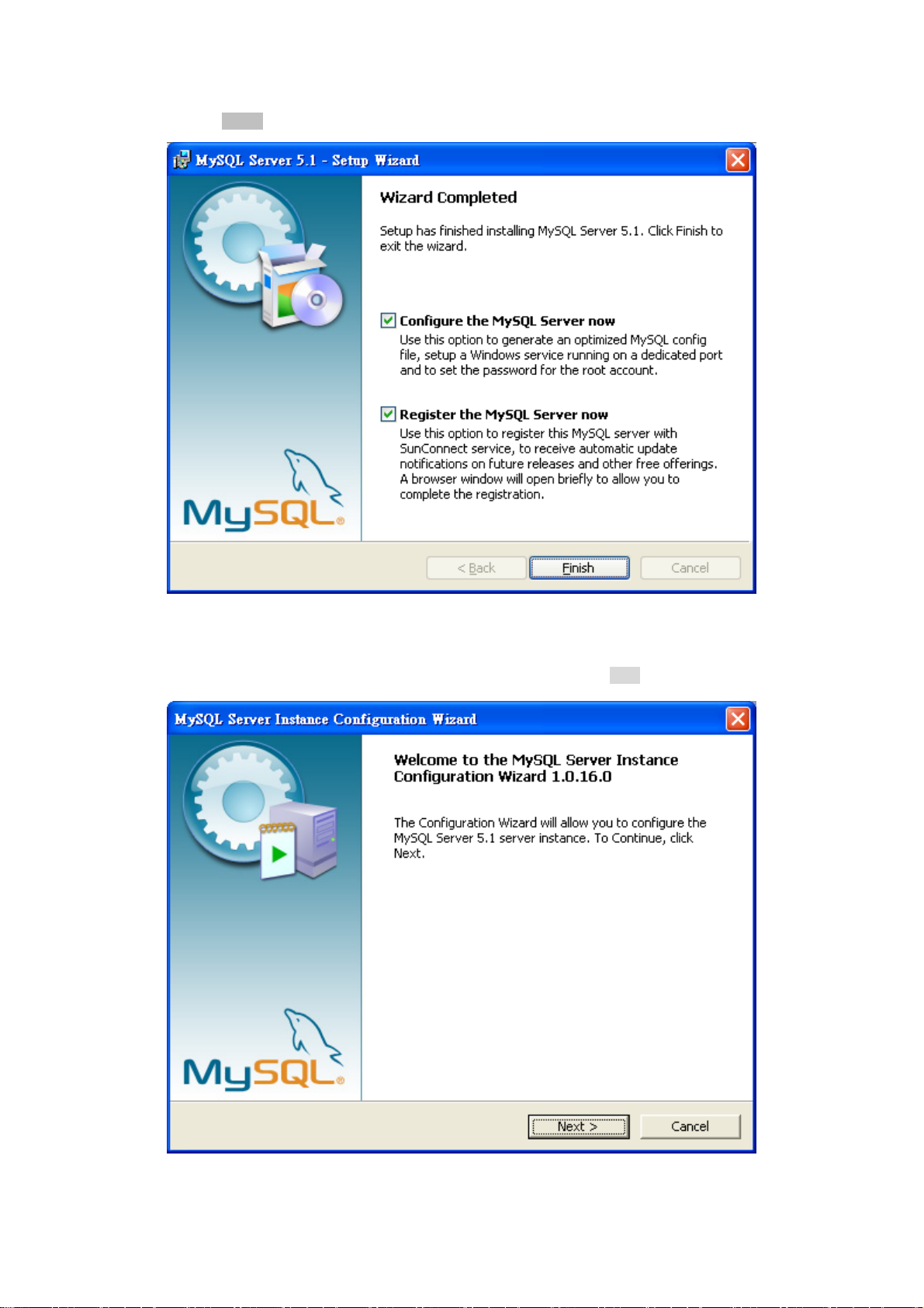
6. The “Wizard Completed” window appears, and it will ask for Configure the MySQL server and Register the MySQL Server
now. Please click “Finish” button.
Figure 3-6 Wizard Completed Screen
7. The MySQL Server Instance Configuration Wizard window appears; please click “Next” button.
Figure 3-7 MySQL Configuration Wizard Screen
20
Page 21
User’s Manual of EPL-2000
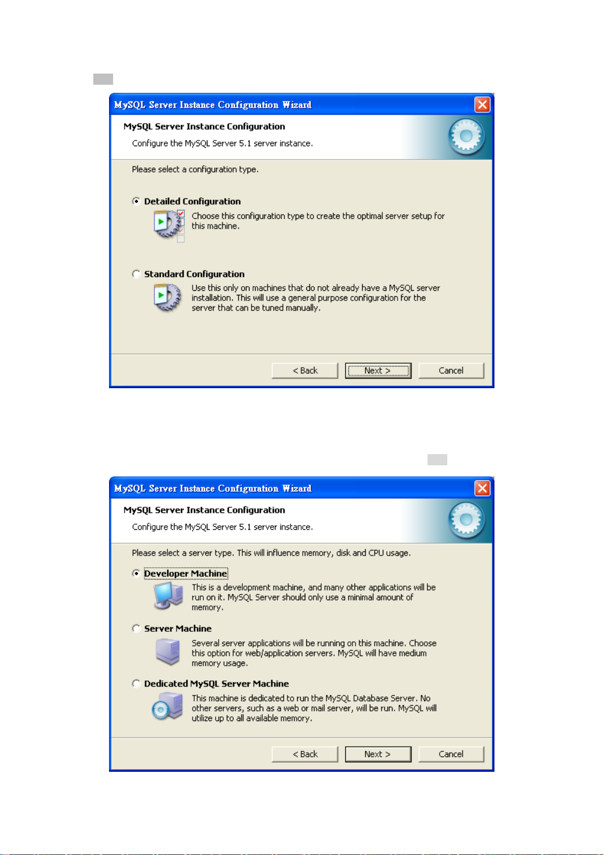
8. The MySQL Server Instance Configuration window appears; keep the default setting of “Detailed Configuration” and
click “Next” button.
Figure 3-8 MySQL Server Instance Configuration (1) Screen
9. Please select a Server type. Keep the default setting of “Developer Machine” and click “Next” button.
Figure 3-9 MySQL Server Instance Configuration (2) Screen
21
Page 22
User’s Manual of EPL-2000
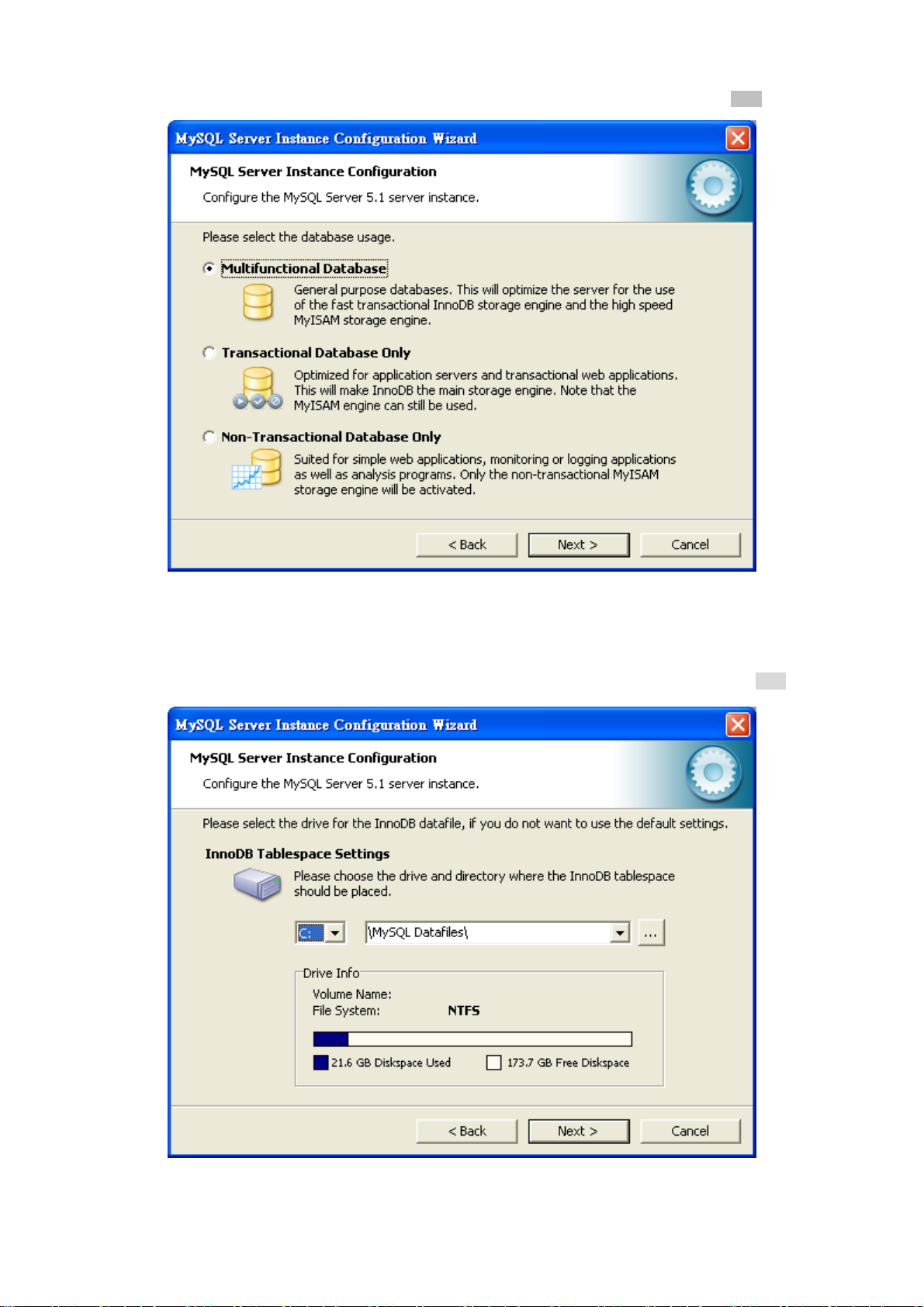
10. Please select the database usage. Keep the default setting of “Multifunctional Database” and click “Next” button.
Figure 3-10 MySQL Server Instance Configuration (3) Screen
11. Choose where you want to place the InnoDB Datafile. Here is the remaining default setting. Please click “Next” button.
Figure 3-11 MySQL Server Instance Configuration (4) Screen
22
Page 23
User’s Manual of EPL-2000
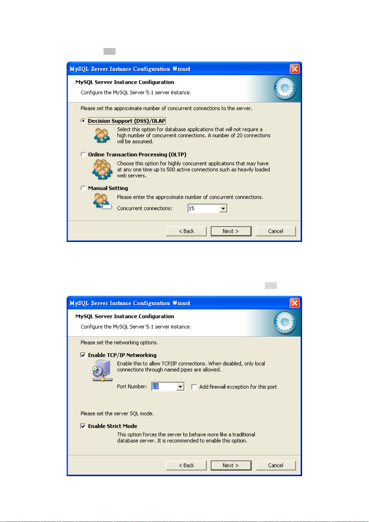
12. Please set the approximate number of concurrent connections. Keep the default setting of “Decision Support
(DSS)/OLAP“ and click “Next” button.
Figure 3-12 MySQL Server Instance Configuration (5) Screen
13. Please set the Network options and Server SQL mode. Keep the default setting and click “Next” button.
Figure 3-13 MySQL Server Instance Configuration (6) Screen
23
Page 24
User’s Manual of EPL-2000
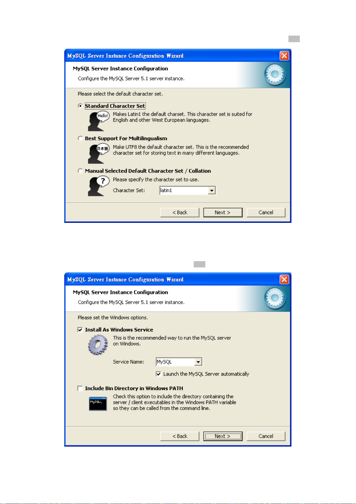
14. Please select the default character set. Keep the default setting of “Standard Character Set” and click “Next” button.
Figure 3-14 MySQL Server Instance Configuration (7) Screen
15. Please set the Windows options. Keep default setting and click “Next” button.
Figure 3-15 MySQL Server Instance Configuration (8) Screen
24
Page 25
User’s Manual of EPL-2000
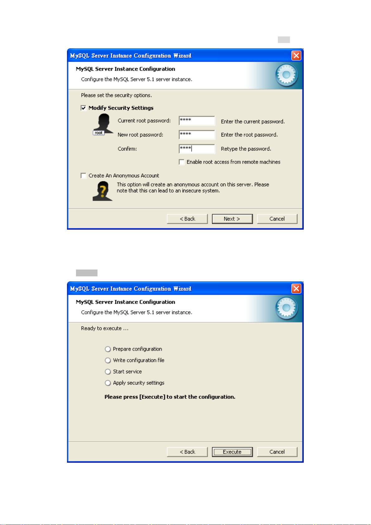
16. Please set the security options. Type the password “1234” for current root and new root. Click “Next” button.
Figure 3-16 MySQL Server Instance Configuration (9) Screen
17. Please click “Execute” button for starting the configuration.
Figure 3-17 MySQL Server Instance Configuration (10) Screen
25
Page 26

User’s Manual of EPL-2000
18. Please give a check to “Configuration file created”, “Windows service MySQL installed”, “Service started successfully” and
“Security applied”, and then click “Finish” button.
Figure 3-18 MySQL Server Finish Screen
26
Page 27

User’s Manual of EPL-2000
3.3.2 EMS Utility Installation
1. Insert the bundled CD disk into the CD-ROM drive to launch the autorun program. Once completed, a welcome menu
screen will appear. Click the “PL-EMS” hyperlink, the InstallShield Wizard dialog box will appear below.
2. Once the Setup program starts running, please click “Next” button for starting installation.
Figure 3-19 PL-EMS Setup Wizard Screen
3. During the installation, it will ask for the place to put the PL_EMS folder.
Figure 3-20 PL-EMS Folder Installation Screen
27
Page 28

4. Click “Install” for starting installation.
User’s Manual of EPL-2000
Figure 3-21 PL-EMS Installation Screen
5. Click “Finish” button for completing the EMS Setup.
Figure 3-22 PL-EMS Installation Completing Screen
28
Page 29

User’s Manual of EPL-2000
6. When the PL-EMS is done, two icons -- PL Server and PL Client – will appear on the desktop.
3.3.3 Starting PLANET EMS Management
The following shows how to start-up the PL-EMS Management on the management PC.
1. Double-click the PL Server icon on the PC desktop. After a couple of seconds, it will appear on the lower-right corner of
the system tray.
gure 3-23 PL Server Icon
Fi
2. Double-click the PL Client icon on the PC desktop. It will pop-up a window to enter the user name and password. Please
enter the default user name "admin" and password “admin”. The login screen in Figure 3-24 appears.
Figure 3-24 PL Client Icon and Login Window
29
Page 30

User’s Manual of EPL-2000
3. After entering the user name and password, the PL-EMS main screen will appear as in Figure 3-25.
Figure 3-25 Main Screen of EPL-2000 GEPON OLT
3.4 SNMP-based Network Management
You can use an external SNMP-based application to configure and manage the GEPON OLT, such as SNMPc Network
Manager, HP Openview Network Node Management (NNM) or What’s Up Gold. This management method requires the SNMP
agent on the switch and the SNMP Network Management Station to use the same community string. This management
method, in fact, uses two community strings: the get community string and the set community string. If the SNMP Net-work
management Station only knows the set community string, it can read and write to the MIBs. However, if it only knows the get
community string, it can only read MIBs. The default gets and sets community strings for the GEPON OLT are public.
Figure 3-26 SNMP Management Diagram
30
Page 31

User’s Manual of EPL-2000
4. EMS Management System
PLANET GEPON solutions include the OLT EPL-2000 and ONUs -- EPN-102 and EPN-103. The following information
introduces the software configuration.
This document explains how to use the EMS Utility for the purpose of evaluating the functionality and usability of Host Interface
Protocol. This manual assumes that the reader has a technical background and a base level of understanding regarding the
basic operation of PON equipment. The EMS Utility is a demonstration package, intended for evaluation purposes only.
Organization of the EMS Utility
The screen real estate used by the EMS Utility is divided into three sash windows and one EMS toolbar.
The upper left panel displays the entities that may be managed by the Host Interface, including the OLT, ONUs and
Logical Links. This sash window will be referred to as the Element Status Window.
Left clicking on an entity with the mouse will open a tabbed panel in the upper right sash window that may be used to
manage the entity. This sash window will be referred to as the Entity Management Window.
The bottom sash window is used for the purpose of logging the host interface message that is sent and received by the
EMS Utility, and will be referred to as the Message Log.
If the OLT is running normally and the ONUs register each of their LLIDs, you should see something similar to the figure. The left
handed pane shows the MAC addresses of the OLT and the ONU’s LLIDs. Depending on the number of ONUs, LLIDs, MAC
addresses, etc., you may see something slightly different. If the GUI fails to connect to the OLT, check the IP addresses of the
Host PC and the management port. Make sure you can ping the IP address assigned to the management port or uplink port.
Also verify that the Host and management IP addresses match in the GUI’s Utilities.
31
Page 32

User’s Manual of EPL-2000
4.1 EMS Toolbar
The toolbar includes System, Alarm, Config, Performance and Help features which allows users to do advanced setting.
Figure 4-1 EPL-2000 GEPON OLT Toolbar
4.1.1 System:
It includes System Config, Mib Browser, Database Mainteance, User Manage and Exit.
Figure 4-2 Toolbar of System Screen
4.1.1.1 System Config
Figure 4-3 System Config Screen
32
Page 33

The popup window includes the following fields:
Object Description
User’s Manual of EPL-2000
Language:
IP:
Port:
Timeout(Sec):
Retry:
Allows user to select the language: English and Simplified Chinese.
Enter the IP address which allows user to remote control from other PC with
same IP subnet address. The default IP is 127.0.0.1.
Enter the UDP port number. The default port is 8888.
Enter relay time. The default timeout is 10 Sec.
Reconnection times. The default retry is 2.
4.1.1.2 MIB Browser
A management information base (MIB) is a virtual database used for managing the entities in a communications network.
A built-in trap receiver can receive SNMP traps and handle trap storm.
Figure 4-4 MIB Browser Screen
33
Page 34
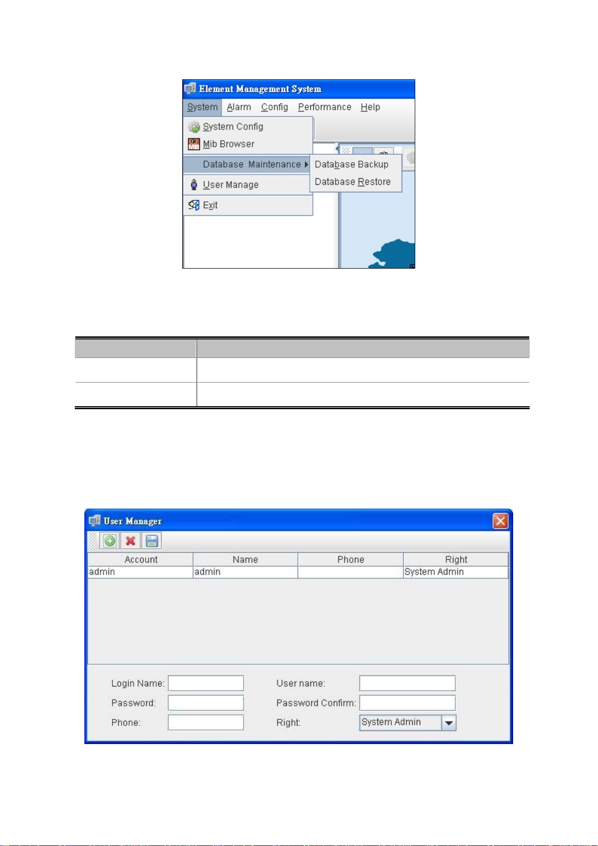
4.1.1.3 Database Maintenance
Figure 4-5 Database Maintenance screen
The popup window includes the following fields:
User’s Manual of EPL-2000
Object Description
Database Backup:
Database Restore:
Save the current data
Restore the previous backup data
4.1.1.4 User Manage
It is allowed to configure the GEPON OLT to authenticate users logging into the system for management access using local
authentication methods. The EPL-2000 provides totally three different security levels for local user management.
Figure 4-6 User Manager Screen
34
Page 35

The popup window includes the following fields:
Object Description
User’s Manual of EPL-2000
:
:
:
Login Name:
User name:
Password:
Password Confirm:
Phone:
Right:
Add New Account
Delete Account
Save Account
Enter the Name for login
Enter the Name for user
Enter the Password
Enter the Password for confirming again
Enter the Phone No.(Optional)
Allows user to choose right
- System Admin
- Net Manager
- Comm User
4.1.1.5 Exit
Exit the Element Management System
4.1.2 Alarm:
It includes Alarm Query, Config Trap Rule, System Log and Trap Window.
Figure 4-7 Toolbar of Alarm Screen
35
Page 36

User’s Manual of EPL-2000
4.1.2.1 Alarm Query
The OLT alarms manager works in concert with the ONUs to provide enhanced management capabilities and complementary
set of OLT specific alarms.
The popup window includes the following fields:
Object Description
Time:
Alarm Status:
Severity:
Network Element:
Page Record Counts:
Select Trap Name:
Select the Range of time for filtering.
Allows user to choose Handler or No Handler.
Allows user to choose the Level of Alarm.
Allows user to choose the Element of devices.
Allows user to edit the number of events for per page.
Allows user to choose the Traps
Figure 4-8 Alarm Query screen
36
Page 37

4.1.2.2 Config Trap Rule
User’s Manual of EPL-2000
Figure 4-9 Config Trap Rule screen
The popup window includes the following fields:
Object Description
Refresh:
Apply:
Close:
Refresh the Configuration.
Apply the configuration.
Close the Alarm Filter.
37
Page 38

User’s Manual of EPL-2000
4.1.2.3 System Log
The GEPON EMS system log information is provided here. This window allows you to log the messages happened in this
system for later reference.
Figure 4-10 System Log screen
The popup window includes the following fields:
Object Description
From Time:
End Time:
User name:
Page Record:
Search:
Save:
Choose the time you want to start.
Choose the time you want to end.
Choose the user.
Allows user to edit the number of logs for each page.
Start searching the logs.
Save the Logs.
4.1.2.4 Trap Window
This function displays the EPL-2000 trap; it includes Severity, Handler, Trap Object and more.
Figure 4-11 Trap Window Screen
38
Page 39

4.1.3 Config
This feature allows user to configure the Top Tree, EPL-2000, PON Card and ONU property.
Figure 4-12 Toolbar of Config Screen
User’s Manual of EPL-2000
The popup window includes the following fields:
Object Description
Add:
Modify:
Delete:
Change Map:
Upload:
Device Upgrade:
Allows user to add Location and Device
Allows user to modify the property of Devices like: EPL-2000 and PON Card.
Allows user the delete the Devices.
Allows user to change the background Map.
Allows user to upload new Map.
Allows user to upgrade firmware for EPL-2000 or ONU
For more details, please refer to Chapter 4.5 “How to upgrade EPL-2000”
39
Page 40

User’s Manual of EPL-2000
4.1.4 Performance
This performance function helps user to verify the OLT connection. This window allows user to issue ICMP PING packets to
troubleshoot IP connectivity issues.
Once you select the target OLT in the Top Tree and click Performance\Ping from the Toolbar, ICMP packets are transmitted. The
report windows pop up automatically until responses to all packets are received, or until a timeout occurs. The Ping screen in
Figure 4-13 appears.
Figure 4-13 Toolbar of Perofrmance screen
Be sure the target OLT’s IP Address is within the same network subnet of the EMS workstation, or
you have to set up the correct gateway IP address.
4.1.5 Help
Allows user to change the color of window and language.
Figure 4-14 Skin Screen
40
Page 41

User’s Manual of EPL-2000
Figure 4-15 Language Screen
The popup window includes the following fields:
Object Description
Skin:
Lauange:
About:
Allows user to change the color of window
Allows user to choose two kinds of languages: English and Simplified Chinese.
Shows the version of EMS utility
Figure 4-16 About Screen
41
Page 42

User’s Manual of EPL-2000
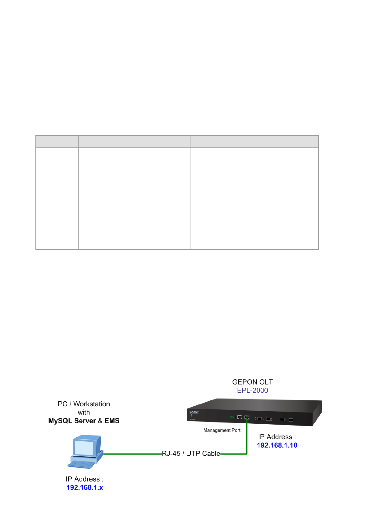
4.2 OLT Management
To manage EPL-2000, EMS manager needs to add EPL-2000 device. They can add and manage the EPL-2000 from the two
types of interfaces:
Management Port – the 10/100BASE-TX RJ45 interface
Uplink ports – the two 1000BASE-X SFP interfaces
The EPL-2000 is shipped with default IP addresses as follows:
Management Port: IP Address: 192.168.1.10
Subnet Mask: 255.255.255.0
Uplink Ports: IP Address: 192.168.10.100
Subnet Mask: 255.255.255.0
Right-click Top Tree and then click [Add Device] in the interface as the windows appear below.
Figure 4-17 Top Tree Interface Screen
Figure 4-18 Add Device Screen
42
Page 43

User’s Manual of EPL-2000
For example, add EPL-2000 through Management Port connection
Please enter the EPL-2000 default IP address “192.168.1.10”, Read Community “public” and Write Community “private” of
the management port.
Double-click the EPL-2000 device node unit in the topology tree, and click Chassis Management in the interface as the window
appears below:
Figure 4-19 EPL-2000 Interface Screen
43
Page 44

User’s Manual of EPL-2000
Figure 4-20 EPL-2000 OLT Management Screen
4.2.1 System Basic Information
The Basic System Information page provides information for the current device information. Basic System Information page
helps an OLT administrator to identify the System Model, System Description, System Location and System Contact.
Figure 4-21 System Basic Information Screen
The window includes the following fields:
Object Description
System Model:
System Location:
System Description:
System Contact:
Model name of OLT
Allows user to fill in the words for system location
Allows user to fill in the words for system description
Allows user to fill in the words for system contact
44
Page 45

User’s Manual of EPL-2000
4.2.2 Basic Information
The Basic System Info page provides information for the current device information. Basic System Info page helps an OLT
administrator to identify the firmware / hardware version, System Config and Switch Mode Configure.
The window includes the following fields:
Object Description
Card Type:
Serial NO.:
Hardware Version:
Firmware Version:
Running Status:
Running Time:
Console Port Speed:
oam Type:
The OLT device type, EPL-2000 is epon-olt type.
The manufacture number.
The version of Current Hardware.
The version of Current Firmware.
Status of EPL-2000.
The period of time the device has been operational.
The baud rate of Console Port. (Only for Manufacturer)
The default type is ctc-broadcom.
Figure 4-22 Basic Information Screen
Read Community:
R/W Community:
Trap Receiver
1~4 IP Address:
Outbandip:
OutbandMask:
Indicates the community read access string to permit access to SNMP agent.
Indicates the community write access string to permit access to SNMP agent.
Assign IP address of host to receive trap from the device.
Manage Port IP address, the default is 192.168.1.10.
Manage Port subnet mask, the default is 255.255.255.0
45
Page 46

User’s Manual of EPL-2000
4.2.3 Net Interface Management
The system supports two Management IP ports: One is in-band IP and one is out-band IP ports. This page is allow you to
modify the in-band IP
The window includes the following fields:
Object Description
Inband IP Address:
Inband IP Netmask:
Inband Gateway:
VLAN[1~4094]:
Inband Manage enable:
Allows user to change the IP Address.
The default IP address of Net interface is 192.168.10.100
Allows user to change the Network Mask.
The default Network Mask of Net interface is 255.255.255.0
Allows user to change the Default Gateway.
The default IP address of Net interface is 192.168.10.1
Allows user to change the VLAN ID.
Default VLAN ID: 1
Allows user to manage EPL-2000 through GE1 and GE2 port.
Figure 4-23 Net Interface Management Screen
46
Page 47

User’s Manual of EPL-2000
4.2.4 User Manage
This Page provides an overview of the current users. Currently the only way to login as another user on the web server is to
close and reopen the browser. Please press “Add” button for adding new login user account, after setup is completed, press
“OK” button to take effect. Please login web interface with new user name and password, the screen in Figure 4-24 appears.
The window includes the following fields:
Object Description
Index:
User Name:
User Password:
Premission:
Login Timeout:
The number identifying the user.
The name identifying the user.
The password of the user. The allowed string length is 1 to 32.
The level of the user. There are three levels: guest, user and admin.
The login time for the user, when idle and over the setting time, it will login out
automatically.
Buttons
: Click to add a new user.
Figure 4-24 User Manage Screen
Add / Edit User
This Page configures a user
47
Page 48

The window includes the following fields:
Object Description
User’s Manual of EPL-2000
Figure 4-25 User Manage Screen
User Name:
User Password:
Premission:
Login Timeout:
The name identifying the user.
The password of the user. The allowed string length is 1 to 32.
The level of the user. There are three levels: guest, user and admin.
The login time for the user, when idle and over the setting time, it will login out
automatically.
4.2.5 IGMPSetting
This page allows user to modify the IGMP configuration.
Figure 4-26 IGMPsetting Screen
48
Page 49

The window includes the following fields:
Object Description
User’s Manual of EPL-2000
IgmpMode:
Robustness:
Queryinterval:
Queryresponselnterval:
Lastmemberqueryinterval:
Lastmemberquerycount:
Allows user to select IGMP mode.
Allows user to modify the Robusness, the range is 1 to 10.
Allows user to modify the Query interval, the range is 100 to 200.
Allows user to modify the Query respon interval, the range is 10 to 20.
Allows user to modify the last member query interval, the range is 10 to 20.
Allows user to modify the last member query count, the range is 1 to 5.
4.2.6 Trunk Management
Trunk Management optimizes port usage by linking 2 GE ports together to form a single Link Aggregated Groups (LAGs).
Trunk multiplies the bandwidth between the devices, increases port flexibility, and provides link redundancy.
As GEPON OLT EPL-2000 SFP Ports of GE1 and GE2 is configured in 1000Mbps Forced Mode, the
switch’s SFP Ports should also change to the same mode if the connection is to be established
successfully. Otherwise, the connection might fail.
49
Page 50

The window includes the following fields:
User’s Manual of EPL-2000
Figure 4-27 Trunk Management Screen
Object Description
Up Trunk:
Enable: Trunk function Enable.
Disable: Trunk function Disable.
4.2.7 VLAN Management
4.2.7.1 VLAN Overview
A Virtual Local Area Network (VLAN) is a network topology configured according to a logical scheme rather than the physical
layout. VLAN can be used to combine any collection of LAN segments into an autonomous user group that appears as a single
LAN. VLAN also logically segments the network into different broadcast domains so that packets are forwarded only between
ports within the VLAN. Typically, a VLAN corresponds to a particular subnet, although not necessarily. VLAN can enhance
performance by conserving bandwidth, and improve security by limiting traffic to specific domains.
■ IEEE 802.1Q Standard
IEEE 802.1Q (tagged) VLAN are implemented on the Switch. 802.1Q VLAN requires tagging, which enables them to span the
entire network (assuming all switches on the network are IEEE 802.1Q-compliant).
VLAN allows a network to be segmented in order to reduce the size of broadcast domains. All packets entering a VLAN will only
be forwarded to the stations (over IEEE 802.1Q enabled switches) that are members of that VLAN, and this includes broadcast,
multicast and unicast packets from unknown sources.
VLAN can also provide a level of security to your network. IEEE 802.1Q VLAN will only deliver packets between stations that are
members of the VLAN. Any port can be configured as either tagging or untagging.:
The untagging feature of IEEE 802.1Q VLAN allows VLAN to work with legacy switches that don't recognize VLAN tags
50
Page 51

User’s Manual of EPL-2000
in packet headers.
The tagging feature allows VLAN to span multiple 802.1Q-compliant switches through a single physical connection and
allows Spanning Tree to be enabled on all ports and work normally.
Some relevant terms:
- Tagging - The act of putting 802.1Q VLAN information into the header of a packet.
- Untagging - The act of stripping 802.1Q VLAN information out of the packet header.
■ 802.1Q VLAN Tags
The figure below shows the 802.1Q VLAN tag. There are four additional octets inserted after the source MAC address. Their
presence is indicated by a value of 0x8100 in the Ether Type field. When a packet's Ether Type field is equal to 0x8100, the
packet carries the IEEE 802.1Q/802.1p tag. The tag is contained in the following two octets and consists of 3 bits of user priority,
1 bit of Canonical Format Identifier (CFI - used for encapsulating Token Ring packets so they can be carried across Ethernet
backbones), and 12 bits of VLAN ID (VID). The 3 bits of user priority are used by 802.1p. The VID is the VLAN identifier and is
used by the 802.1Q standard. Because the VID is 12 bits long, 4094 unique VLAN can be identified.
The tag is inserted into the packet header making the entire packet longer by 4 octets. All of the information originally contained
in the packet is retained.
802.1Q Tag
User Priority CFI VLAN ID (VID)
3 bits 1 bits 12 bits
TPID (Tag Protocol Identifier) TCI (Tag Control Information)
2 bytes 2 bytes
Preamble
Destination
Address
Source
Address
VLAN TAG
Ethernet
Data FCS
Type
6 bytes 6 bytes 4 bytes 2 bytes 46-1500 bytes 4 bytes
The Ether Type and VLAN ID are inserted after the MAC source address, but before the original Ether Type/Length or Logical
Link Control. Because the packet is now a bit longer than it was originally, the Cyclic Redundancy Check (CRC) must be
recalculated.
Adding an IEEE802.1Q Tag
Dest. Addr. Src. Addr. Length/E. type Data Old CRC
Dest. Addr. Src. Addr. E. type Tag Length/E. type Data New CRC
Original Ethernet
New T agg ed Packet
Priority CFI VLAN ID
51
Page 52

User’s Manual of EPL-2000
■ Port VLAN ID
Packets that are tagged (are carrying the 802.1Q VID information) can be transmitted from one 802.1Q compliant network
device to another with the VLAN information intact. This allows 802.1Q VLAN to span network devices (and indeed, the entire
network – if all network devices are 802.1Q compliant).
Every physical port on a switch has a PVID. 802.1Q ports are also assigned a PVID, for use within the switch. If no VLAN are
defined on the switch, all ports are then assigned to a default VLAN with a PVID equal to 1. Untagged packets are assigned the
PVID of the port on which they were received. Forwarding decisions are based upon this PVID, in so far as VLAN are concerned.
Tagged packets are forwarded according to the VID contained within the tag. Tagged packets are also assigned a PVID, but the
PVID is not used to make packet forwarding decisions, the VID is.
Tag-aware switches must keep a table to relate PVID within the switch to VID on the network. The switch will compare the VID of
a packet to be transmitted to the VID of the port that is to transmit the packet. If the two VID are different the switch will drop the
packet. Because of the existence of the PVID for untagged packets and the VID for tagged packets, tag-aware and tag-unaware
network devices can coexist on the same network.
A switch port can have only one PVID, but can have as many VID as the switch has memory in its VLAN table to store them.
Because some devices on a network may be tag-unaware, a decision must be made at each port on a tag-aware device before
packets are transmitted – should the packet to be transmitted have a tag or not? If the transmitting port is connected to a
tag-unaware device, the packet should be untagged. If the transmitting port is connected to a tag-aware device, the packet
should be tagged.
■ Default VLANs
The Switch initially configures one VLAN, VID = 1, called "default." The factory default setting assigns all ports on the Switch to
the "default". As new VLAN are configured in Port-based mode, their respective member ports are removed from the "default."
■ Assigning Ports to VLANs
Before enabling VLANs for the switch, you must first assign each port to the VLAN group(s) in which it will participate. By default
all ports are assigned to VLAN 1 as untagged ports. Add a port as a tagged port if you want it to carry traffic for one or more
VLANs, and any intermediate network devices or the host at the other end of the connection supports VLANs. Then assign ports
on the other VLAN-aware network devices along the path that will carry this traffic to the same VLAN(s), either manually or
dynamically using GVRP. However, if you want a port on this switch to participate in one or more VLANs, but none of the
intermediate network devices nor the host at the other end of the connection supports VLANs, then you should add this port to
the VLAN as an untagged port.
■ Tagged and Untagged
Every port on an 802.1Q compliant network device can be configured as tagged or untagged.
52
Page 53

User’s Manual of EPL-2000
Tagged:
Untagged:
Frame Leave
Leave port is tagged Frame remains tagged Tag is inserted
Ports with tagging enabled will put the VID number, priority and other VLAN information into the
header of all packets that flow into those ports. If a packet has previously been tagged, the port
will not alter the packet, thus keeping the VLAN information intact. The VLAN information in the
tag can then be used by other 802.1Q compliant devices on the network to make
packet-forwarding decisions.
Ports with untagging enabled will strip the 802.1Q tag from all packets that flow into those
ports. If the packet doesn't have an 802.1Q VLAN tag, the port will not alter the packet. Thus,
all packets received by and forwarded by an untagging port will have no 802.1Q VLAN
information. (Remember that the PVID is only used internally within the Switch). Untagging is
used to send packets from an 802.1Q-compliant network device to a non-compliant network
device.
Frame Income
Income Frame is tagged Income Frame is untagged
Leave port is untagged Tag is removed Frame remain untagged
Table 4-2-1 Ingress/Egress port with VLAN VID Tag/Untag table
4.2.7.2 VLAN Configuration
To completely configure the VLAN functions on the GEOPN OLT, two of the following sub-menus are needed to be well
configured.
OLT Management \ VLAN Management
OLT Management \ Port \ Port Property
OLT Management \ VLAN Management
This page is used for configuring the OLT port VLAN. The VLAN Management page contains fields for managing ports that are
part of a VLAN.
53
Page 54

User’s Manual of EPL-2000
Figure 4-28 VLAN Management Screen
The window includes the following fields:
Object Description
VLAN ID:
Description:
Egress Ports:
Untagged Port:
Add:
Delete:
Set:
Indicates the ID of this particular VLAN.
Allows user to fill in the words for VLAN description
Selects specific port for VLAN group.
Select specific port for this check box to transmit outgoing frames without
VLAN-Tagged.
Add new VLAN ID configuration.
Delete VLAN ID.
Set VLAN configuration.
OLT Management \ Port \ Port Property
54
Page 55

User’s Manual of EPL-2000
Figure 4-29 Port Property Screen
The window includes the following fields:
Object Description
Port ID:
Port VID:
swPortvlanmode:
Ingress Filter:
This is the logical port name for this row.
Allows to assign PVID for selected port. The range for the PVID is 1-4094.
The PVID will be inserted into all untagged frames entering the ingress port. The
PVID must be the same as the VLAN ID whose port belongs to VLAN group, or
the untagged traffic will be dropped.
Allows user to modify the VLAN mode, there are two modes:
Vlan-access: Only allow Untagged frames
Vlan-Trunk: Allows Tagged and Untagged frames.
Enable ingress filtering for a port by checking the box. This parameter affects
VLAN ingress processing. If ingress filtering is enabled and the ingress port is not
a member of the classified VLAN of the frame, the frame is discarded.
Enabled
Disabled
By default, ingress filtering is disabled (no checkmark).
Determines whether the port accepts all frames or only VLAN tagged frames.
This parameter affects VLAN ingress processing. If the port only accepts tagged
frames, untagged frames received on the port are discarded.
Permit Frame Type:
Options:
allType
tagged
By default, the field is set to allType.
55
Page 56

4.2.8 IPTV Profile
This page allows user to create IPTV profile.
User’s Manual of EPL-2000
The window includes the following fields:
Object Description
Index:
Name:
Refresh:
Add:
Delete:
The number identifying the user.
Indicates the per IPTV profile name.
Refresh the Page. Any changes made locally will be undone.
Add new VLAN ID configuration.
Delete VLAN ID.
4.2.9 IPTV Channel
Figure 4-30 IPTV Profile Screen
This page allows for selecting the specific IPTV profile and creates their own IPTV channels.
56
Page 57

The window includes the following fields:
User’s Manual of EPL-2000
Figure 4-31 IPTV Channel Screen
Object Description
IPTV Profile:
Index:
Channel Name:
Multicast Group:
IPTV Vlan:
IPTV User ID:
User View Time:
The user can select specific IPTV Profile; the IPTV profile is creating by IPTV
profile page.
The number identifying the user.
Indicates the name of IPTV channel.
Allows user to fill the multicast streaming IP address.
Add IPTV VLAN ID configuration.
The User ID is meaning of ONU ethernet ports.
For example: EPN-103, there are two ethernet ports.
User ID1: Gigabit port (Port 1)
User ID2: Fast Ethernet Port (Port 2)
Configures the time for viewing IPTV channel.
4.2.10 Port Property
In Port Property you can configure the settings of each port to control the connection parameters, and the status of each port is
listed below:
57
Page 58

User’s Manual of EPL-2000
Figure 4-32 Port Property Screen
The popup window includes the following fields:
Object Description
Port ID:
Mode Config:
Flow Control Config:
Port VID:
swPortvlanmode:
This is the logical port name for this row.
That is only one speed 1000Mbps for SFP transceivers.
Whether or not the receiving node sends feedback to the sending node is
determined by this item. When enabled, once the device exceeds the input data
rate of another device, the receiving device will send a PAUSE frame which halts
the transmission of the sender for a specified period of time.
When disabled, the receiving device will drop the packet if too much to process.
Allows to assign PVID for selected port. The range for the PVID is 1-4094.
The PVID will be inserted into all untagged frames entering the ingress port. The
PVID must be the same as the VLAN ID whose port belongs to VLAN group, or
the untagged traffic will be dropped.
Allows user to modify the VLAN mode, there are two modes:
Vlan-access: Only allow Untagged frames
Vlan-Trunk: Allows Tagged and Untagged frames.
Port Enable:
Ingress Filter:
The port can be set to disable or enable mode.
If the port is set as ‘Disable’, it will not receive or transmit any packet.
Enable ingress filtering for a port by checking the box. This parameter affects
VLAN ingress processing. If ingress filtering is enabled and the ingress port is not
a member of the classified VLAN of the frame, the frame is discarded.
Enabled
Disabled
58
Page 59

User’s Manual of EPL-2000
By default, ingress filtering is disabled (no checkmark).
Determines whether the port accepts all frames or only VLAN tagged frames.
This parameter affects VLAN ingress processing. If the port only accepts tagged
frames, untagged frames received on the port are discarded.
Permit Frame Type:
Ingress Rate Control:
Ingress Rate Control Rate
[0~1000000]
Options:
allType
tagged
By default, the field is set to allType.
There are four kinds of Limit Rates:
1. LimitAll
2. LimitB
3. LimitM
4. LimitBMUC
Set up the Rate of Ingress Rate.
As GEPON OLT EPL-2000 SFP Ports of GE1 and GE2 are configured in 1000Mbps Forced
Mode, the switch’s SFP Ports should also be changed to 1000Mbps Forced Mode if the
connection is to be established successfully,. Otherwise, the connection might fail.
59
Page 60

User’s Manual of EPL-2000
4.2.11 Port Status
This page displays current port configurations and operating status – it is a ports’ configurations summary table. Via the
summary table, you can know status of each port clearly at a glance, like Port Link Up/Link Down status, Link Speed and Duplex
mode.
Figure 4-33 Port Status Screen
60
Page 61

User’s Manual of EPL-2000
4.3 PON Card Management
Double-click the PON Card device node unit in the topology tree or right-click PON Card Management in the interface as the
window shows below:
Figure 4-34 PON Card Interface Screen
4.3.1 Interface Information
This page displays the current PON Card Information – it is a PON Card Configuration page. Via the PON Card Configuration
page, you can know like PON Card MAC addresses or configure ONU AUTH and etc.
Figure 4-35 Interface Information Screen
61
Page 62

The popup window includes the following fields:
Object Description
PON MAC: Shows the PON1 interface MAC address.
ONU AUTH: Selects the Auth mode.
PON Port Enabled: Enabled or Disable the PON1 port.
Max LLID Number[0~239]: Allows for setting value of LLID
User’s Manual of EPL-2000
PON1 Interface Config:
PON2 Interface Config:
Registered LLID Number: Allows for setting number of Registered LLID.
On Line ONU Number: Shows how many current ONUs connects on PON1.
Upstream Bandwidth Left[kbps]: Shows how much cureent upstream
bandwidth left.
Downstream Bandwidth Left[kbps]: Shows how much cureent Downstream
bandwidth left.
PON MAC: Shows the PON2 interface MAC address.
ONU AUTH: Selects the Auth mode.
PON Port Enabled: Enabled or Disable the PON2 port.
Max LLID Number[0~239]: Allows for setting value of LLID
Registered LLID Number: Allows for setting number of Registered LLID.
On Line ONU Number: Shows how many current ONUs connects on PON1.
Upstream Bandwidth Left[kbps]: Shows how much cureent upstream
bandwidth left.
Downstream Bandwidth Left[kbps]: Shows how much cureent Downstream
bandwidth left.
62
Page 63

4.3.2 OLT Global Setting
User’s Manual of EPL-2000
Figure 4-36 OLT Global Setting Screen
The popup window includes the following fields:
Object Description
ONU P2P: Enabled/Disable the ONU P2P function.
Link Encryption:
Link Key Exchange Time:
Selects the link encryption mode, there are three modes.
None, Teknoves and CTC mode
Arranges the time of Link Key, the range is 1 to 65535.
63
Page 64

4.3.3 ONU Auth
User’s Manual of EPL-2000
The popup window includes the following fields:
Object Description
PON Port:
Index:
Mac Address:
LOID:
Password:
Allows for selecting which PON port for modifying.
The number identifying the user.
The MAC address of the entry.
The LOID of the entry, it is same as user name.
The password of the user. The allowed string length is 1 to 24.
If want to configure Onu Auth, the user must enable the ONU Auth from Interface infomraiton
page.
Figure 4-37 Onu Auth Screen
64
Page 65

User’s Manual of EPL-2000
4.4 ONU Management
Double-click the EPL-2000 device node unit in the topology tree or right-click Chassis Management in the interface as the
windows show below:
Figure 4-38 ONU Interface Screen
Figure 4-39 ONU Management Screen
65
Page 66

User’s Manual of EPL-2000
4.4.1 Basic Configuration
The Basic System page provides information on the current device status. Basic System page helps an OLT administrator to
identify the ONU device’s firmware / hardware version, ONU MAC Address, ONU Line Status and others.
The window includes the following fields:
Object Description
ONU ID:
ONU Device Type:
Description:
ONU Hardware Revision:
ONU Software Revision:
Max Allowed LLIDs:
Registered LLID Num:
ONU On Line Status:
Number of ONU Devices detected by EMS Utility.
Model name of ONU device.
Allows user to fill in the words for ONU description
Displays the ONU Hardware Version.
Displays the ONU Firmware Version.
Displays the ONU MAX
Displays the registered LLID Number of ONU.
Displays the current ONU status.
Figure 4-40 Basic Configuration Screen
ONU User Traffic Enable:
ONU Range Value:
Enable: Allows user to transfer data via port.
Disable: User is not allowed to transfer data via port.
Displays the distances from OLT to ONU.
(Short cabling would make detection difficult.
66
Page 67

User’s Manual of EPL-2000
Uni Number:
Mgt Oam:
CTC Version:
Service Type:
CATV Support:
Displays the ONU Uni unmber.
Displays the ONU OAM management type.
Displays the CTC version.
Displays the ONU service type.
Displays the ONU CATV support type.
4.4.2 Global Parameter
This page allows user to configure the IGMP Fastleave, IPTV Profile and etc.
The window includes the following fields:
Object Description
IGMP Fastleave:
IPTV Profile:
onuLaserRXPower(dbm):
onuLaserTXPower(dbm):
Enable: Open the ONU IGMP Fastleave function.
Disable: Close the ONU IGMP Fastleave function.
Fill the IPTV Profile name which has created from EPL-2000 IPTV Profile page.
Displays the ONU Fiber Laser RX power.
Displays the ONU Fiber Laser TX power.
Figure 4-41 Global Parameter Screen
67
Page 68

4.4.3 ONU Multicast Group
This page displays all of your multicast connection information.
User’s Manual of EPL-2000
Figure 4-42 Global Parameter Screen
4.4.4 ONU Port Management
In ONU Port Management, you can configure the settings of ONU ports to control the connection parameters like Port Speed,
Duplex mode, Flow Control and Port Auto-Negotiation.
68
Page 69

User’s Manual of EPL-2000
The window includes the following fields:
Object Description
Port:
Link Status:
Port Status:
Description:
AutoNeg:
Restart AutoNeg:
Flow Control:
ONU Port1: 10/100/1000Mbps Port.
ONU Port2: 10/100Mbps Port.
Indicates the ONU current ethernet Port stauts.
Enable: Open the ONU Port1/2 stauts.
Disable: Close the ONU Port1/2 stauts.
Allows user to fill in the words for ONU port 1 or 2 description
Enable: Open the ONU Port1/2 Auto-Negotiation.
Disable: Close the ONU Port1/2 Auto-Negotiation.
Enable: Allows for restarting the ONU Port1/2 Auto-Negotiation.
Disable: Not allows for restarting the ONU Port1/2 Auto-Negotiation.
It is available for selecting when the Negotiation column is set as Disable. When
the Negotiation column is set as Enable, this column is read-only.
Figure 4-43 ONU Port Management Screen
69
Page 70

4.4.5 Port Multicast
User’s Manual of EPL-2000
Figure 4-44 ONU Bridging Mode Screen
The window includes the following fields:
Object Description
Port ID:
Max Groups:
Multicast Vlan Strip
Mode:
Multicast Vlan list:
ONU Port1: 10/100/1000Mbps Port.
ONU Port2: 10/100Mbps Port.
Allows user to configure how many groups.
Allows user to configure the mode of VLAN strip.
List of Multicast VLAN.
(怎麼設定 Priority 都是 COS 0)
4.4.6 ONU VLAN
This page allows the user to modify per port VLAN mode.
70
Page 71

User’s Manual of EPL-2000
Figure 4-45 MAC Address Management Screen
The window includes the following fields:
Object Description
ONU Port1: 10/100/1000Mbps Port.
Port ID :
ONU Port2: 10/100Mbps Port.
VLAN Mode: There are four modes, Transparent, Tag, Translate and Trunk mode.
71
Page 72
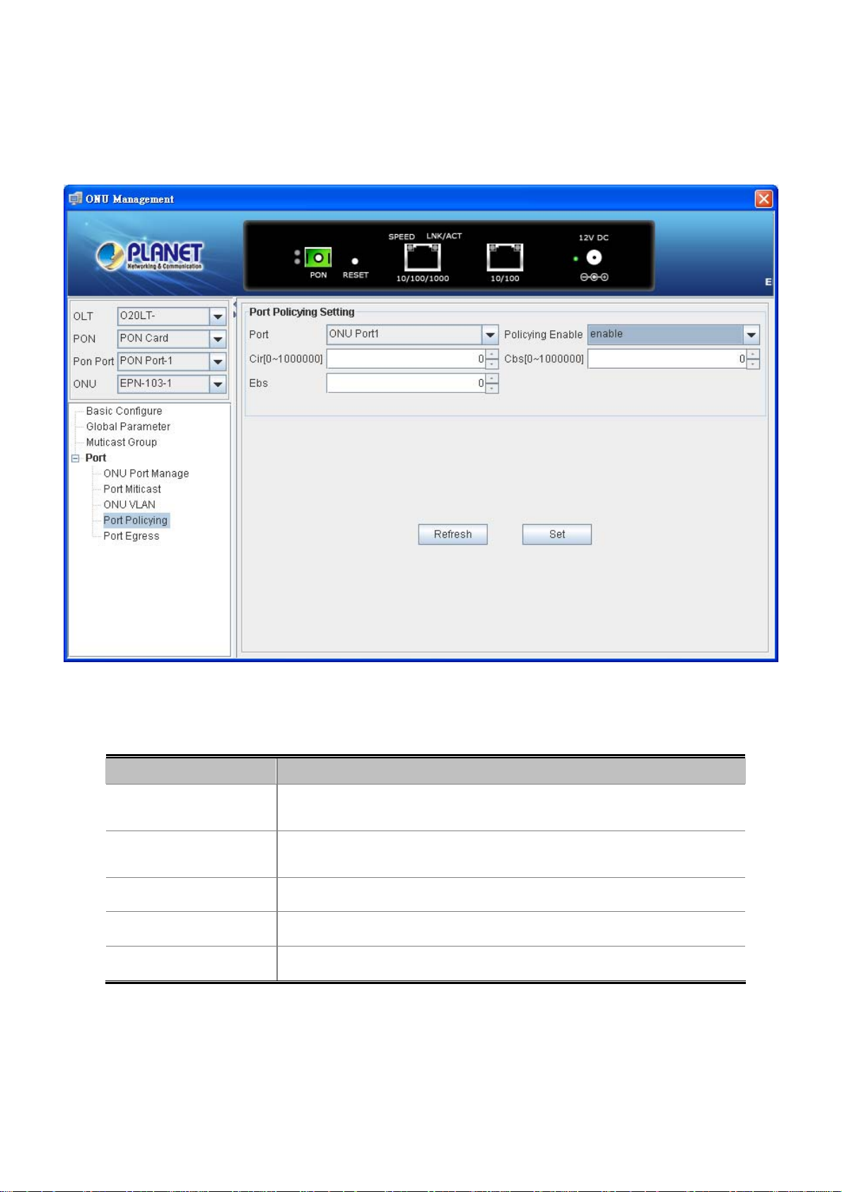
4.4.7 Port Policying
This page allows user to modify the Port Policy configuration.
User’s Manual of EPL-2000
The window includes the following fields:
Object Description
Port:
Policy Enable :
Cir[0-1000000]:
Cbs[0-1000000]:
Ebs:
ONU Port1: 10/100/1000Mbps Port.
ONU Port2: 10/100Mbps Port.
Allows user Disable or Enable the Policy mode.
Allows user to fill the Cir value, the range 0~1000000.
Allows user to fill the Cbs value, the range 0~1000000.
Allows user to fill the Ebs value.
Figure 4-46 Port Policying Screen
72
Page 73

4.4.8 Port Egress
This page allows user to modify the Port Egress configuration.
User’s Manual of EPL-2000
The window includes the following fields:
Object Description
Port:
Egress Enable :
Egress Cir[0-1000000]:
Egress Pir[0-1000000]:
ONU Port1: 10/100/1000Mbps Port.
ONU Port2: 10/100Mbps Port.
Allows user Disable or Enable the Egress mode.
Allows user to fill the Egress Cir value, the range 0~1000000.
Allows user to fill the Egress Pir value, the range 0~1000000.
Figure 4-47 Port Egress Screen
73
Page 74

User’s Manual of EPL-2000
4.5 How to upgrade EPL-2000 firmware
For upgrading the EPL-2000 firmware, you need to have FTP server software. Here we are using Home FTP Server software for
an example:
1. The following main screen of Home FTP Server appears:
Figure 4-48 Home FTP Server Main Screen
2. Press the “New account” on the left column and the FTP Client Editor window appears below like. Please fill in the user
name and password as “user”.
Figure 4-49 FTP Client Editor Screen
74
Page 75

User’s Manual of EPL-2000
3. Excute “Start Server” for making connection establish.
4. Copy the EPL-2000 firmware to the Home Ftp server directory.
For example: C:\Program Files\Home Series\Home Ftp Server
5. Operate EMS utility click EPL-2000 once excute “Device Upgrade” on the EMS toolbar of Config.
Figure 4-50 EPL-2000 Interface Screen
Figure 4-51 Device Upgrade Item Screen
75
Page 76
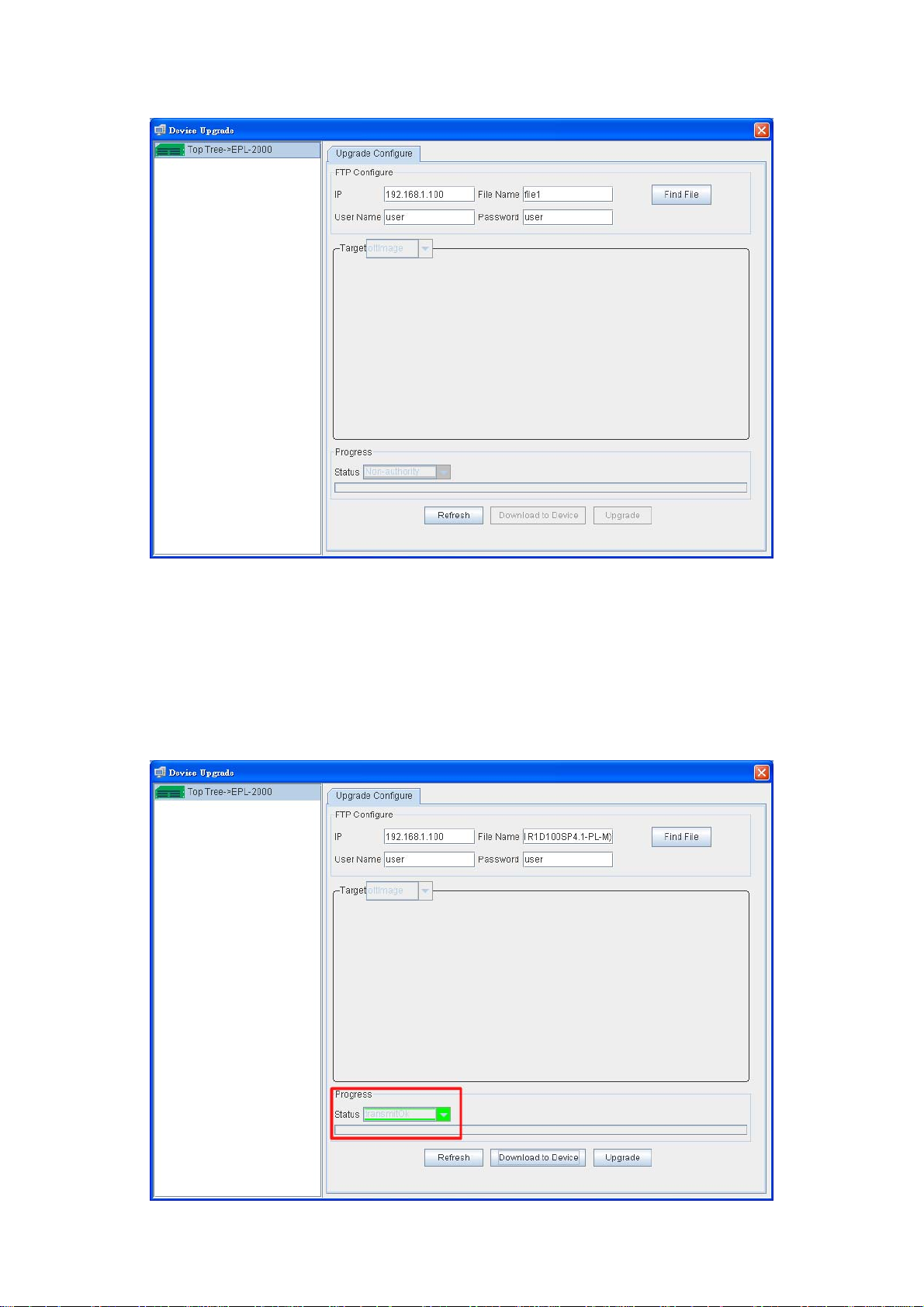
User’s Manual of EPL-2000
6. After executing the Device Upgrade, the following window will appear. Please fill in the user name and password as “user”.
Figure 4-52 Device Upgrade Procedure (1) Screen
7. Press “Find File” button to get EPL-2000 firmware. Following Step 3, the file should be at “C:\Program Files\Home
Series\Home Ftp Server”.
8. Press “Download to Device” button for downloading the firmware. After a couple of seconds, the Progress Status
“TransmitOK” will appear like the window below:
Figure 4-53 Device Upgrade Procedure (2) Screen
76
Page 77

User’s Manual of EPL-2000
9. Press “Upgrade” button for upgrading the firmware. During the period, the Progress Status will show “Upgrading”. After
finishing the upgrading, the Progress Status will show “Upgrade OK”.
Figure 4-54 Device Upgrade Procedure (3) Screen
Figure 4-55 Device Upgrade Procedure (4) Screen
10. After finishingh the firmware upgrade, please reboot the EPL-2000.
77
Page 78

User’s Manual of EPL-2000
5. EPL-2000 OPERATION
5.1 Address Table
The OLT switch is implemented with an address table. This address table os composed of many entries. Each entry is used to
store the address information on some nodes on the network, including MAC address, port number, etc.
5.2 Learning
When one packet comes in from any port, the OLT Switch will record the source address, port number, and other related
information in the address table. This information will be used to decide either forwarding or filtering for future packets.
5.3 Forwarding & Filtering
When one packet comes from some port of the Ethernet Switching, it will also check the destination address besides the source
address learning. The OLT Switch will look up the address table for the destination address. If not found, this packet will be
forwarded to all the other ports except the port, which this packet comes in. And these ports will transmit this packet to the
network it connected. If found, and the destination address is located at a different port from this packet comes in, the OLT
Switch will forward this packet to the port where this destination address is located according to the information from the
address table. But, if the destination address is located at the same port with this packet that comes in, then this packet will be
filtered, thereby increasing the network throughput and availability
5.4 Auto-Negotiation
The STP ports on the Switch have built-in "Auto-negotiation". This technology automatically sets the best possible bandwidth
when a connection is established with another network device (usually at Power On or Reset). This is done by detecting the
modes and speeds at the second of both devices are connected and capable of. Both 10BASE-T and 100BASE-TX devices can
connect with the port in either Half- or Full-Duplex mode.
If attached device is: 100Base-T X p ort will set to:
10Mbps, no auto-negotiation 10Mbps.
10Mbps, with auto-negotiation 10/20Mbps (10BASE-T/Full-Duplex)
100Mbps, no auto-negotiation 100Mbps
100Mbps, with auto-negotiation 100/200Mbps (100BASE-TX/Full-Duplex)
78
Page 79

A.1 Switch's RJ45 Pin Assignments
1000Mbps, 1000BASE-T
Contact MDI MDI-X
1 BI_DA+ BI_DB+
2 BI_DA- BI_DB-
3 BI_DB+ BI_DA+
4 BI_DC+ BI_DD+
5 BI_DC- BI_DD-
6 BI_DB- BI_DA-
7 BI_DD+ BI_DC+
User’s Manual of EPL-2000
APPENDIX A
8 BI_DD- BI_DC-
Implicit implementation of the crossover function within a twisted-pair cable, or at a wiring panel, while not expressly forbidden,
is beyond the scope of this standard.
A.2 10/100Mbps, 10/100BASE-TX
When connecting your 10/100Mbps Ethernet Switch to another switch, a bridge or a hub, a straight or crossover cable is
necessary. Each port of the Switch supports auto-MDI/MDI-X detection. That means you can directly connect the Switch to any
Ethernet devices without making a crossover cable. The following table and diagram show the standard RJ45 receptacle/
connector and their pin assignments:
RJ45 Connector pin assignment
Contact MDI
Media Dependent Interface
MDI-X
Media Dependent
Interface-Cross
1 Tx + (transmit) Rx + (receive)
2 Tx - (transmit) Rx - (receive)
3 Rx + (receive) Tx + (transmit)
4, 5 Not used
6 Rx - (receive) Tx - (transmit)
7, 8 Not used
79
Page 80

User’s Manual of EPL-2000
The standard cable, RJ45 pin assignment
The standard RJ45 receptacle/connector
There are 8 wires on a standard UTP/STP cable and each wire is color-coded. The following shows the pin allocation, color of
straight cable and crossover cable connection:
Straight Cable SIDE 1 SIDE 2
12345678
12345678
Crossover Cable SIDE 1 SIDE 2
12345678
12345678
SIDE 1
SIDE 2
SIDE 1
1 = White / Orange
2 = Orange
3 = White / Green
4 = Blue
5 = White / Blue
6 = Green
7 = White / Brown
8 = Brown
1 = White / Orange
2 = Orange
3 = White / Green
4 = Blue
5 = White / Blue
6 = Green
7 = White / Brown
1 = White / Orange
2 = Orange
3 = White / Green
4 = Blue
5 = White / Blue
6 = Green
7 = White / Brown
8 = Brown
1 = White / Green
2 = Green
3 = White / Orange
4 = Blue
5 = White / Blue
6 = Orange
7 = White / Brown
SIDE 2
Figure A-1: Straight-through and Crossover Cables
Please make sure your connected cables are with the same pin assignment and color as the above diagram before deploying
the cables into your network.
80
8 = Brown
8 = Brown
Page 81

EC Declaration of Conformity
For the following equipment:
*Type of Product :
*Model Number :
* Produced by:
Manufacturer‘s Name: Planet Technology Corp.
Manufacturer‘s Address: 10F., No.96, Minquan Rd., Xindian Dist.,
New T a ipei City 231, Taiwan (R.O.C.)
is herewith confirmed to comply with the requirements set out in the Council Directive on the
Approximation of the Laws of the Member States relating to Electromagnetic Compatibility
(2004/108/EC).
For the evaluation regarding the Electromagnetic Compatibility, the following standards were
applied:
EN 55022 (2010)
EN 61000-3-2 (2006 + A2: 2009)
EN 61000-3-3 (2008)
EN 55024 (2010)
EN 61000-4-2 (2009)
EN 61000-4-3 (2006 + A1: 2008)
EN 61000-4-4 (2004)
EN 61000-4-5 (2006)
EN 61000-4-6 (2009)
EN 61000-4-8 (2010)
EN 61000-4-11 (2004)
Responsible for marking this declarati o n i f the:
GEPON OLT
EPL-2000
Manufacturer Authorized representative established within the EU
Authorized representative established within the EU (if applicable):
Company Name: Planet Technology Corp.
Company Address: 10F., No.96, Minquan Rd., Xindian Dist., New Taipei City 231, Taiwan
Person responsible for making this declaration
Name, Surname Kent Kang
Position / Title : Pr oduct Manager
(R.O.C.)
Taiwan
16nd Nov., 2012
Place Date Legal Signature
PLANET TECHNOLOGY CORPORATION
e-mail: sales@planet.com.tw http://www.planet.com.tw
10F., No.96, Minquan Rd., Xindian Dist., New Taipei City, Taiwan, R.O.C. Tel:886-2-2219-9518 Fax:886-2-2219-9528
 Loading...