

Page 1

IMPORTANT FOR FUTURE REFERENCE
Please complete this information and retain this manual
for the life of the equipment:
Model #: ___________________________
Serial #: ___________________________
Date Purchased: ____________________
Service Manual
I8 Water Cooker Computer
Covering (P/N PP11375)
1 2 3 4 5 6 7 8
ENGLISH
0 9
This manual details the operation and adjustment of the I8 Water Cooker computer developed for
the Pitco water cooker and rethermalizer products. This microprocessor control offers the latest
cooking technology, including temperature and time compensation that requires no user
adjustments for consistently cooked product. Other features include, drain valve interlock, faulty
probe detection, selectable melt cycles, beeper volume, and cook temperature. Each product key
may be programmed with cook, shake and hold times to keep pace with changing menus over time.
This manual reveals all adjustments that are possible by keyboard entry, including passwords.
The target audience for this manual is the Service Technician.
L22-303 Rev 0 (01/07)
Page 2

I8 Water Cooker Computer Service
Pitco P/N PP11375
Table of Contents
1.0 Key Locations and Functions: 4
1.1 To turn the appliance ON: 4
1.2 To turn the appliance OFF: 4
1.3 To start a cook: 4
1.4 To cancel a cook: 4
1.5 To Check Actual and Set Temperatures: 4
1.6 To view the current Cook, Shake and Hold timer settings: 5
2.0 To enter Level 1 Programming(store manager): 5
2.1 To set the cook Temperature: 5
2.2 To change Cook, Shake and Hold timer settings: 5
2.2.1 Cook Time: 5
2.2.2 Shake Time: 6
2.2.3 Hold Time: 6
3.0 To enter Level 2 Options Programming(store manager): 6
3.1 Fahrenheit or Celsius Temperature Display: 7
3.2 Password Settings: 7
3.3 Beeper Volume Setting: 7
3.4 Language Selection: 7
3.5 Control or Timer Mode Setting: 8
4.0 To enter Level Service Programming(service technician): 8
4.1 Offset Temperature Setting: 8
4.2 Cancel Delay Setting: 9
4.3 Minimum On Cycle Time Setting: 9
4.4 Cancel Type Setting: 9
4.5 Diagnostics Menu: 9
4.5.1 Left Basket Lift (LBL) Output: 10
4.5.2 Right Basket Lift (RBL) Output: 10
4.5.3 Heat Demand (HD) Output: 10
4.5.4 Side On (SO) or Transfer Output: 10
4.5.5 Drain Switch (DVI) Input: 10
4.5.6 Heat Feedback (HFB) Input: 10
4.5.7 Fill Done Input: 10
2 L22-303 Rev 0 (01/07)
Page 3

I8 Water Cooker Computer Service
Pitco P/N PP11375
4.6 Recovery Test Value: 11
4.7 More Service Menu Options 11
4.7.1 Low Ready Level Adjustment: 11
4.7.2 High Ready Level Adjustment: 11
4.7.3 Low Dead Band Adjustment: 12
4.7.4 High Dead Band Adjustment: 12
4.7.5 Control Temperature Average Setting: 12
4.7.6 Display Temperature Average Setting: 12
4.7.7 Minimum Fill Time Setting: 13
4.7.8 Pilot Flame Sense Timer Adjustment: 13
5.0 Control Alarm Displays: 13
5.1 Open Probe Alarm: 13
5.2 High Temperature Alarm: 14
5.3 Drain Valve Alarm: 14
5.4 Heat Failure Alarm: 14
5.5 System Failure Alarm: 14
6.0 Electrical Connections(J1): 15
7.0 Probe Resistance Chart: 16
8.0 Physical Dimensions: 17
L22-303 Rev 0 (01/07) 3
Page 4
I8 Water Cooker Computer Service
Pitco P/N PP11375
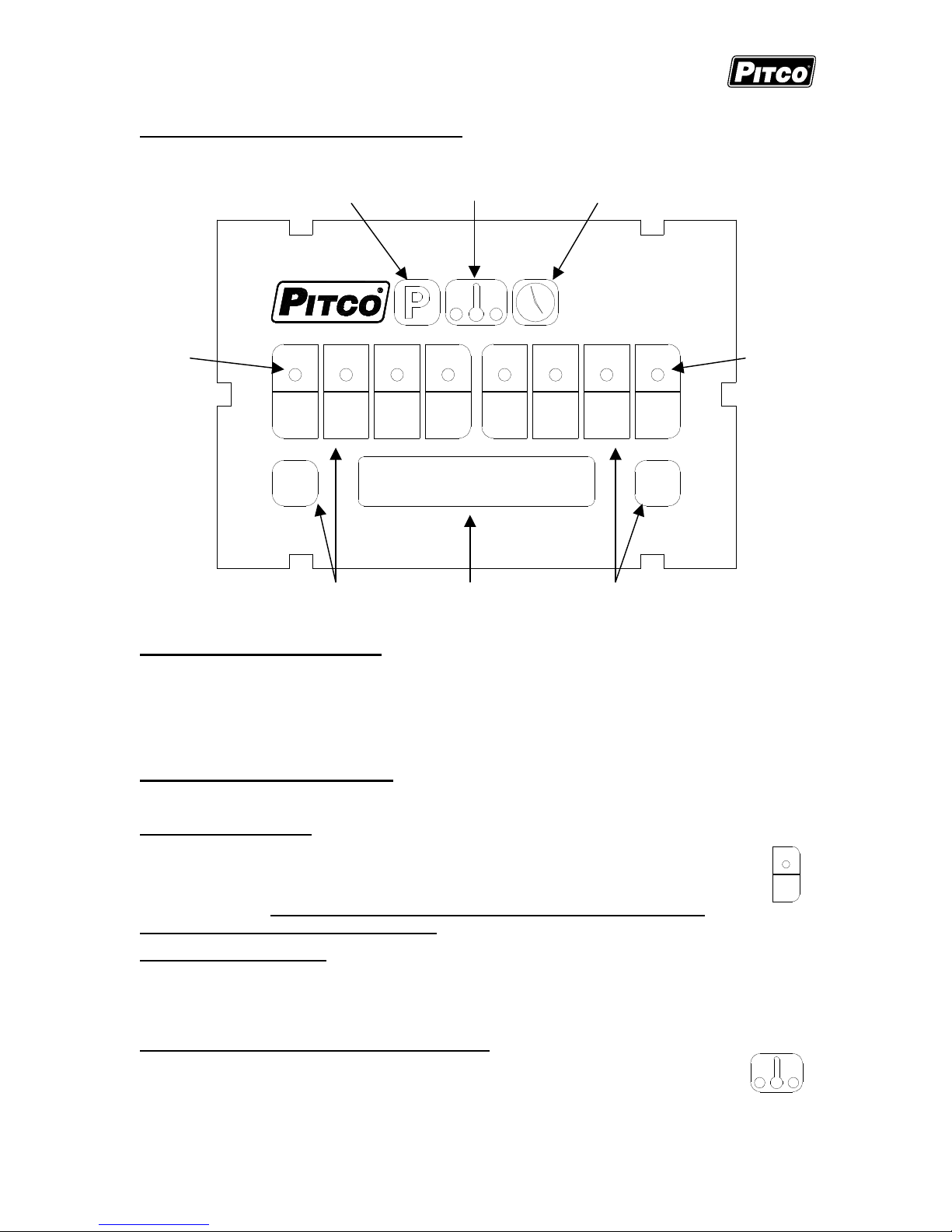
1.0 Key Locations and Functions:
Program Key Temperature Key Clock Key
Key Indicators Key Indicators
1 2 3 4 5 6 7 8
0 9
Product Keys 8 Digit Display Product Keys
1.1 To turn the appliance ON:
If power is applied to the appliance(plugged in) and the control is off, the display will be blank.
Turn on the control by pressing the power on/off switch located on the right side of the control to
the ON position. The control will then briefly display the software version number, and then
display either [READY], [ACT xxx’F] (where xxx is the current vat temperature) or [FILLING] if
the appliance is being filled with water.
1.2 To turn the appliance OFF:
Press the power on/off switch to the OFF position. The control display will be blank.
1.3 To start a cook:
When the control display shows either [READY] or [ACT xxx’F], press the desired
product key. For example, press product key 4 to start cook timer 4. The key indicator
above the product key will begin to flash, and the cook timer should appear on the
computer display. If multiple cook timers are running, the cook timer with the least
amount of time remaining will be displayed.
1.4 To cancel a cook:
Press the product key to cancel a running cook timer. If there are no other cook timers running,
the computer will return to normal operation and display either [READY] or [ACT xxx’F] (where
xxx is the current vat temperature).
1.5 To Check Actual and Set Temperatures:
Press the temperature key to check the actual vat temperature. The control will
momentarily display [ACT xxx’F] (where xxx is the current vat temperature) and then
return to normal operation.
4 L22-303 Rev 0 (01/07)
4
Page 5

I8 Water Cooker Computer Service
Pitco P/N PP11375
To view the set temperature, press the thermometer key twice. The control
will momentarily display [SET xxx’F] (where xxx is the set temperature),
and then return to normal operation and display either [READY], or
[ACT xxx’F].
1.6 To view the current Cook, Shake and Hold timer settings:
To view the current Cook, Shake and Hold timer settings for a cook timer, press
the clock key, followed by the desired product key for which you want to check the
time settings. For example, press the clock key, then product key 4.
The control will display [TM4 mm:ss] (where mm:ss is minutes:seconds), then [SH4 mm:ss]
and [HD4 mm:ss] as the current time settings for product key 4.
2.0 To enter Level 1 Programming(store manager):
Note: The factory default setting for this control does not require an operator password to be
entered. However, the operator password requirement and value may be changed in section
3.2. Entry of a password when NOT required will not interfere with the programming process.
4
While there are no cook timers running, and the control display shows either [READY],
[ACT xxx’F], or [FILLING ], press the program key. If the control displays [PASS ],
enter the manager password(or the default manager password 6684) using the product
keys 0-9. The control display will show [PROGRAM ].
All of the Level 1Menu programming options shown below must begin with the control displaying
this prompt [PROGRAM ].
2.1 To set the Cook Temperature:
With the control display showing [PROGRAM], press the thermometer key once. The
control display will show [SET xxx’F] where xxx is the current setpoint temperature.
Enter the new set temperature using the product keys 0-9. Press the program key
once to save this setting. The control display will show [PROGRAM ]. Continue on
to the next Level 1 Menu programming option below, or press the program key again
to exit it out of the Level 1 Menu. The control display will show either [READY], [ACT xxx’F], or
[FILLING ] and the control will return to normal operation.
2.2 To change Cook, Shake and Hold Timer settings:
2.2.1 Cook Time
With the control display showing [PROGRAM], press the clock key. The
display will show [SELECT] and all eight key indicators will light up. Press the
desired product key for the cook time to change. For example, press product
key 4. The control display will show [4TM mm:ss], indicating that Cook Timer 4
4
has a timer setting of mm:ss in minutes:seconds. Enter the new cook time
using the product keys 0-9. Press the clock key to save/exit this setting and
proceed to the next step(2.2.2) or press the program key three times to exit out of this
programming option and to return to normal operation.
L22-303 Rev 0 (01/07) 5
Page 6

I8 Water Cooker Computer Service
Pitco P/N PP11375
To deactivate the cook timer on a product key, enter in a cook time of zero for this key.
2.2.2 Shake Time
Shake Time is an alarm that sounds while a cook timer is running to prompt an operator
to shake the product in the basket. The default value for shake time on a product key is
zero, which disables this alarm. To enable the shake time alarm, a non-zero value must
be entered for this setting. The shake time value must be less than the cook time.
With the display showing [nSH mm:ss] (where n is the desired product key, SH means
Shake and mm:ss is the time value in minutes:seconds), enter the new shake time
value using the product keys 0-9. NOTE: the time value entered will be the time
remaining before the end of the cook.
Press the clock key to save/exit this setting and proceed to the next step(2.2.3)
or press the program key three times to exit out of this programming option and
return to normal operation.
2.2.3 Hold Time
After a product is cooked, it may stand in bins for a period of time. Hold Time provides a
timer to control how long a product stands in a bin. After the hold timer expires, an
alarm will sound to inform the operator to cook more product. The default value for hold
time on a product key is zero, which disables this alarm/timer. To enable the hold
timer/alarm, a non-zero value must be entered for this setting.
With the display showing [nHDh.mm:ss] (where n is the desired product key, HD
means Hold and h.mm:ss is the time value in hours.minutes:seconds), enter
the new hold time value using the product keys 0-9. Press the program key
three times to save and exit out of this programming option. The control
display will show either [READY], [ACT xxx’F], or [FILLING ] and the control will return
to normal operation.
3.0 To enter Level 2 Options Programming(store manager):
Note: The factory default setting for this control does not require an operator password to be
entered. However, the operator password requirement and value may be changed in section
3.2. Entry of a password when NOT required will not interfere with the programming process.
While there are no cook timers running, and the control display shows either [READY],
[ACT xxx’F], or [FILLING ], press the program key. If the control displays [PASS ],
enter the manager password(or the default manager password 6684) using the product
keys 0-9. The control display will show [PROGRAM ]. To enter into the Level 2 Options
Menu, press product key 0. The control display will show [SELECT ].
The key indicators that light up will have options that can be adjusted. Any key
indicators that do not light up do not have options that can be adjusted.
All of the Level 2 Options Menu programming options shown below must begin with the control
displaying this prompt [SELECT ].
0
6 L22-303 Rev 0 (01/07)
Page 7

I8 Water Cooker Computer Service
Pitco P/N PP11375
3.1 Fahrenheit or Celcius Temperature Display:
This control will display temperatures in Fahrenheit(ºF).or Celsius(ºC) degrees. The default
setting is degrees Fahrenheit(ºF).
With the control display showing [SELECT ], press product key 1. The display will show
1
[DEGREE n] where n is the current setting, either F or C. Press the 0 key to scroll
between the two options. Press the program key to save the setting. The control display
will show [PROGRAM ]. Press product key 0 to select more options below(display shows
[SELECT ]) or press the program key to return to normal operations(display shows either
[READY], [ACT xxx’F], or [FILLING ]).
3.2 Password Settings:
The factory default setting for this control is password disabled. The default factory password for
Level 1 and Level 2 programming is 6684. This default password will always work, regardless of
the new password that can be entered using this option.
With the control display showing [SELECT ], press product key 2. The display will show
2
[SET PASS]. Press product key 0 to scroll between the two options [PASS REQ], and
[NO PASS ]. Press the program key to save this setting. If the [NO PASS ] option was
selected, the control display will show [PROGRAM ]. ]. Press product key 0 to select
more options below(display shows [SELECT ]) or press the program key to return to normal
operations(display shows either [READY], [ACT xxx’F], or [FILLING ]). If the [PASS REQ]
option was selected, the display will show [PASSxxxx], where xxxx is the current password.
Enter the new password using the product keys 0-9. Press the program key. The control
display will show [PROGRAM ]. Press product key 0 to select more options below(display shows
[SELECT ]) or press the program key to return to normal operation(display shows either
[READY], [ACT xxx’F], or [FILLING ]).
3.3 Beeper Volume Setting:
The volume setting of the beeper(alarm) can be set to low(1), medium(2) and high(3). The
default value for the beeper volume is 3.
With the control display showing [SELECT ], press product key 3. The display will show
[VOLUME x] where x is the current volume setting. Press product key 0 to scroll through
the volume options. The control will beep using the volume setting currently shown on the
display. Press the program key to save this setting. The control display will show
[PROGRAM ]. Press product key 0 to select more options below(display shows [SELECT ]) or
press the program key to return to normal operation(display shows either [READY], [ACT
xxx’F], or [FILLING ]).
3.4 Language Selection:
This control can display text in English, Spanish, French, German and Dutch.
With the control display showing [SELECT ], press product key 4. The display will show
the current language setting of either [ENGLISH], [ESPANOL], [FRANCAIS],
[DEUTSCH], or [HOLLANDS]. Press product key 0 to scroll through the language
options. Press the program key to save this setting. The control display will show
[PROGRAM ]. Press product key 0 to select more options below(display shows [SELECT ]) or
press the program key to return to normal operation(display shows either [READY], [ACT
xxx’F], or [FILLING ]).
3
4
L22-303 Rev 0 (01/07) 7
Page 8

I8 Water Cooker Computer Service
Pitco P/N PP11375
3.5 Control or Timer Mode Setting:
This control can operate in one of two basic modes, Control or Timer mode. The default mode
setting is Control mode, and is the setting for normal operation. In this mode, the cook timers
are active and the heat control outputs are enabled to control the heating of the vat. In Timer
mode, the cook timers are active, but the heat control outputs are disabled.
NOTE: Do not use the Timer mode setting on Solstice fryer models.
With the control display showing [SELECT ], press product key 7. The display will show
the current setting of either [CONTROL ] or [TIMER ]. Press product key 0 to scroll
between the two options. Press the program key to save this setting. The control display
will show [PROGRAM ]. Press product key 0 to select more options below(display shows
[SELECT ]) or press the program key to return to normal operation(display shows either
[READY], [ACT xxx’F], or [FILLING ]).
4.0 To Enter Level 3 Service Programming(service technician):
Note: The factory default setting for this control does not require an operator password to be
entered. However, the operator password requirement and value may be changed in section
3.2. Entry of a password when NOT required will not interfere with the programming process.
7
While there are no cook timers running, and the control display shows either [READY],
[ACT xxx’F], or [FILLING ], press the program key. If the control displays [PASS ],
enter the manager password(or the default manager password 6684) using the product
8
keys 0-9. The control display will show [PROGRAM ]. To enter into the Level 3
6
5
6
Service Menu, key in the service password of 6685 using the product keys 0-9.
The control display will show [SERVICE ].
The key indicators that light up will have options that can be adjusted. Any key indicators that do
not light up do not have options that can be adjusted.
All of the Level 3 Service Menu programming options shown below must begin with the control
displaying this prompt [SERVICE ].
4.1 Offset Temperature Setting:
This setting allows the displayed temperature value to be offset(degrees F) to reflect the true
center vat temperature while reading the probe tip temperature. The default value is zero. A
setting of zero for the temperature offset will make the displayed temperature equal to the probe
temperature. The maximum offset value that can be entered is 20.
With the control display showing [SERVICE ], press product key 1. The display will show
1
[OFF xx F], where xx is the current offset value. Enter the new offset value using the
product keys 0-9. Press the program key to save this setting. The control display will
show either [POSITIVE] or [NEGATIVE], indicating that the offset value is positive or negative.
Press product key 0 to scroll between these two options. Press the program key to save this
setting. The display will now show [SERVICE ]. Continue on to the remaining service menu
options below, or press the program key twice to return to normal operation(display shows either
[READY], [ACT xxx’F], or [FILLING ]).
8 L22-303 Rev 0 (01/07)
Page 9

I8 Water Cooker Computer Service
Pitco P/N PP11375
4.2 Cancel Delay Setting:
This setting controls the length of time(in seconds) necessary for a key press to cancel an active
cook timer. A setting of zero disables this cancel delay setting and a cook timer cancels as soon
as a product key is pressed. A cancel delay setting of greater than zero enables this cancel
delay, and a product key must be pressed and held for the duration of time(in seconds) equal to
the current cancel delay before the active cook timer will cancel. For example, if the cancel
delay is set to 5, then a product key will have to be pressed and held for 5 seconds before the
active cook timer will cancel. The default value is zero. The maximum value that can be
entered is 9.
NOTE: The Cancel Type(section 4.4) must be set to 1 before this Cancel Delay feature will
work. See section 4.4, Cancel Type Setting, for more information.
With the control display showing [SERVICE ], press product key 2. The display will show
2
[CAN DLYx], where x is the current cancel delay value. Enter the new cancel delay using
product keys 0-9. Press the program key to save this setting. The display will now show
[SERVICE ]. Continue on to the remaining service menu options below, or press the
program key twice to return to normal operation(display shows either [READY], [ACT xxx’F], or
[FILLING ]).
4.3 Minimum On Cycle Time Setting:
This setting adjusts the minimum time duration(in seconds) that the heat control output will be on
when heat is applied to the vat. The range of this setting is 1 – 30 seconds.
With the control displaying [SERVICE ], press product key 3. The display will show
3
[MINON :xx], where xx is the current minimum on cycle time(in seconds). Enter the new
value using product keys 0-9. Press the program key to save this setting. The display will
now show [SERVICE ]. Continue on to the remaining service menu options below, or press the
program key twice to return to normal operation (display shows either [READY], [ACT xxx’F], or
[FILLING ]).
4.4 Cancel Type Setting:
The Cancel Type setting allows for two cook timer cancellation types. If set to 1, then the
Cancel Delay setting(section 4.2) is used. If the Cancel Type is set to 0, then a product key
must be pressed three times in succession in order to cancel a cook, and the Cancel Delay
setting is ignored. The default Cancel Type value is 1.
With the control display showing [SERVICE ], press product key 4. The control display will
4
show [CANTYP x], where x is the current cancel type value, either 0 or 1. Press product
key 0 to scroll between the two cancel type values. Press the program key to save this
setting. The display will now show [SERVICE ]. Continue on to the remaining service
menu options below, or press the program key twice to return to normal operation(display shows
either [READY], [ACT xxx’F], or [FILLING ]).
4.5 Diagnostics Menu:
This menu option allows for basic diagnostic testing of the inputs and outputs of the control. By
exercising outputs and examining inputs, a determination can be made as to whether the
appliance problem is related to the control computer. In this menu, each product key is assigned
to a specific input or output on the control.
All control outputs in the ON state should produce 24VDC(+/- 10%) on the appropriate pin on the
controller connector. All controller inputs require 24VAC or 24VDC(+/- 10%) on the appropriate
L22-303 Rev 0 (01/07) 9
Page 10

I8 Water Cooker Computer Service
Pitco P/N PP11375
connector pin. Controller inputs can be verified by the ON or OFF state of the key indicator
above the appropriate product key.
With the control display showing [SERVICE ], press product key 5 to enter into the
diagnostics menu. The control display will show either [D CLOSED] or [D OPEN]
depending on whether the drain switch is open or closed. Press the appropriate product
key listed below to test the input/output assigned to that key:
5
4.5.1 Left Basket Lift(LBL) Output:
Press product key 1 to toggle this output ON or OFF. The control display
will show [L BASKET].
4.5.2 Right Basket Lift(RBL) Output:
Press product key 2 to toggle this output ON or OFF. The control display
will show [R BASKET].
4.5.3 Heat Demand(HD) Output:
Press and hold product key 3 to turn this output ON. Release the key to
turn this output OFF. The control display will show [HEAT DEM].
4.5.4 Side On(SO) or Transfer Output:
Press product key 4 to toggle this output ON or OFF. The control display
will show [TRANSFER].
4.5.5 Drain Switch(DVI) Input:
Press product key 5 to view the state of the drain switch input. The
control display will show either [D CLOSED] or [D OPEN] depending on
whether the drain switch is open or closed.
1
2
3
4
5
4.5.6 Heat Feedback(HFB) Input:
Press product key 7 to view the state of the heat feedback input. The
control display will show either [FB ON] or [FB OFF] depending on
whether a heat feedback signal is present or not.
4.5.7 Fill Done Input:
Press product key 8 to view the state of the fill done input. The control
will display either [NO FILL] or [FILL] depending on whether a fill signal
is present or not.
Press the program key to exit it out of this menu option. The display will now show
[SERVICE ]. Continue on to the remaining service menu options below, or press the
program key twice to return to normal operation(display shows either [READY],
[ACT xxx’F], or [FILLING ]).
10 L22-303 Rev 0 (01/07)
7
8
Page 11

I8 Water Cooker Computer Service
Pitco P/N PP11375
4.6 Recovery Test Value:
This control records the heat up time for the appliance. A poorly running appliance will have an
increased recovery time. Select this menu option to view the last recorded recovery time for this
appliance. The recovery time is the length of time(in seconds) the appliance needs to heat the
vat from 230°F to 280°F. This menu option is for display only.
With the control display showing [SERVICE ], press product key 7. The control display will
7
show [Rxxx-yyy], where xxx is the last recorded recovery time for this appliance, and yyy
is the factory default recovery time. Press the program key to exit it out of this menu
option. The display will now show [SERVICE ]. Continue on to the remaining service menu
options below, or press the program key twice to return to normal operation(display shows either
[READY], [ACT xxx’F], or [FILLING ]).
4.7 More Service Menu Options:
With the control display showing [SERVICE ], press product key 8. The display will show
8
[MORE ] for the More Service Menu.
The key indicators that light up will have options that can be adjusted. Any key indicators
that do not light up do not have options that can be adjusted.
All of the Level 3 More Service Menu programming options shown below must begin with the
control displaying this prompt [MORE ].
4.7.1 Low Ready Level Adjustment:
This setting allows the READY idle message to be displayed a number of degrees below
the current set temperature. For example, if the current set temperature is 180°F, and
the READY idle display message is to be displayed from 175°F to 180°F, then this
setting should be given a value of 5. The maximum value for this setting is 9 degrees.
With the control display showing [MORE ], press product key 1. The display will
now show [RDY LO x], where x is the current Low Ready Level setting. Enter the
new value using product keys 0-9. Press the program key to save this setting.
The display will now show [MORE ]. Continue on to the remaining more service
menu options below, or press the program key three times to return to normal
operation(display shows either [READY], [ACT xxx’F], or [FILLING ]).
4.7.2 High Ready Level Adjustment:
This setting allows the READY idle message to be displayed a number of degrees
above the current set temperature. For example, if the current set temperature is 180°F,
and the READY idle display message is to be displayed from 180°F to 185°F, then this
setting should be given a value of 5. The maximum value for this setting is 9 degrees.
With the control display showing [MORE ], press product key 2. The display will
now show [RDY HI x], where x is the current High Ready Level setting. Enter the
new value using product keys 0-9. Press the program key to save this setting.
The display will now show [MORE ]. Continue on to the remaining more service
menu options below, or press the program key three times to return to normal
operation(display shows either [READY], [ACT xxx’F], or [FILLING ]).
1
2
L22-303 Rev 0 (01/07) 11
Page 12

I8 Water Cooker Computer Service
Pitco P/N PP11375
4.7.3 Low Dead Band Adjustment:
This setting adjusts the vat temperature limit below the set temperature, where the heat
demand output will be ON to apply heat to the vat. At vat temperatures below this value,
heat will be applied to the vat. For example if the set temperature is 180°F, and the Low
Dead Band value is 3, then at vat temperatures below 177°F, heat will be applied to the
vat. The value range of this setting is 1 – 9 degrees
With the control display showing [MORE ], press product key 3. The display will
3
now show [DB LO x], where x is the current Low Dead Band value. Enter the
new value using product keys 1-9. Press the program key to save this setting.
The display will now show [MORE ]. Continue on to the remaining more service
menu options below, or press the program key three times to return to normal
operation(display shows either [READY], [ACT xxx’F], or [FILLING ]).
4.7.4 High Dead Band Adjustment:
This setting adjusts the vat temperature limit above the set temperature, where the heat
demand output will be OFF. At vat temperatures equal to or greater than this value, the
heat demand output will be OFF. For example if the set temperature is 180°F, and the
High Dead Band value is 1, then at vat temperatures at or above 181°F, heat will not be
applied to the vat. A setting of zero for this value will force the heat control output OFF
when the vat temperature equals the set temperature. The value range of this setting is
0 – 9 degrees.
With the control display showing [MORE ], press product key 4. The display will
4
now show [DB HI x], where x is the current High Dead Band value. Enter the
new value using product keys 0-9. Press the program key to save this setting.
The display will now show [MORE ]. Continue on to the remaining more service
menu options below, or press the program key three times to return to normal
operation(display shows either [READY], [ACT xxx’F], or [FILLING ]).
4.7.5 Control Temperature Average Setting:
This setting adjusts the number of times(per second) the vat temperature readings are
averaged in the heat control process of the computer. The default value for this setting
is 6. The value range of this setting is 1-9.
With the control display showing [MORE ], press product key 5. The display will
show [AVER C x], where x is the current control temperature average setting.
Enter the new value using product keys 1-9. Press the program key to save this
setting. The display will now show [MORE ]. Continue on to the remaining more
service menu options below, or press the program key three times to return to normal
operation(display shows either [READY], [ACT xxx’F], or [FILLING ]).
4.7.6 Display Temperature Average Setting:
This option adjusts the number of times(per second) the vat temperature readings are
averaged each second for displaying on the control display. The default value for this
setting is 12. The value range for this setting is 7 – 32.
With the control display showing [MORE ], press product key 6. The display will
show [AVER Dxx], where xx is the current display temperature average setting.
Enter the new value using product keys 0-9. Press the program key to save this
setting. The display will now show [MORE ]. Continue on to the remaining more
12 L22-303 Rev 0 (01/07)
5
6
Page 13

I8 Water Cooker Computer Service
Pitco P/N PP11375
service menu options below, or press the program key three times to return to normal
operation(display shows either [READY], [ACT xxx’F], or [FILLING ]).
4.7.7 Minimum Fill Time Setting:
This setting adjusts the minimum length of time the heat control process in the computer
will wait before applying heat to the vat when the vat is being filled with water. Heat will
be applied to the vat after the computer senses that the vat is full of water and the fill
time counter expires. The sensing of the water level in the vat takes precedence over
the fill time counter. In other words, the computer will ignore this timer if it does not
sense that the vat is full(if the timer expires before the vat is full). The default setting for
this timer is 20 minutes(20:00). The value range for this timer is from 1 – 30 minutes.
With the control display showing [MORE ], press product key 7. The display will
7
show [FILLmm:ss], where mm:ss is the current minimum fill time setting in
minutes:seconds. Enter the new timer value using product keys 0-9. Press the
program key to save this setting. The display will now show [MORE ]. Continue
on to the remaining more service menu option below, or press the program key three
times to return to normal operation(display shows either [READY], [ACT xxx’F], or
[FILLING ]).
4.7.8 Pilot Flame Sense Timer Adjustment:
This menu option adjusts the timer that is used by the control to detect an absence of a
pilot flame in the appliance during a cold start. During a cold start of the appliance, the
control will expect to sense a pilot flame before this timer times out. If on a cold start, a
pilot flame is not sensed by the control when this timer expires, the control outputs will
be turned OFF(heat will be turned off), and an alarm will sound. The default value for
this timer is 60 seconds. The value range of this setting is 10 – 60
With the control display showing [MORE ], press product key 8. The display will
show [FLAME xx], where xx is the current pilot flame sense timer value in
seconds. Enter the new value using product keys 0-9. Press the program key to
save this setting. The display will now show [MORE ]. Continue on to the other more
service menu options above, or press the program key three times to return to normal
operation(display shows either [READY], [ACT xxx’F], or [FILLING ]).
5.0 Control Alarm Displays:
This control continually monitors the basic overall functions of the appliance. If any
faults are detected, the control will turn all outputs OFF, suspend any cooking functions
that may be in progress and sound an alarm. One of several alarm messages detailed
below will appear on the control display. If one if these alarms occur, turn off the
control(see section 1.2). to reset the alarm.
8
5.1 Open Probe Alarm:
[PROBE OP]. Open temperature probe detection is standard on all Pitco controls. This
alarm will occur if the temperature probe is detected to be open. All heating and cooking
functions are suspended if this alarm occurs.
L22-303 Rev 0 (01/07) 13
Page 14

I8 Water Cooker Computer Service
Pitco P/N PP11375
5.2 High Temperature Alarm:
[HIGH TMP]. This alarm will occur if the vat temperature exceeds the set temperature
value by 35°F. If a high vat temperature alarm occurs, all heating and cooking functions
are suspended.
5.3 Drain Valve Alarm:
[DRAINING] and [TURN OFF] (alternating). This alarm message will appear on the
control display if the drain valve on the appliance is opened while the control is ON. All
heating and cooking functions are suspended if this alarm occurs.
5.4 Heat Failure Alarm:
[HEAT] and [FAILURE] (alternating). This alarm will occur if the control does not sense
a pilot flame or if the high limit switch has tripped and needs resetting. All heating and
cooking functions are suspended if this alarm occurs.
5.5 System Failure Alarm:
[SYSTEM]. This alarm will occur if the control detects a shorted temperature probe. All
heating and cooking functions are suspended if this alarm occurs.
14 L22-303 Rev 0 (01/07)
Page 15

I8 Water Cooker Computer Service
Pitco P/N PP11375
6.0 Electrical Connections(J1):
J1 Connection Type Nominal Notes:
1 24VAC IN PWR 24VAC 24VAC +20% / -15% 50/60Hz
2 24VAC COM PWR 0VAC AC RETURN
3 PROBE +
4 PROBE -
THERMISTOR
PROBE
Resistance varies with vat temperature. 6.22K
ohms at 212°F.
5 DVI INPUT 24VAC/DC Drain Valve Interlock
6 HFB INPUT 24VAC/DC Heat FeedBack
7 24VDC COM PWR 0VDC DC RETURN
8 HD OUTPUT 24VDC Heat Demand
9 SO(TRANSFER) OUTPUT 24VDC Side On(TRANSFER)
10 RBL OUTPUT 24VDC Right Basket Lift
11 LBL OUTPUT 24VDC Left Basket Lift
12 FILL DONE INPUT 24VAC/DC Fill Done signal
NOTE: The Diagnostics Menu(sections
4.0 and 4.5) can be used to check the
inputs and outputs on this connector.
6
12 9
11 8
10 7 4 1
3
5
2
J1
7 4
1
5
11108
12
L22-303 Rev 0 (01/07) 15
2
9 6 3
Page 16

I8 Water Cooker Computer Service
562734
175
79.4
11719
340
171.1
1058.23
271446
200
93.3
7586
365
185.0
795.10
Pitco P/N PP11375
7.0 Probe Resistance Chart:
Probe Resistance in 5°F Increments.
Probe
Temp
(°F)
Probe
Temp
(°C)
Resistance
(Ohms)
Probe
Temp
(°F)
Probe
Temp
(°C)
Resistance
(Ohms)
Probe
Temp
(°F)
Probe
Temp
(°C)
Resistance
(Ohms)
10 -12.2
15 -9.4 483875 180 82.2 10716 345 173.9 998.09
20 -6.7 417167 185 85.0 9812 350 176.7 942.00
25 -3.9 360589 190 87.8 8995 355 179.4 889.67
30 -1.1 312474 195 90.6 8255 360 182.2 840.78
35 1.7
40 4.4 236370 205 96.1 6979 370 187.8 752.38
45 7.2 206311 210 98.9 6427 375 190.6 712.41
50 10.0 180491 215 101.7 5926 380 193.3 674.95
55 12.8 158252 220 104.4 5470 385 196.1 639.87
60 15.6 139055 225 107.2 5055 390 198.9 606.96
65 18.3 122489 230 110.0 4675 395 201.7 576.09
70 21.1 108051 235 112.8 4329 400 204.4 547.09
75 23.9 95539 240 115.6 4013 405 207.2 519.86
80 26.7 84644 245 118.3 3723 410 210.0 494.24
85 29.4 75136 250 121.1 3458 415 212.8 470.16
90 32.2 66823 255 123.9 3214 420 215.6 447.49
95 35.0 59540 260 126.7 2991 425 218.3 426.13
100 37.8 53146 265 129.4 2785 430 221.1 406.02
105 40.6 47523 270 132.2 2597 435 223.9 387.04
110 43.3 42569 275 135.0 2422 440 226.7 369.14
115 46.1 38195 280 137.8 2262 445 229.4 352.24
120 48.9 34328 285 140.6 2113.9 450 232.2 336.29
125 51.7 30902 290 143.3 1977.3 455 235.0 321.21
130 54.4 27862 295 146.1 1851.0 460 237.8 306.94
135 57.2 25161 300 148.9 1734.3 465 240.6 293.46
140 60.0 22755 305 151.7 1626.1 470 243.3 280.69
145 62.8 20610 310 154.4 1525.9 475 246.1 268.61
150 65.6 18695 315 157.2 1433.0 480 248.9 257.15
155 68.3 16981 320 160.0 1346.7 485 251.7 246.30
160 71.1 15446 325 162.8 1266.6 490 254.4 236.00
165 73.9 14069 330 165.6 1192.1 495 257.2 226.24
170 76.7 12823 335 168.3 1122.8 500 260.0 216.96
NOTE: The resistance of either probe lead measured to the frame of the appliance should
read as an open on a meter(resistance >= 1Mohm).
16 L22-303 Rev 0 (01/07)
Page 17

8.0 Physical Dimensions:
I8 Water Cooker Computer Service
Pitco P/N PP11375
1 2 3 4 5 6 7 8
0 9
L22-303 Rev 0 (01/07) 17
Page 18

I8 Water Cooker Computer Service
Pitco P/N PP11375
NOTES:
____________________________________________________________________________
____________________________________________________________________________
____________________________________________________________________________
____________________________________________________________________________
____________________________________________________________________________
____________________________________________________________________________
____________________________________________________________________________
____________________________________________________________________________
____________________________________________________________________________
____________________________________________________________________________
____________________________________________________________________________
____________________________________________________________________________
____________________________________________________________________________
____________________________________________________________________________
____________________________________________________________________________
____________________________________________________________________________
____________________________________________________________________________
18 L22-303 Rev 0 (01/07)
Page 19

I8 Water Cooker Computer Service
Pitco P/N PP11375
NOTES;
____________________________________________________________________________
____________________________________________________________________________
____________________________________________________________________________
____________________________________________________________________________
____________________________________________________________________________
____________________________________________________________________________
____________________________________________________________________________
____________________________________________________________________________
____________________________________________________________________________
____________________________________________________________________________
____________________________________________________________________________
____________________________________________________________________________
____________________________________________________________________________
____________________________________________________________________________
____________________________________________________________________________
____________________________________________________________________________
____________________________________________________________________________
L22-303 Rev 0 (01/07) 19
Page 20

In the event of problems with or
questions about your order, please
contact the Pitco Frialator factory at
(800)258-3708 US and Canada only or
(603)225-6684 Worldwide.
www.pitco.com
MAILING ADDRESS: P.O. BOX 501, CONCORD, NH 03302-0501
SHIPPING ADDRESS: 10 FERRY ST., CONCORD, NH 03301
In the event of problems with or
questions about your equipment, please
contact the Pitco Frialator Authorized
Service and Parts(ASAP) covering your
area, or contact Pitco at the numbers
listed to the left.
L22-303 Rev 0 (01/07)
 Loading...