

Page 1
v
Page 2

MI'S , PF28-03
J
J
Pita> Frialator '1..20-086-01
Rev 00
Rev. Due 12117/93
Page 3
NonCES
There are three different types of noti~s that you should be familiar with, a NO11CE, CAunON,
and WARNING. A NO11CE is a special note used to call attention to a particularly important point
CAunON is used to point out a procedure or operation which may cause equipment damage. The
WARNING notice is the most important of the three because it warns of an operation that may cause
personal injury. Please familiarize yourself with your new rooter before operating it and heed the
notices throughout this manual. The WARNINGS are listed below and on the following page for
your review prior to operating the unit
~
Page 4
SAFETY
SAFETY
The fryer is equipped with an oil proof, electrical supply oord with a three
prong safety plug. This is to protect operators from electrical shock hazard
in the event of an equipment malfunction. DO NOT cut or remove the
grounding (dlird) prong from this plug.
SAFETY
SAFETY
~==I
There is an open flame inside the fryer. The unit may get hot enough to set
near by materials on file. Keep the area around the fryer free from combus-
tibles.
~==I
DO NOT supply the fryer with a gas that is DOt indicated on the data plate. If
you need to convert the fryer to another type of fuel, oontact your dealer.
SAFETY
DO NOT use an open flame to check for gas leaks!
Wait S minutes before attempting to relight the pilot to allow for any gas in
the fryer to dissipate.
1~:i~:~:~::::;;11I
Never melt blocks of shortening on
a fire, and void your warranty.
Water and shortening DO NOT mix. Keep liquids away from hot shortening.
Dropping liquid frozen food into the hot shortening will cause violent boiling.
At operating temperature the shortening temperature may be greater than
3OOoP. Extreme care should be used when filtering operating temperature
shortening to avoid personnel injury.
top of
;AFETY
~
~~~
~~~
SAFETY
SAFETY SAFETY
SAFETY
Page 5
SAFETY
S~FETY
It will be easier and safer if the filter assembly has oooled to room temperature
before handling any filter parts.
Ensure that the fryer can get enough air to keep the flame burning oorrectly.
If the flame is starved for air it can give off a dangerous carbon monoxide gas.
Carbon Monoxide is a clear odorless gas that can cause
A cooker equipped with casters and a flexible power cord, must be connected
to the gas supply with a Quick-Disconnect devi~. This quick disconnect
must comply with ANSI Z24.41. To limit the movement of the cooker
without depending on the connector or quick disconnect, a restraining cable
must also be installed.
S:AFETY
[:~:::;:::~:::;;;;III
SAFETY
suffocation.
S:AFETY
The power supply must be
applian~.
SAFETY
SAFETY
SAFETY
SAFETY
SAFETY
Page 6
Page 7
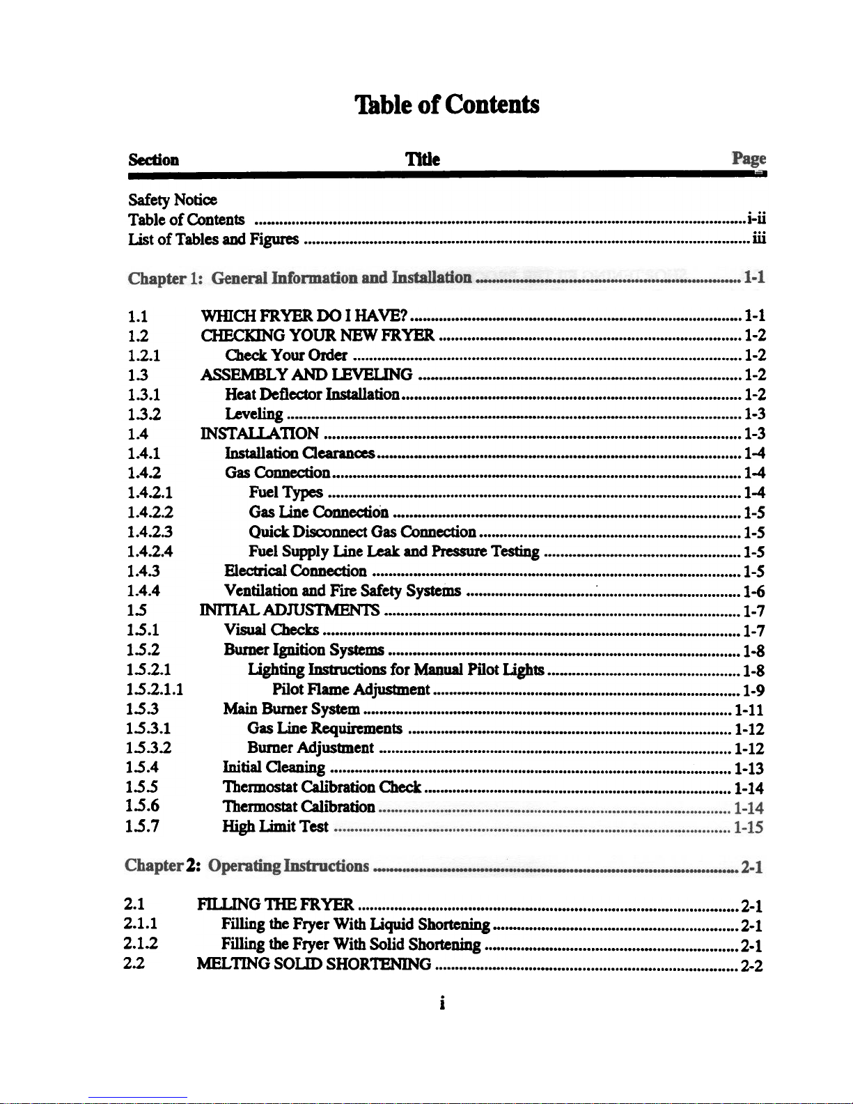
Table of Contents
Section
Safety Notice
Title
Table of Contents i-ii
Ust of Tables and Figures ill
1.1
1.2
1.2.1
1.3
1.3.1
1.3.2
1.4
1.4.1
1.4.2
1.4.2.1
1.4.2.2
1.4.2.3
1.4.2.4
1.4.3
1.4.4
1.5
1.5.1
1.5.2
1.5.2.1
1.5.2.1.1
1.5.3
1.5.3.1
1.5.3.2
1.5.4
1.5.5
1.5.6
1.5.7
WInCH FRYER DO I HAVE? 1-1
CHECKING YOUR NEW FRYER 1-2
Cleck Your Order 1-2
ASSEMBLY AND LEVEUNG 1-2
Heat Deflector In..ct31lation 1-2
Leveling 1-3
INST AUA 110 N ... 1-3
Installation Clearan~ 1-4
Gas Connection 1-4
Fuel Types 1-4
Gas Line Connection 1-5
Quick Disconnect Gas Connection 1-5
Fuel Supply Line Leak and Pressure Testing 1-5
Electrical Connection... ... ... 1-5
Ventilation and Fire Safety Systems ~ 1-6
INl11AL ADJUSTMENTS 1-7
Visual Checks 1-7
Burner Ignition Systems 1-8
lighting Instructions for Manual Pilot Lights 1-8
Pilot Flame Adjustment 1-9
Main Burner System 1-11
Gas Line Requirements 1-12
Burner Adjustment 1-12
Initial Cleaning 1-13
Thennostat Calibration Check 1-14
Thennostat Calibration
High Limit Test
-
2:
2.1
2.1.1
2.1.2
2.2
f1LLING nIB FRYER 2-1
Filling the Fryer With Liquid Shortening 2-1
Filling the Fryer With Solid Shortening 2-1
MELTING SOLID SHORTENING 2-2
i
Page 8
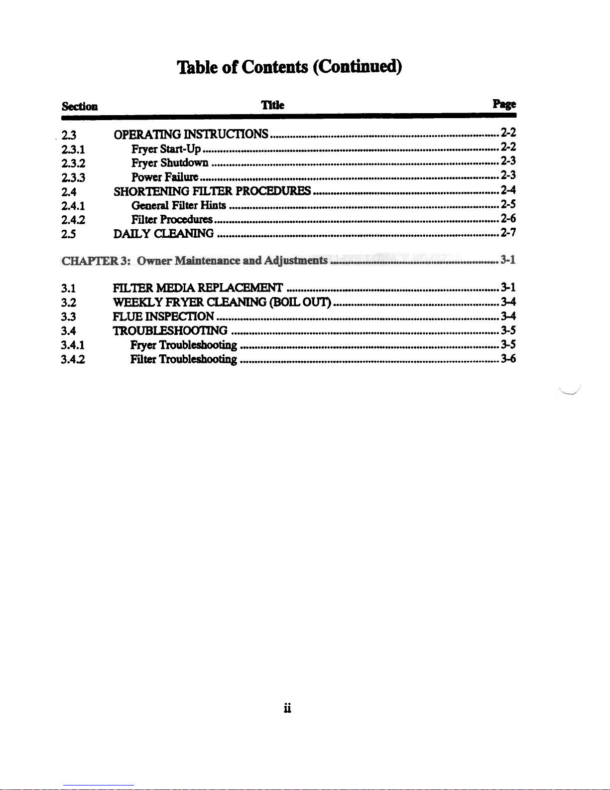
Table of Contents (Continued)
Section ntle Page
2.3 OPERA 11NG INSTR UcnONS 2-2
2.3.1 Fryer Start-Up 2-2
2.3.2 Fryer Shutdown 2-3
2.3.3 Power Failure ... ... " ..,.. 2-3
2.4 SHORTENING FILTER PROCEDURES .,.,." ,..",.,...,..." ,.., 2-4
2.4.1 General Filter Hints 2-5
2.4.2 Filter Procedures. 2-6
2.S DAn., Y CLEANING 2-7
3.1
3.2
3.3
3.4
3.4.1
3.4.2
Fll.. TER MEDIA REPLACEMENT 3-1
WEEKLY FRYER CLEANING (BOIL OUT) 3-4
f1..UE INSPEC'fI ON ... ... 3-4
TROUBLESHOOTING 3-5
Fryer Troubleshooting 3-5
Filter Troubleshooting ... ... 3-6
ii
Page 9
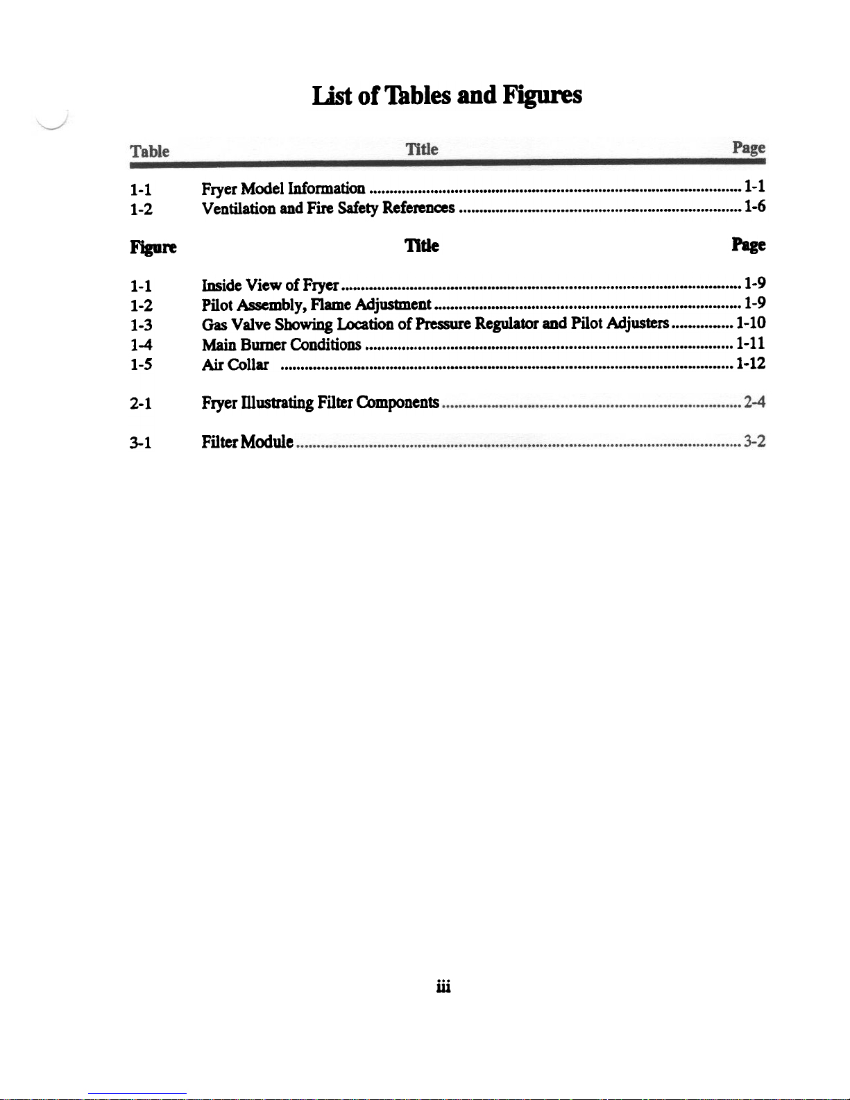
List of Tables and Figures
1-1
1-2
Figure
1-1
1-2
1-3
1-4
1-5
2-1
3-1
Fryer Model Information 1-1
Ventilation and Fire Safety References 1-6
Title
Page
Inside View of Fryer 1-9
Pilot Assembly, Flame Adjustment 1-9
Gas VaJve Showing Location of Pressure Regulator and Pilot Adjusters 1-10
Main Burner Conditions 1-11
Air Collar 1-12
Fryer mustrating Filter Components
FilterModule
iii
Page 10

iv
Page 11
Chapter 1: General Information and Installation
The frying system you have selected for your establishment is the Pita> Frialator Model SF14 UFM
series. This model oombines the oonvenience of built-in filtration and the compactness of under fryer
filtration into one easy to use unit. This fryer will give you many years of reliable service if you follow
the simple operation and maintenance procedures in this manual. Contained in this manual are the
general installation, operation, and maintenance procedures for the SF14UFM and SFI4RUFM.
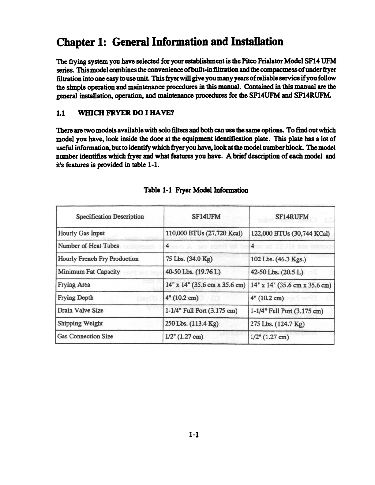
1.1 WHICH FRYER DO I HAVE?
There are two models available with solo filters and both can use the same options. To find out which
model you have, look inside the door at the equipment identification plate. This plate has a lot of
useful information, but to identify which fryer you have, look at the model number block. The model
number identifies which fryer and what features you have. A brief description of each model and
it's features is provided in table 1-1.
Table 1-1 Fryer Model Information
1-1
Page 12
1.2 CHECKING YOUR NEW FRYER
Your new fryer and it's filter have been carefully packed into one crate. Every effort bas been made
to ensure that your fryer will be delivered to you in perfect condition. As you unpack your new fryer,
inspect each of the pieces for damage. If something is damaged, DO NOT sign the bill of lading.
Contact the shipper immediately, the shipper is only responsible for 15 days after delivery. Check
the packing list enclosed with your fryer to ensure that you have received all of the parts to the fryer.
If you are missing any parts, contact the dealer from whom the fryer was purchased. As you unpack
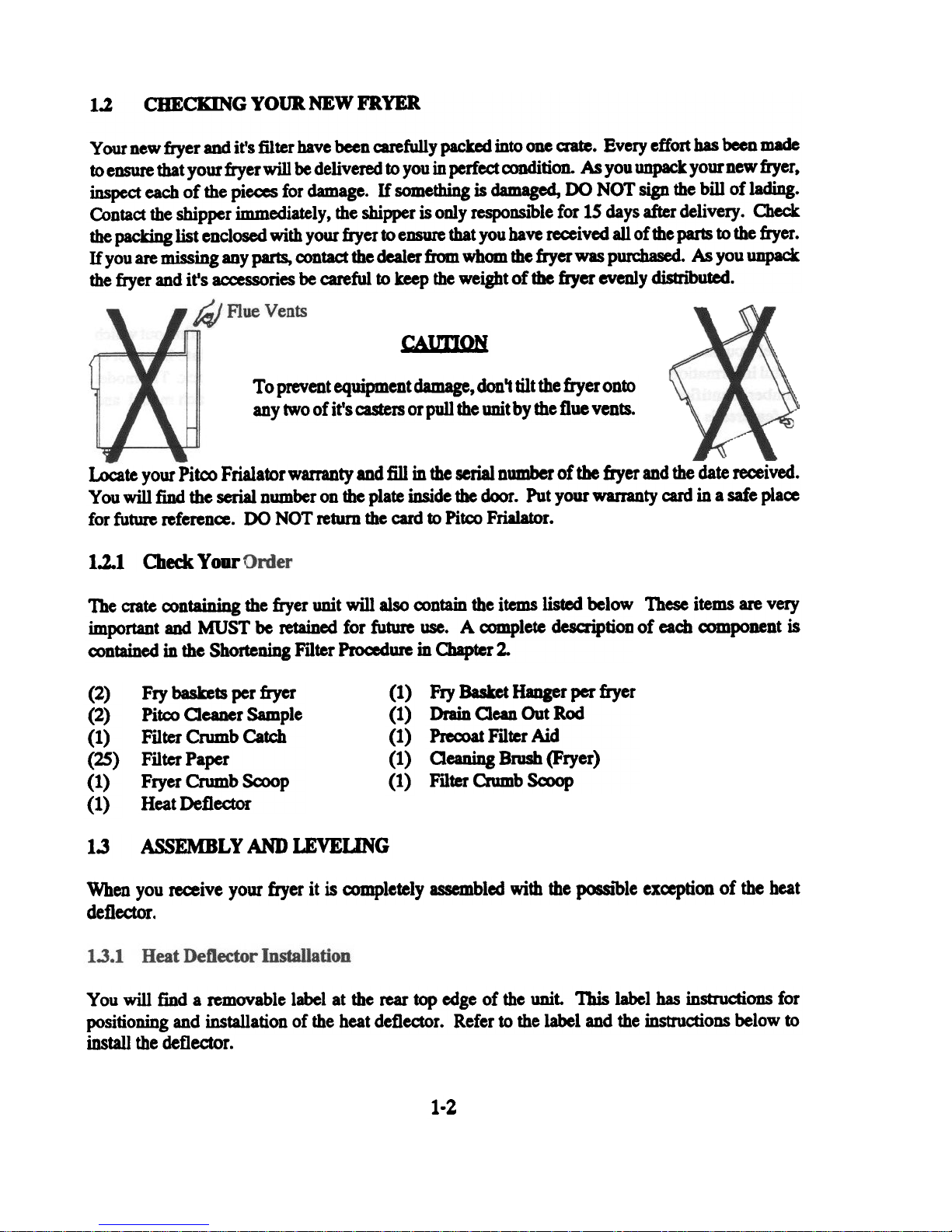
the fryer and it's accessories be careful to keep the weight of the fryer evenly distnbuted.
CAunON
To prevent equipment damage, don't tilt the fryer onto
any two of it's casters or pull the unit by the flue vents.
Locate your Pitco Frialator warranty and fill in the serial number of the fryer and the date received.
Y 00 will fmd the serial number on the plate inside the door. Put your warranty card in a safe place
for future referen~. DO NOT return the card to Pitco Frialator.
1.2.1 Check Your.
The crate containing the fryer unit will also contain the items listed below
important and MUST be retained for future use. A complete description
These items are very
of each oomponent is
contained in the Shortening Filter Procedure in Chapter 2.
(2)
(2)
(1)
~)
(1)
(1)
Fry baskets per fryer
Pitco Oeaner Sample
Filter Crumb Catch
Filter Paper
Fryer Crumb Scoop
Heat Deflector
Fry Basket Hanger per fryer
(1)
Drain Oean Out Rod
(1)
Precoat Filter Aid
(1)
Oeaning Brush (Fryer)
(1)
Filter Crumb Sa>op
(1)
1.3 ASSEMBLY AND LEVEUNG
When you receive your fryer it is completely assembled with the possible ex~ptioD of the heat
deflector.
You will find a removable label at the rear top edge of the unit. This label has instructions for
positioning and installation of the heat deflector. Refer to the label and the instructions below to
install the deflector.
1-2
Page 13
a. Remove the two self-drilling saews from the top, back area of the cooker.
b. Position the heat deflector so that the angled portion of the deflector is facing toward the
front of the fryer. Secure the heat deflector to the back of the unit using the sheet metal
saews previously removed.
~:=I
DO NOT obstruct the flow of combustioD/ventilation or air openings around
the fryer. Adequate cl~ around the fryer is necessary for servicing and
proper burner operation. Ensure that you meet the minimum clearances
specified in the installation instructions.
When properly installed the angled section of the heat deflector will extend over the flue
Co
opening to redirect the heal It SHOUlD NOT rover the flue opening. Nothing should
block the flue opening as this will cause the fryer to overheat and produce dangerous
gases.
1.3.2. Leveling
Using an appropriate wrench and level ensure that the unit is level.
a. Place the level across the front of the tank and rotate the adjustment on the front legs to
level the unit.
b. Perform step a to level the unit front to back by placing the level along the side of the tank.
1.4 INsrAL1.ATION
Although it is poSSIble for you to install and set up your new fryer, it is STRONGLY recommended
that you have it done by qualified professionals. The professionals that install your new fryer will
know the local building codes and ensure that your installation is safe.
~==I
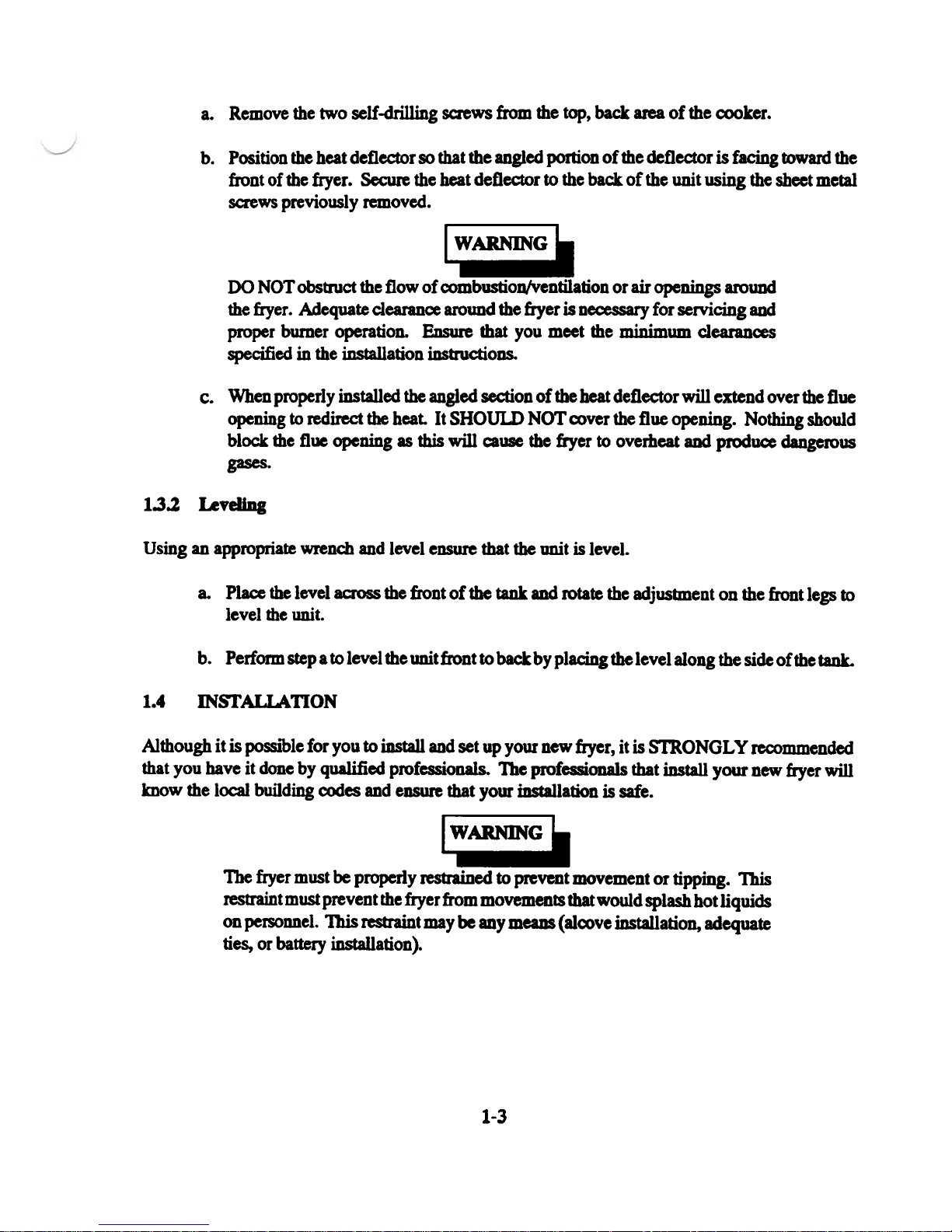
The fryer must be properly restrained to prevent movement or tipping. This
restraint must prevent the fryer from movements that would splash hot liquids
on personnel. This restraint may be any means (alcove installation, adequate
ties, or battery installation).
1-3
Page 14

Combustible
Construction
Back
Sides
In addition to the clearances required for proper fryer operation, there must be at least 23 inches of
Your fryer will give you peak performance when the gas supply line is of sufficient size to provide
the correct gas flow. The gas line must be installed to meet the local building codes or National Fuel
Gas Code (NFPA 54-1984) and ANSI Z223.1-1988 Latest Edition. In Canada, install the fryer in
aax>rdance with CAN/CGA-B149.1 or .2 and local codes. Gas line sizing requirements can be
determined by your local gas company by referring to National Fuel Gas Code, Appendix c, Table
C-4 (natural gas) and Table C-16 (propane). The gas line needs to be large enough to supply the
necessary amount of fuel to all appliances without losing pressure to any appliance. Other factors
that are used to determine the piping requirements are BTU requirements of the appliances being
oonnected and the length of pipe between the meter (main shut oft) and the appliances.
6"
6"-
N/A
Non-Combustible
Construction
6"
6"
N/A
1.4.2.1
which the
door.
[:::1
NEVER supply the fryer with a gas that is Dot indicated on the data plate.
Using the inoorrect gas type will cause improper operation. If you need to
Fuel ~s
appliance is
- Each fryer is equipped to work with one type of fuel. The type of fuel with
intended to operate is stamped on the data plate attadled to the inside of the
DO NOT use an open
1-4
for gas leaks!
Page 15

1.4.2.2 Gas Line Connection - Connect the fryer to the gas supply line with a oonnector that
amplies with the Standard for Connectors for Movable Gas Appliances (ANSI Z21.69-1987). If you
are installing a fryer with casters use a quick disoonnect refer to the Quick Disconnect installation
instruction, 1.4.2.3. Connect the gas line to the fryer using a pipe joint sealant that is resistant to
liquefied petroleum. If the fryer was disoonnected during the fuel line testing, use a solution of soap
and water to leak test the new oonnection.
NEVER use an adaptor to make a smaller gas supply line fit the
connedion. This may not allow proper gas flow for optimum
operation, resulting in poor cooker performan~..
1.4.2.3 OuickDjsa)nnectGasConnection-Gasfryers
equipped with casters must be installed with connedors
that comply with the Standud for Connectors for Movable
Gas Appliances, ANSI 221.69-1987, and Addenda
Z21.69A-1989. This connection should include a quick
disconned device that complies with the Standard for
Quick Disamnect Devi~ for Use With Gas Fuel, ANSI
Z21.41-1989. When installing a quick disoonnect you
must also install a means for limiting the movement of the
fryer. This device will prevent the gas line or the quick
disronnect from being strained. The restraining device
should be attached to the cooker on the back panel as
shown in the illustration. The quick disconnect, hose, and
restraining device can be obtained from your dealer.
1.4.2.4 Fuel SYR~IX Line Leak and Pressure Testine - The fuel supply system must be tested
before the fryer is used. If the fuel line is going to be tested at a pressure greater than (»1/2 PSIG
(3.45 kPa), make sure that the fryer is disamneded from the fuel line. If the fuel line is to be tested
at a pressure equal to or less than (s) 1/2 PSIG (3.45 kPa), the fryer can be COft-!!e-m.rl but the unit's
gas valve must be shut. Test all gas line connections for leaks with a solution of soap and water when
pressure is applied.
1.4.3 Electrical Connection
The electrical servi~ used by the fryer must oomply with local cx>des. If there are no local a>des that
apply, refer to the National Electrical Code (NEC) to install the servi~. In Canada refer to CSA
Standard C22.1 and local codes. Wiring diagrams are provided inside the fryer door. The power
requirements for the fryer are shown below.
Input Voltage
Current per fryer
NonCE
cooker
burner
120 V Ac, 60Hz
7 Amps
220 (or 240) V Ac, SOliz
3 .s Amps
1-5
Page 16

~=:I
The fryer is equipped with an oil proof, three prong (grounding) plug for your
protection against electrical shock hazard in the event of equipment malfunction. DO NOT cut or remove the grounding (third) prong from this plug. This
plug must be plugged into a properly grounded three prong receptacle.
The fryer has one power supply for the fryer controls and the filter module. The fryer must be
grounded in accordance with local code; if there is not a local code, comply with NBC ANSI/NFP A
No. 70-1990. The fryer should be plugged into a receptacle at all times to keep power supplied to
the filter line heat tape.
1.4.4 VentilatioD and Fire Safety Systems
Your new fryer must have proper ventilation to function safely and properly. Exhaust gas
temperatures can reach as high as 1200°F. Therefore, it is very important to install a fire safety
system. Your ventilation system should be designed to allow for easy cleaning. Frequent cleaning
of the ventilation system and the fryer will reduce the chan~ of fire. Table 1-2 provides a list of
referen~ documents that provide guidance on ventilation and fire safety systems. This table is not
necessarily complete. Additional information can be obtained from the American Gas Association,
8501 East Pleasant Valley Road, Ceveland, OH 44131.
Table 1-2. Ventilation and Fire Safety Referen~s
1-6
Page 17

Excessive ventilation causes drafts, which will interfere with the proper operation of the pilot and
the burner. Leave at least 18 inches of open space between the fryer's flue vent opening and the intake
of the exhaust hood.
CAU'I10N
Ensure that your ventilation system does not cause a down draft at the fryer's
flue opening. Down drafts will not allow the fryer to exhaust properly and will
cause overheating which may cause permanent damage. Damage caused by
down drafts will not be covered under equipment warranty. NEVER allow
anything to obstrud the flow of combustibles or ventilation exiting from the
fryer flue. DO NOT put anything on top of the flue area.
NonCE
NEVER connect the blower directly to the flue openings. The direct flow of
air will cause poor temperature recovery, poor ignition, inefficient operation
of the fryer, and could extinguish the pilot.
1.5 INI11AL ADJUSTMENTS
After your fryer has been installed as described in section 1.4, it needs to be adjusted to ensure that
it will perform as designed. These adjustments must be performed by a qualified person. To
perform these adjustment the following tools will be needed:
. Manometer (low pressure gauge) . Digital Thermometer (Temperature probe)
. DC Millivolt Meter
1.5.1 Visual Checks
Before you begin filling and adjusting the fryer, perform the following visual
checks:
After the fryer is in its permanent location, check for levelness. Any
a.
additional leveling that is necessary can be perfonned as described
in section 1.3.
b. Oleck the temperature bulbs (thennostat/high-limit), located in the
fryer tank to ensure that the mounting screws are tight The figure
shows the probe typical location. Look down inside the fryer tanks
to see the probes. 8,. Nt 1_.
Ensure tIIIt Un. pen-
1-7
Page 18

CAtmON
Before going any further, fill the fryer with WATER. Water is used for the
installation adjustments because the temperature will never exceed 212°F
(100°C) thereby allowing plenty of adjustment time. Never let the water level
go below the OIL LEVEL mark on the rear of the tank.
G;:a
There is an open Bame inside the fryer. The unit may get hot enough to set
near by materials on fire. Keep the area around the fryer free from
1.5.2.1 Li~htin& Instroctions for Manual Pilot l1ihts - To light the pilot light refer to these
instructions and Figure 1-1. The numbers in parenthesis refer to Figure 1-1 callouts.
G:::I
Wait 5 minutes before attempting to relight the pilot to allow for any gas in
the fryer to dissipate.
a. Open the gas supply valves to the fryer.
b. Open the fryer's door to gain access to the controls. Turn the thermostat control knob
counterclockwise to the off position.
Turn the Unitrol gas valve knob (tan knob) (2) to the Pll..OT position and
c.
push in on the knob. Hold the knob in for approximately one minute to
purge the air out of the line. Hold a flame to the pilot light until the pilot
(3) ignites. This may tate a little while the first time you light the fryer
because of air in the lines. Once lit, hold the knob in for approximately
60 seconds and then release.
d. If die pilot goes out wait 5 minutes and repeat step c. If after three tries the pilot will not
remain lit, refer to the operator troubleshooting section of this manual.
e. Turn the Unitrol gas valve knob (tan knob) counterclockwise to the ON
position.
f. Set the thermostat control knob to the desired temperature setting.
(lJ0 ~
~ ~
~~
(1)
1.8
Page 19

g. The main burner (4) will light and be controlled by the thermostat. The pilot burner will
remain lit regardless of the switch position.
1.5.2.1.1 Pilot Flame Adiustment - The pilot flame should be adjusted to prod~ the ~r
millivolt output from the pilot sensing devi~. Millivolt output for the thermopile should be between
300 and 500 millivolts. Figure 1-2 shows the pilot assembly with examples of the incorrect and
correct pilot size. Example A illustrates a pilot flame size that is too small to produ~ sufficient
millivolt output. Example B is the correct size for proper millivolt output
TME~ll£ \
PILOT IUDU \ \
M
B
A
Figure 1-2 Pilot Assembly,
1-9
Page 20

a. This test requires a DC millivolt meter set to a scale of O-l(XK)mv.
b. Locate the thermopile wires coming from the thermostat!High Limit box going to the gas
shut off valve. The wire insulation size decreases near the gas valve connections.
Connect the negative (-) test probe to pilot bracket.
Co
Connect the positive (+) test probe to one of the High Limit terminal
d.
Remove the pilot flame adjustment cover.
e.
PRESSURE REGULATOR
(UNDER CAP SCREW)
PILOT ADJUSTER LOCATION
(UNDER CAP SCREW)
LOCATION
g. Rotate the screw in the direction to achieve a reading of 400 rlO mv for thermopiles.
h. Replace the pilot flame adjusting screw cover.
NonCE
1-10
Page 21

For the burners to work the gas supply valve must be open and the main power switch must be on.
The main burner receives gas from the main gas supply through the thermostatically oontrolled valve.
When the therDlostat is turned up the gas control valve opens and the pilot will ignite the burners.
After the burner system is operating, perfOrDl the burner adjustments in the following procedure.
Figure 1-5 illustrates the different oonditions possible for the main burner.
incoming gas pressure.
Adjust manifold pressure as
described in 1.53.2.
INsumCIENT GAS PRESSURE
The flame
-liftofr
The flame seems to wli:
the faa; of the burner.
To correct adjust
burner as describc
1.5.3.2.
adjust main
described in
EX~IVE FLOW
Figure 1-4 Main Burner Conditions
1-11
Page 22

1.5.3.1 Gas Une Rgrements - A properly installed gas supply system will deliver 7.0 %2.0.
W.Co natural gas (12.0 %2.0. W.c. LP) to all appliances oonnected to the line, operating at full demand.
1.5.3.2 Burner Adjustment -The burners must be
burner flame using the following procedure.
a. Ensure that the gas oontrol valve is in the OFF position. Remove the manifold pressure
tap plug and connect an accurate pressure gauge (range of 0-16" w.c. in 0.1" increments)
or manometer.
b. light the pilot burner (~ 1.5.2) for the unit being tested and adjust the thermostat to light
the main burners.
c. The installed presswe gauge reading should be tbesame, ~.1., as that marked OD the data
plate inside the door. If the pressure is correct go to step e, if DOt, adjust the pressure.
d. To adjust the pressure, remove tberegu1atoradjustmentsaewcover(~ Figure 1-3). Use
a flat tip screwdriver to adjust the screw until the proper pressure is reached. Turning the
~w clockwise will inaease the pressure, counterclockwise will deaease the pressure.
f.
To remove the pressure gauge, turn gas control valve to OFF. Remove the gauge and
install the pressure tap plug.
Adjust the
BURNER
ORIFICE
I"""""'~~
SET SCREW
BURNER FI1TING
GAS PRESSURE 1
TEST PLUG
Figure 1-5 Air
Collar
1-12
Page 23

Now that the pressure is set for proper operation, set the main burner flame. Unlock the
g.
air collars by loosening the set screw for the collars. Turn the gas control valve to ON
and turn thermostat to light the main burners.
h. Adjust the shape and size by raising
with well defined inner cones.
provided.
1.5.4 INITIAL CLEANING
When the fryer is shipped, many of its parts are covered with a thin coat of oil for protection. Before
the fryer is ready for cooking it must be cleaned. This will remove the oil coating and any foreign
matter that may have !.~JII!ulated during storage and shipment. Perform the cleaning as described
below.
a. Fill the tank with water and add one packet of Pita> fryer cleaner or a mild detergent.
b. Turn the fryer on and set the thermostat to 200~. Allow the fryer to heat for 15 minutes.
NonCE
Do not leave the fryer unattended during cleaning. Never let the water level
go below the "OIL LEVEL" mark on the back of the tank.
Using the fryer cleaning brush, scrub the inside of the fryer to remove protective coating.
c.
When cleaning is complete, turn off the fryer main burners and turn gas valve knob to the
d.
PILOT position. If the fryer has electronic ignition turn the gas control valve to the OFF
position. Drain the water into a container suitable for hot water and dispose of it.
When the tank has oooled, rinse it thoroughly with 0001 water. Continue to rinse the tank
e.
until the cleaner has been rinsed, thoroughly from the tank.
,
Using a clean dry cloth, wipe out all of the water. Be very thorough removing the water,
f.
because any residual water will cause hot oil to splatter out of the fryer.
CAImaN
Mild steel tanks must be wiped down/coated with oil to keep the tank from
rusting.
Now that the tank is clean, you are ready to fill and operate the fryer. Refer to 2.1 for
g.
instructions on adding shortening to the fryer.
1-13
Page 24

loSoS
Thermostat Calibration Check
NOnCE
Thermostat calibration requires that the temperature of the fryer be raised
above boiling. Therefore, you will need to drain the water from the fryer and
fill it with oil. Before removing the water, perform the initial cleaning of the
fryer. Oeaning the fryer now will prevent you from having to drain the oil and
refill with water later.
Filling the
fryer with oil is described in 2.1. To perform the calibration check detailed below you will
need a digital thermometer.
b. Set the thermostat at 325°F and wait for the temperature reading on the thermometer to
rise. As the temperature rises toward 325°F watch the thermometer closely.
c. If the shortening temperature reaches 350oP and the burners DO NOT turn off, turn the
thermostat down. Keep lowering the thermostat setting until the burners go out.
(X)uld be defective.
d. Let the fryer cycle 4 to 6 times before checking the temperature. Compare the
thermometer temperature against the thermostat setting. If the values are more than 5°F
apart, calibrate the thermostat using the appropriate calibration procedure in this manual.
CAtmON
Contact your ASAP representative.
1.5.6 1bennostat Calibration
To calibrate the thermostat the dial must be removed from the shaft. The adjustment for the
thermostat is inside the dial shaft.
Place the
a.
sensors.
b. Set the Thermostat to 325Of and wait for the
rise.
Let the fryer cycle 4 to 6 times to ensure that the temperature has stabilized.c.
5°F apart, calibrate the thermostat using
1-14
temperature reading on the thermometer to
Compare
If the values are more than
the
procedure.
Page 25

d. Set the thermostat dial to 32S°F.
e. Remove the thermometer dial by pulling the knob straight out. DO NOT rotate the dial.
f. Hold the outside of the shaft so it does not move. Use the tip of a small, flat tip screw driver
to scrape away the sealing compound from the adjustment screw.
g. Turn the adjustment screw clockwise to lower the temperature setting and counterclock-
wise to raise the temperature. One quarter turn changes the temperature approximately
25°F.
Turn the adjustment until the burners turn on at 32S°F. Repla~ the knob and allow the
h.
fryer to cycle 4 to 6 times. Check the temperature of the thermometer against the
thermostat dial, if it is greater than 5°F differen~ repeat the calibration procedure.
i. When the calibration is correct, remove the thermometer and rep1aC% the tube saeen.
1.5.7
HIgh Umit Test
TIllS TEST SHOULD BE PERFORMED BY OUAUFIED PER.~ONNEL ONLY
1-1'
Page 26

1-16
Page 27

Chapter
This chapter describes how to operate your fryer to obtain the best performance. Included in this
chapter are filling, operating, and cleaning instructions for gas fryers.
2.1 FIUJNG THE FRYER
Both liquid and solid shortening can be used in the fryer. If solid shortening is used, it is
recommended that you use the melt cycle feature (optional) to melt the shortening. You can melt solid
shortening without the melt option, but you must carefully follow the instruction in section 2.2.2.
2:
2.1.1
2.1.2 FllllDg the Fryer With SoUd Shortening
FUling the Fryer With liquid Shortening
a. Make sure the drain valve is completely closed.
b. Fill the fryer with oil to the "Oil Level" line marked on
the back of the tank.
.. -.
~==I
Never melt blocks of solid shortening on top of the burner
tubes. This will cause a fire, and will void your warranty.
Pa.
a.
Make sure the drain valve is completely closed.
b. Remove the screen oovering the tubes.
c. Cut the shortening into cubes DO larger than I". AL-
WAYS pack the shortening below, between, and on top
of the burner tubes. DO NOT leave any large air gaps.
Use care when packing the solid shortening in the tank.
DO NOT bend or break the temperature sensor probes.
If these are damaged the fryer will not function properly.
d. Once the fryer is packed with shortening, the shortening must be melted.
shortening refer to the Fryer Start-Up section for your fryer
~
To melt the
2-1
Page 28

2.2 MEL11NG SOLID SHORTENING
NonCE
The melting procedure below requires the manual cycling of the fryer. Watch
carefully for smoke. If smoke is noticed, die shortening is scorching. To
prevent this, decrease the time you leave the burners on.
a. Rotate the thennostat to cause the main burners to light and remain lit for 4 seconds.
Rotate the thermostat back to off for 30 seconds.
b.
Continue cycling the main burners until most of the solid shortening is liquefied and the
c.
temperature reaches 150°F. At 150°F leave the thermostat set at the desired temperature.
The burners will remain on constantly until the shortening temperature reaches the
thermostat setting.
d. On~ at temperature, the fryer is now operating normally and ready to use.
2.3 OPERATING IN~UCl10NS
To ensure the food always comes out the very best, follow the preparation insttuctions for the food
you are cooking. Using the best shortening makes the best fried foods. The best shortening will last
longer than lower grade shortening and save you money. When not in use the shortening should be
cooled and covered to prevent contamination.
CAU110N
The fryer has been installed using restraining devices to prevent accidental
tipping or movement. Do not attempt to move the fryer when it has hot 1
in it. Splashing hot liquids can cause severe bums.
[==~
Water and shortening DO NOT mix. Keep liquids away from hot shortening.
Dropping liquid frozen food into the hot shortening will cause violent boiling.
2.3.1 Fryer Start-Up
DO NOT sf ART FRYER Wn'HOtn' FILUNG WITH OW
a. Ught the pilot light as described in section 1.5.2.
2-2
Page 29

knob is located behind the front doors or on the front oontrol panel.
c. The main burners will light and cycle at the thennostat setting.
2.3.2 Fryer Shut-Down
There are two shutdown modes of fryer operation, STAND BY and COMPLETE. The standby mode
removes the ability for the fryer's main burners to cycle. Complete shutdown turns off the gas supply
to the fryer. Shut down the fryer by:
STANDBY Turn the thennostat to OFF. Depress and turn the gas valve clockwise
to the PILOT position (if fryer has an electronic ignition turn the gas
valve to the Off position). The fryer is now in Standby and can remain
this way for only brief periods of time. NEVER leave the cooker in
standby overnight.
COMPlEI'E To oompletely shut down the cooker, turn the gas valve counterclock-
wise to the OFF position and turn the power switch off (if used). The
fryer is now completely shut down and can be cleaned and filtered.
~
~
2.3.3 Power Failure
0
If power is removed from the fryer during filtering, place the filter switch in the OFF position and
close the return valve. When power is restored restart the filter procedure
'--I
2-3
Page 30

2.4 SHORTENING FILTER PROCEDURES
This section describes the procedures used to filter fryers using the solo filter unit. Figure 2-1 shows
the locations of the components used in the filterproc:ess. The filter accessories and tools you should
have to perform normal filtering operations are described on page 2-5. Frequent filtering of your
shortening will prolong the shortening's usable life. Daily shortening filtering is strongly
recommended .
Return
Valve
Drain Valve
Handle
Hush Hose
Valve
optional)
NOTE
See Maintenance Section for Filter
Operational Information.
CLOSEDVALVE
(Handle Across Body)
Figure 2-1 Fryer mustrating Filter Components
Valve Handle
Valve Body
VALVE OPEN
(Handle Inllne With Body)
2-4
Page 31

Return Valve
pump on, allows the shortening to return to the design, this sooop is used to remove the debris
fryer tank. from the filter pan.
Drain Valve BLACK - Drain the oil from the Cleaner - Used during fryer boil-out cleaning.
fryer tanks to the filter pan.
oil from the filter unit to the fryer. Simply push
to left OD fitting to connect. Pull to right to
disa>nnect.
Filter Unit Cord - Provides electrical power to
the illter unit.
FUter
Paper
Package
of pre-cut filter
Preooat FUter AId . Coarse Diatomaceous earth
used to enhance the filter ability of the filter
media.
Cleaning Bnlsh -This long handled stiff bristle
brush is used to brush down the crumbs inside the
fryer tank during shortening filtering.
FIlter Crumb Catch - Mounts in d1e filter pan lid
and catches large debris during filtering.
flush Hose (OPl10NAL) - Attached to the
filter piping, this hose and nozzle is used to flush
out the fryer tank. This hose is an optional item.
~;=I
At operating temperature the shortening temperature may be greater than
300°F. Extreme care should be used when filtering operating temperature
shortening to avoid personal injury
2.4.1 General FDter Hints
Ensure that all oil in the filter pan is returned
important if you are using solid shortening.
FryerCmmb Scoop -Aspecia11y designed long
handle scoop for scooping out the fryer. The
scoop section is narrow enough to fit down between the fryer burner tubes.
This is very
Always use Pitco Precoad for fastest filtrations, maximum labor saving, and cleanest/
clearest shortening possible. Impaired filter performance will result without the use of
a filter aid.
The longevity of your oil is related to how clean you keep it. With a Pitco solo filter
system, it is easy to do a quick drain/refill anytime. By removing suspended particles
often, it prevents them from burning.
2-5
Page 32

4. When the time it takes to refill the fryer after filtering exceeds 3:00 minutes, scrape the
filter bag or paper. If scraping does not bring the refill time back down change the fi1ter
paper as described in 3.1.
S. The mter pump is protected from dogging by a special screen in the pickup tube.
Cean this screen each time a new mter is installed (see Chapter 3, 3.4.2)
6. If you have filter system problems refer to section 3.4.2.
7. Purge the filter lines by allowing the filter pump to run lS seconds after air bubbles are
seen inside the fryer tank.
2.4.2 Filter Procedures: Numbers in parenthesis refer to Figures 2-1 and 2-2.
NonCE
.
When working with hot oil ALWAYS wear oil-proof, insulated gloves.
NEVER
.
Run the filter system without a filter bagtpaper.
.
Attempt to filter more than one fryer tank at a time.
.
Empty the oil from the fryer before turning OFF the fryer burners.
.
Store the UFM Filter Unit anywhere other than in the fryer filter cavity.
Disconnect die filter pan, slide it out and empty the crumb basket. Scrape previously
a.
filtered residue off the filter paper. Examine the filter bag for dark, scuffed, or tom areas.
Refer to 3.1.1 for filter bag replacement instructions. Re-install the pan.
Turn die fryer OFF (See Standby Shutdown, section 2.3.2). Remove the baskets from the
b.
fryer tank( s). Use the clean out rod to lift out die tube screens. If there are excess aumbs
in the fryer tank, remove them with the crumb scoop.
If you have replaced or scraped the filter paper, stir in Preooat
Co
Filter Aid to the shortening in fryer (8 oz. by volume). After
cleaning out the excess debris with the fryer sooop sprinkle the
powder into the first fryer to be filtered and stir the powder into
the oil.
NonCE
Always open a
valve before starting the filter pump.
2-6
Page 33

Slowly open the drain valve by using the black knobbed extension rod. If necessary use
d.
the clean-out rod to clear the crumbs from the drain. Use the long handled brush to clean
the sides of the tank as the oil drains.
Open the red handled return valve to the tank you are filtering. When the tank is empty
e.
close the drain valve and turn on the filter pump. As the tank fills, brush the inside of the
tank to remove crumbs.
f. When bubbles are seen coming out of the oil return spout, turn off the pump. Open the
drain valve and allow the tank to drain again. Repeat steps b through d until the tank is
clean.
When cleaning is oomplete turn the pump off, close the drain valve, and repla~ the tube
g.
screen. Open the red handled return valve and turn on the pump to refill the fryer with
the filtered oil. Continue to run the filter pump until bubbles oome out the oil return
opening. Turn the pump off and close the red handled return valve. If necessary add more
shortening to the tank to return the shortening level to the fill mark. The fryer is now ready
for use.
2.5 DAILY CLEANING
Your fryer should be cleaned every day to maintain peak performance and appearan~. Perform the
procedures below every day,
a. Wipe up any shortening that spills onto the exterior of the fryer. This should be done with
a clean soft cloth.
b. Use WamI water with a mild detergent to clean surfaces. Be careful not to get water in
the shortening. Rinse
Co Use.
completely and dry thoroughly before use.
stains ifscouring powder or pad to dean
d. Perform the weekly boil out cleaning of your fryer deSCrIbed in section 3.2.
2.7
Page 34

2-8
Page 35

Chapter 3: Owner Maintenance and
This chapter provides you with the information and procedures necessary to perform basic fryer
mainteDan~ and adjustments. If after performing maintenan~ on your fryer it does not perform
properly, contact your
Adjustments
[==-
disconnected before
The power supply
appliance.
3.1 ~TER MEDIA REPLACEMENT
This section the filter system's components and
media.
be
the procedures necessary to replace the filter
~=:I
At operating temperature, the shortening in the fryer may be hotter than 375Of
(190°C). This hot, melted shortening will cause severe bums. Do not let the
hot shortening touch your skin or clothing. Always wear insulated oil-proof
gloves when working on the filter system.
The filter module stores neatly under die fryer. The unit is very easy to use and allows for quick
installation and filtration, even under die busiest conditions. The filter module is shown in Figure
3-1 widl specific components and features pointed out and briefly described.
Follow the procedures below to
the fIlter
or cleaning the
It will be easier and safer if the filter assembly has cooled to room temperature
before handling any filter parts.
a. To remove the filter pan, disconnect the filter tube oonnection. This is done by sliding
the insulated portion of the connector out of the receiving portion of the oonnector.
b. Graspthe
pan lid.
Remove the aumb catch tray from the top of the filter pan. Discard any debris that may
be in the crumb catch.
filter pan and
~=:I
gently pull the assembly out the front of the fryer, remove the flIter
3-1
Page 36

(1) Fdter Pan - Holds the oil from the fry tank.
(2) Pick-Up Tube - ConnedS filter envelope
assembly to piping. Inoorporates a strainer to
protect filter pump from grit in the event of
envelope failure.
(3) FOter Assembly CoDDector - An insulated
handle covers the filter pan assembl y connection.
This connection separates the filter pick-up as-
sembly from the filter piping for removing the
filter pan for cleaning.
(4) FOter Media Connector -Connects the filter
pick-up tube to the filter media rack. An internal
screen keeps debris out of the filter pump.
c: @
,
Figure 3-1 Filter Module
(5) Flexible Coupling. Flexible coupling allows
for easy movement when connecting and discon-
necting the pickup tube from the fryer.
(6) Casters . Allows for easy movement of the
pan.
3-2
Page 37

Lift up on the filter paper assembly and remove from the filter pan. Unscrew the suction
d.
tube from the filter paper support rack. Remove the clip screen and slide the filter paper
support rack assembly out of the filter bag.
e. All of the filter pick up assembly
parts can be washed in a dish washer
~ or a pot sink. Hush out the suction
0 tube assembly with hot water. The
pick up tube screen keeps grit and
solid material from binding the pump.
After flushing the pick up tube screen
check to ensure that the screen is free
of debris. After cleaning, it is very
important to thoroughly dry the parts
before re-assembling. Water and oil
000 do not mix. Water in hot oil will
cause the oil to splatter.
Start fe-assembling the filter pick up
f.
assembly by sliding the new filter
paper on to the filter paper support
rack. Ensure that the hole in the filter
paper goes over the pick up tube assembly threaded connector.
Pick
aip
(Designed
low scraping
sediment with out
tearing paper)
Tube
Conn
~
'Filter Paper
Support Rack
Fold the open end of the bag in two folds. The fIrSt
g.
fold should be approximately 1 inch from the end
and the second should be over the edge of the rack
assembly.
Slide the clip screen over the folded end of the filter
h.
paper. Ensure the opening of the clip screen goes
over the pick up tube connection. Screw the
suction tube assembly onto the threaded connection.
i. Place the filter rack assembly in the filter pan and install the aumb catch tray in the top
of the filter pan lid.
Place lid on filter pan.
j. Slide the illter pan assembly back into the fryer and attach the pick up tube connector to
the filter unit connection.
3-3
Page 38

3.2 WEEKLY FRYER CLEANING (BOIL OUT)
The fryer should be thoroughly cleaned once a week. This cleaning should include a complete
draining of the fryer and a boil out. This would also be a good tinle to replace the filter paper if
necessary .
a. You will need a container large enough to hold the volume of the tank. This container
should also be able to withstand boiling water temperatures.
CAU110N
Completely shut down the fryer when the oil is to be replaced by water, and
when the heating portion of the cleaning is complete. This will prevent the
heating system from coming on during the oil draining and water filling
procedure.
Drain the oil from the fryer and discard or save for reuse. Remove tube rack/mesh tube
b.
screens and remove any large debris from the bottom of the fry tank. Once clean, return
tube rack/mesh screens to the fry tank. Cose the drain valve and fill the fry tank with
water and noncaustic detergent. For best results use Pita> Fryer Cleaner.
Restart your fryer as described in 2.3 and set the thermostat
c.
to a slow boil. DO NOT allow water to boil because excessive J
the water is at a slow boil turn off the fryer.
Allow the fryer to soak for 20 minutes to soften shortening deposits and carbon. Use fryer
d.
brush to remove any residue from tank, beating tubes, and side walls. Perform the daily
cleaning procedure described in section 2.5.
e. Remove the filter unit from under the fryer. Slide a container to catch the water under the
fryer so that the pipe that is nonnally aimed
and open the drain valve.
f. Drain the hot water to the oontainer and rinse the tank with clean warm water.
g. Wipe
the tank dry with clean cloth wipes. Close the drain valve and remove
h. Refer to section 2.1 to refill the fryer.
3.3 FLUE INSPECI'lON
to 200°F and bring the water
will occur. Once
into the filter pan is aimed into the container
the large
It is recommended that once every six months, with the cooker cooled down, you examine the flue
area. Check for corrosion or blockage of the flue. Ensure that the cooker is shutdown and do not turn
it on during the examination. Examination of the flue area during cooking may cause bodily injury.
3-4
Page 39

3.4 TROUBLESBOO11NG
This section is provided to aid you in the event of fryer or filter troubles. If these troubleshooting
procedures do not correct your problem contact a qualified technician or the factory. The
troubleshooting procedures are in a flowchart format.
3.4.1 Fryer Troubleshooting
Refer to this section to correct common problems that may be encountered in equipment operation.
3-5
Page 40

3.4.2 Filter Troubleshooting
Refer to this section to correct common problems that may be encountered during filter operation.
3-6
Page 41

YES
~
~"~\I8Iv."'I.n~~ e ..~. ~..~~ t.-8~
~ "-8 ~ ~ .. ~ .. .. -1.JIDe' ~ ...
... .. ~ bI' - 8'8.
~ .. de8ed v8V8 ... ...
~~..~. ~..
"'_1d8d ~b*8~.~ --~~..
ra~~. ~..~.. -~
~ ~ «*aJI: ~.
..va ~.~~-,
tC)
~ .-u ~ ~ be
YES ~- ~ lie ~ dI8dWg8
*-. ~10~12~
b*8 ~ .. PI8I1»
MIdI ON.
Sold 8tut81~ ~ be
~ oW tie ~ di8dwge
YES b*8 mq 1118 ~ 8WId1
... ~10~12"""
ON. If tie .. hM been
,. ... - ~ tyer ..
".~...b'45
b8b8 ~.
)-7
Page 42

3-8
Page 43

v
~
.., I
 Loading...