

Page 1
IMPORTANT FOR FUTURE REFERENCE
Please complete this information and retain this manual
for the life of the equipment:
Model #: ___________________________
CRTE: Electric Counter Top Rethermalizer
Installation & Operation Manual
C
Serial #: ___________________________
Date Purchased: ____________________
U
R
L
U
ENGLISH
L20-259, Rev 7 (09/13)
Page 2

TO THE PURCHASER, OWNER AND STORE MANAGER
Please review these warnings prior to posting them in a prominent location for reference.
WARNING
DO NOT store or use gasoline or other flammable vapors and
liquids in the vicinity of this or any other appliance.
WARNING
Improper installation, alteration, service or maintenance can
cause property damage, injury or death. Read the
installation, operating and maintenance instructions
thoroughly before installing or servicing this appliance.
WARNING
Installation, maintenance and repairs should be performed
by a Pitco Authorized Service and Parts (ASAP) company
technician or other qualified personnel. Installation,
maintenance or repairs by an unauthorized and unqualified
personnel will void the warranty.
WARNING
Installation and all connections must be made according to
national and local regulations and codes in force.
WARNING
A country approved all pole circuit breaker wi th a minimum
open contact gap of 3mm must be used for proper
installation. (CE countries)
WARNING
During the warranty period if a customer elects to use a nonoriginal part or modifies an original part purchased from
Pitco and/or its Authorized Service and Parts (ASAP)
companies, this warranty will be void. In addition, Pitco and
its affiliates will not be liable for any claims, damages or
expenses incurred by the customer which arises directly or
indirectly, in whole or in part, due to the installation of any
modified part and/or received from an unauthor ized service
center.
WARNING
This appliance, when installed, must be electrically grounded
in accordance with local codes or national codes. For
domestic models, in the absence of local codes the
installation must conform to the National Electric Code,
ANSI/NFPA 70, or the Canadian Electrical Code, CSA C22.2,
as applicable.
WARNING
Adequate means must be provided to LIMIT the movement or
this appliance without depending on the electrical cord
connection. Single appliances equipped with legs must be
stabilized by installing anchor straps. All appliances
equipped with casters must be stabilized by installing
restraining chains.
WARNING
DO NOT alter or remove structural material on the appliance
to accommodate placement under a ventilation hood.
WARNING
This appliance is not intended for use by persons (including
children) with reduced physical, sensory or mental
capabilities, or lack of experience and knowledge, unless
given supervision or instruction concerning use of the
appliance by a person responsible for their safety.
WARNING
If the appliance is equipped with a power cord and it is
damaged, it must be replaced by a Pitco Authorized Service
and Parts (ASAP) company technician, or a similarly
qualified person in order to avoid a hazard.
The power supply must be disconnected before servicing,
maintaining or cleaning this appliance.
The appliance is NOT jet stream approved. DO NOT clean
the appliance with a water jet.
DO NOT attempt to move this appliance or transfer hot
liquids from one container to another when the unit is at
operating temperature or filled with hot liquids. Serious
personal injury could result if skin comes in contact with the
hot surfaces or liquids.
DO NOT sit or stand on this appliance. The appliance’s front
panel, tank, splash back, tank cover, workshelf, drain board
is not a step. Serious injury could result from slipping,
falling or contact with hot liquids.
NEVER use the appliance as a step for cleaning or accessing
the ventilation hood. Serious injury could result from slip s,
trips or from contacting hot liquids.
The water level should be maintained at the level line. DO
NOT turn the appliance on until the heating elements are fully
covered with water at all times. Serious injury could result
from hot steam vapors off the heating elements.
If overflow drain is not equipped or if overflow drain stop is
used, do not leave appliance unattended while filling with
water. Over filling the appliance can cause serious injuries
and damage the equipment.
Completely shut the appliance down when the water is being
drained from the appliance. This will prevent the appliance
from heating up during the draining and filling process.
Serious injury can occur.
This appliance is intended for indoor use only.
DO NOT operate appliance unless all panels and access
covers are attached correctly.
It is recommended that this appliance be inspected by a
qualified service technician for proper performance and
operation on a yearly basis.
WARNING
WARNING
WARNING
WARNING
WARNING
WARNING
WARNING
WARNING
WARNING
WARNING
WARNING
L20-259, rev. 7 (09/13) ii
Page 3

INSTALLATION
1. INSTALLATION ................................................................................... 2
1.1. CHECKING YOUR NEW APPLIANCE .......................................................................................... 2
1.2. INSTALLATION CLEARANCES ................................................................................................... 3
1.3. INSTALLATION TO COUNTER ..................................................................................................... 3
1.4. DRAINAGE CONNECTIONS ......................................................................................................... 3
1.5. ELECTRICAL CONNECTIONS ..................................................................................................... 4
1.6. VENTILATION AND FIRE SAFETY SYSTEMS ............................................................................. 6
1.7. INSPECTION .................................................................................................................................. 6
1.8. INITIAL CLEANING........................................................................................................................ 7
2. OPERATION ........................................................................................ 8
2.1. FILLING THE APPLIANCE ............................................................................................................ 8
2.1.1. FILLING THE COOKER TANK .................................................................................................................................... 8
2.2. APPLIANCE START UP ................................................................................................................ 8
2.2.1. High Temperature Limit Switch .................................................................................................................................... 8
2.2.2. Liquid Level Control Sensor ......................................................................................................................................... 8
2.3. COOKING ....................................................................................................................................... 9
2.3.1. ADDITIONAL CONTROLLER FUNCTIONS ................................................................................................................ 9
2.3.2. COOKING TIPS ........................................................................................................................................................... 9
2.4. APPLIANCE SHUTDOWN ............................................................................................................. 9
3. PREVENTATIVE MAINTENANCE .................................................... 10
3.1. DAILY PREVENTATIVE MAINTENANCE ................................................................................... 10
3.1.1. APPLIANCE INSPECTION ........................................................................................................................................ 10
3.1.2. CLEANING THE COOK TANK .................................................................................................................................. 10
3.1.3. CLEANING THE CABINET ........................................................................................................................................ 10
3.2. MONTHLY PREVENTATIVE MAINTENANCE ............................................................................ 10
3.2.1. DELIMING .................................................................................................................................................................. 10
3.3. ANNUAL/PERIODIC PREVENTATIVE MAINTENANCE AND INSPECTION ............................ 11
3.3.1. HEATING ELEMENT ................................................................................................................................................. 11
3.3.2. TEMPERATURE PROBE & HIGH LIMIT PROBE ..................................................................................................... 11
3.3.3. LOW WATER LEVEL SENSOR ................................................................................................................................ 11
3.3.4. CONTROLLER .......................................................................................................................................................... 11
3.3.5. CONTROL BOX & ELECTRICAL COMPONENTS ................................................................................................... 11
3.3.6. TANK ......................................................................................................................................................................... 11
3.3.7. DRAIN SYSTEM ........................................................................................................................................................ 11
4. TROUBLESHOOTING ....................................................................... 12
4.1. POWER FAILURE ........................................................................................................................ 12
4.2. HIGH TEMPERATURE LIMIT ...................................................................................................... 12
4.3. LIQUID LEVEL CONTROL .......................................................................................................... 12
4.4. TROUBLESHOOTING CHART .................................................................................................... 13
4.5. ELECTRICAL SCHEMATIC ......................................................................................................... 13
4.6. PROGRAMMING INSTRUCTIONS .............................................................................................. 14
1 L20-259, rev. 7 (09/13)
Page 4
CRTE COUNTER TOP RETHERMAILZER INSTALLATION
1. INSTALLATION
1.1. CHECKING YOUR NEW APPLIANCE
Your new Pitco appliance has been carefully
packed into one crate. Every effort has been
made to ensure that it is delivered to you in
perfect condition. As you unpack your new
appliance, inspect each of the pieces for
damage. If something is damaged, DO NOT
sign the bill of lading. Contact the shipper
immediately; the shipper is only responsible
for 15 days after delivery. Check the packing
list enclosed with your appliance to ensure
that you have received all the parts to the
appliance. If you are missing any parts,
contact the dealer from whom the appliance
was purchased. As you unpack the appliance
and its accessories be careful to keep the
weight of the appliance evenly distributed.
Refer to the table below to identify which
accessories should be included with your
appliance.
Locate your Pitco model number and serial
number on the inner door of the appliance
and the find the date purchased. Write this
information on the front cover of this manual
for future reference.
If you have completed the above steps that
are applicable to the appliance you
purchased, the appliance is now ready to be
installed. Although it may be possible for you
to install and set up your new appliance, it is
STRONGLY recommended that you have this
done by qualified professionals. A qualified
professional will ensure that the installation is
safe and meets local building and fire codes.
DO NOT install this appliance next to a
deep fat fryer. A splash over of water into
the hot oil may cause a steam eruption
leading to property damage and/or
personal injury.
WARNING
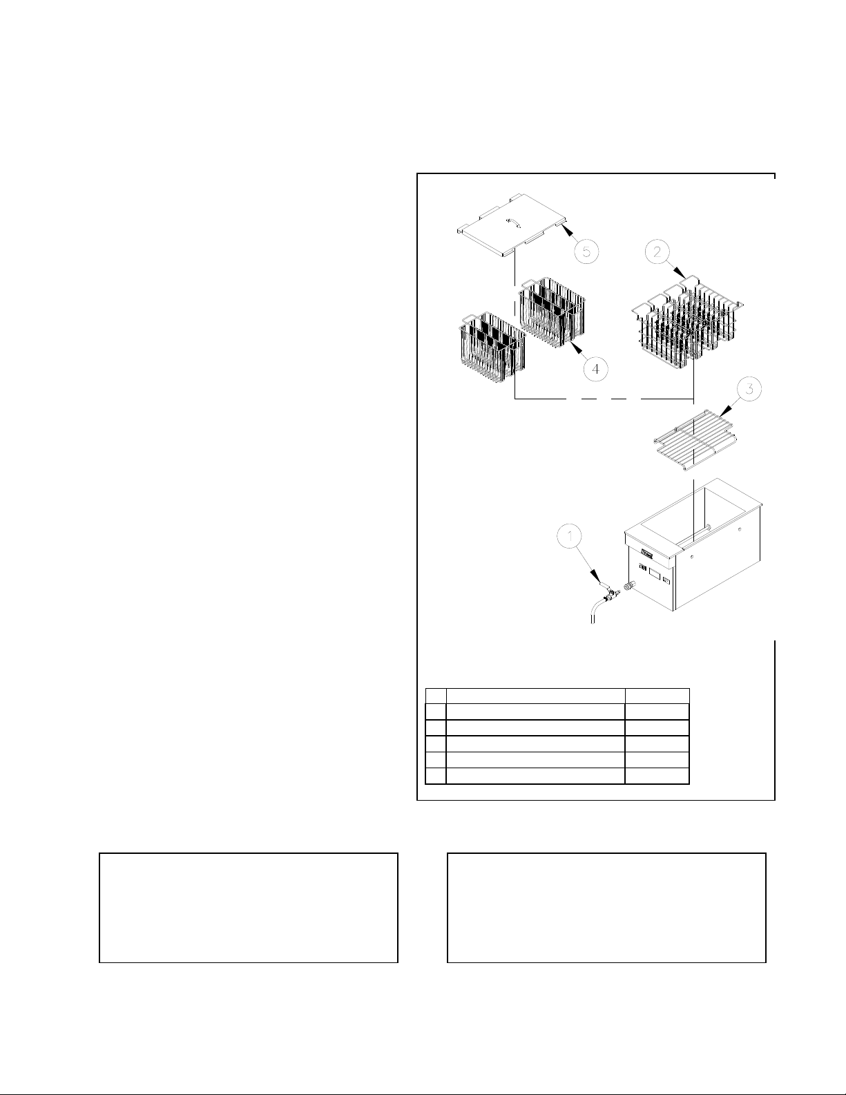
# Description CRTE
1 Drain Hose Standard
2 Soup Rack (Quantity 4) Standard
3 Element Rack Optional
4 3 Product Rack (Quantity 2) Optional
5 Tank Cover for 3 Product Rack Optional
DO NOT sit or stand on this appliance. The
appliance’s front panel, tank, tank cover,
workshelf, drain board is not a step. Serious
injury could result from slipping, falling or
contact with hot liquids.
WARNING
L20-259, rev. 7 (09/13) 2
Page 5
INSTALLATION
1.2. INSTALLATION CLEARANCES
The clearances shown below are for combustible and non-combustible installations and will allow for
safe and proper operation of your appliance.
Combustible Construction Non Combustible Construction
Inches (centimeters) Inches (centimeters)
Back
In addition to the above clearances there must also be at least 16 inches (40.64cm) of aisle space in
front of the unit.
DO NOT obstruct the flow of ventilation, or air openings around the appliance. Adequate
clearance around the appliance is necessary for servicing and proper component ventilation.
Ensure that you meet the minimum clearance requirements specified in this manual.
1.3. INSTALLATION TO COUNTER
After the appliance is in its permanent location, check to ensure that it is level. Level the counter as
needed.
1.4. DRAINAGE CONNECTIONS
The plumbing installation should be done by a licensed plumber and must comply with local and national
codes. The drainage connection is located at the front of the appliance in the bottom left corner and is
equipped with a 3/8" quick disconnect.
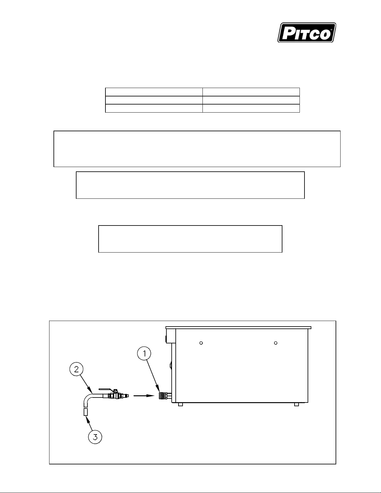
This appliance has a drain that can be inserted into a drainage system. The drain hose must be inserted
into the tank quick disconnect fitting before the appliance can drain correctly. Drain connections for this
appliance are to be made at the end of the 36” (91.44 cm.) long drain hose (3/8” (0.95 cm.) ID tubing).
1) Tank Quick Disconnect Fitting 2) Drain Hose 3) Drainage outlet
Sides
Counter
The appliance should be secured to the counter top to prevent accidental
moving of the appliance and the splashing of hot liquid on the operator.
DO NOT perform leveling procedure when appliance is in
operation or full of hot liquids. Serious injury could result.
6.0" (15.24cm) 0.0" (0.0cm)
6.0" (15.24cm) 0.0" (0.0cm)
4.75" (12.07cm) 0.0" (0.0cm)
WARNING
WARNING
WARNING
3 L20-259, rev. 7 (09/13)
Page 6
CRTE COUNTER TOP RETHERMAILZER INSTALLATION
,
1.5. ELECTRICAL CONNECTIONS
It is advised that this power supply be plugged into a wall receptacle that is controlled by the
ventilation control. This will prevent the appliance from being operated without the ventilator on. The
power requirements for your appliance are listed below.
Voltage/Phase KW Amps
200VAC, single phase 5.5 28
208VAC, single phase 6 29
220VAC, single phase 5 23
230VAC, single phase 5.5 24
240VAC, single phase 6 25
Connecting the appliance to the wrong power supply may damage the appliance and void
the warranty.
CAUTION
WARNING
This appliance must be connected to a power supply having the same voltage and phase as
specified on the data plate located on the inside of the appliance door.
DO NOT attempt to connect the appliance to an electrical supply other then that indicated
on the data plate. Electrical connection should be performed by qualified personnel.
The electrical connection used by this appliance must comply with local codes. If there are
no local codes that apply, refer to the National Electrical Code (NEC), ANSI/NFPA 70 for
installation in the US. In Canada, refer to CSA Standard C22.2 and local codes. In all other
cases
refer to local and national codes and regulations.
The appliance must be grounded in accordance with local code; if there is no local code,
comply with the NEC and ANSI/NFPA No. 70 latest edition (for US and Canadian
installations). In all other cases, refer to local and national codes and regulations. To
comply with European requirements, European models are equipped with an equalizationbonding clamp. An equalization bonding lead must be connected to this clamp to provide
sufficient protection against potential difference. This clamp, located on the rear of the
appliance is marked with the following universal symbol.
WARNING
WARNING
WARNING
WARNING
A country approved all pole circuit breaker with a minimum open contact gap of 3mm must
be used for proper installation. (CE countries)
This equipment must be installed so that the plug is accessible unless other means for
disconnection from the power supply (e.g. a circuit breaker) is provided.
WARNING
WARNING
If this appliance is permanently connected to fixed wiring, it must be connected by means
of copper wires having a temperature rating of not less then 167°F (7 5°C).
All copper wiring for this appliance must be made in accordance with the wiring diagram(s)
located on the appliance.
WARNING
L20-259, rev. 7 (09/13) 4
Page 7

INSTALLATION
Available Power Cords
# Description Standard Hubbell # Mates to
1 Twist Lock NEMA L6-30P HBL2621 HBL2620
2 Shrouded Twist Lock NEMA L6-30P HBL2621S HBL2626
3 Right Angle Straight Blade NEMA 6-30P HBL9331 HBL9330
4 Pin & Sleeve IEC 309-1 or
IEC 309-2
HBL330P6W HBL330C6W or
HBL330R6W
Appliance will be shipped with only one power cord from the listing above.
5 L20-259, rev. 7 (09/13)
Page 8

CRTE COUNTER TOP RETHERMAILZER INSTALLATION
1.6. VENTILATION AND FIRE SAFETY SYSTEMS
Your new appliance must have proper ventilation to function safely and properly. It is very important
to install a fire safety system. Your ventilation system should be designed to allow for easy cleaning.
Frequent cleaning and proper maintenance of the ventilation system and the appliance will reduce the
chances of fire. Ventilation and fire safety systems must comply to local and national codes. Refer to
ANSI 83.11 for a list of reference documents that will provide guidance on ventilation and fire safety
systems.
1.7. INSPECTION
Before you begin filling and operating the appliance, perform the following visual checks:
After the appliance is in its permanent location, check to ensure that it is level. Any additional
leveling that is necessary can be performed as previously described.
Ensure that the probe, heating element, low water level sensor and high temperature limit is in
place and secure. Check the high limit bulb mounting screws to ensure that they are tight.
Review the installation portion of this manual and ensure that all steps have been followed and
executed properly.
1) Probe
2) High Temperature Limit
3) Heating Element
4) Low Water Level Sensor
CAUTION
Be careful not to disturb or damage the probe, low water
sensor and high temperature limit during operation and
cleaning of this appliance.
L20-259, rev. 7 (09/13) 6
Page 9

INSTALLATION
1.8. INITIAL CLEANING
When your appliance is shipped, many of its parts are covered with a thin coat of oil for protection.
Before the appliance is ready for cooking it must be cleaned. This will remove the oil coating and any
foreign matter that may have accumulated during storage and shipment. Refer to the following
procedure to clean the appliance.
Wear protective gloves and clothing when cleaning and draining the appliance and
when disposing of water. The water is extremely hot and can cause severe injuries.
DO NOT leave the appliance unattended during cleaning. Never let the water level
go below the heating element.
1. Read the “operation” section of this manual prior to filling or operating the appliance.
2. The following steps should be followed using a grease dissolving commercial cleaner.
Use a commercial grade cleaner formulated to effectively clean and sanitize food
contact surfaces. Read the directions and precautionary statements before use.
Particular attention must be paid to the concentration of cleaner and the length of
time the cleaner remains on the food contact surfaces.
3. Following the manufacturer’s directions of the cleaning product, clean the tank interior and all
other food contact surfaces.
4. The exterior of the cabinet should be wiped down to remove any dust or foreign matter that
may have accumulated during shipment of the appliance.
5. When cleaning is complete, rinse the inside of the tank thoroughly with cool water. Continue to
rinse the tank until the cleaner has been completely and thoroughly rinsed from the tank.
6. Using a clean dry cloth, wipe out all of the water.
WARNING
CAUTION
WARNING
7 L20-259, rev. 7 (09/13)
Page 10

CRTE COUNTER TOP RETHERMAILZER OPERATION
2. OPERATION
2.1. FILLING THE APPLIANCE
2.1.1. FILLING THE COOKER TANK
It is recommended that the cooker tank is filled with hot water. This will greatly decrease the time
it takes for the appliance to reach operating temperature. Refer to the following procedure to fill
the cook tank prior to operation.
This appliance is not designed for cooking
with oil. Fill with potable water only.
1. If the drain line hose is connected, ensure that the drain
valve is closed.
2. Fill the tank with water until the water reaches the water level line(s), verify that the water
level is above the low water level sensors. The unit may not operate properly if the low
water level sensor is not sufficiently covered with water.
Water must completely cover the heating
elements at all times while appliance is on.
WARNING
2.2. APPLIANCE START UP
Refer to the following procedure to start the appliance prior to operation.
1. If the drain hose is connected, ensure that the drain valve is closed.
2. Fill the cook tank with water. (See section 2.1 “Filling the Appliance”)
3. Press the power switch to the position. Releasing the switch return to the On (I) position.
NEVER operate the appliance with an empty cook tank. It may void the
warranty. Adding water to an empty tank after the elements have been
heated may cause injuries from hot splattering liquids and steam.
WARNING
4. The appliance is now on and heating the water in the cook tank.
2.2.1. High Temperature Limit Switch
The appliance is equipped with an auto-reset
High Temperature Limit switch. The High
Temperature Limit switch will interrupt power to
the element if the internal cook tank reaches an
unsafe temperature. This is to protect the
appliance in the event the water is drained from
the tank while the unit is on, or if the appliance is
left unattended for an extended period of time
allowing the water to boil or evaporate out of the
tank. To reset the switch, refer to Section 4.2.
2.2.2. Liquid Level Control Sensor
The appliance is equipped with a Liquid Level
Safety Control that will interrupt power to the element if the water level is below the fill line. This is
to protect the appliance in the event the water is drained from the tank while the unit is on, or if
the appliance is left unattended for an extended period of time allowing the water to boil or
evaporate below the Liquid Level Sensors, (See Photo at Right). A warning lamp on the front of
the unit alerts the operator that the water level is too low. To restart the appliance, refer to Section
4.3.
CAUTION
DRAIN VALVE CLOSED
WARNING
Dry fired elements are extremely hot, Dry firing the elements
will shorten its service life and may void your warranty.
Tank Capacity
Model Capacity
CRTE 6 Gal. (22.7 Liters)
L20-259, rev. 7 (09/13) 8
Page 11

OPERATION
2.3. COOKING
It is important to keep the cook tank full of water to minimize the chance of boiling the appliance dry
and to keep the water at a level that will provide optimum cooking performance. To ensure the quality
of the food you cook in this appliance, follow the preparation instructions from the food manufacturer.
2.3.1. ADDITIONAL CONTROLLER FUNCTIONS
Some controllers have additional functions not described in this manual. If your appliance’s
controller has additional functions, refer to the controller’s operation manual to access these
functions.
2.3.2. COOKING TIPS
Always follow the food manufacturer’s directions and only use sealed bagged products in this
appliance.
Some products can be reheated and held at the same temperature. If this is the case, the
product may be held in this appliance while still in its vacuum-sealed bag. No separate
holding device required.
Product bag size can be important in reaching the shortest retherm times. Thin bags typically
retherm faster then thicker ones.
Always allow a gap between product bags. This will allow the hot water to circulate around
the entire surface of the product bag, creating good heat transfer and ultimately shorter
retherm times.
Do NOT retherm in boiling water. Boiling water increases your energy and water
consumption and furthermore this appliance is NOT recommended for boiling.
Always follow proper food safety. Refer to FDA and the food manufacturer’s guidelines for
proper handling of the vacuum-sealed product.
Product 140F 200F
Frozen 40 min. 9-10 min.
Thawed 30 min. 7-8 min.
Typical Retherm Times
Appliance Temperature
This table is for reference only.
Please refer to the product
manufacturer’s specifications to
determine exact cook times.
2.4. APPLIANCE SHUTDOWN
Press the power switch to the 0 (OFF) position to shutdown the appliance.
9 L20-259, rev. 7 (09/13)
Page 12

CRTE COUNTER TOP RETHERMAILZER PREVENTATIVE MAINTENANCE
y
3. PREVENTATIVE MAINTENANCE
3.1. DAILY PREVENTATIVE MAINTENANCE
Performing the preventative maintenance steps below on a daily basis will keep your equipment safe
and at peak performance.
3.1.1. APPLIANCE INSPECTION
Check that the high temperature limit,
The power supply must be disconnected
before cleaning and servicing this appliance!
temperature probe, low water level
sensor and the heating element are in the correct position and secured in place.
Check that wires and cords are not frayed or loose in and out of the cabinet.
Che c k around the appliance for loose parts or accessories that need to be secured or other
foreign items (ex: Aerosol cans) that should be removed from the area.
Che c k for water leaks around the drain lines and in and out of the cabinet and around the
appliance.
3.1.2. CLEANING THE COOK TANK
1. Turn the appliance off.
2. Scrub the tank, racks, heating
element and temperature probe
Wear protective gloves and clothing when
cleaning and draining the appliance and
when disposing of water. The water is
extremel
hot and can cause severe injuries.
using a Scotchbrite™ or other mildly
abrasive pad with a commercial type
cleaner specifically designed for
cleaning and sanitizing food contact
Read the operation section of this manual
prior to filling or operating the appliance.
surfaces. Follow the directions and
familiarize yourself with the safe use of this cleaner
prior to using it to clean the appliance. Care must be
taken to remove all the foreign material on the tank and
on components in the tank.
3. Use a cotton swab, or a soft bristle brush to clean off the contact(s) of the low water level
sensor. Build up of mineral deposits on the contacts may cause the unit to improperly
function.
4. When cleaning is complete, rinse the inside of the tank and its components thoroughly with
cool water. Continue to rinse at least twice or until the cleaner has been completely and
thoroughly rinsed from the tank.
3.1.3. CLEANING THE CABINET
1. The outside of the cabinet should be cleaned with a damp cloth and mild detergent to remove
oil, dust, dirt and debris. Be careful not to introduce the detergent into the tank and food zone
regions of the appliance.
3.2. MONTHLY PREVENTATIVE MAINTENANCE
Water can leave mineral deposits inside the tank. Performing the monthly preventative maintenance
steps below will keep your equipment safe and at peak performance. It may be necessary to clean
these components more then once a month.
3.2.1. DELIMING
1. Read the “operation” section of this manual prior to filling or operating the appliance.
2. Following the manufacturer’s deliming instructions, remove deposits from the tank’s interior.
3. When cleaning is complete, rinse the inside of the tank and its components thoroughly with
cool water. Continue to rinse at least twice or until the cleaner has been completely and
thoroughly rinsed from the tank.
4. Using a clean dry cloth, wipe out all of the water.
WARNING
WARNING
WARNING
WARNING
DO NOT leave the appliance
unattended during cleaning.
L20-259, rev. 7 (09/13) 10
Page 13

PREVENTATIVE MAINTENANCE
3.3. ANNUAL/PERIODIC PREVENTATIVE MAINTENANCE AND INSPECTION
This section should ONLY be performed by a qualified service technician as part of a regular kitche n
maintenance program. This inspection should take place a minimum of once a year by an Authorized
Service Technician recommended by Pitco.
The power supply must be disconnected before cleaning and servicing this appliance!
3.3.1. HEATING ELEMENT
Check if the element is mechanically sound and in good condition. Look for scale build up
and inspect for signs of repeated dry firing.
Verify element wires are in good working condition. Look for damage to wires or frayed
insulation. Check that the insulation is dry.
Verify that bulkhead connections/nut is tight and leak free. Look for water stains and wet
surfaces.
Verify amp-draw is within range as compared to the information on the data plate.
3.3.2. TEMPERATURE PROBE & HIGH LIMIT PROBE
Verify probes are in good working condition. Check for damage and that the fasteners are
tightly secured to the tank.
Verify compression fittings are leak free.
Check wiring for loose electrical connections.
3.3.3. LOW WATER LEVEL SENSOR
Verify contacts are clean and free of damage.
Verify that the contacts are properly secured, contacts should not rotate.
Verify there are no water leaks around the contact fluropolymer washers.
3.3.4. CONTROLLER
Perform the following inspection if the appliance is equipped with a temperature controller.
Verify that the controller is in good mechanical condition. Check all lights, displays and
switches to assure that they are working properly. Examine overlay for damage that could
allow moisture to enter.
Check for loose electrical connections.
Verify set temperature. Check temperature 1” above controller probe, if necessary check
probe resistance.
3.3.5. CONTROL BOX & ELECTRICAL COMPONENTS
Verify that heating contactors are in good condition. Check for worn or pitted contacts. Verify
that wires are tight and in good condition.
Verify that all components (transformer, terminal block, relays, drain switches, etc…) are in
good condition. Verify that wires are tight and in good condition.
Verify enclosures are free of leaks. Check for water stains and wet surfaces.
Verify that the covers and panels are in tact and provide a safe condition. Check for loose
parts.
Verify power cord is in good condition. Check for frayed or exposed wires. Verify that the
insulation is in good condition and the attachment to the appliance is tight.
3.3.6. TANK
Verify that the tank is in good condition. Check for scale build up and inspect for signs of
corrosion. Verify that tank is leak free. Check drain overflow (if equipped) for scale build up
and debris blockage.
3.3.7. DRAIN SYSTEM
Verify that drain valve is in good condition. Check for leaks in the seal area and fitting region.
Verify that drain lines are leak free, kink free and in good condition. Check for scale build up
and debris blockage. Verify that the clamps and connections are securely tightened.
WARNING
11 L20-259, rev. 7 (09/13)
Page 14

CRTE COUNTER TOP RETHERMAILZER TROUBLESHOOTING
4. TROUBLESHOOTING
4.1. POWER FAILURE
If electric power is removed for any reason, the appliance will shut down. To restart the appliance,
follow the appliance start up procedure in section 2.2.
DO NOT attempt to operate this appliance during a power outage.
4.2. HIGH TEMPERATURE LIMIT
This appliance is equipped with a high temperature limit switch. The high temperature limit switch will
stop the appliance from functioning if the internal cook tank reaches an unsafe temperature. In the
event that the high temperature limit has tripped, refer to the following steps to reset the switch.
1. Turn the appliance off.
2. Allow the appliance ample time to cool to room temperature.
3. Add water to the cook tank as needed.
4. The high limit switch is now reset and the appliance is ready for start up.
5. Restart the appliance by pressing the power switch to the position and releasing.
DO NOT add water to the tank until it has been given ample time to cool down. Failure
to do so may result in damage to the appliance and/or injury to the operator.
4.3. LIQUID LEVEL CONTROL
This appliance is equipped with a Liquid Level Control. The level control will stop the applia nce from
functioning if the water falls below the liquid level sensors. There is a warning lamp on the front of the
appliance that alerts the operator that the water level is too low, follow these steps to reset the switch.
1 Turn the appliance off.
2 If the heating elements are exposed, allow the appliance ample time to cool to room
temperature.
3 Add water to the nominal fill line in the tank, covering the sensors will reset the liquid level
control.
4 The appliance is ready for start up by pressing the power switch to the position and
releasing.
CAUTION
WARNING
L20-259, rev. 7 (09/13) 12
Page 15

TROUBLESHOOTING
A
A
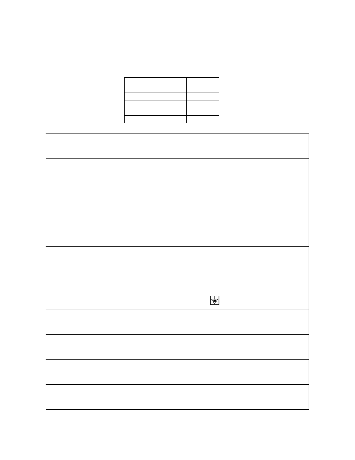
4.4. TROUBLESHOOTING CHART
Problem Probable Cause Corrective Action
Control does not
activate
Appliance stops
heating
4.5. ELECTRICAL SCHEMATIC
No power to appliance Check main building power supply
Circuit breaker tripped Reset power supply Circuit Breaker
I/O swich in the O (off) position
Power cord disconnected Check power cord connection
High temperature limit tripped
Low water level Fill appliance with water level fill line(s)
Circuit breaker tripped Reset power supply Circuit Breaker
High temperature limit tripped
Low water level Fill appliance with water level fill line(s)
Press the power switch to the start Position
and release
llow the appliance to cool to room temperature
and the high limit switch will auto-reset.
llow the appliance to cool to room temperature
and the high limit switch will auto-reset.
13 L20-259, rev. 7 (09/13)
Page 16

CRTE COUNTER TOP RETHERMAILZER TROUBLESHOOTING
4.6. PROGRAMMING INSTRUCTIONS
L20-259, rev. 7 (09/13) 14
Page 17

TROUBLESHOOTING
PROGRAMMING, Cont’d
15 L20-259, rev. 7 (09/13)
Page 18

CRTE COUNTER TOP RETHERMAILZER TROUBLESHOOTING
THIS PAGE INTENTIONALLY LEFT BLANK
L20-259, rev. 7 (09/13) 16
Page 19

TROUBLESHOOTING
THIS PAGE INTENTIONALLY LEFT BLANK
17 L20-259, rev. 7 (09/13)
Page 20

In the event of problems with or
questions about your order, please
contact the Pitco Frialator factory at:
(603) 225-6684 World Wide
Website Address: www.pitco.com
MAILING ADDRESS – P.O. BOX 501, CONCORD, NH 03302-0501
SHIPPING ADDRESS – 10 FERRY ST., CONCORD, NH 03301
In the event of problems with or questions
about your equipment, please contact the
Pitc o Fr i al a to r Authorized Service and Parts
representative (ASAP) covering your area, or
contact Pitco at the numbers listed to the left.
L20-259, rev. 7 (09/13)
 Loading...