

Pioneer XWHTD-640 Service manual
PIONEER CORPORATION 4-1, Meguro 1-chome, Meguro-ku, Tokyo 153-8654, Japan
PIONEER ELECTRONICS (USA) INC. P.O. Box 1760, Long Beach, CA 90801-1760, U.S.A.
PIONEER EUROPE NV Haven 1087, Keetberglaan 1, 9120 Melsele, Belgium
PIONEER ELECTRONICS ASIACENTRE PTE. LTD. 253 Alexandra Road, #04-01, Singapore 159936
PIONEER CORPORATION 2004
÷
Ask user to bring the Transmitter and Wireless Speaker pair set together when
servicing.
XV-HTD640 RRV2930
S-HTD540
XW-HTD640
RRV2943
DVD/CD RECEIVER
DVD 5.1ch SURROUND SYSTEM
SPEAKER SYSTEM
DIGITAL WIRELESS SPEAKER
SYSTEM
This manual
Component System
Service Manual Remarks
RRV2987
CHANNEL
1
2
3
4
ORDER NO.
RRV2987
XW-HTD640
Digital Wireless Speaker System
XW-HTD640
THIS MANUAL IS APPLICABLE TO THE FOLLOWING MODEL(S) AND TYPE(S).
Model Type Power Requirement Remarks
XW-HTD640 KUCXJ AC120V
For details, refer to "Important symbols for good services" .
T-ZZR JULY 2004 printed in Japan
1234
SAFETY INFORMATION
A
This service manual is intended for qualified service technicians; it is not meant for the casual
do-it-yourselfer. Qualified technicians have the necessary test equipment and tools, and have been
trained to properly and safely repair complex products such as those covered by this manual.
Improperly performed repairs can adversely affect the safety and reliability of the product and may
void the warranty. If you are not qualified to perform the repair of this product properly and safely, you
should not risk trying to do so and refer the repair to a qualified service technician.
WARNING
This product contains lead in solder and certain electrical parts contain chemicals which are known to the state of California to
B
cause cancer, birth defects or other reproductive harm.
Health & Safety Code Section 25249.6 – Proposition 65
NOTICE
(FOR CANADIAN MODEL ONLY)
Fuse symbols (fast operating fuse) and/or (slow operating fuse) on PCB indicate that replacement
parts must be of identical designation.
REMARQUE
(POUR MODÈLE CANADIEN SEULEMENT)
Les symboles de fusible (fusible de type rapide) et/ou (fusible de type lent) sur CCI indiquent que
C
les pièces de remplacement doivent avoir la même désignation.
(FOR USA MODEL ONLY)
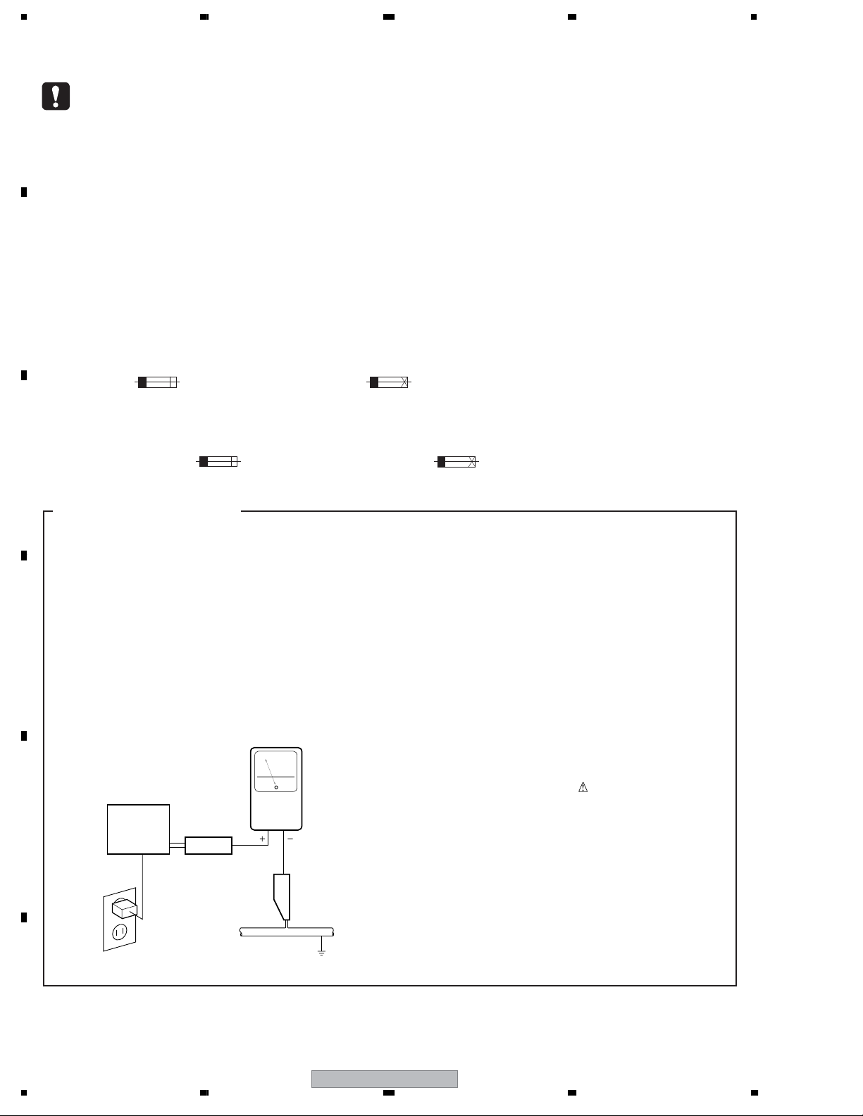
1. SAFETY PRECAUTIONS
The following check should be performed for the
continued protection of the customer and service
technician.
LEAKAGE CURRENT CHECK
Measure leakage current to a known earth ground
(water pipe, conduit, etc.) by connecting a leakage
current tester such as Simpson Model 229-2 or
D
equivalent between the earth ground and all exposed
metal parts of the appliance (input/output terminals,
screwheads, metal overlays, control shaft, etc.). Plug
the AC line cord of the appliance directly into a 120V
AC 60 Hz outlet and turn the AC power switch on. Any
current measured must not exceed 0.5 mA.
Leakage
current
E
Device
under
test
Also test with
plug reversed
(Using AC adapter
plug as required)
Test all
exposed metal
surfaces
AC Leakage Test
tester
Reading should
not be above
0.5 mA
Earth
ground
ANY MEASUREMENTS NOT WITHIN THE
LIMITS OUTLINED ABOVE ARE INDICATIVE
OF A POTENTIAL SHOCK HAZARD AND
MUST BE CORRECTED BEFORE RETURNING THE APPLIANCE TO THE CUSTOMER.
2. PRODUCT SAFETY NOTICE
Many electrical and mechanical parts in the appliance
have special safety related characteristics. These are
often not evident from visual inspection nor the
protection afforded by them necessarily can be obtained
by using replacement components rated for voltage,
wattage, etc. Replacement parts which have these
special safety characteristics are identified in this
Service Manual.
Electrical components having such features are
identified by marking with a
on the parts list in this Service Manual.
The use of a substitute replacement component which
does not have the same safety characteristics as the
PIONEER recommended replacement one, shown in the
parts list in this Service Manual, may create shock, fire,
or other hazards.
Product Safety is continuously under review and new
instructions are issued from time to time. For the latest
information, always consult the current PIONEER
Service Manual. A subscription to, or additional copies
of, PIONEER Service Manual may be obtained at a
nominal charge from PIONEER.
on the schematics and
F
2
1234
XW-HTD640
5678
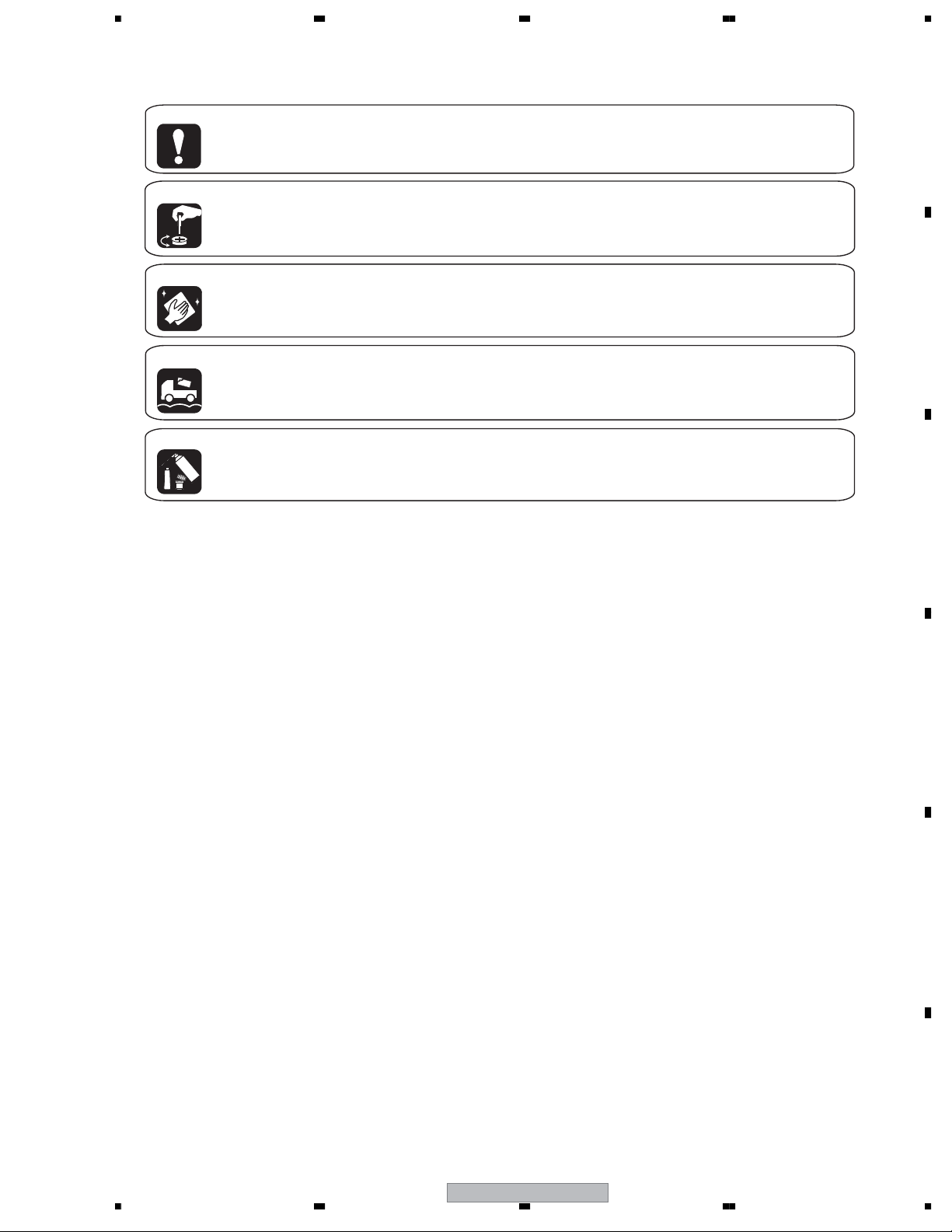
[ Important symbols for good services ]
In this manual, the symbols shown-below indicate that adjustments, settings or cleaning should be made securely.
When you find the procedures bearing any of the symbols, be sure to fulfill them:
1. Product safety
You should conform to the regulations governing the product (safety, radio and noise, and other regulations), and
should keep the safety during servicing by following the safety instructions described in this manual.
2. Adjustments
To keep the original performances of the product, optimum adjustments or specification confirmation is indispensable.
In accordance with the procedures or instructions described in this manual, adjustments should be performed.
3. Cleaning
For optical pickups, tape-deck heads, lenses and mirrors used in projection monitors, and other parts requiring cleaning,
proper cleaning should be performed to restore their performances.
4. Shipping mode and shipping screws
To protect the product from damages or failures that may be caused during transit, the shipping mode should be set or
the shipping screws should be installed before shipping out in accordance with this manual, if necessary.
A
B
5. Lubricants, glues, and replacement parts
Appropriately applying grease or glue can maintain the product performances. But improper lubrication or applying
glue may lead to failures or troubles in the product. By following the instructions in this manual, be sure to apply the
prescribed grease or glue to proper portions by the appropriate amount.For replacement parts or tools, the prescribed
ones should be used.
C
D
56
XW-HTD640
E
F
3
7
8

1234
CONTENTS
SAFETY INFORMATION..................................................................................................................................... 2
1. SPECIFICATIONS ............................................................................................................................................ 5
2. EXPLODED VIEWS AND PARTS LIST ............................................................................................................ 6
A
B
C
D
2.1 PACKING SECTION .................................................................................................................................. 6
2.2 TRANSMITTER SECTION......................................................................................................................... 8
2.3 WIRELESS SPEAKER SECTION........................................................................................................... 10
2.4 AMP SECTION ........................................................................................................................................ 12
3. BLOCK DIAGRAM AND SCHEMATIC DIAGRAM ..........................................................................................14
3.1 BLOCK DIAGRAM ................................................................................................................................... 14
3.2 OVERALL WIRING DIAGRAM................................................................................................................. 16
3.3 TX ASSY .................................................................................................................................................. 18
3.4 MAIN, POWER, OP, PRI and SW ASSYS ............................................................................................... 20
3.5 AMP and REGULATOR ASSYS .............................................................................................................. 22
3.6 TX MODULE(1/3) ..................................................................................................................................... 24
3.7 TX MODULE(2/3) ..................................................................................................................................... 26
3.8 TX MODULE(3/3) ..................................................................................................................................... 28
3.9 RX MODULE(1/4) .................................................................................................................................... 30
3.10 RX MODULE(2/4) .................................................................................................................................. 32
3.11 RX MODULE(3/4) .................................................................................................................................. 34
3.12 RX MODULE(4/4) .................................................................................................................................. 36
3.13 WAVEFORMS........................................................................................................................................ 38
4. PCB CONNECTION DIAGRAM ..................................................................................................................... 39
4.1 TX ASSY .................................................................................................................................................. 40
4.2 OP and SW ASSYS ................................................................................................................................. 41
4.3 MAIN ASSY ............................................................................................................................................. 42
4.4 POWER and PRI ASSYS......................................................................................................................... 44
4.5 AMP and REGULATOR ASSYS .............................................................................................................. 46
4.6 TX MODULE ............................................................................................................................................ 48
4.7 RX MODULE............................................................................................................................................ 50
5. PCB PARTS LIST ........................................................................................................................................... 52
6. ADJUSTMENT ............................................................................................................................................... 56
7. GENERAL INFORMATION ............................................................................................................................. 57
7.1 DIAGNOSIS ............................................................................................................................................. 57
7.1.1 TROUBLESHOOTING........................................................................................................................ 57
7.1.2 NOTES ON REPLACE OF PARTS ..................................................................................................... 58
7.1.3 DIAGNOSIS OF THE AMPLIFIER SECTION..................................................................................... 58
7.1.4 PROTECTION CIRCUIT..................................................................................................................... 59
7.1.5 DISASSEMBLY ................................................................................................................................... 61
7.2 IC ............................................................................................................................................................. 64
8. PANEL FACILITIES ........................................................................................................................................ 73
E
F
4
1234
XW-HTD640
5678
1. SPECIFICATIONS
A
Digital Wireless Speaker System (XW-HTD640)
General
Digital Wireless Speaker System (Transmitter /
Wireless speaker)
Transmitter
AC adapter:
Power requirements . . . . . . . . . . .AC120V, 60 Hz
Power consumption . . . . . . . . . . . . . . . . . . . .. 8W
Rated output . . . . . . . . . . . . . . . . . . . .12V/300mA
Power consumption (without AC adapter) . ..2 W
Input . . . . . . . . . . . . . . . . . . . . . . . . . . . . .RCA jack
Weight . . . . . . . . . . . . . . . . . . . . . . . .0.3 kg / 11 oz
Dimensions . . . . . 166 (W) x 56 (H) x 112 (D) mm
6
9/16 (W) x 2 3/16 (H) x 4 7/16 (D) in.
Wireless speaker
Power requirements . . . . . . . . . . .AC120V, 60 Hz
Power consumption . . . . . . . . . . . . . . . . . . . .57W
Amplifier characteristics
Maximum power output . . . . . . . . . . . . . .25W/ch
Speaker unit. . . . . . . . . . . . . . .7 cm cone type x2
Weight . . . . . . . . . . . . . . . . . . . . .
Dimensions (without
antenna) . . . . . . . .
16
RMS(1kHz, THD 10%,4Ω)
4.0 kg / 8lb 14oz
430 (W) x 180(H) x 138 (D) mm
15/16 (W) x 7 1/8 (H) x 5 7/16(D) in.
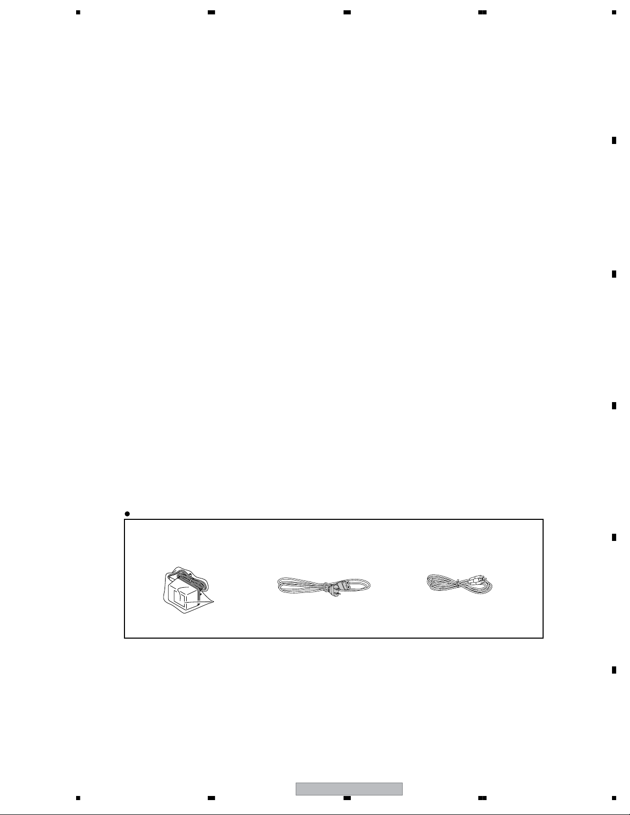
Accessories (XW-HTD640)
AC adapter
RCA stereo cord
Warranty card
AC Power cord
. . . . . . . . . . . . . . . . . . . . . . . . . . . . . ..1
. . . . . . . . . . . . . . . . . . . . . . . . . ..1
. . . . . . . . . . . . . . . . . . . . . . . . . . ..1
. . . . . . . . . . . . . . . . . . . . . . . . . . . .1
B
C
Accessories
• AC Adapter
(AWR7006 : KUCXJ)
• AC Power Cord
(ADG7021 : KUCXJ)
D
• RCA stereo cord(L=1.5m)
(XDE3045)
E
F
56
XW-HTD640
5
7
8
1234
2. EXPLODED VIEWS AND PARTS LIST
NOTES:
A
Parts marked by "NSP" are generally unavailable because they are not in our Master Spare Parts List.
The mark found on some component parts indicates the importance of the safety factor of the part.
Therefore, when replacing, be sure to use parts of identical designation.
Screws adjacent to mark on product are used for disassembly.
For the applying amount of lubricants or glue, follow the instructions in this manual.
(In the case of no amount instructions, apply as you think it appropriate.)
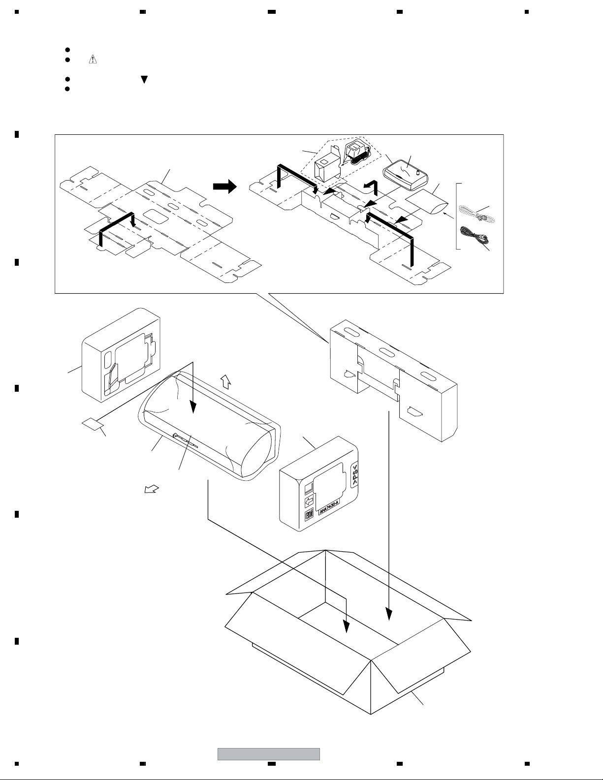
2.1 PACKING SECTION
B
C
2
1
4
Transmitter
8
5
3
FRONT
11
13
D
E
9
Wireless Speaker
TOP
10
F
6
1234
XW-HTD640
12

>
5678
PACKING SECTION parts List
No. Description Part No.
Mark
1 Accessory Box Wiz AHB7091
2AC Adapter AWR7006
3 RCA Stereo Cord XDE3045
NSP 4 Literature Bag AHG1180
5AC Power Cord ADG7021
6• • • •
7• • • •
8Polyethylene Bag VHL1051
9Packing Sheet (large) AHG7010
10 Pad L AHA7430
11 Pad R AHA7431
12 Packing Case AHD8288
NSP 13 Warranty Card ARY7045
A
B
C
D
E
56
XW-HTD640
F
7
7
8
1234
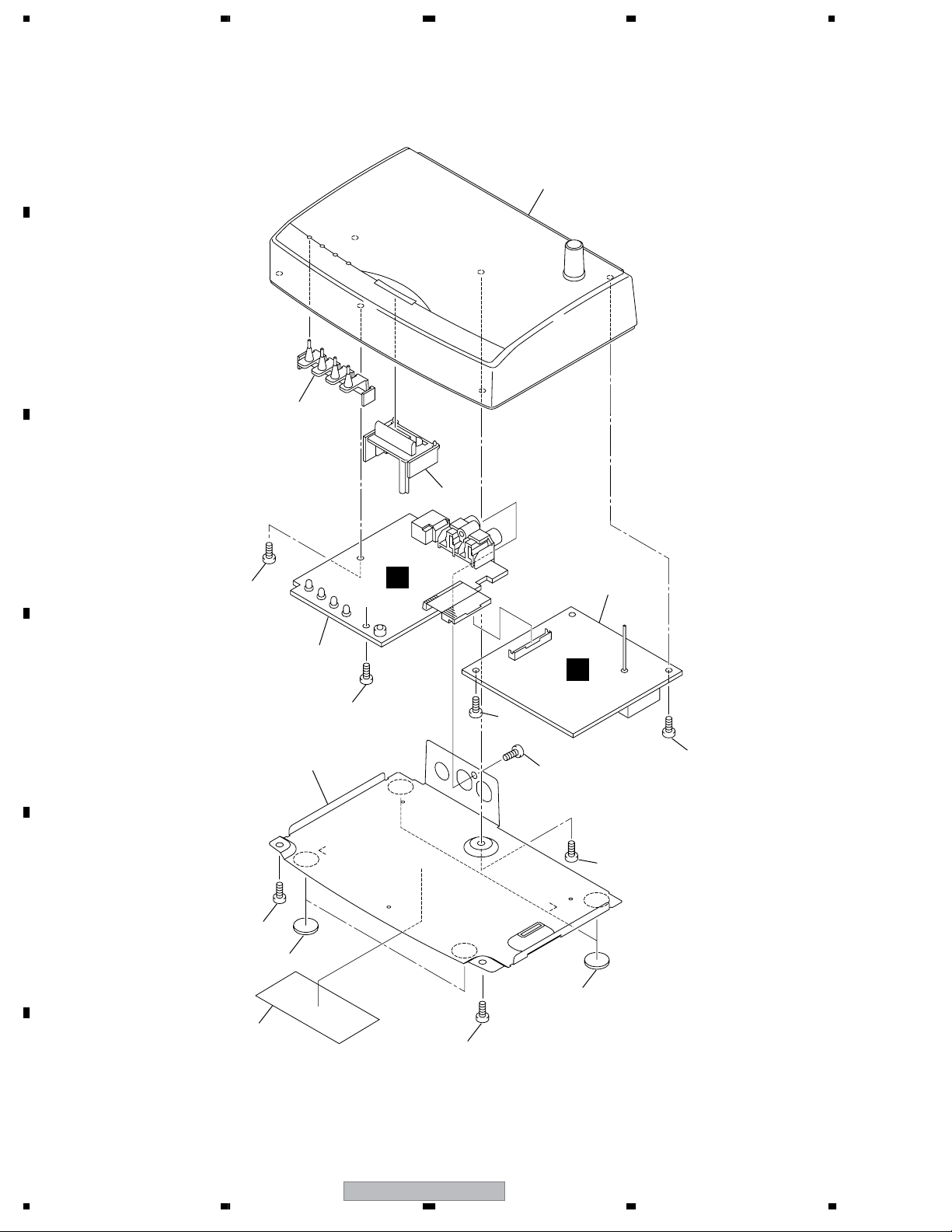
2.2 TRANSMITTER SECTION
A
B
3
4
5
C
8
1
A
2
J
D
E
8
8
6
8
8
8
8
7
7
9
F
8
1234
XW-HTD640
8

*
5678
TRANSMITTER SECTION parts List
No. Description Part No.
Mark
1 TX Assy AWU8228
2 TX Module AXF7010
3Top Panel Wiz AAK8205
4 CS Lens AAK8133
5 CS Button T AAD7729
6 Chassis T ANA7157
7 Leg AEB7090
8TORX Screw *
NSP 9 Name Label T AAL7362
ABA7111
A
Use TORX driver GGK1028.
B
C
D
56
XW-HTD640
E
F
9
7
8
1234
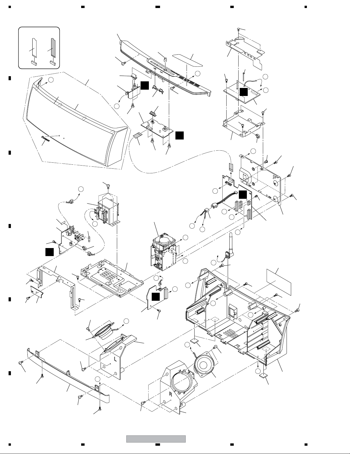
2.3 WIRELESS SPEAKER SECTION
A
B
C
D
47
47
NON-CONTACT
SIDE
36
47
CONTACT SIDE
A
50
5
F
18
6
42
48
41
47
K
25
22
L
J
47
7
38
46
39
32
34
4
K
49
E
40
33
3
46
51
24
M
47
D
13
49
49
44
K
19
J
23
C
31
48
48
B
17
49
47
46
9
10
47
46
Refer to
"2.4 AMP MODULE L-2CH"
F
23
16
8
D
E
G
I
F
A
H
C
2
D
47
11
H
G
I
L
C
46
21
1
52
46
M
E
46
46
F
10
1234
37
46
46
12
46
28
B
46
E
20
46
B
12
29
43
20
XW-HTD640

>
>
5678
WIRELESS SPEAKER SECTION parts List
No. Description Part No.
Mark
1 MAIN Assy AWU8229
2POWER Assy AWU8230
3 OP Assy AWU8231
4 SW Assy AWU8233
5 PRI Assy AWU8234
NSP 6 Jangan Buang PCB
7 RX Module AXF7011
NSP 8 AMP Module L-2CH AXQ7253
9Power Transformer (T1) ATS7366
10 Fuse (FU1 : 1.6A) REK1110
No. Description Part No.
Mark
50 Fuse Cade AAX7520
NSP 51 GETTER EX AAX8043
NSP 52 Name Label (Ku) AAL7353
A
11 4P Cable Assy ADX7431
12 Speaker B70AC50-52C
13 13P FFC/60V ADD7467
14 • • • •
15 • • • •
16 Chassis ANA7156
17 Rear Panel ANC8270
18 PCB Angle ANG7464
19 Shield Cover A ANK7112
20 Rubber Leg AEB7318
NSP 21 PCB Spacer (3x6) AEC7156
22 Push Rivet AEC7221
23 Mini Clamp AEC7373
24 Top Barrier AEC7496
25 PCB Binder VEF1040
26 • • • •
27 • • • •
28 Baffle WIZ L AMD7011
29 Baffle WIZ R AMD7012
30 • • • •
NSP 31 PC Support VEC1749
32 MIC Knob AAB7262
33 Slide Knob AAC7052
34 Power Button AAD7722
35 • • • •
B
C
D
36 Name Plate AAM7013
37 Front Panel AMB7876
38 Grille Assy AXG7225
39 Operation Panel AAK8196
40 OP Lens AAK8198
NSP 41 SP Grille WIZ AAK8197
NSP 42 Jersey Net AAR7011
43 Rear Case Assy AXG7224
44 Screw BBZ40P060FTC
45 • • • •
46 Screw BPZ40P100FNI
47 Screw BBZ30P060FTC
48 Screw VPZ30P080FNI
49 Screw BBZ30P080FNI
56
XW-HTD640
E
F
11
7
8
1234
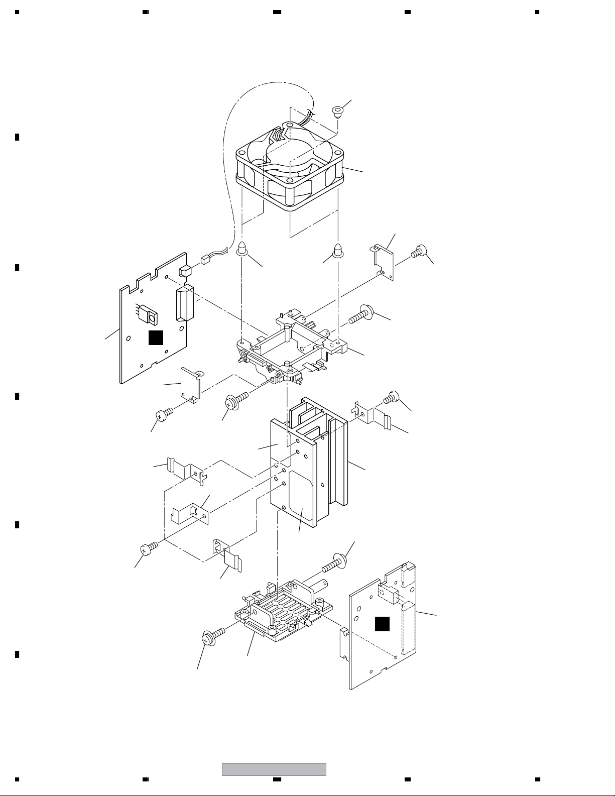
2.4 AMP SECTION
A
B
7
3
8
11
7
13
5
4
13
7
C
2
D
I
8
13
14
12
9
10
14
15
9
15
E
9
1
H
6
13
F
12
1234
XW-HTD640

5678
AMP SECTION parts List
No. Description Part No.
Mark
1 AMP Assy AWU7968
2 REGULATOR Assy AWU7969
3 DC Fan Motor AXM7025
4 Heat Sink ANH7169
5Fan Mold AMR7470
6 Rear Mold AMR7437
7 Insulation Rubber AEB7256
8 Insulation Plate AND7055
9 FET Bracket A ANG7432
10 PCB Holder ANG7472
A
11 Mica Sheet A AEE7049
12 Mica Sheet B AEE7050
13 Screw (3x10) ABA7117
14 Screw BPZ30P080FNI
15 Screw BBZ30P060FTC
B
C
D
56
XW-HTD640
E
F
13
7
8
1234
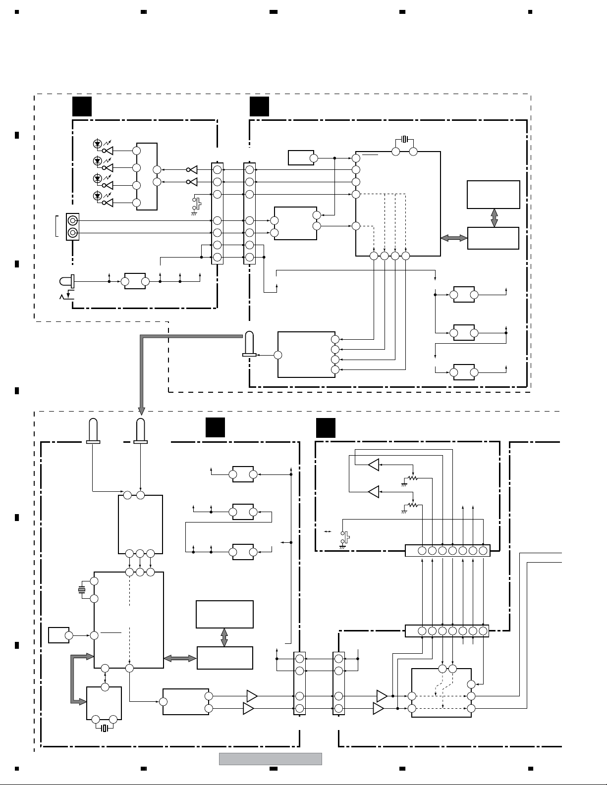
3. BLOCK DIAGRAM AND SCHEMATIC DIAGRAM
3.1 BLOCK DIAGRAM
A
TRANSMITTER SECTION
TX ASSY
A
IC8501
BU4052BCF
Ch.1
Ch.2
Ch.3
B
Ch.4
JA8202
L
R
INPUT
WIRERESS
JA8001
DC IN
Ch Select SW.
Q8501
11
Q8502
15
9
14
12
IC8001
BA09FP
10
Ch. select
Q8503
Q8504
9V REG.
V+12 V+9RF
1 3
Q8506
Q8505
VA+9
CN8201
VD+9
(12P)
11
12
LED 2
3
LED 1
4
CHSEL
2
LIN
6
RIN
8
V+9RF
V+9RF
C
TX MODULE
J
H2
(12P)
PLD02
3
PLD01
4
CHANNELSEL
2
6
2
8
1
11
A/D Converter
12
+9V
ANT1
12
U3
AIC1680
System
Power On Reset
1
SDTO
U9
U23
AWD601TX
RF Tx Module
RFINANT
13
9
CHAN2
CHAN1
CHAN3
AINL
AINR
AK5380VT
DATA
X1
24.576MHz
RESET
11
CHANNELBIT1
64
CHANNELBIT2
12
CHNNELSEL
8
SDTO
58
1
8
9
7
3 5
CLKIN CLKOUT
Freesystems
RFOUT
CHANNEL1
CHANNEL2
31 33 34 35
U1
FS2105TX
Tx Chip
CHANNEL3
AIC1734-50CXA
REG.
+9V
3 2
NCP1117ST50T3
5V REG.
3 2
AIC1734-33CXA
3.3V REG.
D5V
3 2
52806-0910
EEPROM Prog.
Interface
EEPROM for FS
U21
U6
U22
H10
U7
RFSUPPLY+
A5V
D3V3
D
E
F
14
X3
24.576MHz
U20
AIC1680
System Reset
3
VCXO1-VCXO8
RX MODULE
K
OP ASSY
D
ANT2ANT3
U12
RFANT1
RFANT2
AWD601RX
RF Rx Module
DATA6CHAN18CHAN4
3
5
7
NC7SPU04
VCXO
2 4
12.288MHz
31
CLKIN
RFINSDTI
CLKOUT
U2
FS2105RX
Freesystems Rx Chip
RESETIN
VCLKIN
58
54
6
U18
P5X
X2
1714
U16
35
CHANNEL3
11
40
CHANNEL2
A3V3
D5V
VOUTL
DATA
2
VOUTR
U28
PCM1742KE
D/A Converter
AIC1734-50CXA
5V REG.
D5V
2 3
U19
AIC1734-33CXA
3.3V REG.
D3V3
2 3
U17
NCP1117ST50T3
5V REG.
A5V
2 3
H6
52807-0910MOLEX
EEPROM Prog.
Interface
U11
EEPROM for FS
7
8
3
NJM4558
DAC Filter
RFSUPPLY+
+9V
+9V V+9RF
12
11
7
5
1
U24
H3
(12P)
8
6
SURROUND
V+9
V+9
LOUT
ROUT
STEREO
1
2
5
7
CN3701
(12P)
5
7
IC3051
NJM4558MD
3
1
CN3504
CN3051
3
5
IC3301
NJM4558MD
VR3051
VOL
(13P)
7 5 8 1 6
LVIN
RVIN
LVOUT
7 9 8 1 6
(13P)
5 14
Y1 X1
X0
1
12
7
Y0
1
BU4052BCF
IC3001
Selecter
RVOUT
X (Lch)
Y (Rch)
VREF
VA+9
VA+9
VREF
4413
VA+9
VREF
9
13
3
13
Mode
XW-HTD640
1234
5678
SPEAKER SECTION
POWER ASSY
C
+B
D13
CN12
(13P)
CN13
(13P)
D16
D15
D14
1 4 7 8 101111
AC
VDET
+B (FAN H)
+B (UNPRE+5)
1 4 7 8 10
D12
+B
+B
D11
CN11
A
B
PRI ASSY
F
T1
POWER
TRANSFORMER
MAIN
2
MAIN
121
1
2
FU1
CN1CN2
NEUTRAL
LIVE
2
1
J1
21
MAIN ASSY
B
CN4
1
2
AC IN
SW ASSY
E
S1
C
D
V+9RF
AMP MODULE L-2CH
AMP ASSY
H
LIN
RIN
MUTE
+B
+B
+B
1
3
6
REF5V
7
9
PRE REG.
+B
14
15
1
2
7
5
8
10
Circuit
for Power
CN3302
(15P)
CN3303
(10P)
Amp
REGULATOR ASSY
I
UPRE5V
PRE12V
+B
PRE12V VP
PRE REG.
Circuit
for +5V
Short DET.
FAN DET.
XW-HTD640
R IN
CN3651
1
3
6
REF5V
7
PRE12V
9
14
15
CN3304
(15P)
VA+9VD+9
CN3305
(10P)
UPRE5V
1
PRE5V
V+5
2
7
5
8
10
REF5V
PRE12V
XPROTECT
56
L IN
1
13
TDA8560Q
Power Amp.
Q3305
1
2
IC3301
11
MODE
DC FAN
MOTOR
7
9
4
CN3301
(5P)
5
4
1
2
L +OUT
R +OUT
5
4
1
2
CN3306
(5P)
J3401
L +
L -
R +
R-
8
INSIDE
SPEAKER
E
F
15
1234
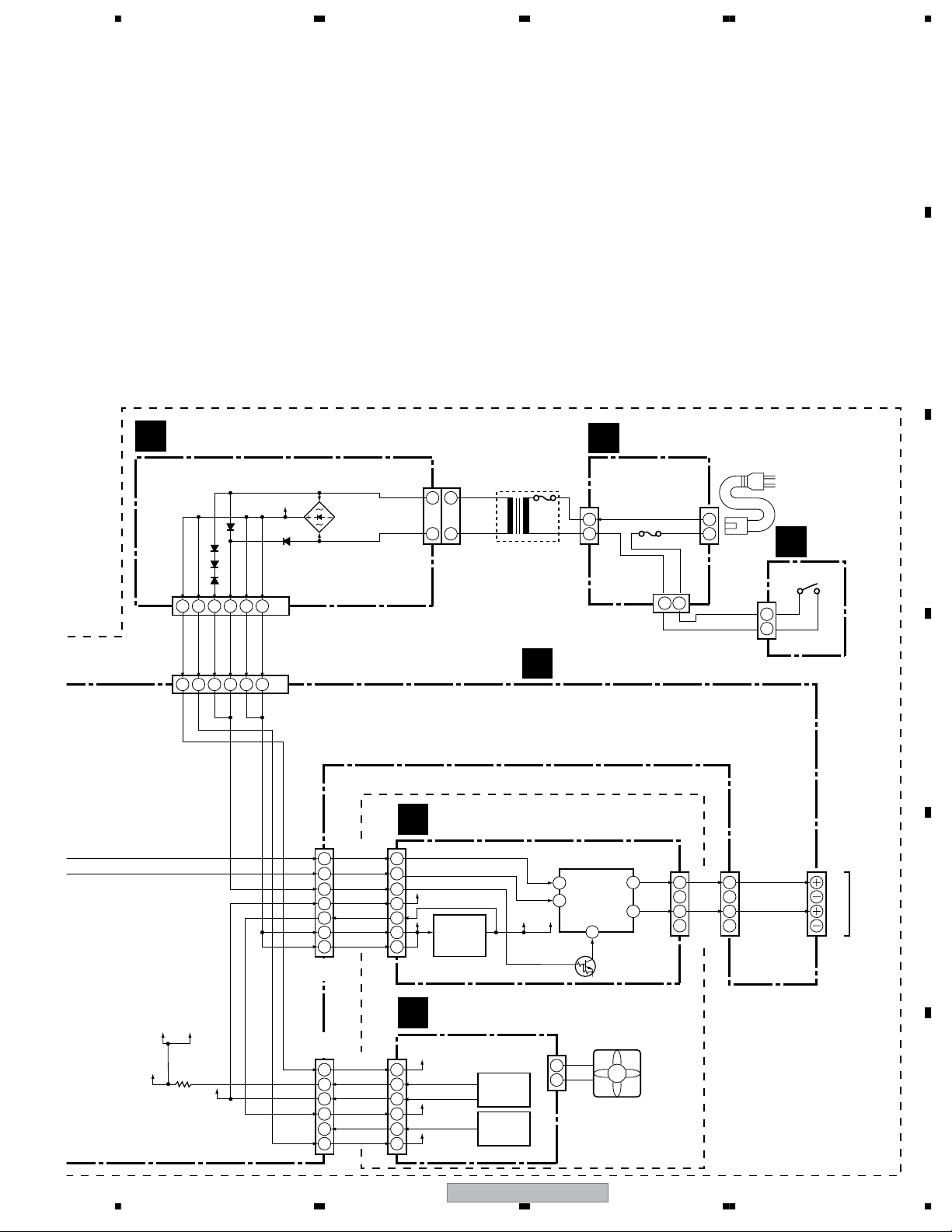
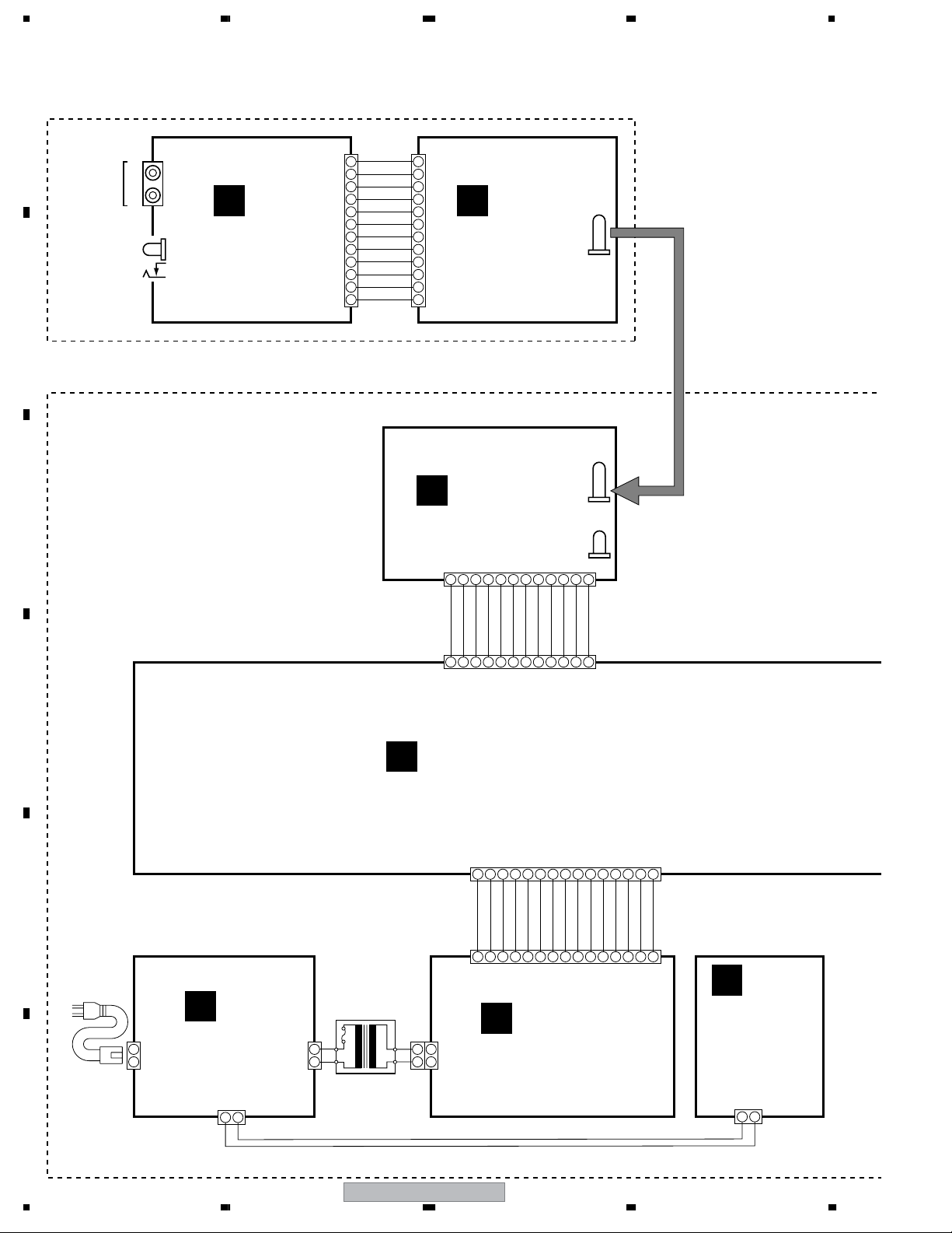
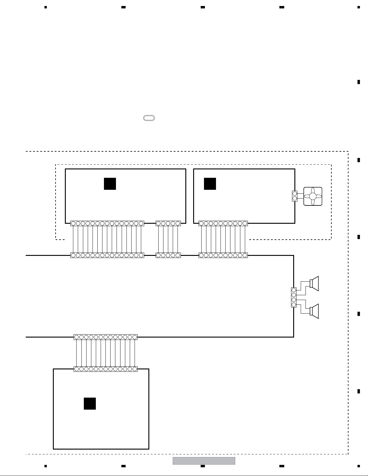
3.2 OVERALL WIRING DIAGRAM
• Transmitter Section
A
WIRERESS
INPUT
DC IN
B
• Speaker Section
C
R
L
JA8202
JA8001
A
TX ASSY
(AWU8228)
CN8201 H2
STATUS (NC)
1
2
3
4
5
6
7
8
GNDRF
9
GNDRF
10
11
12
CHSEL
LED 2
LED 1
GND
LIN
GNDA
RIN
V+9RF
V+9RF
1
2
3
4
5
6
7
8
9
10
11
12
K
J
TX MODULE
(AXF7010)
RX MODULE
(AXF7011)
H3
12 11 10 9 8 7 654
312
ANT1
ANT2
ANT3
D
E
POWER CORD
: ADG7021
F
CN1 CN2
PRI ASSY
NEUTRAL
2
1
(AWU8234)
LIVE
POWER
TRANSFORMER
: ATS7366
1
2
V+9
V+9
GND3GND
GND
GND
LOUT
ROUT
ERROR
STATUS
CH. select
SCAN_MODE
11
1
2
4
5
CN3701
MAIN ASSY (AWU8229)
B
CN13
CN12
T1
CN11
212
1
6
1 2 3 4 5 6 7 8 91012
GNDFAN
GNDPRE5
+B (FAN H)
+B (UNPRE+5)
1
2
3
4
C
10
7
8
9
12
11 13 14 15
+B
GNDREG
GNDPRE12
6
7AC8
VDET
9
GNDSW
10
11+B13
PROTECT
12
GNDRF
5
POWER ASSY
(AWU8230)
GNDP14GNDP
15
E
SW ASSY
(AWU8233)
F
16
J1
12
XW-HTD640
CN4
12
1234
5678
NOTES: • When ordering service parts, be sure to refer to “EXPLODED
VIEWS and PARTS LIST” or “PCB PARTS LIST”.
• The > mark found on some component parts indicates the
importance of the safety factor of the part.
Therefore, when replacing, be sure to use parts of identical
designation.
• : The power supply is shown with the marked box.
AMP MODULE L-2CH (AXQ7253)
A
B
CN3302
1 2 3 4 5 6 789
LIN
1
CN3304
CN3051
RIN
GNDA
GNDA
2
3
4
1 2 3 4
Mode
GNDD
RVOUT
H
AMP ASSY
(AWU7968)
STBY
MUTE
REF5V
SENSE (PRE12V)
5
6
7
8
5 6 7 8 9
LVIN
GNDA
GNDA
GNDA
LVOUT
101211 13 14 15
GNDP
H/L CONT
GNDPRE12V
11
10
12
101211 13
RVIN
GNDA
CH. select
GNDP
13+B14+B15
VA+9
PRE12V
9
VREF
CN3301
1 2 3 4 5
R–
R+
GNDP
1
2
3L–4L+5
CN3306
I
REGULATOR ASSY
(AWU7969)
CN3303
1 2 3 4 5 6 789
PRE5V
UPRE5V
1
PRE12V
GNDPRE5
SENSE (PRE+5V)
2
3
4
5
H/L CONT
6
CN3305
REF5V
XPROTECT
7
8
10
+B
FANGND
10
9
CN3651
J3401
SL+ (R+)
SL– (R–)
SR– (L–)
SR+ (L+)
DC FAN
MOTOR
+
1
–
2
R ch
SPEAKER
1
2
3
4
: B70AC50-52C
L ch
SPEAKER
: B70AC50-52C
C
D
E
CN3502
10
11
1
2
3
4
5
6
7
8
9
13
12
D
OP ASSY
(AWU8231)
56
XW-HTD640
F
17
7
8
1234
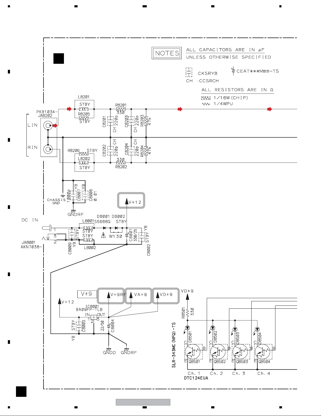
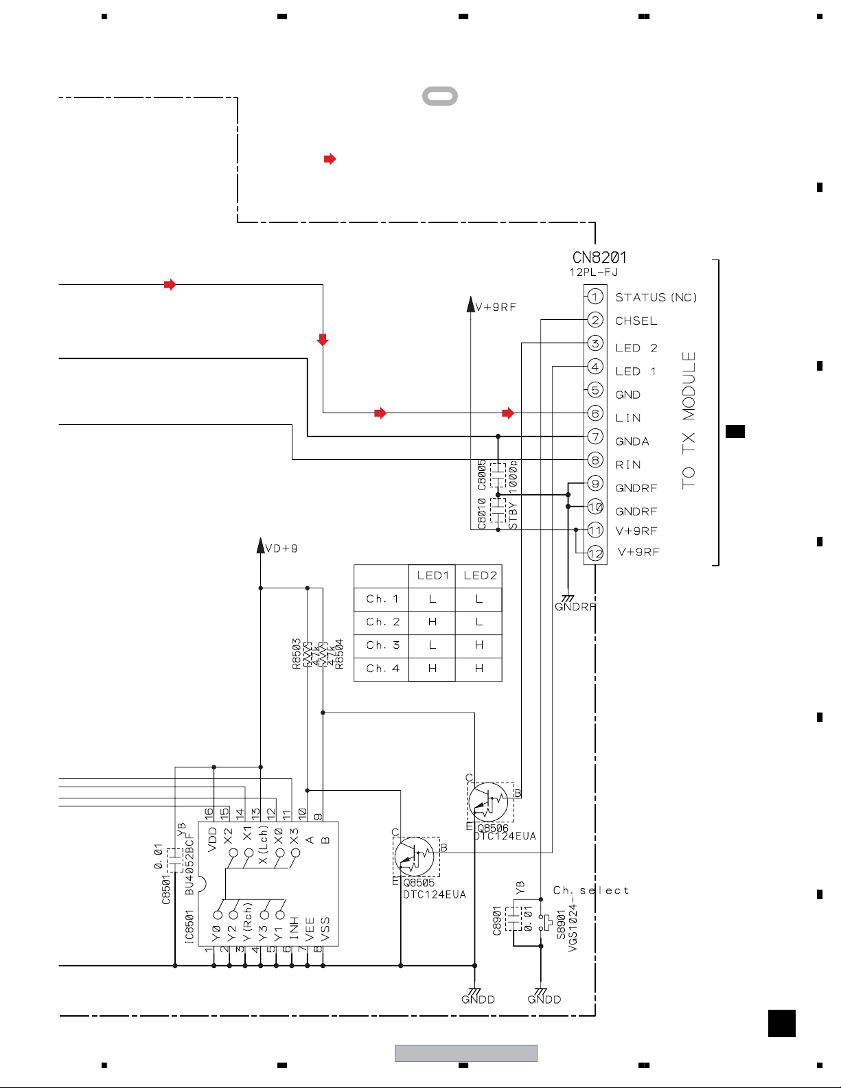
3.3 TX ASSY
A
B
INPUT
WIRERESS
TX ASSY (AWU8228)
A
C
D
E
F
A
18
1234
XW-HTD640
5678
: The power supply is shown with the marked box.
: AUDIO SIGNAL ROUTE (L ch)
A
B
H2
J 2/3
C
CH Select SW.
D
E
Switches
S8901 : Ch. select
F
56
XW-HTD640
A
19
7
8
1234
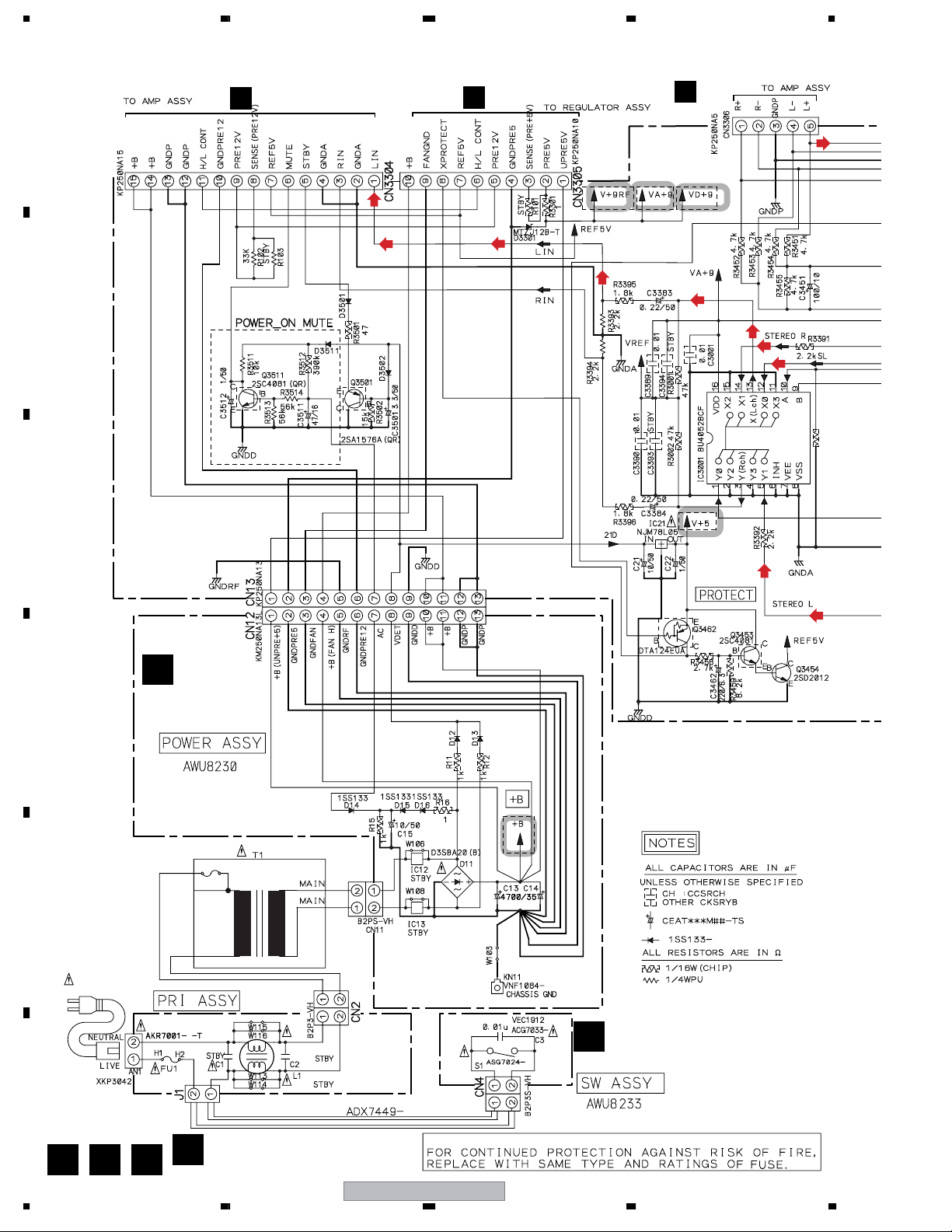
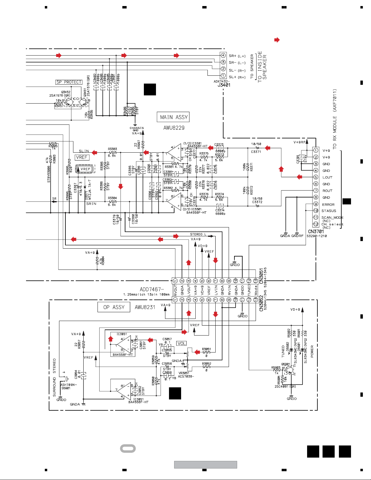
3.4 MAIN, POWER, OP, PRI and SW ASSYS
CN3302
A
B
H
CN3303
I
CN3301
H
C
C
D
E
POWER ASSY
(AWU8230)
POWER TRANSFORMER
T1
ATS7366
POWER CORD
ADG7021
F
B C F
20
SW ASSY
E
(AWU8233)
REK1110
1.6A
• NOTE FOR FUSE REPLACEMENT
PRI ASSY (AWU8234)
F
1234
CAUTION
XW-HTD640
5678
MAIN ASSY
B
(AWU8229)
: AUDIO SIGNAL ROUTE (L ch)
H3
K 2/4
A
B
C
Switches
S5901 : SURROUND/STEREO
S5902 : Ch.select
56
OP ASSY (AWU8231)
D
: The power supply is shown with the marked box.
XW-HTD640
7
D
E
F
DB E
21
8
1234
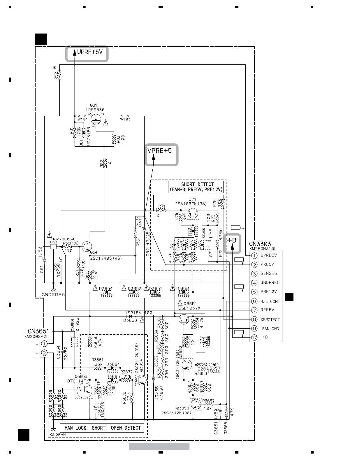
3.5 AMP and REGULATOR ASSYS
REGULATOR ASSY (AWU7969)
A
B
I
C
D
E
DC FAN
MOTOR
14.7V
8.4V
16.4V
B
CN3305
26.4V
F
I
22
1234
XW-HTD640
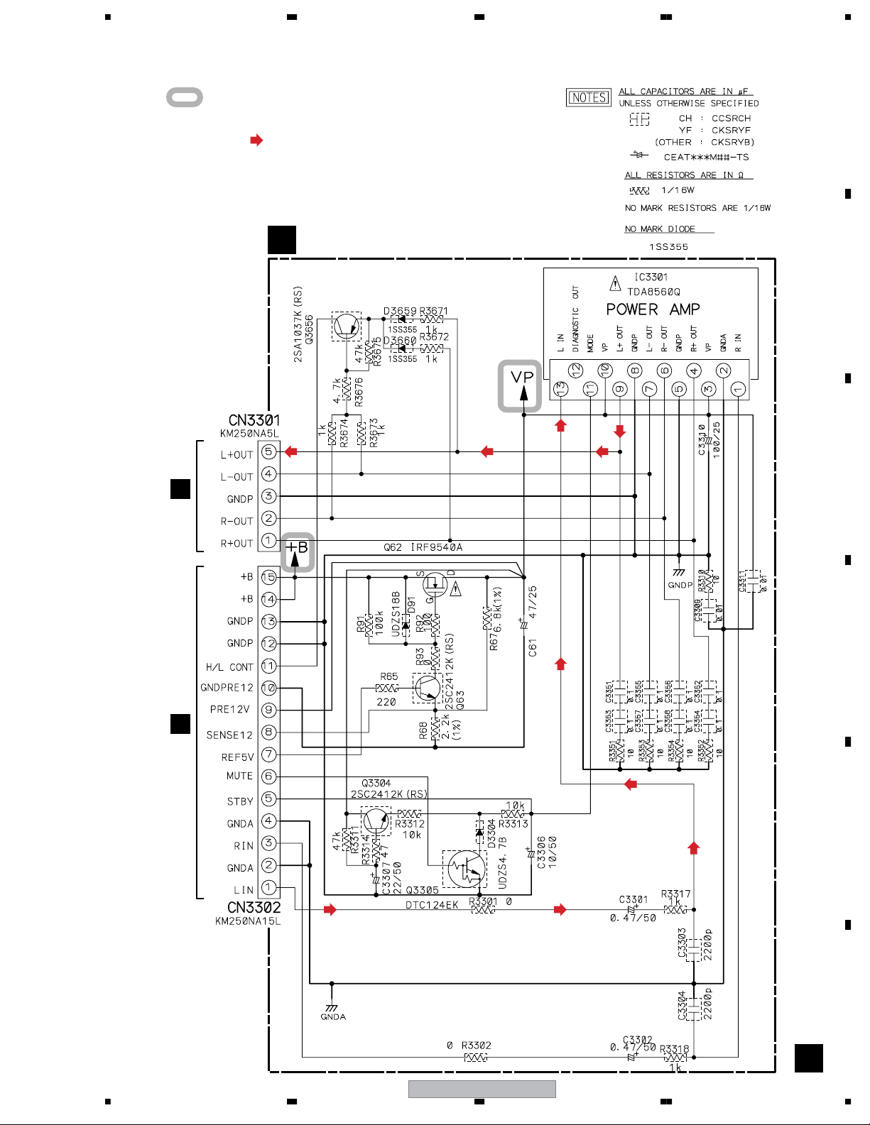
5678
B
CN3306
: The power supply is shown with the marked box.
: AUDIO SIGNAL ROUTE (L ch)
AMP ASSY (AWU7968)
H
A
B
C
B
CN3304
D
E
F
56
XW-HTD640
H
23
7
8
 Loading...