

Page 1
Operating
Instructions
LASER
DISC
PLAYER
VP-l000
,------IMPORTANT
The
serial
number
rear
panel.
Please
enclosed
This
Caution;
formance
fied
exposure.
WARNING:
SHOCK
THIS
warranty
is
fo r your
here-in
security
Use
of
of
procedures
may
TO
HAZARD I DO
APPLIANCE
STURE.
for
this
equipment
write
this
card
and
.
controls
result
or
other
in
PREVENT
TO
NOTICE----...
is
located
serial
number
keep
in a
secure
adjustments
than
those speci-
hazardous
radiation
FIRE
NOT
RAIN
EXPOSE
OR
@PIONEER
on
on
your
area.
or
per -
OR
MOI-
the
~-----CONTENTS------------~
SAFETY INSTRUCTIONS
FEATURES
REAR
CONNECTIONS
FRONT
TOP
PANEL
BEFORE
OPERATION
TROUBLE-SHOOTII\JG
MAINTENANCE
SPECIFICATIONS
..
PANEL
PANEL
FACI
OPERATION
......
...
....
..
.. ..
....
FACILITIES
. . . . . . . . . . . . . . . . . . . .
FACILITIES
LITIES
......
.. . ...
. . . . . . . . . . .
. . . . . . . . . . . . 7
. . . . . . . . . . . . . . 8
.......
.
.. . ..
...
..
. .
. . . .
..
.....
....
.......
.
.. . ....
. .
.......
..
..
"
...
..
. . . 10
...
.
..
..
..
..
. 9
. 14
..
15
. . 15
2
3
4
5
Page 2

SAFETY
INSTRUCTIONS
READ
RETAIN
HEED
FOLLOW
WATER
• The appliance should
•
INSTRUCTIONS -All
struction
s should
INSTRUCTIONS -The
should
be
retained
WARNING -All
the operating
instructions
INSTRUCTIONS -All
structions should
AND
MOISTURE
ample, ne
tub
00
extremely
, in a
not
handle the
ar a bathtub,
wet
basement ,
dangerous because
the safety and operating in-
be
read before the appliance
operating
for
future
reference.
warnings on the appliance and in
should
be
adhered
operating and
be
followed.
not
be
used near water washbowl,
or
power
near a s
cord
kitchen
wimming
with
you
shock.
Moisture
•
and the appliance
appliance
room
To
stand
switching
rises
LOCATION
form s in
is
or
if
the
prevent
In
its new surroundings
it
the operating sections
's
performance
brought
from
temperature
impairing
on, or ensure
gradually.
- The appliance should
will
cool surroundings
of
the
room
performance, let the appliance
for
about
that
the
be
location.
•
VENTILATION
its
location
ventilation.
- The appliance s
or
pos
ition
does
For
example, the appliance should
not
hould
interfere
situated on a bed, sofa, rug, or similar surface
block
the
ventilation
openings.
is
operated.
instructions
to.
use
for
sink,
laundry
pool,
etc.
wet
hands. This
may get
be
an
electric
of
the appliance
impaired
if
into a warm
rises
suddenly.
an
hour
before
room
temperature
installed in a stable
be
situated
so
that
with its proper
not
that
may
in-
ex-
the
be
POWER
away
OUTDOOR
antenna is connected
antenna system
tion
Section
No.
grounding
ing
of
unit,
ments
is
LINES -An
from
power
ANTENNA
outdoor
lines.
GROUNDING
to
is
grounded
against voltage surges and
810
of
the
National
70-1978, provides
of
the mast and supporting
of
the lead-in
information
wire
to
grounding conductors,
connection
for
EXAMPLE
NATIONAL
PER
ai,
the
b)
Mast
ground
wire
to
grounding electrodes, and require-
grounding
OF
ANTENNA
ELECTRICAL
c)
Antenna
discharge
unit
electrode.
antenna should
the antenna
so
as
to
built
Electrical Code,
with
an
antenna discharge
location
See
GROUNDING
CODE
To
........
Antenna
be
located
-
If
an
out
side
terminal,
be
sure the
provide some protec·
up
static charges .
ANSI/NEPA
respect
structure,
of
antenna-discharge
to
proper
ground-
unit,
size
Fig. A.
AS
INSTRUCTIONS
terminal
HEAT
- The appliance s
(including
SOUR
as
CES -
sources such
appliances
POWER
to a power supply
ating
instructions
GROUNDING -The
that
the
grounding
POWER-CORD PR
• Power-supply cords s
not
likely
to
be
upon
or
against
hould
be
situated away
radiators, heat registers, stoves , or
amplifiers)
Th
e appliance s
only
of
or
as
marked on the appliance.
precautions
of
an
appliance
the
that
produce heat.
hould
type
described in the oper-
that
should
is
not
defeated.
OTECTION
hould
be
routed
to
walked on or pinched by items placed
them,
paying
particular
cords at plugs, convenience receptacles, and the
where
they
exit
from
the appliance.
•
Always
power
The cord may
2
take
hold
outlet; do
be
of
the plug
not
unplug
damaged
if
it
you
to
by
keep
unplug
pulling
pulling
from
heat
other
be
conn ected
be
taken so
that
they
attention
point
it
from
on the cord.
on
it.
are
to
the
_ _..__ _ _ _ _
a)
Use
No.1
0 AWG copper
No. 17 AWG copper-clad steel
as
ground
b) Secure lead·in wire
unit
lators , spaced
meters) apart.
c)
Mount
where lead-in enters house.
wi
res
for
both
and mast ground
from
4 feet (1.22 meters)
antenna discharge
from
wire
Ground
Grounding
*-
driven
8'
(2.44
meters)
or
No.8
or
bronze wire,
mast and lead-in.
antenna
to
unit
to
house
as closely
clamps
electrode
into
the
earth
Fig. A
AWG
aluminum
or
antenna discharge
with
stand·off
to 6 fe
et
as
possible
or
larger
insu·
(1 .83
to
Page 3

SAFETY
INSTRUCTIONS
.
NONUSE
should
a long period
OBJECT
so
the enclosure
SERVICING
appliance
tions.
Pioneer
that
PERIODS
be
unplugged
of
ti
me.
AND
LIQUID
objects
do
not
through
- The user should
beyond
All
authorized
that
other
servicing should
service center.
- The
from
power
the
outlet
ENTRY
fall and
openings.
described in the
liquids
not
cord
of
when
- Care should
are
not
attempt
operating
be
contacted
FEATURES
Future technologies come to your home
Th
is
system
ed
on
the
pickup
focused on the signal patterns and the
reflected
ordinary
wear on the disc
prints
interfere
laser beam
In
other
so
video disc handling
High
Besides the video signal,
channels
production
Audio
ratio
is
or
less,
with
conventional
Although
is
required
commend
example,
quality
uses
a laser beam
the laser disc. There
system and the disc
is
converted
phonograph record , there
or
dust
on the laser disc surface, this
with
reproduction
is
focused
words,
fidelity
as
FM signals.
is
also possible.
frequency
55dB
or
making
connection
for
that a hi-fi
is
used
of
the laser disc.
into
the reproduced signal.
or
the
pickup.
about
the recorded signal surface
is
easy and requires
stereo sound
audio
Therefore,
response
more, and
this high
phonograph
normal video and
to
is
total
fidelity
to
an
stereo system, one
take
full
to
detect
the signal record-
is
no
physical
itself
Even
of
picture
1.1
mm
is rec·orded on
40Hz -20
harmonic
·stereo source comparable
records
ordinary
audio
advantage
contact
since the laser beam
variation
is
no
abrasion and
if
there
will
or
audio
under
the disc surface.
is
no
stereo
or
kHz,
distortion
or
FM broadcasts.
television set
reproduction
from
of
the appliance
left
unused
be
taken
spilled
into
to
service the
instruc·
nearest
between
of
the
light
Unlike
are
finger-
not
usually
because the
not
exposed,
special care .
two
sep~Hate
bilingual
signal-to-noise
is 0.3%
is
all
that
, we re-
Pioneer,
the
hi-fi
sound
for
an
no
re-
for
DAMAGE
be
fied service personnel
• The
• Objects have fallen,
appliance,
• The appliance
• The appliance does
exhibits a marked
• The appliance
damaged.
each
features
Although
is
constant
features,
per side since the
1,800
outer
REQUIRING
serviced by Pioneer
power-supply
or
revolution,
are
possible.
the
linear
it
does have a
rpm
at the
circumference.
cord
has
been exposed
change in
has
so a number
extended
velocity
rotational
inner
SERVICE
authorized
when:
or
the plug
or
liquid
not
appear
performance;
been
dropped,
of
play
disc, also
disc, does
maximum
speed
circumference
- The appliance should
service center or
has
been damaged;
has
been spilled
to
rain;
or
to
operate
or
additional
known
not
offer
playing
continuously
time
to
into
normally
or
the enclosure
performance
as
the
CLV
such
additional
of
one
varies
600
rpm
quali·
or
the
or
or
hour
from
at
the
Built-in computer control provides multiple
performance features and
From
the
inner
to
the
laser disc
tinuous
signal
covering one
ference, each frame
ber. Thanks
be
can
be
is
also a
random
by
motion,
operations
you
has a maximum
spiral
pattern.
for
one video
full
revolution.
to
microcomputer
played repeatedly
be
played several times
skipped
frame
"super
access
number
fast
operate
for
fast-forward
that
action,
are
remarkably
VP-1000
action"
within
On the
picture
is
to
will
and etc.
laser disc player.
easy
operation.
outer
circumference, the Pioneer
of
54,000
CAV
frame
Beginning at the inside circum-
recorded along
control,
provide a still picture, each frame
for
slow
or
reverse
feature
find
a specific frame
15
seconds, and
from
easy,
"tracks"
(standard
is
recorded on one track
motion,
so
that
as
will
play)
with
its frame num-
a single frame
and tracks can
reproduction.
called frame number
automatically
you
can
point.
Such
be
apparent when
in
a con-
disc, the
There
play
slow
complex
can
Both
standard play
(CLV)
laser
disc
can
(CAV)
be
played, and
automatically detects these
play
accordingly.
The
standard play disc, also
angular
1,800
cumference
time
On the
velocity
rpm
per side.
CAV
from
and provides a
disc, one video
disc, spins at the same,
the
inner
circumference
maximum
known
and extended play
VP-l000
laser
discs
and
as
the
CAV
or
constant
to
the
of
30
minutes
picture
frame
is
recorded
constant
speed
outer
cir-
playing
for
of
Infrared wireless remote control
With
the
optional
operations can
light.
Remote
sible.
Adaptable
VP-1000
for a PCM
available
is
PCM
RU-1000
be
controlled
control
to
PCM digital audio
equipped
adaptor
(pulse code
using a
with
special
to
decode the signal
modulation)
remote
from
connection
output
is
possible.
control
unit
virtually
a distance via infrared
wire
is
also pos-
disc
reproduction.
jacks
for
provision
from
soon-to-be-
digital audio discs.
aT
all
3
Page 4
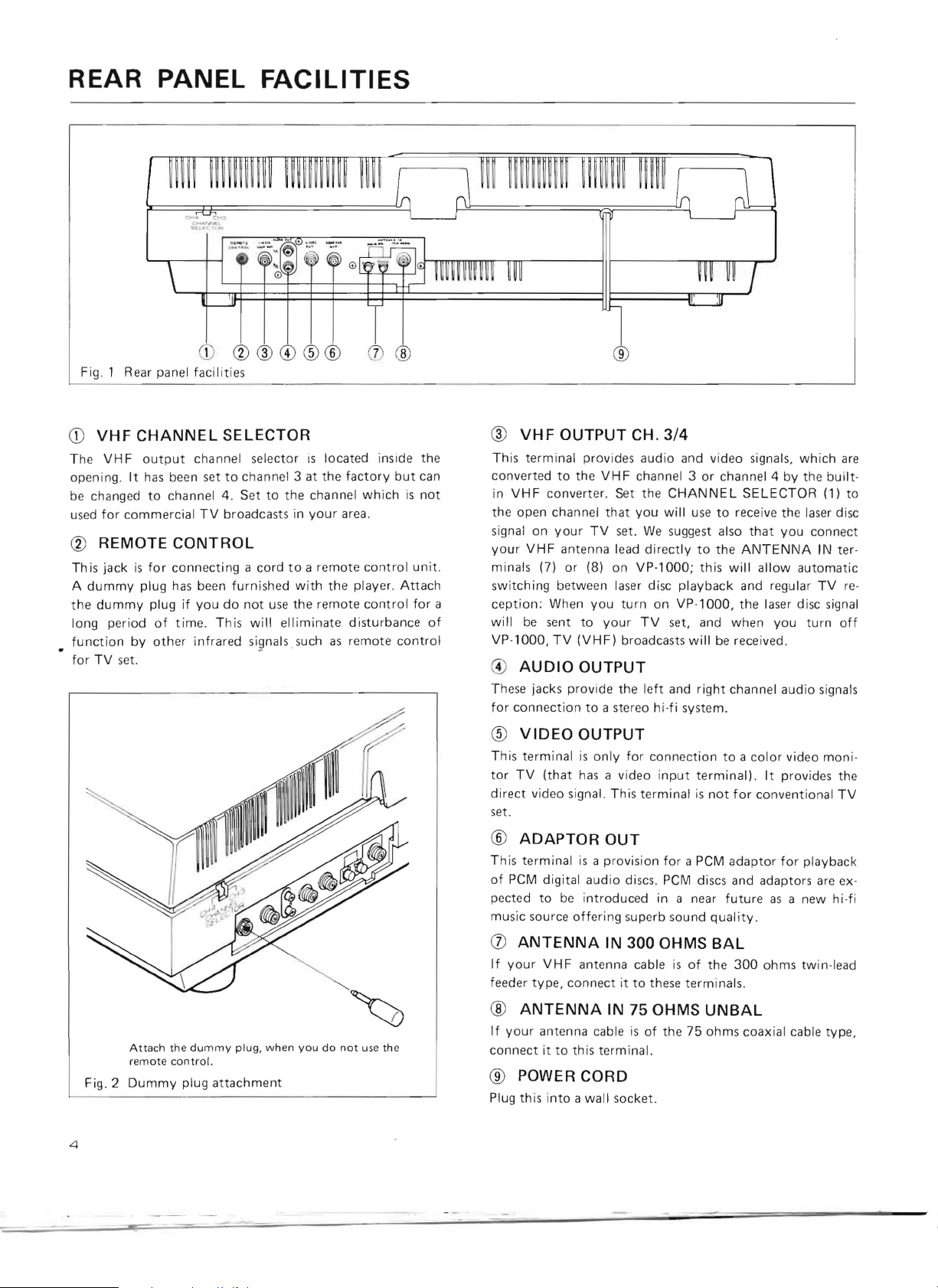
REAR PANEL
FACILITIES
Fi
g.
1 Rear panel
Q)
VHF
CHANNEL
The
VHF
output
openin
g.
It
has
be
used
changed
for
to
commercial
® REMOTE
Thi
s jack
is
for
A
dummy
t he
long
function
for
dummy
per iod
TV
set.
by
plug
plug
of
other
facilities
SELECTOR
channel selector
been set
chann
to
el
4. S
TV
broadcasts in
CONTROL
connecting
has been
if
time.
furnished
you
do
This will elliminate disturbance
infrared
is
located inside
channel 3 at the
et
to
the channel
your
a cord
to a remote
with
the
not
use
the
remote
si9nals such
as
factory
area
remote cont
but
which is not
.
control
player.
control
Att
the
can
unit.
ach
for
of
ro l
®
®
VHF
OUTPUT
Th
is
terminal
converted
VHF
in
the open channel
signal on
your
VHF
minal s (7)
switching
a
c
eption
will
be
VP-
1000, TV
G)
AUDIO
T
hese
jacks provide the
for
connection
®
VIDEO
This terminal
tor
TV
direct video signal. This
set.
provides
to
the
converter
your
antenna lead
or
(8) on
between laser disc
: When
sent
to
(VHF)
OUTPUT
to
OUTPUT
is
(that
has
CH.
3/4
audio
and vid eo
VHF
channel 3
. S
et
the
CHANNEL
that
you
will use
TV
set.
We
sugges
dir
ect
ly
VP-l000; this will allow
playback
you
turn
on VP -
your
TV
set, and
broadcasts
a stereo hi-fi system.
only
for
a video
term
will
left
and right channel audio signals
connection
input
inal
is not
sig
nals,
whi
or
channel 4 by the built-
SELECTOR
to
receive the laser disc
t also
that
you
to
the
ANTENNA
automatic
and regular
1000,
the laser d is
when
you
be received.
to a color
terminal).
for
video
It
provides the
convent
ch
(1)
connect
IN
ter -
TV re-
c signa l
turn
moni
ional
TV
are
to
off
-
4
Fig. 2
Attach
remote
Dummy
the
dummy
control.
plug
plug,
when
attachment
you
do
not
use th e
®
ADAPTOR
This terminal
of
PCM
digital
pected
music source
(j)
If
feeder
®
If
connect
to
ANTENNA
your
VHF
type,
ANTENNA
your
antenna cable
it
to
OUT
is
a provision
audio
be
introduced
offering
IN
antenna cable
connect
IN 75 OHMS
this
terminal.
it
® POWER CORD
Plug this i
nto
a wall socket.
for
a PCM
adaptor for playback
discs. PCM discs and adaptors
in a
near future
superb sou nd
300
OHMS BAL
is
of
to
these terminals.
Quality.
the
300
as
ohms
a new
twin-lead
UNBAL
is
of
the 75 ohms coaxial cable
are
type,
ex-
hi-fi
Page 5

CONNECTIONS
TV
Video
monitor
(optional
TV
connection)
VHF
Antenna
Fig.3.
000
::10
00
LID
D
DO
Remote
Control Unit
~
RU-lOOO
c::=:J
(opt
c::::=:J
DO
ional
connection)
Overall connections diagram
300-ohms
1.
2.
3.
4.
Cu
t
OU
Twi
st
Unscrew
wire
toothed
Tighten
feeder
preparation
t the cen
ter
the lead wire.
the
terminal
arou nd
the stud,
washer and
the
terminal
port
the
ion
cap and
hose.
cap.
Stereo
Amplifier
(optional
.
wind
between
the
the
30006
PCM
Adapter
(op
tional
connection)
Power
Plug
Speaker
System
75-ohms F type
1.
Strip
2.
Slip
cable and then
3. Insert
wire
4.
Tighten
AN
TENN
A IN
AL
750
UNBAL
plug
the
end
of
the accessory
bend
the F type
and
the
shield.
the
ring.
preparation
the cable.
ring
back
plug
over
the
between
Wall
Socket
the
coaxial
shield.
the
core
Fig.4
Antenna
connections
Unit
:
I I
I I
L
__
..J..
____
_ ~___
_l
Un
it: mm
5
Page 6

CONNECTIONS
CONNECTIONS
1.
Remove
terminal(s)
ANTENNA
feeder antenna cable
as
ANTENNA
antenna cable
to
order
BA L terminal.
2.
An
plied
VHF
end
terminal
IN
5.
chase
cable
lead feeder
antenna terminals.
your
on
IN
shown in the
IN
(75
the end
accessory cable
terminal,
If
of
the
to
connect
with
VP·l000. Connect
OUT
terminal
to
the
VHF
on
your
prepare the end
your
TV
a 75
ohms·to·300
to
the
adaptor.
to
TO YOUR
VHF
antenna cable
your
TV
set, and
terminal(s)
left
300
ohms),
cable,
it
to
with F type
on
IN
(75
TV
has
no 75 ohms antenna
the
TV's
on
(300
ohms) prepare
of
fig. 4 and
ohms
BAL
an F type
as
shown in the
the
ANTENNA
VP·l000
ohms, unbalanced, F
set.
If
your
of
ohms adaptor and
Then
connect
VHF
TV
from
the
VHF
connect
Vp·l000.
plugs at
one end
TV
the cable
IN
the cable
For
twin·lead
the
wire
connect
terminals. For coaxial
plug
must
be
right
of
fig.
IN
75 ohms
both
ends
of
this cable
and
connect
has
the
(300
the
type
no F type
as
shown in fig.
terminal,
connect
adaptor's
ohms balanced)
ANT
to
leads
to
fitted
4,
is
other
jack)
VHF
twin-
the
the
in
UN·
sup·
to
pur·
the
3.
Next,
used
set
same
4. Plug
socket
nection
through
1. I nsert a
selector
2.
Slide
channel
Fig.6.
set
your
TV
to
for
commercial
VHF
CHANNEL
channel accordingly
AC
power cord
(120V,
Channel selector
60Hz).
procedure
your TV.
small
open
i ng.
the
selector
4;
slide
(flat
to
for
to
the
channel 3
TV
broadcasts in
SELECTOR
as
for
VP-l000
This completes the standard con-
video and audio
blade)
the
left
right
or
4, whichever
on
shown in fig. 6.
into
screwdriver
(vi e
for
channel
into
wed
from the rear)
3.
your
area. Then
VP·1000
a standard
reproduction
the
channel
is
to
for
not
the
wall
G
-
~--
-
CtD
\'HF
our
J
.
~~
do
75-ohm
coaxial
1.
Strip
2.
3.
4 .
the
Prepare the
Loosen
the
Tighten the
end
Oi
cable
preparation
of
the
cable
as
end
three
three
as
shown
screws,
screws
shown
in
steps 2
insert
firmly.
the
Unit:
in
and
cable.
mm
step 1.
3.
OPTIONAL CONNECTIONS
1. Stereo amplifier
Vp·l000
from
use
AU
channel
stereo
Place the
between the
volume
laser discs.
the
two
D10
OUT
AUX
amplifier
control
can
acce
TV
two
reproduce
To
ss
jacks on
input
or
receiver.
set
(to
stereo speakers and
for
two
take
full
ory
audio
VP-l000
(or
tape
which
best results.
channel stereo
advantage
connection
or
tuner
you
have the cable connected)
/
to
shut
of
cords
the
input)
this
left
jacks on
off
the
hi-fi
signals
capability,
to
connect
and right
your
TV
set's
.i
6
Fig.5
Connections
to
a standard
TV
set
Fig.7
Connections
to
a stereo pre-main
amplifier
Page 7

CONNECTIONS
2.
Video monitor
If
you
are
using a video
input
terminal),
VIDE
on
the
In this
to
audio
audio
O OUT
reproduction.
monitor
case,
audio
inputs
terminal
FRONT
TV
monitor
use
the
accessory coaxial cable
on
VP-l000
TV
(terminated
outputs
of
the
monitor
PANEL
on
TV
(equipped
to
video
input
VP-1000
TV
or
to
FA
with
to
video
input
terminal).
must
be
connected
a stereo system
CI
LIT
a video
connect
terminal
for
IES
3. Wired remote control
To
use
the
wired
remote
from
the
TROL
For
more
optional
remote
jack
to
information
remote
optional
control,
the
control
REMOTE
control
remote
connect
unit's
please
unit
control
the RU-1000
WIRED
CONTROL
follow
RU-l000.
unit
(RU-1000)
accessory cord
REMOTE
jack on VP-1000.
instruction
on the
for
CON -
2~----
Fig
.8.
Front
panel
facilities
CD
SPINDLE
Place the laser disc over
directly
volution.
®
When
on
®
Th
record
to
the
DI
SC CLAMP
you
close the lid,
the
spindle
OBJECTIVE
is
is
the
key
ed
on the laser disc.
motor
automatically
LENS
part
of
---+~--
thi
s s
pindle.
whic
h rotates the disc
the
magnet
to
ensure stable
the
player
Note
that
----~
The
spindle
at
ic
clamp
holds the disc
rotation.
that
"read
s"
the lens surface
is
coupled
desired re-
the signals
must
®
be kept
Always
is
sh
ipped
lens.
@ RE
This lights
on the player's
unit.
When the
wireless, this acts
commands sent
clean in order
avoid exposing the lens
from
MO
TE
up
momentarily
top
from
to
maintain
the
factory
CONTROL
panel
as
remote
control
as
the receiver
the
remote
with a protective
when
fig. 8
optimum
to
dust and
dirt.
INDICATOR
you
press
or
on the remote
is
operated w
as
well
as
control
unit.
performance.
The player
cap over the
the
mode keys
control
ith
infrared
indicator
for
7
Page 8

TOP
PANEL
FACILITIES
-
1Tf)
I
~
~
,
~
~
-
___
"\
DOD
DDD
OD
II'
~
~~~
~
~
r~"
L-
D
"'"
I
____________
--
~==
L-
______________
""., ,,'n
~
~~~~
L-.
___
'--=-:----~
======
--
...?:w::"
L
~~~
~II
~I
11 ..·_·...
-+~--
~--------®
f-+-+----------@
----'
~~
f-+
-+------®
~~----------®
,
---------@
------------~7
r---~1_--------@
I-+
-+---------@
rj--------_
+-__________®
I
16
@
@
13
@
(jJ)
I
®
Fig. 9
Top
CD
POWER
Press
this
key
on
the
key
lights
®
REJECT/OPEN
Press
this
key
@
PLAY
To
begin
playing
porary
li
ghts
pause,
up
during
@ PAUSE
Press
this
key
Operation
sed,
the
Pause
®
These
normal
show
and
no
pause
is
released
AUDIO
are on/
playback,
that
stops
mode, a red
the
panel
to
to
press
the
to
video
Ll1,
off
audio
facilities
turn
the
up
when
cut
off
a laser
this
normal
temporarily
at
the
image
by
pressing
R/2
keys
indicators
channels
power
the
power
the
operation
disc
key. A red
play
frame
is
reproduced
indicator
the
for
the
are
on
or
mode.
halt
when
lights
pause
two
on
being
and
is
on.
and
resume
indicator
laser
the
up
key
audio
these
reproduced
off. A red
to
open
play
disc
pause
on
TV
on
the
again
channels.
keys
indicator
the
lid.
after a tem-
on
the
key
operation.
key
is
pres-
set.
While
pause
key.
.
During
light
up
.
in
to
® FAST x 3
Press
the
right
end
of
press
the
left
end
for
reproduced
(J)
Use
this
that
ward
Audio
SCAN
key
you
want
scanning;
is
not
while
this
to
quickly'
to
see.
press
reproduced
® SLOW
This
key
is
used
for
the
right
end
of
the
left
end
of
the
key
for
been
cators
pressed,
on
the
the
audio
SLOW
® SLOW SPEED
Use
this
to
adjust
the
At
the
far
right
NORMAL
played
position,
every
these
at
the
the
5-seconds.
two
extremes.
normal
laser
Speed
disc
this
key
for
triple-speed
key
is
pressed.
locate a specific
Press
the
the
left
while
this
slow
motion
key
for
slow
slow
reverse
signal will
key
light
up
speed
of
slow
position,
speed
of
30-frames/ sec.
will
be
played
is
continuously
triple-speed
reverse
right
end
end
for
key
is
video
forward
play.
not
be
when
it
motion
the
at
forward
play.
Audio
part
of
the
of
the
key
reverse
pressed
.
reproduction.
play;
Once
th
reproduced.
is
pressed
play.
laser
disc
A t
the
the
rate
of
adjustable
play;
is
not
program
for
for-
scanning.
Press
press
the
is
key
has
Indi,
.
will
far
left
1-frame
between
be
8
I
Page 9

@
STILL/STEP
This
is
used
for
When
either
end
will be
key
time;
go
@
This
TV
@
This
TV
reproduced.
is
pressed,
every
time
in
the
reverse
FRAME
key
is
used
screen.
CHAPTER
key
is
used
screen.
@ SEARCH
This
is
used
laser
disc.
single
frame
of
this
key
Then,
the
video
image
the
left
end
direction a frame
to
display
to
display
to
find
specific
play
and
is
pressed, a single
every
time
will
is
pressed,
at a time.
or
erase
frame
or
erase
chapter
frames
frame-by-frame
video
the
right
end
advance a frame
the
video
image
or
numbers
numbers
chapters
on
on
play.
frame
of
at
will
on
the
the
the
the
TOP
PANEL
®
DIGIT
These
number
@
a
CAV
This
lights
@
CLV
This
lights
@
STANDBY
This
flashes
ed
for
mode.
REJECT,
period
KEYS
keys
are
used
for
the
SEARCH
INDICATOR
up
during
INDICATOR
up
during
during
the
player
For
example:
during
in
the
auto-repeat
to
select
the
mode.
play
of a CAV
play
of a CLV
INDICATOR
those
periods
to
switch
to a next
when
the
the
SEARCH
mode.
desired
(standard
(extended
when
commanded
PLAY
mode,
frame
some
key
during
FACILITIES
and
play)
disc.
play)
disc.
time
is
function
is
pressed
the
chapter
requir-
after
return
BEFORE OPERATION
OPENING
The
power
•
OPEN
Never
REMOVING
To
prevent
mechanism
provided
shown
fore
operating
screw.
ever
need
REMOVING
The
objective
to
prevent
ment.
moved
cap
and
is
not
ping
the
key
try
to
on
in fig.
It
must
to
(Refer
before
use
use
player.
THE
LID
must
be
turned
on
before
is
pressed
force
the
I id
in
order
to
to
open.
THE SHIPPING SCREW
possible
during
the
10.
the
be
ship
damage
shipment, a shipping
right
of
This
screw
player.
or
Do
screwed
transport
the
must
not
back
VP-l000
of
objective
lose
into
THE LENS CAP
lens
is
damage
to
operating
it
to
for
long
and
fig.
protect
covered
10.)
periods
with a protective
keep
out
This
lens
VP-l000.
the
lens
of
time
dust
the
open
the
be
cap
Save
when
or
removed
this
place
in
during
must
when
REJECT!
the
internal
screw
lens,
shipping
if
you
future.
cap
ship-
be
the
lens
the
player
ship-
lid.
as
be-
re-
Remove
is
Fig.
10.
Shipping
screw
and
lens
cap
removal
the
~
Lens
I
cap
c:
9
Page 10

OPERATION
OPE
NING
1) Plug
press the POWER key
cator
2)
Press
3)
Then
not
to
4) When closing the
locks securely.
INSTA
1) Open the
2)
With
place
hole
3)
Shut
the
Then
4)
To
above),
spindle. Replace
AND
CLOSING THE
AC
power
on the key
the
REJECT
lift
force
LLING AND
the
the
of
the
the
lid
lid
holds
the laser disc
remove the laser disc, open the
hold
cord
into
will
light
/OPEN
up
at the
left
the lid
beyond
lid.
push
REMOVING
lid,
as
described above.
label
of
the
laser disc
laser disc stay in the convexed spindle.
firmly.
down
the laser disc
is
the disc
the
on
The
ready
by
laser disc in its
LID.
a standard wall socket. then
to
turn
on
the
side
its
side
the
disc
up.)
key
of
normal
down
you
pindle.
to
both
to
the lid
clamp
be
player.
release the
fully
firmly
THE
want
Be
on the underside
magnetically.
played.
edges, and
jacket
(A
lid
to
open.
open
position.
so
that
LASER DISC.
to
play facing
sure
the
lid
(as
lift
after
red
indi-
latch.
Be
careful
the latch
up,
center-
described
it
off
the
use.
of
NOTE
:
Only
open
th e lid
when
it
is
necessary
laser discs. Otherwise, leave
dirt.
STARTING
1)
Turn
tem
(if
stereo syste m) .
2)
As described above, install a laser disc and close the lid.
The
player
3)
Press
reach the rated
begin
picture
4) As the video image appears, the
gin laser disc
beginning
automatically
played.
on the
you
the
PLAY
picking
will
of
THE
power
are
will
not
key.
up
appear on
reproduction
the
display
the
PLAYER
on the
reproducing
operate
After
rotational
the signal
your
program.
which
to
remove
and
to
lid
closed
to
keep
player,
TV
set, and stereo
the
audio
signal
if
the
lid
is
not
a few seconds the spindle
speed, the laser beam
from
the disc, and the video
TV
screen.
player
will
in the
play
The
top
panel
type
of
laser disc
install the
out
through
closed
ordinarily
mode
from
indicators
dust
firmly.
is
being
and
sys-
will
wi
bethe
will
a
II
"~
~
I I
9
®
...
@
EJEl
O
4 ,
-
..
···
~
JI
10
Fig.
11
Opening
the
lid
Fig. 12
Starting
the player
Page 11

OPEARATION
NOTES:
• When
•
•
•
5)
disc is bei
FRAME
If
you try
ed
side
will
stop
When
ing control
If
the
hibit
an
Then
POWER
When
the
laser
of
the
called
the
of
the
player
unusual
start
switch
a laser
program
"auto·repeat".
STOPPING
1)
Press
the
function
2)
The
laser
Iid
latch
comes
to a stop.
3)
When
commercial
or
the
player
the
player.
CL V indicator
ng
played),
NUMBER
a laser
automatically,
player
pick·up
to
on
the
play
TV
fails
followed
disc
SEARCH
the
disc
is
used
set
to
respond
cha
racteristic, push
operation
program
automatically
and
THE
PLAYER
REJECT/OPEN
mode
the
player
disc
will
gradually
is
released
TV
is
not
in
is
lit
the
STILL/STEP,
functions
players
without a disc
is
installed
and
the
for
the
for
best
picture
to
sequence
by
PLA
play
begins
key.
is
in
about
broadcasting
use,
please
(to
show
facing
lid
la
first
command
Y.
has
been
returns
It
when
slow
10
seconds
switch
that a extended
SLOW,
do
not
or
down,
tch
will
be
time, adiust
quality.
or
off
the
again
played
to
again.
This
doesn't
you
press
down
is
desired
off
FAST,
operate.
if
the
spindle
released.
the
continues
PO
WE R switch.
by
pushing
to
the
beginning
function
matter
this
and
stop.
after
to
the
play
and
unrecord·
rotation
fi ne
tun·
to
ex·
the
the
end,
which
key.
The
the
disc
be
seen
power
of
FAST
X 3
Press
the
play
the
direction.
to
play
verse
direction.
pressing
The
player
the
FAST
NOTE:
The
FAST,
type
switches,
the
key
once
since
(standard
right
disc
Press
the
disc
the
key,
returns
key.
. Please
this
play
end
of
the
at
three
times
the
left
end
at
three
Fast
play
and
audio
to
the
SCAN, SLOW,
so
they
will
do
not
may
press
damage
disc
only)
FAST
the
normal
of
times
continues
is
not
previous
and
not
operate
down
the
mechanism.
key,
as
the
key,
the
normal
for
reproduced.
mode
STILL
/S
if
hard
on
shown
speed
as
as
when
TEP
you
both
in
in
shown
speed
long
keys
press
ends
fig. 13,
the
forward
in fig. 14,
in
the
as
you
you
release
are
the
center
of a key
to
reo
keep
rocker
of
at
is
Fig. 13
SPECIAL
PAUSE
Operation
PAUSE
screen.
keys
and
up
AUDIO
All
Both
power
keys
In
to
Li1
are
the
from
on.
(PAUSE,
operation
on
the
laser
audio
light
special
reproduce
or
not
key.
that
NOTE:
Audio
Also,
there will
When
outputs
key,
To
discs
is
R/2
using.
reproduction
one
.
FUNCTION
is
interrupted
and
the
get a picture
PLAY,
will
then
PAUSE
turned
up
cases,
Press
channel
audio
have
channels
at
the
such
both
key
to
This
the
be
channel
key
two
on . The
same
channels
turn
will
again;
no
video
FAST,
during
always
as
same
is
only
sound
at
again,
be
audio
time.
bilingual
off
also
key
the
is
in
FEATURES
the
point
where
picture
resumed. A red
red
simultaneously,
the
possible
if
press
SCAN,
the
pause
channels.
turn
indicators
program,
sound
turn
off
again
indicator
both
audio
use
the
disappears
one
SLOW,
mode.
on
from
the
to
will
in
the
sound
you
of
the
STILL/STEP),
indicator
when
on
both
you
press
the
indicator
turn
on
also
normal
key
indicators
is
fed
press
from
function
the
player's
AUDIO
do
not
either
channel
light
the
come
play
to
both
the
lights
want
you
sound
back
mode.
are
audio
the
TV
the
on
off.
Fig. 14
SCAN
This
is
from
which
in
the
end
of
reverse
key
depressed.
The
player
the
SCAI\J
SLOW
Pressing
ward
produce
for
quickly
forward
the
SCAN
direction
returns
key
(standard
the
slow
motion.
reverse
finding a particular
you
wish
direction
key
for
as
Audio
to
.
play
right
end
Pressing
slow
motion
to
play
for
as
depressed.
long
as
is
not
the
previous
disc
only)
of
the
the
.
point
the
disc.
long
as
Scanning
you
keep
reproduced
mode
SLOW
key
left
end
in
Scanning
you
keep
continues
the
left
during
when
will
produce
of
the
the
program
continues
the
end
scanning.
you
key
right
in
the
of
the
release
for·
will
11
Page 12

OPERATION
Slide
the
SLOW
the
speed
adjustable
second
seconds.
in
SPEED
the
and
Note,
slow
lever
of
slow
between
the
forward
to
SPEED
motion
the
maximum
however,
the
normal
lever, as
video
normal
that
mode,
speed
slow
audio
even
shown
play.
Speed
speed
speed
of
will
if
you set
(NORMAL)
in fig .
is
of
1-frame
not
3D-frames
be
15,
to
adjust
continuously
per
every
reproduced
the
SLOW
position.
5-
STILL/STEP
Press
this
reproduction
produce
right
end
frame . Likewise,
key,
the
FRAME
Each
frame
along
with
first
frame
numerical
numbers
upper
left
FRAME
frame
number
Frame
numbers
laser
discs.
the
program
hours,
and
PICTURE
Even
though
called
picture
corded
The
freeze
play
or
Even
though a picture
picture
not
displayed.
button
of a frame.
a still
of
the
image
NUMBER
on a standard
its
on
order
of
frames
hand
key.
Instead,
is
the
STOP
code
in
frame
slow
motion
stop
will
(standard
will
from
second
this
stop
for
still
video
image.
key,
each
go
DISPLAY
frame
the
with
being
part
of
Press
the
the
are
not
the
displayed
would
which
the
laser
occurs
with
not
be
play
disc
video
Pressing
Then,
the
image
time
you
backwards
play
number,
innermost
each
played
the
TV
FRAME
screen.
displayed
time
elapsed
digitally:
two
digits
be a rare
freeze
disc.
when
frame
stop
coded
implemented
only)
reproduction
either
end
each
time
will
advance
press
the
to
the
preceding
laser
disc
beginning
track
and
succeeding
will be
screen
when
key
again
for
extended
since
The
first
show
minutes
case,
the
frame
the
player
number
laser
if
the
displayed.
or
step-by-step
of
the
you
to
left
end
frame.
(CAV)
is
with
"1"
advancing
frame.
displayed
you
to
erase
play
the
beginning
one
digits
.
there
is a function
by a specially
is
in
either
disc
is
played,
frame
number
key
will
press
the
the
next
of
the
recorded
for
the
Frame
in
the
press
the
the
(CLV)
show
re-
normal
the
in
of
is
Fig.
Fig.
Fig.
15
16(a)
16(b)
1
12000
--
o 01
CHAPTER
Laser
discs
recorded
segment
time) . This
two
screen,
key.
Both
on
NOTE:
Some
fore
chapter
12
with
(in
digit
as
Press
chapter
the
screen
laser discs are
no
chapter
search
NUMBER
containing
convenient
addition
chapter
number
shown
the
CHAPTER
numbers
together.
number
functions
number
in
the
in fig.
not
DISPLAY
more
chapter
to
the
frame
will
upper
17,
when
key
and
frame
recorded
can be
displayed
described
than
left
again
with
below
one
number
numbers
be
displayed
hand
you
press
to
numbers
chapter
and
are
program
for
each
or
corner
the
erase
can
numbers,
the
chapter
not
possible.
are
often
program
the
elapsed
as a
one
of
the
CHAPTER
the
number.
be
displayed
there-
stop
or
TV
and
Fig .
10
17
Page 13

CHAPTER
Laser discs
is
convenient
gram
to
the
press
the
on
the
TV
key.
Keep
will
be
scanned
Scanning
and
the
player
with
standard
discs
however,
the
SCAN
even
if
you
to
return
play
the
left
end
of
ning
of
the
STOP
which
to
be
beginning
CHAPTER
screen.
pressing
stops
automatically
switches
play
it
switches
key
at
keep
to
the
beginning
chapter
the
SCAN
chapter
number
have
able
key
Then
at
to
(CAV)
this
the
is
more
to
skip
of
the
so
the
press
the
right
the
beginning
back
discs;
to
point;
key
depressed.
on
key.
Release
reached.
than
one
from
the
next
program.
chapter
the
right
end
of
of
when
the
to
the
previous
with
extended
the
normal
scanning
Likewise,
of a chapter
the
TV
screen
the
program
middle
To
number
end
of
the
key
the
next
beginning
function
play
mode.
will
not
being
and
key
when
on a side,
of
one
do
this,
is
displayed
the
SCAN
and
the
program.
is
reached
mode
play
(CLV)
Release
continue,
if
you
played,
press
the
begin -
profirst
disc
wish
dis-
the
OPERATION
4)
Check
to
see
that
your
desired
rectly
your
chapter,
indicator
the
frame
play
disc.
But
for
displayed
key
flashes
first
is
reproduced
extended
it
SEARCH
When
on
the
again. While
the
TV
screen
on
and
frame
in
the
in
play
disc,
off.
the
SRCH.
TV
screen.
the
is
blank,
desired
STILL
PLAY
FRAME
chapter
player
and
chapter
mode
mode
number
Then
is
searching
the
is
for
will
is
cor-
press
the
for
STANDBY
found,
that
standard
resume.
1
SEARCH
A.
Frame
This
function
For
example,
1)
First,
so
the
2)
Next,
frame
order.)
;3)
Check
displayed
key
the
flashes
When
STILL
NOTE:
If
you
input
take
on
the
frame
B.
Chapter
This
function
chapter
search
1)
First,
as
shown
2)
Next,
screen
"CHAP.",
3)
Press
want
Number
to
press
TV
screen
press
you
[Fig.
to
see
on
again.
TV
screen
on
and
the
desired
mode
decide
procedure,
the
frame
number
Number
numbers
for
chapter
press
in fig .
press
display
as
the
DIGIT
togo
gives
search
the
SEARCH
the
want
18(b)
that
the
While
off.
to
get
simplv
number
then
gives
recorded
the
the
shown
to.
(Press
Search
you
access
for
di splay
DIGIT
to
go
to.
1
your
TV
screen.
the
player
is
blank
frame
out
of
press
input
enter
Search
you
access
11 :
SEARCH
18(b)
.
CHAPTER
will
then
in fig .
keys
to
keys
(standard
to a specified
frame
number
key
then
is
as
shown
keys
to
(Press
desired
is
and
is
found,
the
search
the
PLA Y key.
, press
the
correct
to
in
each
key
so
key:
change
19(a).
select
1.1,
play
press
in fig. 18. (a)
select
keys
1,2,3,4,0,
frame
number
Then
press
searching
the
STANDBY
it
is
mode,
the
FRAME
DIGIT
the
very
chapter.
the
TV
the
from
the
chapter
in
that
disc
only)
frame
12340:
the
FRAME
the
number
is
the
for
your
reproduced
after
beginning
If
you
make a mis-
key
keys.
beginning
For
example,
screen
middle
"F
RAM
number
order)
[fig.
number.
of
in
that
correctly
SEARCH
frame,
indicator
in
to
cancel
of
display
of
the
E"
you
19(b)]
key
the
the
the
the
to
is
TV
to
Fig.
Fig.
Fig.
18(a)
18(
19(a)
b)
'
~
r============-=-
SRCH.
FRAME
SRCH . CHAP.
SRCH.
CHAP.
~
12340
40
11
-
~
I
\
I
Fig.
19(b)
13
Page 14

TROUBLESHOOTING
Before
please
there
majority
concluding
refer
is
not a simple
of
that
to
this
trouble·shooting
performance
the
laser
remedy
problems
disc
for
player
guide
the
have
to
problem.
their
is
out
make
source
of
order,
sure
that
The vast
in
set
up
error
functions
Find
the
suggested
s,
bad
of
other
trouble
remedies.
connections
equipment
symptom
on
to
(TV,
the
other
stereo
chart
equipment,
system).
below,
and
or
try
mal·
the
Lid
does
Disc does
Disc
stops
soon
after
and Iid
released .
Di
sc
rotates
there
is
Pictu
re
bad.
SYMPTOM
not
open.
not
rotate.
rotat'lng
star
tin
lat
ch
is
bu
t
no
pictu
quality
is
g
reo
•
•
•
•
•
•
•
•
•
•
•
•
•
•
•
•
Power
wall
soc
Power
Latch
You
are
unit.
Power
Lid
is
You
are
TV
is
not
Wrong
TV
set is
Player
wro
ng
Player
Bad
connections
Player
channel.
TV
fine
Poor
disc.
cord
is
ket.
switch
is
is
not
released.
pulling
is
not
on.
not
shut
playing the
turned
connection
not
tu
VHF
setti
ng.
is
in
the
VHF
out
tuning
CAUSE
properly
not
not
turned on.
up
on
completely.
unrecorded
on.
from
ned
to
channel 3 or
CHANNEL
PAUSE
mode.
between
channel
has
not
been
the
wrong
player
SELECTOR
player
is
different
adjusted
plugged
side
to
TV.
4 .
and
part
of
TV
.
into
of
a disc.
is
set.
from
AC
the
at
TV
Plug
•
Turn
•
Press
•
Lift
•
Plug
•
Turn
•
Pu
sh
•
Tu
rn
•
Turn
•
Make
•
Set
•
for
Set
•
Press
•
Check
•
plugs.
Both
•
channel
broadcasting
Adjust
•
ture
Try
•
good
cu lar disc.
TV
to
REMEDY
in
power
cord.
on
power
switch.
REJECT
from
in
on
lid
over
on
TV
the PLAY key.
quality.
playing a different
IOPEN
left
side recess.
power
cord.
power
close
firmly
disc.
TV.
correct
connections.
to
the
broadcasting
same
channel.
all
co
and
TV
(3
or
in
TV
fine
quality,
switch.
channel
nnectio
player
4)
you
tuning
the
problem
key.
so
latch
(3
in
you
ns,
must
which
r area.
locks.
or
4)
r area.
particularly
be
is
not
knob
I f
disc.
is
that
se t to
for
other
with
is
not used
F
the
used
optimum
discs give
that
for
type
same
TV
pic'
parti·
TV
ceives
after
nected
player.
A
a
disc
du
Wireless
Control
work.
14
no
longer
other
it
has been
to
particular
particu lar
is
not
ced
properly.
Remote
does
channe
laser
part
laser
repro·
reo
not
can·
disc
of
Antenna cable
ls
•
•
•
•
•
Laser
Disc
is
Dummy
Remote
disc
player
damaged.
plug
has
control
has
is
not
unit
not
turned
been
batteries
been
connected.
on.
removed
are
.
weak.
•
•
•
•
•
Connect
or
750,)
To
view
turn
off
the
Press
tion.
R
emove
Repla
ce
antenna
VHF
terminals on
regular
the
power
SCAN
dummy
batteries.
TV
on
key
plug.
cab
le
laser
disc
broadcasts,
the
player.
to
skip
over
to
player.
proper
remember
dama
ged
(3000,
to
par·
Page 15

MAINTENANCE
Cleaning
•
Use a soft,
cumulated
cloth
dirt.
• Never
They
melting
the
with
use
react
.
with
player
clean
cloth
on VP-1000.
diluted
paint-thinner,
neutral detergent
the
surface and cause
to
wipe
If
necessary, moisten a
benzene,
Laser disc Care
• Laser discs are made
phonograph
record cleaner
of
hard plastic . Use a
or
soft
SPECIFICATIONS
General
System and disc spec.
. . .
Comply
*1
Maximum
Spindle
Laser. . .
Video
Video
Video
Level
Impedance
Terminal.
Signal
VH F output
Channel . Channel 3
Level
Imp
Terminal
Audio
Audio
Level .
Impedance .
Terminal
Total
Signal
Frequency
playing
..
... . ...
. . . .
motor
revolutions
Characteristics
response. . . . . . . . .
output
.,. 1Vp-p
....
. .
to
noise
ratio
....
edance 75 ohms unbalanced
. . .
Characteristics
Output
...
harmonic
to
dist
noise
ratio
mod.
response . .
with
MCA
time
"
Standard
Extended
to
nominal,
. . 75 ohms unbalanced
...
650mV
.
Less
ortion
.. . More
using
laser disc;
laser disc;
. Standard laser disc;
Extended
600RPM
6328
sync. negative,
More
than
Two
nominal
than
........
IHF A network
40Hz
to
off
dust and
to
or
other
color
cloth
to
Philips spe
30
60
laser disc;
(inner
(outer
angstrom, He-Ne 1 mW
..
NTSC
... . .. F type
. . . .
More
or
60dBp
FCC specifications)
channels; stereo
individual
(1kHz
50
kilohms
2.2
kilohms
. . Stereo pinjacks
.
(1kHz
than
55dB
20kHz
to
(±3dB
1kHz
dirt
remove heavy
solvents.
changes and
commercial
lightly
wipe
cifications
minutes/side
minutes
circumference)
circumference)
specification
4 (switchable)
(comply
.. F type
Less
(1kHz
for
/s ide
1800
RPM
1800
RPM
terminat
than
42dB
with
or
channels
100%
mod.
terminated)
unbalanced
than 0.3%
75%
mod.)
100
weighting)
reference
10%
mod.)
ac-
soft
ed
jack
jack
two
%
off
dust and
• Finger
recorded signal. However, excessive
with
keep
•
Therefore,
edges
ordinary
Always
•
vent warping, keep discs away
humidity.
and
dirt.
prints
and
dust
reproduced
the
laser discs clean .
and center
phonograph records.
replace discs in
picture
it
is
best
hole
on the laser disc
quality,
to
handle laser discs by
only,
their
Functions
Play
..
Pause
Fast x 3
Scan
..
Slow
..
Still/step
Frame
number
Elapsed
*2
Chapter
Search; Frame
*2
Auto
repeat
Scan
Forward
...
time
display..
number
Chapter
Search
display
display . .
number
number
time
Normal
........
time
(90
and reverse (standard laser disc
Still
picture;
..
ON/OFF
ON/
search (standard laser disc
search
..................
*2 Chapter stop
re
Pictu
Remote
stop
contro
l
Others
Power requirements
consumption
Power
Dimensions.
21·11/16(W)
Net
weight
(without
Grossweight
(with
Furnished Accessories
Operating
VHF
Audio
Dummy
Warranty
NOTE
Specilications
tion
*1
Actual
*2
instructions
connecting cable
connecting
plug.
card . .
'
and
without
notice
play back
Only
lor
discs
the
with
..
.....
control/wired
.......
..
550(W) x 405(0) x 142(H)mm
package) . . .
package)
...........
with F type
cords
with
.......................
design
subject
due
to
improvements.
time
differs
recorded
do
not
dirt
may interfere
so
it
is
a good idea
just
as
you
would
jackets after
from
play
F orwa rd a nd reverse
..
.
Forward
mm
travel)
Variable
step
forward
(standard laser disc)
OFF
(extended laser disc)
.. . .....
..
.....
Infared
.
.
.......
x 15-7/
... . .. . 20.5kg
plugs
pinplugs .
.
......
use.
high temperature
mode
with
less
than 30
speed
..
Special disc
wireless remote
remote
(Optional
..
AC
8(0)
x 5-5/
17
.5kg (38 .6Ibs)
.
to possible modilica-
for each dis
chapter
c.
codes.
affect
the
to
the
outer
do
with
To
pre-
sounds
and reverse
sec.
only)
control
and reverse
. ON/
OFF
only)
. 15
sec.
only
control
function)
120V
60Hz
95
watts
8(H)in
(45.2Ibs)
.
.
15
Page 16

PIONEER
UNIVERSAL
U .
S.
PIONEER
<8
0J06MON0
ELECTRONIC
PIONEER
ELECTRONICS
7'>
CORPORATION
CORPORATIO,:,!
CORPORATION
4 -1 .
Meguro
8 5
1-
Oxford
Chorne,
D r ive. Moo
4-1. Meguro
MegurO-ku,
1- C h
nachie,
orne. Meguro-ku. Tokyo
Tok
y o
153.
New
Japan
-.Jersey
Printed in Japan
07074. U .S.A.
<V
153. -.Japan
RB-
002-C>
 Loading...