

PIONEER SX 5 ARP Service Manual
()rrloruEEn"
COMPUTER CONTROLLED
STEREO RECEIVER
six-5
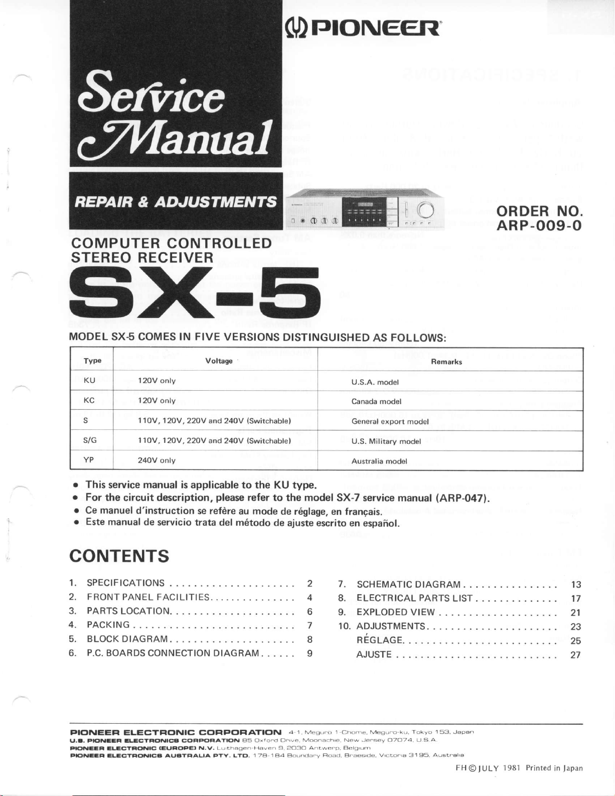
MODEL SX6 COMES IN FIVE
Typo VoltagE
KU 120V
KC 120V
s/G 1 1OV. 1 2OV,
YP
o
This
service
o
For the
r
Ce manuel
o
Este
circuit
manual de
only
only
'l1OV,
12OV,220V
22OV and 240V
24OV only
manual is
applicable to the KU type.
description,
d'instruction
servicio trata
VERSIONS
and 240V
please
se refdre
del m6todo
lswitchable)
(Switchable)
refer to
mode
au
DISTINGUISHED
U.S.A. model
Canada model
General export model
U.S. Military
Australia model
model
the
de r6glage,
SX-7 service manual
en frangais.
de aluste escrito en
AS FOLLOWS:
model
espaiol.
Rem.lks
(ARP-047).
ORDER
NO.
ARP-OO9-O
CONTENTS
SPECIFICATIONS
F
2.
RONT PANEL FACILITIES.
PARTS
PACKING
4.
BLOCK DIAGRAM
o.
P.C.
PIC'NEEFI ELECYFICTNIC CGIFIFGIFIATIC'N
U.a, tElNttal aLlctFo|llcl CC'FFG,FAYICTN
tlmlltF lLCTaC,itC a-t
FlollatEt
LOCATION.
BOARDS
aL-CTa|<tNlCa AUaYEALI^
CONNECTION DIAGRAM .
FC,FE| N.v. Lu'ihasen
aS oxro.d cj.
FYY. LYE ,
B3ver,
1 7A I
a 1. Mesu.o
ve. Mo
9,2O3O
Aa Bot,nd
2
4
o
I
ati.we.p
7.
SCHEMATIC
ELECTRICAL
8.
EXPLODED
9.
10. ADJUSTME
Ec
n
uce.
AJUSTE
Bergtr)m
70-24
tde'6 3195
DIAGRAM
PARTS
VIEW
NTS.
A
U S
Aust.ar6
LIST
FHO
IULY
l98l
Printed
in
13
21
23
25
27
lapan
1.
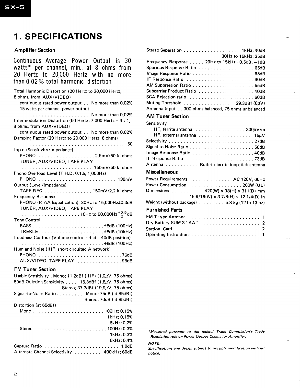
SPECIFICATIONS
Amplifier
Continuous
watts*
20 Hertz
than
Total Harmonic
ohms, from
8
continuous rated
15
ntermodulation
f
8 ohms,
continuous rated
Damping
put
I n
PHONO
TUNER, AUX/VIDEO,
Phono
PHONO
Output ( Level/l mpedance)
TAPE REC
Frequency
PHONO
TUNER,
Tone Control
BASS.
TREBLE
Loudness Contour
Hum and
PHONO
AUX/VIDEO,TAPEPLAY.
Section
Average Power
per
channel, min.,
20,000
to
0.02
watts
from
(Sensitivity/l
Overload Level
total
%
Distortion
AUX/VIDEO)
per
channel
Distortion
AUX/VIDEO)
(20
Factor
mpedance)
Response
(RIAA
Equalization)
AUX/VIDEO, TAPE
(Volume
(lHF,
Noise
harmonic
(2O
power
output
power
power
output .
Hertz
to 20,000
TAPE
(T.H.D.
short circuited A
0utput is
at 8 ohms from
Hertz with no
distortion.
Hertz to
output
(50
Hertz; 7,000 Hertz = 4 :
O.1%, 1,000H2)
. . . .
control set at
20,000
No
. .
No
No more
.
Hertz,
..2.5mV/50kilohms
PLAY
.15OmYl22
30Hz to 15,000H210.3d8
PLAY
1OHzto 50,000H21!'uoe
network)
Hertz,
more than
more than 0.027o
than 0.02%
8 ohms)
150mV/50 kilohms
..18d8(100H2)
.
.18d8
-4OdB
. .
position)
+6dB
. . .76d8
....96d8
30
more
0.02%
1,
50
130mV
kilohms
(10kHz)
(100H2)
StereoSeparation.
Frequency
SpuriousResponseRatio.
lmage
lF
Response
AM
SubcarrierProductRatio.
SCA
Muting
Antenna
AM
Sensitivity
lHF, ferrite
lHF,
Selectivity
Signal-to-NoiseRatio
lmage Response
lFResponseRatio.
Antenna
Flesponse
Response Ratio
Ratio
.
Suppression Ratio
Rejection
Threshold
Input
ratio
. . 300
Tuner Section
antenna
external
antenna
Ratio
2OHz
ohms
balanced, 75
Built-in ferrite loopstick
Miscellaneous
Power
Requirements
PowerConsumption
Dimensions
Weight
(without
Furnished
FM
T-type
DryBatterySUM-3"AA"
StationCard.
Operating Instructions
package)
Parts
Antenna
420(W) x
.
16-9/16(W)
.
lkHz;4OdB
...
30Hz to 15kHz;35dB
to l5kHz
x
3-7l8(H) x 12-114(Dl
. . . . 5.8 kS
+0.5d8,
. .
29.3dBf
ohms unbalanced
AC 120V,
...200W(UL)
98(H) x
-1dB
...65d8
.65dB
. .90d8
.
...40d8
. 60dB
(8pV)
. . 300pV/m
....27d8
..50d8
.
..73d8
antenna
311(D) mm
(12lb
13oz)
....2
......2
55dB
15pV
40dB
60Hz
in
1
1
FM
Tuner
Usable
50dB
Signal-to-Noise
Distortion
Mono.
Stereo
CaptureRatio.
AlternateChannelSelectivity
Section
Sensitivity .
Ouieting
Sensitivity
Ratio Mono;75d8
(at
65dBf)
Mono;
Stereo;
11.2dBf
16.3dBf
. . . .
37.zd9f
(lHF) (1.OpV,75
(1.8pV,
(19.9pV,
Stereo;70dB
...100H2;0.15%
....100H2;
.. ..
75
75 ohms)
(at
85dBf)
(at
85dBf)
lkHz:0.15o/o
6kHz:O.2o/o
lkHz;
6kHz:O.4o/o
....1.0dB
400kHz;60dB
ohms)
ohms)
0.3%
O.3o/o
*Measured
Regulation rule on Power Output Claims
NOTE:
Specifications
notice-
pursuant
to the
and design subject
federal
to
possible
Trade
for
Commission's
Amplifier.
modification
Trade
without
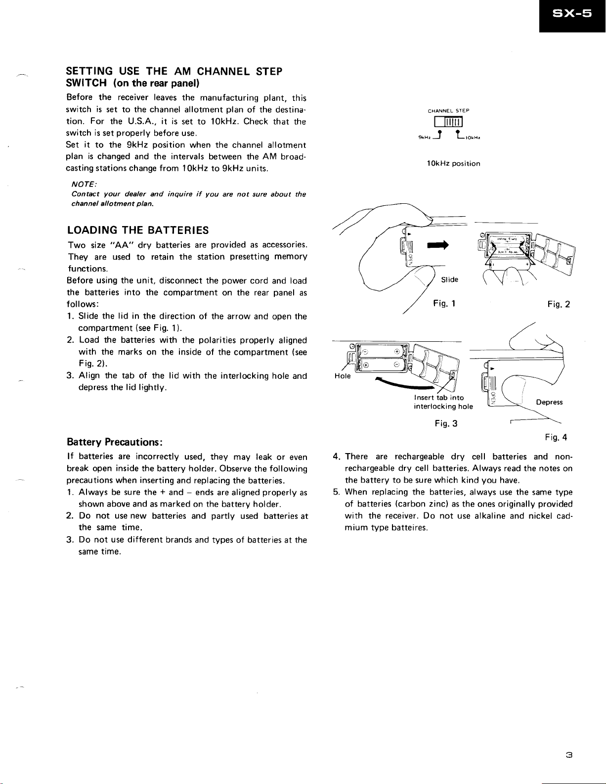
SETTING USE
SWITCH
Before the receiver leaves
switch
tion.
switch is set
Set
plan
casting
(on
is
set to the channel
For
the U.S.A.. it is
it
to the
is
changed and the intervals
stations change from 1
THE AM
the rear
properly
9kHz
CHANNEL STEP
panel)
the
manufacturing
allotment
set to 1OkHz. Check
before use.
position
when the channel allotment
OkHz
NOTE:
Contact
chan nel al
your
I
otment
dealer
pla
and
n.
inquire if
you
LOADING THE BATTERIES
Two size
They are
"AA"
used
to
dry batteries
retain the station
functions.
Before using the unit, disconnect
the batteries
into
the
compartment on the rear
follows:
1. Slide the
compartment
Load the batteries
2.
with the
Fis.
Align
3.
depress
lid in
(see
marks on the
2).
the tab
the lid lightly.
the direction
Fig.
with the
of the
are
the
of the arrow and
1).
polarities
inside
of the compartment
lid
with the interlocking
plan
of the destina-
between the
to
provided
units.
9kHz
are not sure about
as accessories.
presetting
power
cord
properly
plant,
that the
AM
broad-
memory
and
panel
oDen
aligned
hole and
this
the
load
as
the
(see
STEP
CHANNEL
iTil
f-Iil
??
l
OkHz
LtOrHz
position
9lHr J
Insert tab into
interlocking hole
Fis.2
Battery Precautions:
batteries
lf
break
precautions
Always
1.
shown
2. Do not
the same time.
Do
3.
same
are incorrectly
open inside
when inserting
sure
be
above and
new
use
not use
different
time.
the battery holder. Observe
the + and - ends
marked
as
batteries
used,
they may leak
replacing
and
are aligned
on the battery holder.
partly
and
brands
and types of batteries
or even
following
the
the batteries.
properly
used batteries
at
as
at
the
4.
There
rechargeable
the
When replacing
5.
of
with
are rechargeable
dry cell batteries. Always
battery
batteries
to be sure
(carbon
receiver. Do not
the
mium type batteires.
Fis.
3
dry cell batteries and non-
read the notes
kind
you
have.
which
the batteries, always use the
zinc)
as the ones originally
use alkaline and nickel cad-
Fis.4
type
same
provided
on
3
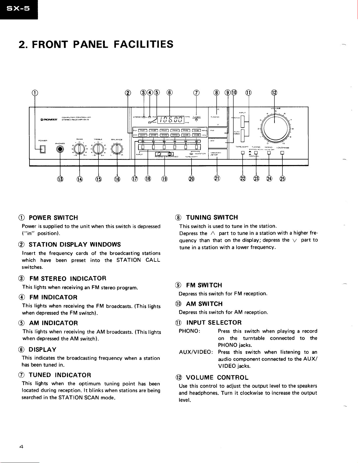
2. FRONT
PANEL
FACILITIES
{D|ffi
l\Ui
powen
O
Power
("in"
STETION DISPLAY WINDOWS
O
Insert
which have
switches.
FM
@
This lights
FM INDIcAToR
@
This
lights
when depressed
AM INDICATOR
O
This
lights when
when
DISPLAY
G)
This indicates
has
been tuned
TUNED
€)
This lights when
located
searched in the
swtrcH
is
supplied to the unit when this
position).
frequency
the
preset
been
STEREo INDICATOR
when receiving
when receiving
FM
the
receiving
depressed
during reception. lt
the AM
the
broadcasting frequency
in.
INDICATOR
the optimum
STATION
l\ri:
cards of the broadcasting
into
FM
an
FM
the
switch).
the AM broadcasts.
switch).
blinks when
SCAN
\+4
switch
STATION
the
program.
stereo
broadcasts.
when
tuning
mode.
point
stations are being
_-FFF.o_o
is depressed
(This
-)ll
_!E
./tttttt,uttl
T,-;r T:C] T-w-'l r;;-l r;Gt
stations
CALL
lights
(This
lights
a station
has
been
nnl*.
_#
r;E-l
TUNING SWITCH
@
This switch
Depress
quency
tune
FM SWITCH
@
Depress this
nm
@
Depress this
|NPUT SELECTOR
o
PHONO:
AUX/VIDEO:
voluruE
@
Use this
and headphones. Turn it
level.
is used to tune
part
A
the
that on the
than
in a station with a
switch for
swtrcH
switch for AM
Press
on the turntable
PHONO
Press
audio
VIDEO
coNTRoL
control
to adjust the output
in the station.
to tune
in a station
display; depress
lower frequency.
FM reception.
reception.
switch when
this
jacks.
this switch
component
jacks.
clockwise
connected to the
higher fre-
with a
part
the
V
playing
connected to the
when listening to an
level
to the speakers
to increase the
to
a record
AUX/
output
PHONES
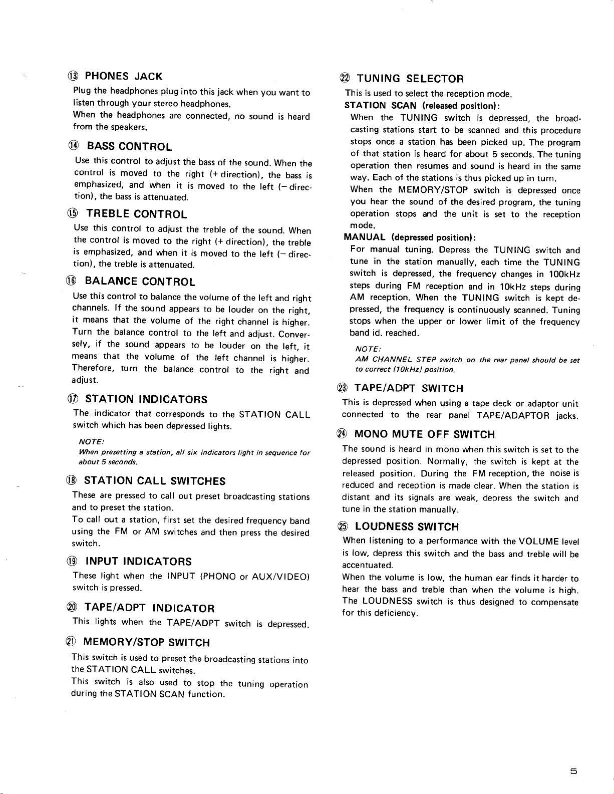
G)
Plug
the
headphones
listen
through
When
the headphones
from
the
speakers.
BAss
@
Use this
control
emphasized,
tion),
c)
Use
the
is
tion), the
@
Use this
channels. lf
it
Turn
sely, if
means
Therefore,
adjust.
@
The
switch which
NOTE:
When
about 5 seconds.
@
These
and to
To
using the
switch.
@
These
switch is
@
This
control
is
the
bass
TREBLE
this
control
control
emphasized,
treble
BALANCE
control
means
that
the balance
the
that
srnrroN
indicator
presetting
srRrIoN
pressed
are
preset
call
out a station,
FM
|NPUT
light
oressed.
TAPE/ADPT
lights
JACK
plug
into
your
stereo headphones.
are
connected,
coNTRoL
to
adjust
the
moved
to
and
when
is
attenuated.
the right
it
is moved
CONTROL
to
adjust
the
is
moved
the
sound
the volume
turn
to
the right
and when
is
attenuated.
CONTROL
to
balance
sound
appears
the
volume
control
appears
the
balance
it is
the volume
of the
to the
to be louder
of
tNDtcATORS
that corresponds
has
been
depressed
a
cALL
the station.
AM
or
TNDTCATORS
when
when
all
station,
six indicators light
SWITcHES
to
call
out
first
set the desired
switches
INPUT
the
|ND|CATOR
the
TAPE/ADPT
jack
this
bass
of the
(+
direction),
to
treble
of the
(+
direction),
moved
to
be louder
right
left
and
the
left
control
to the
lights.
preset
broadcasting
and then
(PHONO
switch
you
when
no
sound is heard
sound.
the
the
left
sound.
to
the left
of
the left
on
channel
adjust.
on the left,
channel
to
the
STATION
in
sequence
frequency
press
the desired
AUX/VtDEO)
or
is depressed.
wanr
to
When
the
bass is
(-
direc_
When
the
treble
(-
direc-
and right
the
right,
is higher.
Conver-
is
higher.
right
and
CALL
for
stations
band
rururruc
@
This
is used
STATION
When
casting stations
stops once
of
that station
operation
way.
Each
When
you
hear
operation
mode.
MANUAL
For
manual
tune
in
switch
steps during
reception.
AM
pressed,
stops when
band id. reached.
it
NOTE:
,AM
CHANNEL
to correct
rape/aDPT
@
This is
connected
@
The
depressed
reduced and reception
distant and its
tune
@
accentuated.
When
The
for
depressed
uoruo
sound is heard
released
in
the
LOUDNESS
When
listening
is
low,
depress
the volume
hear
the
LOUDNESS
this
deficiency.
sELEcroR
to
select the reception
SCAN
the
the MEMORY/STOP
the sound
(depressed
the station
is depressed,
the frequency
(released
TUNING
start to be scanned
a station has
is heard for
then
resumes
of the
stations is
stops
and the unit
tuning.
FM reception
When
the upper
STEP
(lOkHz)
position.
swtrcH
when
to
the rear
MUTE
position.
position.
station
bass
oFF
in mono
Normally,
During
signals
manually.
SWTTCH
performance
to a
this switch
is low,
and treble
switch
position):
switch is depressed,
been
about
and
thus
of the
desired
position):
Depress the
manually,
the frequency
and
the
TUNING
is continuously
or lower limit
switch on
using
a tape deck
panel
SWITcH
when
the FM
is
made
are weak,
and the bass
the human
than when
is
thus
mode.
the broad-
and
this
picked
sound is
switch
each time
the
TAPE/ADAPTOR
the
clear.
with
designed
up.
The
5 seconds. The tuning
heard
in the
picked
up
in turn.
is
depressed once
program,
is
set to the reception
TUNING
changes
in lOkHz
switch is kept
rear
this
switch is set
switch is kept
reception, the
When
depress
the VOLUME
ear
the volume
switch
the
in 100kHz
steps
scanned.
of
the
panet
should be
or adaptor
the station is
the
switch and
and treble will
f inds
it harder
to compensate
procedure
program
same
the tuning
and
TUNING
during
de-
Tuning
frequency
set
unit
jacks.
to the
at the
noise is
level
be
to
is high.
meuonY/srop
@
This
switch
is
used
the
STATION
This
switch
during
the
CALL
is
also
STATION
swtrcH
preset
to
switches.
used
SCAN
the
broadcasting
to
stop
function.
the
stations
tuning
into
operation
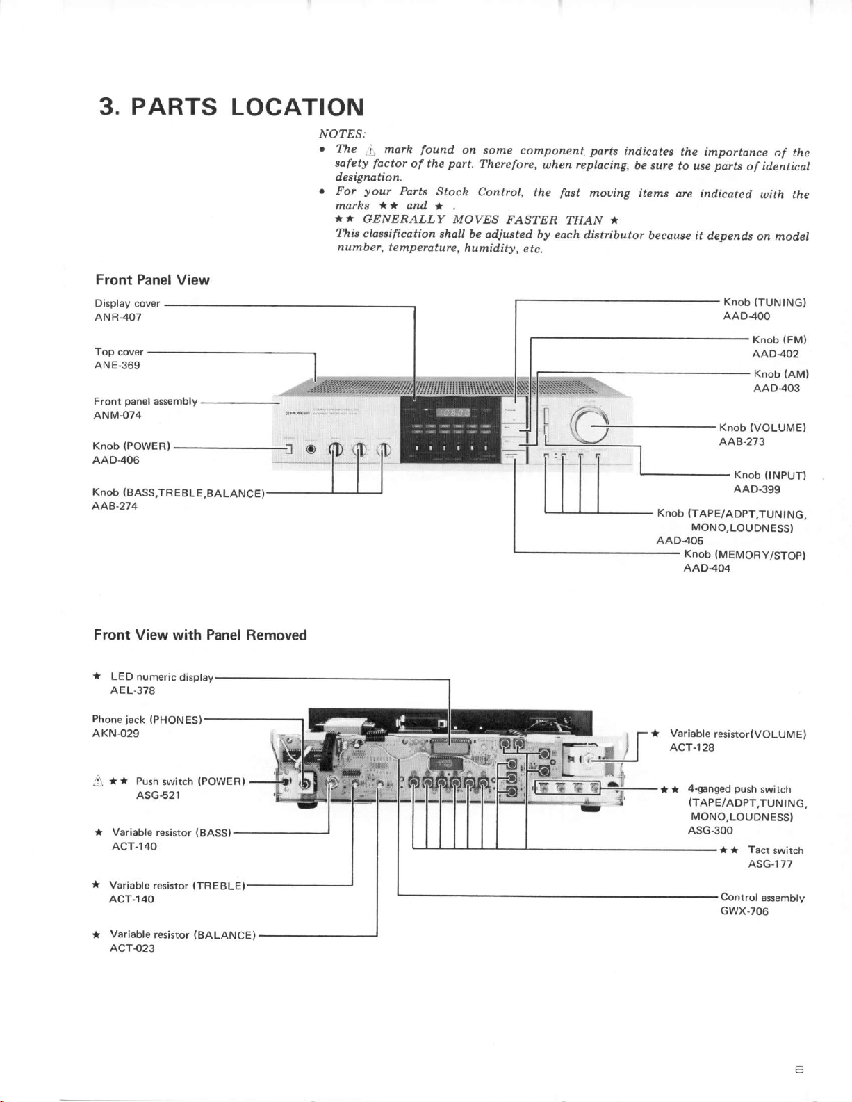
PARTS
3.
LOCATION
NO?ES:
The
sofety
deeignotio n,
your
For
marhs
A'
GENERALLY
Thia
cloeaificotion eholl
n umber,
marh
,i.
foctor
of the
Pafis
*)
and *
te mpe roturc,
found
Stoch
on some
port,
Therefore,
Controt,
MOVES
be adjusted
h umidity,
component
uhen
the
FASTER
by each
e tc.
pdrts
rcplocing,
mouing
fast
THAN
disttibutor
indicates
be sure to use
items
orc indicated
*
because it depends
the
importance
parts
of the
of identicdt
raith
the
on
model
Front Panel
Display
cover
ANR4O7
Top cover
ANE.369
panel
Front
ANM.O74
Knob
AAD406
Knob
AAB.274
Front
rt
LED
AEL.378
assembly
(POWER)
(BASSJREBLE
View with Panel Removed
numeric
View
-
---------------
Knob
ITUNING)
AAD4OO
(FMl
Knob
AAD4O2
(AM)
Knob
AAD403
(VOLUMEI
Knob
tD
f
Knob
AAD405
AAB'273
Knob
{INPUT}
AAD-399
ITAPE/ADPT,TUNtNG,
MONO,LOUDNESS)
(MEMORY/STOP)
Knob
AAD.4O4
jack
Phone
AKN{29
t t Push
A
Variable
ACT-140
Variable
ACT-140
Variabte
ACT-023
(PHONESI
swirch
ASG-521
resistor
resistor
resistor
IPOWER)
(BASS)
(BALANCE)
Variable
ACT-128
I
*
resistor(VOLUME)
4-ganged
(TAPE/ADPT,TUNING,
MONO,LOUDNESSI
ASG-300
push
tt * Tact
ASG-177
Controlassembly
GWX-706
switch
switch
6
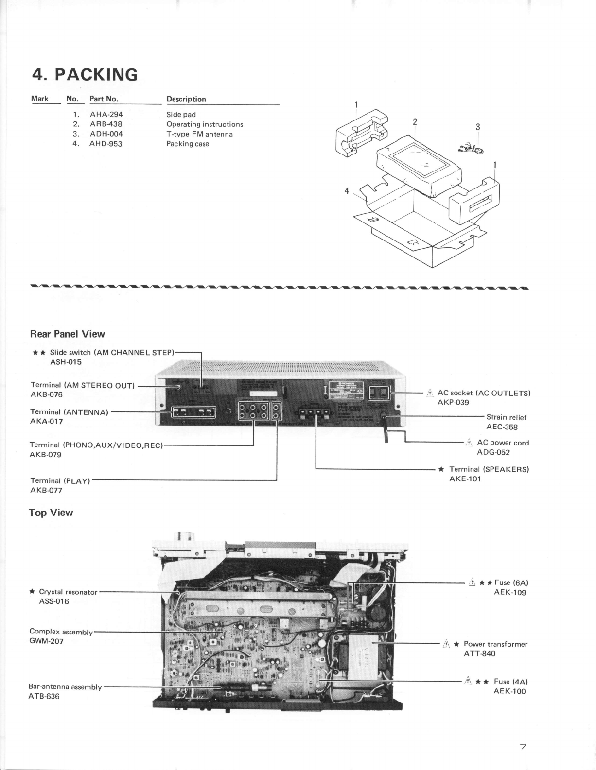
4.
PACKING
Mark
Rear
*
No.
Panel
* Slide switch
ASH-O15
Part
No.
AHA-294
1.
2. AR8438
3. ADH-004
4.
AHD-953
View
(AM
CHANNEL STEP!
Description
pad
Side
Operating instructions
FM
T-type
Packing
antenna
case
Terminal
AKB076
Terminal
AKAO17
Terminat
AKB-079
Terminal
AK8077
View
Top
Crystal
ASS-016
Complex
GWM.2O7
(AM
STEREO
(ANTENNA)
(PHoNo,AUX/Vt
(PLAY)
resonator
assembly
OUT)
DEO,REC)
AC
socket
,.r
AKP-039
* Terminal
AKE-10'l
.A*
(AC
OUTLETSI
Strain
AEC-358
power
AC
ADG.O52
(SPEAKERSI
A*tFuse(64)
AEK.l09
Power
transformer
ATT€40
relief
cord
Bar€ntenna
ATB-636
assembly
A**
Fuse(eel
AEK.lOO
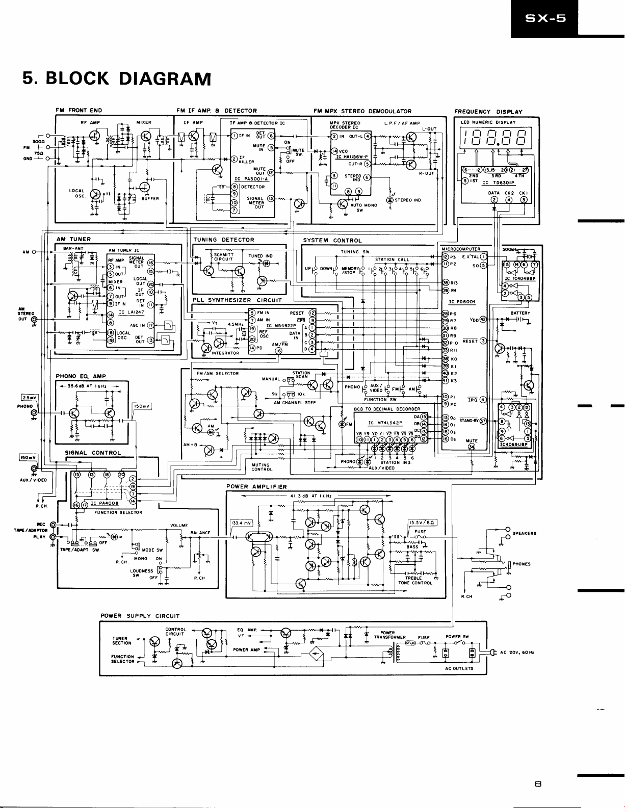
BLOCK
5.
FT
T_
loon
FTF
730
cxo!
FRONT
DIAGRAM
ENO
FM
IF
AMP
A DETECTOR
IF AMP
I
I
I
I
A
OETECTOR IC
osrecroa
sronau
rrET€R
our
FM
MPX
MPX
OECOOER
STEREO
STEREO
IC
DEMOOULATOR
L.P,F / AF AMP
FREQUENCY
ITUTERIC
LEO
,L-'L-'DN
t_t l_t
I
oaTA cK2
DISPLAY
OISPLIY
.l_t
l_t
Cr(l
-
lur / vroEo
lgzlxtrro'-
t.
ifc
'LIY
cx
AT TUNER
8 R-Axr..
PHONO
EO.
t*
.n r_#@*
._.op_q
TAPE,/ADrpr
-
AMP.
FUIICTIOT
oFF
sw
Ar rurER
SELECTOR
f
R.
CX.
LOUDNESS
rc
S
"o*o
sw
xooe
oFF
TUNING
OETECTOR
E, X'TAL
P3
P2
so
Rr3
PLL
SYNTHESIZER
POWER
CIRCUIT
FM IN
AM
MUT
ING
CONTR OL
AMPLIFIER
RESET
CHANNEL STEP
4l.3dB AT lltlr
IC M74LS42P
Y8
Y9 YO YI Y2 Y3 Y4 Y!
r2
34 5 6
STATION
IilD.
r5.5
V / 8II
R4
IC
to
P06004
RESEr
srer*ens
sw
oN
G
f1--=Lu
| .+
l-H
-"'----------v
--s-------*---\H
,<5
-O
fl
)r
PHoxEs
-
POWER
SUPPLY
CIRCUIT
CONTROL
crRcurr
AC
OUTL ETS
AC l2OV,
50 Xr
-
a
E
1
I
t2l
il
3
A
B
6.P
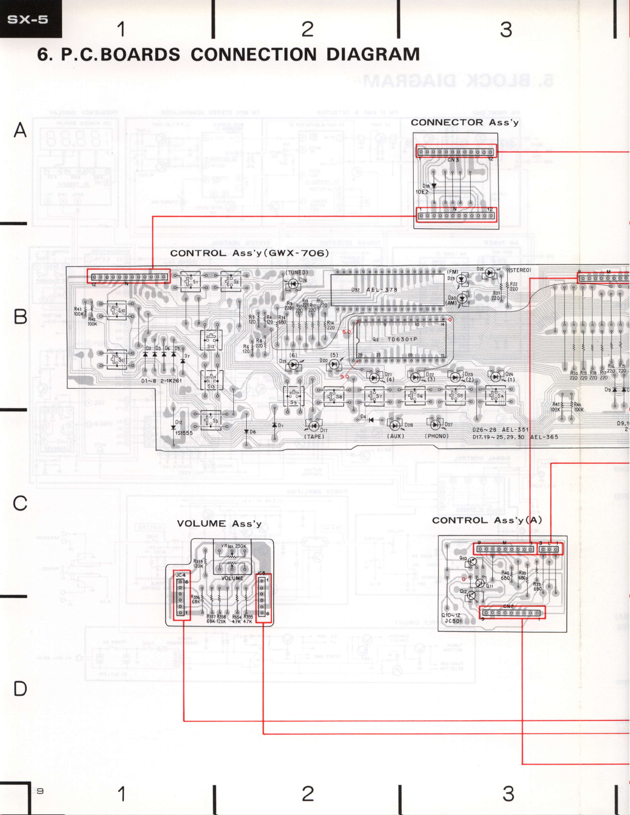
.C.
BOARDS
CONNECTION
DIAGRAM
C
D
-1
",'1
 Loading...