

Pioneer SX-303 Service manual

(D
rrloNEEFl'
:-_
t
I
I
AM/FM
STEREO
RECETVER
sixr3Gl3
MODEL
Model
sx-303/KU
sx-303/Kc
sx-303/s
SX-303L/HE
sx-303L/HEZ
o
This
service manual
additional
o
manuel
Ge
o
Este
manual
SX-303
(SX-303L)
AC120V only
AC120V only
AC1 1 0V,
AC220V
AC220V
'l2OV
only
only
is
service
manual.
d'instruction
de
servicio
COMES
Voltage
,22OV
applicable
se refdre
IN FIVE
and
24OV
to the
au mode
trata del m6todo
VERSIONS
(switchabte)
KU types.
de r6glage,
de
ajuste
For
servicing
en frangais.
escrito
en espafiol.
DISTINGUISHED
U.S.A. model
Canada model
General export
European
West
continent
germany
of the
AS FOLLOWS:
Remarks
model
model
model
with AM-LW
other types,
ORDER
ARP-
with AM-LW
band tuner
please
232-0
band tuner
refer
NO.
to the
CONTENTS
1.
SPECIFICATIONS
2.
FRONT
3.
PARTS
4.
BLOCK
5,
CIRCUIT
PACKING
6.
EXPLODED
7.
PICINEEFI
FIC|NEEFI
FfoNEEFI
PI('NEEFf
PANEL
LOCATION
DIAGRAM
ELECTFICINI€9
ELEcrFloNlc
ELECTFICINIGB
FACILITIES
DESCRIPTIONS
VIEW
AND PARTS
ELECTFICINIC
.
IUAAI
[EuFtoPEI
AUaTFIALIA
LIST
CclFlPClFIATIClN
lNC. 1925
N.v.
E.
Keerbengtean
FTY.
Dorninguez
t-lO.
lzA-le4
2
3
4
5
6
8
9
4-1,
St., Long
1,e74o
Boundany Ftoad,
8. P.C.
9.
10.
11. DIALCORDSTRINGING
12.
BOARDS
SCHEMATIC DIAGRAM
ELECTRICAL
ADJUSTMENTS...
CONNECTION
PARTS
LIST
DIAGRAM
. .
nEcucr
AJUSTE
Meguno
Bevenen,
1-chome,
Beech,
Catifonnia
Betgium
Bnaeside,
Mesuno-ku,
gOB1O
Victonier
YX O DEC.
Tokyo
U.S.A.
819F,
1F3,
1982
Japan
.Ausrnatia
Printed
......
... 24
in
lapan
12
15
17
19
20
22
1.
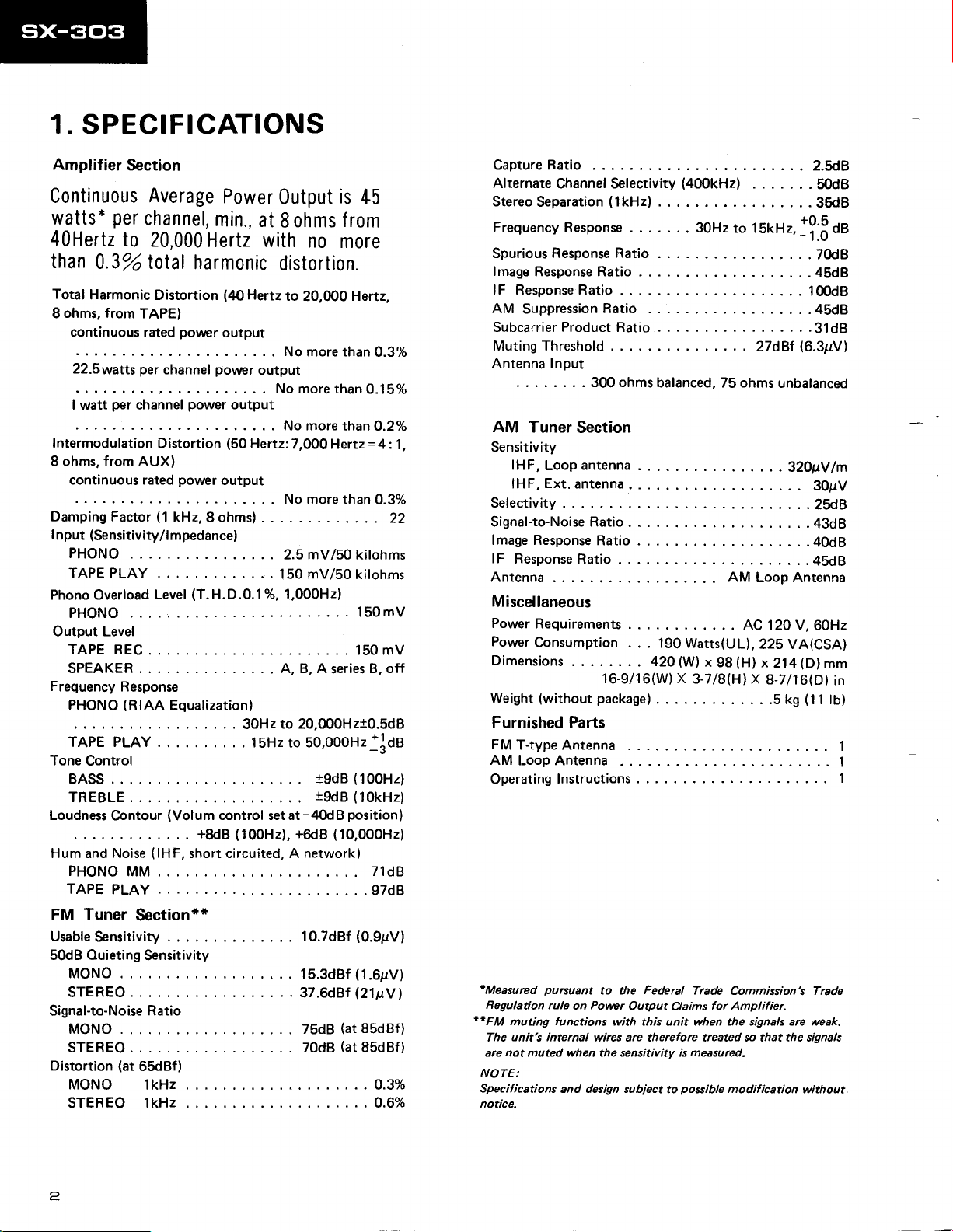
SPECIFICATIONS
Amplifier
Continuous
watts*
40Hertz
than
Total
ohms, from
I
continuous rated
22.5watts
I watt
Section
Average
per
channel,
to
20,000
0.3o/o total
Harmonic
per
Distortion
TAPE)
povrrcr
per
channel
channel
Power
min.,
Output
at
Hertz with
harmonic
(40
output
power
power
output
distortion.
Hertz
output
. . . . No more than
is
45
ohms f rom
8
no
more
to
20,fi)0
No more than
Hertz,
0.3%
O.15yo
l*"r..irr"ii""oiri.r,i""it,i""r,rlrt,ill'iJir1"=t;?1,
from
ohms,
8
continuous rated
Damping Factor
(Sensitivity/l
I
nput
PHONO
TAPE
Phono
PHONO
Output Level
TAPE REC
SPEAKER A, B, A
Frequency
PHONO
TAPE PLAY
Tone
Control
BASS
TREBLE
Loudness
Hum and
PHONO
TAPEPLAY
Tuner
FM
UsableSensitivity..
50dB Ouieting
MONO
STEREO
Signal-to-Noise
MONO
STEREO . . 70dB
Distortion
MONO
STEREO lkHz. ...O.6Yo
AUX)
PLAY
Overload
Level
Response
(RIAA
.
Contour
(lHF,
Noise
MM ..
Section**
Sensitivity
Ratio
(at
65dBf)
lkHz.
power
output
(1
kHz, 8 ohms)
mpedance)
(T.H.D.0.1%.
Equalization)
(Volum
control
+8dB
. .
short circuited, A
more
No
.....2.smV/S0kilohms
. . .
150
1,000H2)
.
to
30Hz
15Hz to SO,OOOHz+]OA
setat-40d8
(100H2),
+6dB
.10.7d8f(O.9pV)
...15.3dBf
..37.6d8f
...75d8(at85dBf)
than
0.3%
22
mV/50
20,000H2t0.5d8
network)
kilohms
. . 150mV
. 150 mV
B, off
series
(100H2)
i9dB
(10kHz)
19dB
position)
(10,000H2)
71dB
......97d8
(1.6pV)
(211ty1
(at
85dBf)
...0.3Yo
AMI-oopAntenna
Operating
'Measured
Regulation
**FM
The
are not muted when the sensitivity is measured.
NOTE:
Specifications
notice.
CaptureRatio .
Alternate
Stereo
Frequency Response
SpuriousResponseRatio.
lmageResponseRatio
lF ResponseRatio.
AMSuppressionRatio
SubcarrierProductRatio.
Muting Threshold
Antenna Input
AM
Sensitivity
Selectivity
Signal-to-Noise Ratio
lmage Response
lF
Antenna AM
Miscellaneous
Power
Power
Dimensions
Weight
Channel Selectivity
Separation
Tuner
f HF,
Loop
Ext.
lHF,
ResponseRatio.
Requirements
Consumption .
(without
(lkHz)
. . . 300 ohms
Section
antenna
antenna
Ratio
. . . 42O
16-9/16(W) X
package)
(400kHzl
..
30Hzto lSkHz,1ffOt
balanced, 75 ohms
AC
.
. . 190 Watts(UL),
(W)
x
98
lHl
3-718(H)
Furnished Parts
FMT-typeAntenna
Instructions
pursuant
rule
functions
muting
unit's internal
and design subject
Povver
on
wires are therefore treated so that the signals
Federal
to the
Output
with this unit when the signals are weak.
Claims
possible
to
Trade
Commission's Trade
for
Amplifier.
modification
..2.5d8
. .
50dB
. .
35dB
......7ft8
....45d8
....100d8
...45d8
......31d8
(6.3pV)
27dBf
unbalanced
32O1N
30gV
.
2ft8
. . . ..43d8
....40d8
.....45d8
Loop Antenna
120 V,
60Hz
22S VA(CSA)
(D)
x
214
X
8-7116(D)
. .5 kS
........1
mm
(11
......1
without
lm
in
tO)
1
2

2.
FRONT
PANEL FACILITIES
powen
O
Push
this to
supplied at the
turned
off at the released
HenopHoNE
@
Connect the
when listening to
rorue
@
BASS
TREBLE
eeLeNcE
@
This
is normally
when
the volume
right
channels of
The right
rotatd
the left
toward
@
PHONO :
FM : Press
AM :
@
This
connected
o
Depress
sound at a low level
and treble
volume.
the RIGHT.
rurucrroN
rape
is depressed
LouorrrEss
swrrcH
wrritch
depressed
plug
on the stereo headphones
sound through
coNTRoLs
:
Thebass
clockwise from the
when rotated
:
The treble is increased
rotated
reduced
channel volume is reduced
toward
channel
clockwise
when rotated
coNTRoL
kept at its center
of
the speakers or
the LEFT
volume
swrrcHEs
Press when listening
when listening to FM
Press when listening
(ADPT)
when using a tape
rear
to the
this
svrritch to the
give
and
on
and off
(r)
(I)
the
switch
position
unit's
position
(OFF).
power.
(ON)
JAcK
to this
headphones.
is increased
sound delivered through the left
whenthiscontrol
position
center
counterclockwise.
when
from
the center
counterclockwise.
position.
headphones
when the control is
from
the
center
is reduced
to records.
to AM broadcasts.
when it is rotated
broadcasts.
isrotated
and reduced
this
control is
position
lt is
differs.
position
swrrcH
or
panel
TAPE/ADAPTOR
deck
adaptor
jacks.
swtTcH
position
ON
of volume. This
more life
to the sound
when listening to
enhance the bass
will
even at a low
Power
and
jack
and
rotated
and
while
unit
voluruE
@
is
Use this to
through
The
clockwise from
@
This lights up
tuned in.
@
This lights up
casting in
@
These are used to
will listen
The selected
A: The
B: The
No sound
are both released.
can
and B
@
This indicates
(FM,
The
The
@
Rotate this knob
@
the
volume
ruruIruG
sreneo rNDrcAToR
stereo
speerERs
to the sound.
sound
the
speaker
sound is heard
the
speaker B terminals
heard
be
NOTE:
No
rcund will
switches are depressed
connected
FREoUENcY
AM).
level figures
top
bottom level
TUNTNG
POWER
coNTRoL
adjust the volume
speakers or headphones.
is
increased
the minimum
when this
"0"
tNDIcAToR
to indicate
automatically when
has been
that
an
tuned in.
swrrcHEs
the
select
speakers are now working.
is heard from
A terminals on the rear
heard
will be
This is the
through
to either
the headphones.
heard
be
the A or
frequency
the
(88
figures
KNoB
pick
to
|ND|CATOR
speakers through which
the speakers connected to
from
the speakers connected to
on the rear
when
SPEAKERS
position
through
the spakers when
if
only one
I SPEAKE RS terminals.
scALE
of the broadcasting
-
108)
-
(55
160)
up
stations
of
the
sound delivered
control
position.
(TUNING)
FM,
AM station has
(srEREo)
FM
an
indicate
indicate
(FM,
station broad-
panel.
panel.
A and B switches
at which the sound
set of speakers has
the FM band.
the AM band.
AM).
is rotated
been
you
both
the
been
station
A
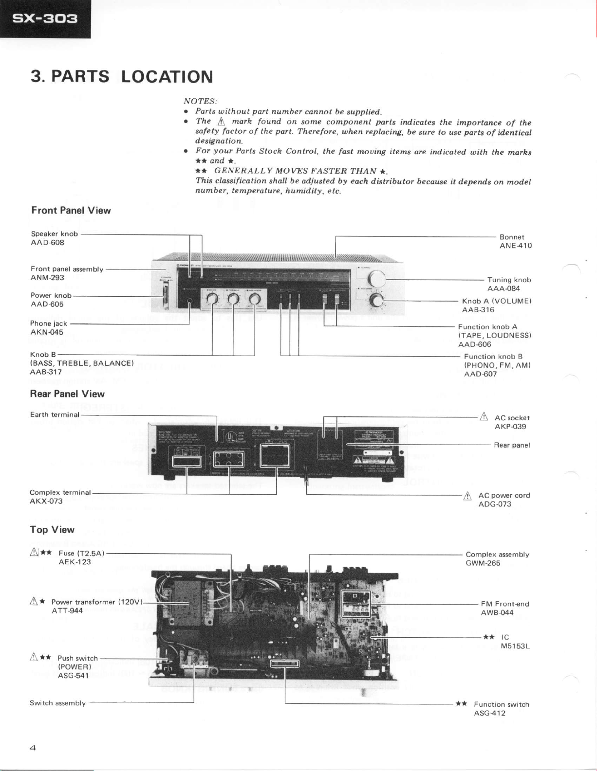
PARTS
3.
LOCATION
NOTES:
.
Parts
.
The b morh
sofety
designation.
.
your
For
ta
and
''
GENERALLY
Thb claesificotion
numbe
l.
part
found
of
the
Potts
Stock Control, the
without
factor
f , te mperature,
nu
ber connot be
on
aome component
port-
Thereforc,
MOWS FASTER
be
shall
odjusted by eoch di;tributor
humidity, e tc.
supplied.
ports
uhen replocing,
fost
THAN '.
mot)ing
items are
indicates
be
6ure
becouse
the importonce
ports
to
use
indicated u)ith
it deDends
of the
of id.enticol
the moths
on model
Front Panel
Speaker knob
AAD60A
panel
Front
ANM-293
AAD$O5
jack
Phone
AKN-(X5
Knob B
(BASS,
TREBLE, BALANCE)
AAB3I7
View
assembly
Rear Panel View
Earth
terminal
Complex terminal
AKX{73
..-":.n
f\,-
Bonnet
ANE4lO
Knob A
AAB316
Function knob A
{TAPE,
AAD€06
(vo
LU1M E)
LOUDNESS)
Function knob B
(PHONO,
AAD607
FM,
A ac socket
AKP.O39
AM)
Top View
(T2.5A)
Fuse
l\r*t
AEK-123
Push swirch
A**
(POWER'
ASG-541
Switch assembly
AWB{44
**
tc
M5153L

BLOCK DIAGRAM
4.
T
3OOO
|
.
FM
I
L r rrupar
l-
AM
LOOP
I
L
BAL
cND
ANT
AM
FM
FRONT
FRONT
ENO
END
FM(Rch)
(1/3)
rcr
r-;1-l
i
Itfr
(Lch)
FM
lrJ
i
I
MIX AMP
LED
DRIVER FM
FM.IF AMP
MUTE
+82
AM
AM
04
IF
FT.I IF,/OET MPX
RE6ULA.
rfrR
METER
OETECTOR
AMP
tx
crav
l-
Lch REC
,"o"o
i-
eiror,ro
f
Rch
REC
".o"
l-
ac
r20v
60
Hr
[5dtl
lzsmrl
EQUALIZER AMP
sr-l
PHONO
r_-
134,4/41
sr-4
sr-5
TAPE
LO
(t/4)
lt/2) |
POWER SUPPLY A PROTECTOR
(t/?
sr-4
| 2/2 t
U ON ESS
)
sr-5
(2/2
(?/2)
)
POWER
ON,/OFF MUTING
ffi--D"t
TONE CONTROL
vR2-2,2-3
o='""o'
POWER AMP
s2-2
+92
SP- B
15.4V
07
(vzl
s2-l
SP-A
lt/2)
(
t'Ery I
pHoNEs
TO
Rch
SPEAKE RS
l
I"o
],,
^
: FUt{CTION
SI-l
SI-2: FUNCTION
sr-5 : FUt{cTroN ( AM)
:
TAPE MONITOR
SI-4
(PHOtlO)
{FM)
sr-5: LouoNEss
9!L-
oN
oN
ON
or
oFF
-.9!E
-.g_Eq
--qEE
-_q!!
S2.I : SPEAKERS
S2.2: SPEAXERS
-
oFF
_9_l!-
-
!-!L
oFF
I
sror
i
PoWER
oil - oFF
5

CIRCUIT DESCRIPTIONS
5.
FM Front End
A unitized variable capacitor
unit is used consisting of an
type front end
FET
single stage
RF
amp, local oscillator/mixer IC and an IF transformer.
FM
lF Amp,
2-transistor IF amp with
A
and the next
ing the FM IF detdctor and
diagram
IC uses
adjusted with a single
employed to
for
the
The IF signal
output is obtained
put passes
passes
signals
addition,
Detector and MPX Circuit
ceramic filter is used
stage
has an IC
(M51533L)
MPX circuit. The block
of IC M51533L is shown
peak
a
detection method
coil. The
reconstitute the 38kHz sub-carrier
MPX
circuit.
is input
through
through
the MPX circuit and
are obtained
from
the muting
at
pin
frorn
pin
5. The detection out-
pins
this unit detects the
in Fig. 5-1.
which can be
PLL
method
1 and the
goes
Q4,
the
11 and 1'2. In
presence
or absence
contain-
This
detection
pin
to
9,
stereo
pilot
of a
stereo
nected
pin
13
indicator.
and FM IF
FM Muting
With
when
antenna input
drops,
is
result,
off
and the detector
(Fig.
in,
the base
on and the
signal
to automatically
and mono reception
pin
to
drops to
14.
the low level
When
pin
operation
When a
2
is
stop
and LED Driver
this unit,
the antenna
muting is
input drops
decreases,
is turned
Q5
the
gate
off
voltage
and
of
output
5-1).
When
potential
an
FM
of
tuning indicator
switch between
by
R14 which is
stereo signal is received,
to light
grounded,
(for
AM).
automatically
below
the
voltage at
is turned
Q6
drops,
Q4
circuit is
or
AM station
is raised,
Q5
the stereo
PLL
the
VCO
activated
10pV. As the
pin
on.
As a
is turned
Q4
blocked
is tuned
is
turned
Q5
lights.
con-
3
OETECTOR
LEVE L
METE R
CIRCUIT
Fig.5-1
nrtr F?? |
INPUT
BU FFER
TER
S
EO
rTC
H
5W
R OUT
I
L OUT
FM lF,
Detector and
MPX
circuit
AM Tuner
This uses a
circuit
composed
sistor front
detector.
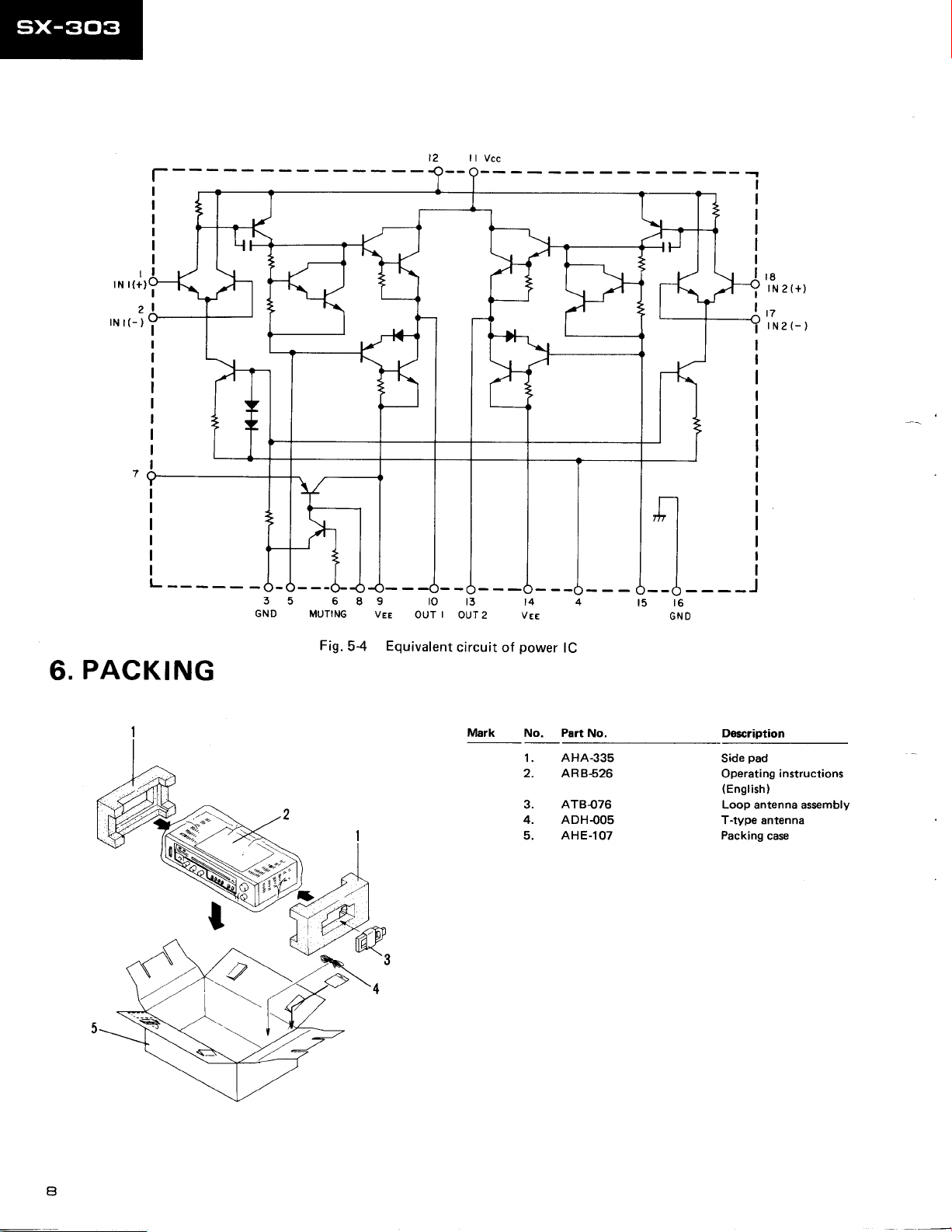
AF Section
The equalizer
(2
amp
The
channel)
power
STK4141-2S
The tone
feedback
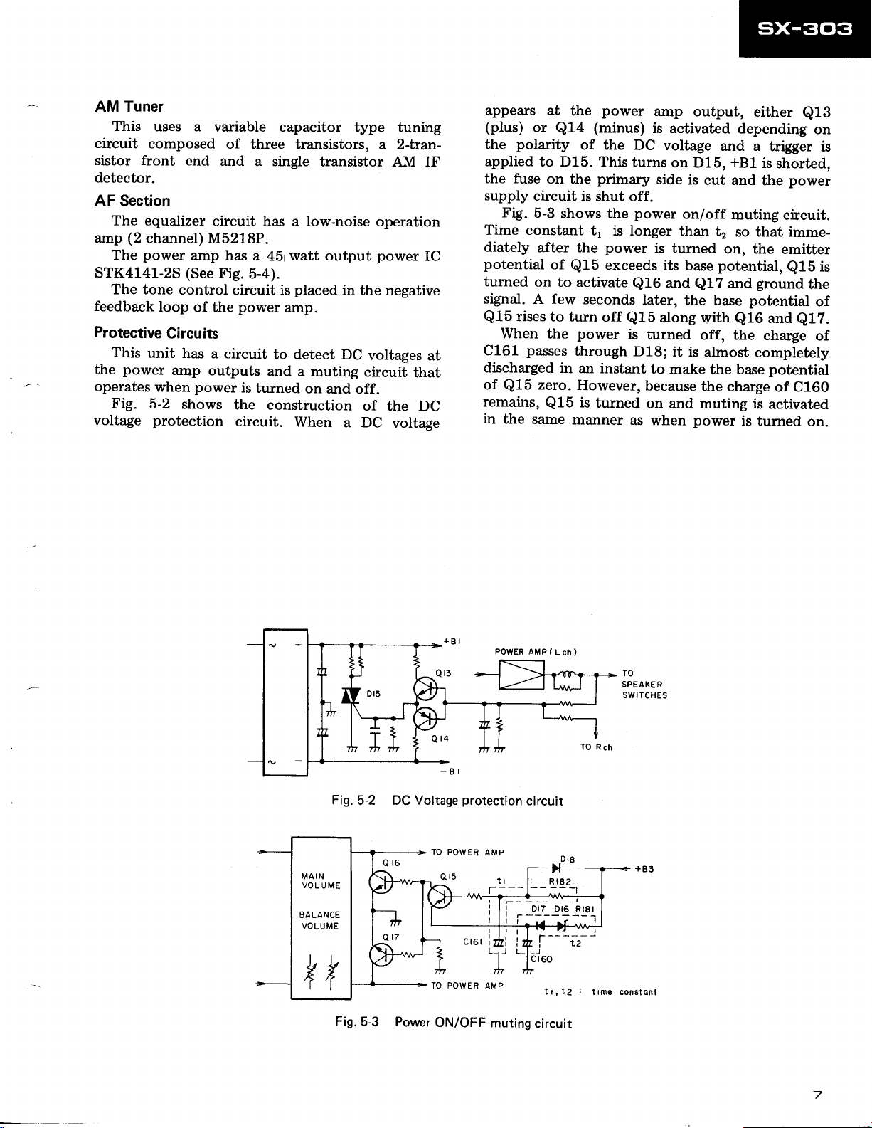
Protective
This
the
operates
Fig.
voltage
unit
power
when
5-2
protection
loop
Circuits
amp
variable capacitor
end
of three
and
transistors, a
a single
circuit has a low-noise
M5218P.
amp has
(See
control
of the
has a
outputs
power
shows
a
Fig.
5-4).
circuit is
power
circuit
is
turned
the
circuit.
watt output
45
placed
amp.
to
detect DC
and
construction
When
type tuning
transistor AM
in the negative
voltages
a
muting circuit
on and
off.
of
a DC
2-fuan-
IF
operation
power
IC
that
the DC
voltage
at
appears
(plus)
the
applied
the fuse
supply
Fig.
at
or
Q14
polarity
to D15.
on
circuit
5-3
the
the
shows
Time constant
diately
potential
turned
signal.
Q15
C161
discharged
of
remains,
in
after the
of
on to activate
A few
rises
to turn
When
the
passes
zero.
Q15
Q15
the
same
Q15
in
power
(minus)
of the
This
primary
is shut
the
t1 is longer
power
exceeds
seconds
off
power
through
an
instant
However,
is
turned
manner
amp
is activated
DC voltage
turns
on D15,
side
is
off.
power
on/off
than
is
turned
its base
and
Q16
later,
the base
along
Q15
is
turned
D18;
it is
to
make the
because
on
and
as when
output,
depending
and a
+81
cut and
muting
t2
so that imme-
on, the
potential,
and
Q17
with
Q16
off, the
almost
base
the
charge
muting is
power
is
either
Q13
trigger
is
shorted,
power
the
circuit.
emitter
Q15
ground
potential
and
e1Z.
charge
completely
potential
of C160
activated
turned
on.
on
is
is
the
of
of
Fig.
5-2
Fig. 5-3
Voltage
DC
Power
POWER AMP
protection
TO POWER AMP
ON/OFF
muting
(
L
circuit
tr,r2
circuit
ch )
TO
SPEAKE
R
SWITCHES
ont
const
I
rN r(+)l
2
rN
l(-
)
fi
r8
tN2(+)
t7
rN2(-)
I
I
PACKING
6.
GND
68
MUTING
Fis.5-4
9
VEE
to
OUT
Equivalent
ta
I
OUT 2
circuit
Mark No. Part
power
of
1.
2.
3.
4.
5.
.J
t6
GN
lC
No. Doscription
AHA.335
AR8526
ATB{76
ADH.OOS
AHE-107
pad
Side
Operating
(English
Loop antenna assembly
T-type antenna
Packing
instructions
)
case
a

T.EXPLODED VIEW
AND
PARTS
LIST
Mark
A
A
No. Part
1.
2.
*
3.
4.
5, AAD€O8 Speaker
6.
7.
8. AAB-317
9.
10. AAAO84 Tuning knob
11. A48-316 Knob A
12.
13. AAD€07
14. AAD€06
**
ts. ASG-541
16. AAD€05 Power knob
17. AEC-784
18. AXA-373 Tuning
19. AEC471 Nylon rivet
20.
No.
ANE410
BBZ30P080FZK
ATT-944 Power
PMZ30PO60FMC
VMZ30P06OFMC
NK9OFUC
NKT0FUC Nut
ANM-293
MTZ3OPIOOFZK
Description
Bonnet
Screw
Screw
Screw(3x6)
Nut
Knob
BALANCE}
Front
Function
FM,
Function
LOUDNESS}
Pushswitch
Cabinet
Screw
NO?ES:
o
Parts without
o
The
S
safety
designotion.
your
o
For
t* ond
*T GENERALLY
This classification shall
number,
(3
x
8)
transformer
(3
x
6l
knob
B
{BASS,
(VOLUME)
panel
assembly
knob B
AM)
knob A
(POWER)
bumper
shaft
(3
x
1O)
part
marh
of the
factor
Parts
*.
temperaturc,
{120V}
TREBLE,
(PHONO,
(TAPE.
found
number cannot
on
some
part.
Therefore, when
Stoch Control,
MOWS
TASTER THAN ).
be
adjusted
humidity, e tc.
lVlark
be
supplied.
component
the
mouing items are indicated with the morhs
fast
each
by
No. Part
50.
51 .
52.
53.
54.
55.
56.
57.
58.
59.
60.
61.
62.
63.
64.
65.
66.
67.
68.
69.
parts
replacing,
indicates the importance
be
sure
distributor because it depends on model
No. Decriptions
parts
to use
Speaker switch assembly
holder
Switch
Pully
assembly
LED assembly
Earth
Mounting
Pully
Pully
Pully holder
Headphone
Chassis
Bottom
Binder
Earth
Rear
Tuning drum
Smoother
Pointer
Pointer
Heat
Wire holder
plate
assembly
assembly
Plate
terminal
panel
holder
assembly
sink
of identicol
jack
assembly
of the
a
A
A
A
**
z't. AEK-123
22. AKP-039 AC
23. ADG-073 Ac
GWM-265
24.
AKN-045 Phone
25,
**
26. SUJSLYXSF
27.
ACGO17 Ceramic
BBT30P080FZK
24.
(T2.5A)
Fuse
socket
power
cord
Complex assembly
Speaker
Screw
(PHONES)
Jack
switch
(0.01
(3
x
8)
)
I
 Loading...