

Pioneer SX-1010 Service manual
O43-
(ART-
SERVICE MANUAL
STEREO RECEIVER
ex -1010
KCU,
F, GN
NOTE:
MODEL SX-
Round label on
rear panel
KCU
COMES IN THREE VERSIONS
I0I0
Voltage
120V only
, 130V
, 120V
llOV
220V and 240V
(Switchable)
220V only
DISTINGUISHED AS FOLLOWS:
Type
UL (U.
General export model.
SEMCO (Sweden), NEMCO (Norway),
DEMCO (Denmark) approved.
) and CSA (Canada) approved.
(74BO2M61 D)
C,D
PIONEER~
. . . . . . . . . . . . ..
. . . . . . . . . . . . . . . ..
CONTENTS
About 220V only model labeled "
This model whose rear
substantially in its circuit design
please see the manual on page 75 and the
connection diagram
assembly, P.
Before servicing, also please do not fail to check
rear panel.
C. board pattern and its parts list.
panel is
, Miscellaneous parts list
GNu
labeled "GNu circular mark operates only on 220V
from two other
models. When repairing this model
followings which include such items as Circuit
, Schematic diagram of power supply circuit
to see if the "
GN" mark is labeled on the
SPECIFICATIONS...............................................
FRONT PANEL FACILITIES
CONNECTION DIAGRAM
BLOCK DIAGRAM.......................................... ....
CIRCUIT DESCRIPTION .........................................
DIAL CORD STRINGING..................................... ....
DISASSEMBLY .................................................
PARTSANDP. BOARDLOCATIONS............................. 14
LEVEL DIAGRAM..................... .........................
ALIGNMENT PROCEDURE
10.
10. 1 English...................................................
Abgleichverfahren ..........................................
10.
EXPLODEDVIEWANDPARTSUST............................... 20
11.
SCHEMATIC DIAGRAMS
12.
PARTS LIST
12. Circuit Connection Diagram and
12.2 FM
12.3 Tuner Assembly (AWE-
12.4 Muting Circuit
12.
12.6 Control AmplifierAssembly(AWG-
12.7 Power
12.
12.9 Power Supply
10 Power Supply
12.
12. 11 Switch Circuit
12. 12 Switch Circuit
12. 13 Switch Circuit
12.14 Switch Circuit
12.15 Switch Circuit
12. 16 Switch Circuit
12. 17 5PConnectorAssembly(AWX-
PACKiNG METHOD AND PART NUMBERS
13.
SCHEMATIC DiAGRAMS
14.
PARTS LIST FOR 220V ONLY MODEL
14. 1 Circuit
14.2 Power Supply
Front End (AWB-017).................................... 32
Assembly (AWM-O39)........................ ....
Equalizer Amplifier Assembly (AWF-
Amplifier Assembly (AWH-
Protection Circuit Assembly (AWM-
Circuit Assembly (AWR-
Circuit Assembly (AWR-
Assembly (AWSAssembly (AWS-
Assembly (AWS-069) ............................
Assembly (AWS-
Assembly (AWS-
Assembly (AWS-O72) ............................
Connection Diagram and Miscellaneous Parts. . . . . . . . . . . . . . . .. 75
Circuit Assembly (AWR-
.................,.................... 5
..........................,............. 7
, P. C. BOARD PATTERNS AND
Miscellaneous Parts.
040)................................... 33
013) . . . . . . . . . . . . . . . . . . . . . . ..
O27)..................... ....
O32) .. . . . . . . . . . . . . . . . . . . . . . . ..
062) . . . . . . . . . . . . . . . . . . . . . . . ..
053) .. . . .
O54) . . . . . . . . . . . . . . . . . . . . ..
064) ............................
068) ............................
070) ............................
071) ............................
062) ............................
.......................... 71
, P.C. BOARD PATTERNS AND
063) . . . . . . . . . . . . . . . . . . . . . ..
8X-1C10
....................................
p) .................................."...
................................................
................................................
.................................
..............................
.......................................
.........
1 " SPECI
SEM!CONDUCTORS
...................................................... 3
EETs
......................................................... 5
ICs
Transistors
Diodes
................................................... 41
FI
CATIONS
............................................. 73
AMPLIFIER SECTION
Continuous Power Output
20Hz~20kHz
(Both channels driven) .................. WOW + 100W
(8,Q), W5W + 105W (4,Q)
1kHz (Both channels driven) ......... 110W + 110W (S,Q), 110W + 110W
Harmonic Distortion
(20Hz~20kHz Continuous
Power Output)
(IW + 1W, Power Output) ............ Less than 0.05%
I ntermodulation Distortion
(Continuous Power Output) ......... Less than 0.
(IW + 1W
Power Bandwidth
(I H F
Frequency Response ........................... 7Hz~100kHz
I nput Sensitivity/I mpedance
POVlfER AMP IN ........................... 1V/50k,Q
, Power Output) ............ Less than 0.05%
, Both channels driven) ......... 5Hz~40kHz (T. D. 0.
.............................. Less than 0.
Output
Speaker ............................................. A
Headphone
Damping Factor
(1 kHz 8,Q)
Hum & Noise
(IHF
, short-circuited
.................................... More than 50
, B, C, A + B, A + C, B + C (4,Q~16,Q)
4,Q~16,Q
A Network) .................................... More than 100dB
Residual Hum & Noise
(S,Q, Pre & Power amplifier) ......... Less than 1 mV
PR IEAMPLI FI E R SECTION
Input Sensitivity/I mpedance
PHONO 1 ....................................... 2.
PHONO 2
PHONO Overload Level
(rms/p-
....................................... 2.5mV/50k,Q
MIC
AUX
TAPEPB1
TAPE PB 2 (D I N connector)
Output Level/I mpedance
TAPEREC1
TAPE REC 2 (DIN connector) ......
PRE OUT
Harmonic Distortion
(20Hz~20kHz)
.............................. Less than 0.
5mV /50k,Q
250mV!700mV
0mV /50k,Q
150mV/70kD
150m V /70k,Q
150mV!70k,Q
150mV
30m V /80k,Q
1V/1k,Q
(4,Q)
1%)
...............
...........
.....
...
Frequency Response
PHONO (RIAA equalization).........
AUX, TAPE PB
Tone Control
BASS:
MAIN
SUB
TREBLE:
MAIN
SUB
Filter
LOW CUT
HIGH CUT
Loudness Contour
(Volume control set at
40dB position)
Hum & Noise
(IHF, short-circuited
A Network)
PHONO
MIC .....
AUX, TAPE PB
Muting
FM SECTION
Usable Sensitivity (I
Capture Ratio (IHF)
Selectivity (IHF)
to-Noise Ratio
Signal-
Image Rejection (98MHz)
I F Rejection (98MHz)
Spurious Rejection
AM Suppression ......
Harmonic Distortion:
MONO
STEREO
Frequency Response
Stereo Separation
1kHz
50Hz~10kHz
Sub Carrier Suppression
Antenna Input
Muting
H F)
30Hz~15kHz :!:O.
10Hz~40kH(~ dB
:!:10dB (100Hz)
:!:5dB (50Hz)
:!:10dB (10kHz)
:!:5dB (20kHz)
3dB
8dB (50Hz) 6dB/oct.
9dB (10kHz) 6dB/oct.
+8dB (100Hz), +4dB (10kHz)
More than 70dB
More than 65dB
More than 95dB
20dB
1.711V
0dB
90dB
72dB
110dB
110dB
11 Od B
55dB
Less than 0.
Less than 0.
20Hz~15kHz~g:6 dB
50Hz~10kHz~g:g dB
More than 40dB
More than 30dB
65dB
300,Q
ON-
Balanced
OFF
75,Q Unbalanced
SX-
1 01 0
AM SECTION
Sensitivity
(I H F, Ferrite antena)
(IHF, Ext. antenna)
Selectivity................
Noise Ratio
to-
Signal-
I mage Rejection
I F Rejection
300l1V /m
1511V
40dB
50dB
65dB
85dB
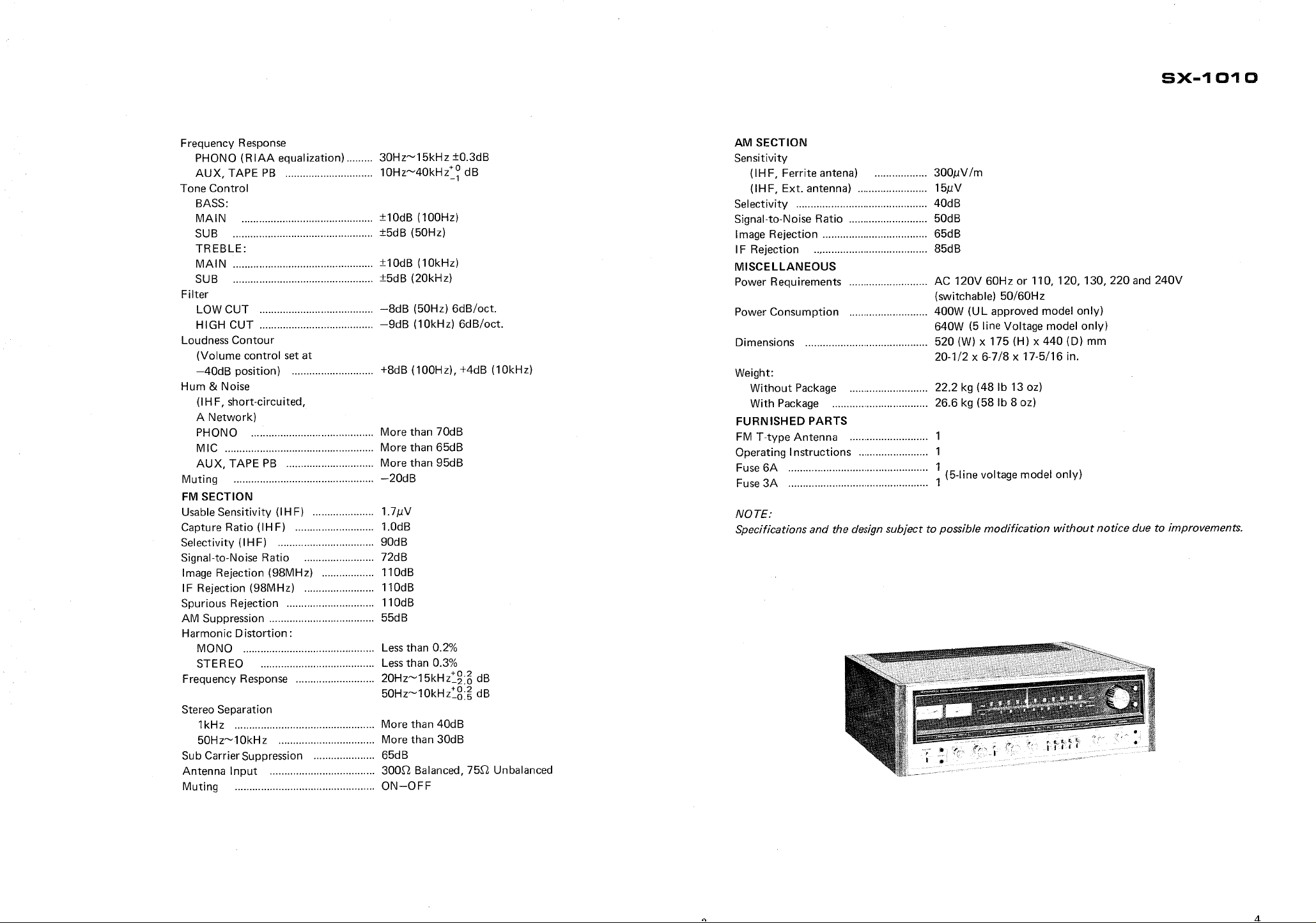
MISCELLANEOUS
Power Requirements
AC 120V 60Hz or 110
, 120, 130
220 and 240V
(switchable) 50/60Hz
Power Consumption
400W (UL approved model only)
640W (5 line Voltage model only)
Dimensions
Weight:
Without Package
With Package
520 (W) x 175 (H) x 440 (D) mm
1/2 x 6-7/8 x 17-
20-
5/16 in.
22.2 kg (48 Ib 13 oz)
26.
6 kg (58 Ib 8 oz)
FURNISHED PARTS
FM T-type Antenna
Operating Instructions
Fuse 6A
Fuse 3A
line voltage model only)
~ (5-
NOTE:
Specifications and the design subject to possible modification without notice due to improvements.
FRONT PANEL FACiliTIES
.,~..
. . . ..
. . ..
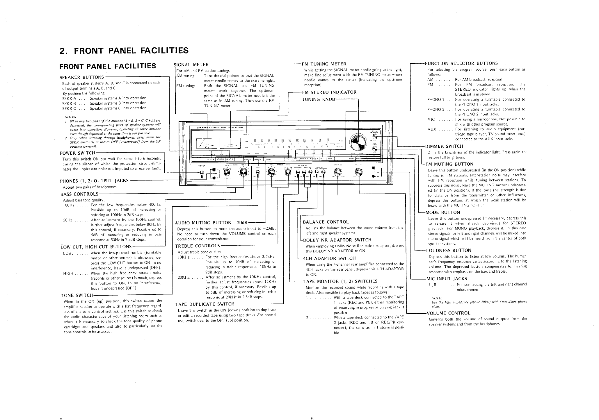
FRONT PANEL FACILITIES
SPEAKER BUTTONS
Each of speaker systems A
of output terminals A
By pushing the following:
SPKR-
SPKR-
SPKR-
NOTES:
Whenanytwopairsofthebuttons(A+B
1.
depressed
come into operation. However
even though depressed at the same time
2. Only when listening through headphones
SPKR button(s) in us" to OFF
position (pressed).
Speaker systems A into operation
A ....
Speaker systems B into operation
B ....
Speaker systems C into operation
C ....
, the corresponding
POWER SWITCH
Turn this switch ON but wait for
during the silence of which the protection circuit elimi-
nates the unpleasant noise not imputed to a receiver fault.
PHONES (1
, 2) OUTPUT
Accept two pairs of headphones.
BASS CONTROLS
Adjust bass tone quality.
100Hz. . .. For
50Hz. . . . . . After
Possible up to
reducing at 100Hz in 2dB steps.
further adjust frequencies below 80Hz by
this control
5dB of
response at 50Hz in 2.
LOW CUT
LOW.
HIGH
TONE SWITCH
When in the ON (up) position
amplifier section to operate with a flat frequency
less of the tone control settings. Use this switch to check
the audio characteristics of your listening room such as
when it is
cartridges and speakers and also to particularly set the
tone controls to be assessed.
, HIGH CUT
When the low-
motor or other
press the LOW CUT button to ON. In no
interference
When the high
(records or other source) is much
this button to ON. In no interference
leave it undepressed (OFF).
necessary to check the tone quality of phono
, and C is connected to each
, B
, B, and C.
pairs of speaker systems ;"iIl
, operating all three button"
B+C C+A)are
is not possible.
, press again the
(undepressed) from the ON
some 3 to 6 seconds
JACKS
frequencies below 400Hz.
the low
lOdB of
adjustment by the 100Hz control
necessary. Possible up to
, if
increasing or reducing in bass
increasing or
5dB steps.
BUTTONS
pitched rumble (turntable
source) is obtrusive
, leave it undepressed (OFF).
frequency scratch noise
, this switch causes the
, depress
, de-
regard-
SIGNAL METER
For AM and FM station tunings
AM tuning: Tune
FM tuning:
AUDIO MUTING BUTTON -
Depress this button to mute the audio input to -
No need to turn down the
occasion for your convenience.
the dial pointer so that the SIGNAL
meter needle comes to the extreme right.
Both the SIGNAL and FM
meters work
together. The
TUNING
optimum
point of the SIGNAL meter needle
same as in AM tuning. Then use the FM
TUNING meter.
"'"'0 """"'" -do. ".
.0'0
20dB
VOLUME control on each
TREBLE CONTROLS
Adjust treble tone quality.
10KHz
20KHz
.. For the high frequencies above 2.
Possible up to
reducing in treble response at 10kHz in
2d B steps.
.. After adjustment by the
10dB of
increasing or
10KHz control
further adjust frequencies above
by this control
to 5dB of increasing or reducing in treble
response at 20kHz in 2.
, if necessary. Possible up
5dB steps.
TAPE DUPLICATE SWITCH
Leave this switch in the ON (down) position to duplicate
or edit a recorded tape using two tape decks. For normal
use, switch over to the OFF (up) position.
is the
20dB.
5kHz.
12KHz
FM TUNING METER
While getting the SIGNAL meter needle going to the right
make fine adjustment with the FM TUNING meter
needle comes to the
center (indicating the optimum
reception).
-FM STEREO INDICATOR
TUNING KNOB
BALANCE CONTROL
Adjusts the balance between the sound volume from the
left and right speaker systems.
DOLBY NR ADAPTOR SWITCH
When employing Dolby Noise Reduction Adaptor
this DOLBY NR ADAPTOR to ON.
4CH ADAPTOR SWITCH
When using the 4-channel rear amplifier connected to the
4CH jacks on the rear panel
to ON.
TAPE MONITOR (1
Monitor the recorded sound while
deck. Also possible to play back tapes as follows:
1 . . .
With a tape deck connected to the TAPE
1 jacks (REC and PB), either monitoring
of recording in progress or playing back is
possible.
. .. With a tape deck connected to the
2 jacks (REC and PB or
, depress this 4CH ADAPTOR
2) SWITCHES
recording with a tape
REC/PB con-
nector), the same as in 1 above
ble.
whose
, depress
TAPE
is possi-
FUNCTION SELECTOR BUTTONS
For selecting the program source
follows:
AM..
For AM broadcast reception.
For FM
STEREO indicator lights up
broadcast is in stereo.
PHONO 1
PHONO 2
MIC
AUX
.. For operating a
the PHONO 1 input jacks.
For operating a turntable connected to
the PHONO 2 input jacks.
For using a microphone. Not possible to
mix with other program source.
For listening to audio equipment
tridge tape player
connected to the ALJX input jacks.
, push each button as
broadcast
reception. The
turntable connected to
, TV sound tuner
when the
, etc.
DIMMER SWITCH
Dims the brightness of the indicator light. Press
restore full brightness.
again to
FM MUTING BUTTON
Leave this button undepressed (in the ON position) while
tuning in FM stations. Inter-station noise may interfere
with FM
suppress this noise
ed (in the ON position). If the low
to distance from the
depress this button
heard with the MUTING "
reception while tuning between stations. To
, leave the MUTING button undepress-
signal strength is due
transmitter or other influences
, at which the weak
station will be
OFF.
MODE BUTTON
Leave this button undepressed (if
to release it when already depressed) for
playback. For MONO playback
stereo signals for left and right channels will be mixed into
mono signal which will be heard from the center of both
speaker systems.
LOUDNESS BUTTON
Depress this button to listen at low volume.
ear s frequency response varies according to the listening
volume. The depressed button compensates for
response with emphasis on the bass and treble.
MIC INPUT JACKS
, R . . .
NOTE:
Use the high impedance (above 20M2) with 6mm diam. phone
plug,.
.. For connecting the
microphones.
necessary, depress this
STEREO
, depress it. In this case
The human
hearing
left and right channel
VOLUME CONTROL
Governs both the volume of sound
speaker systems and from the headphones.
outputs from the
(car-
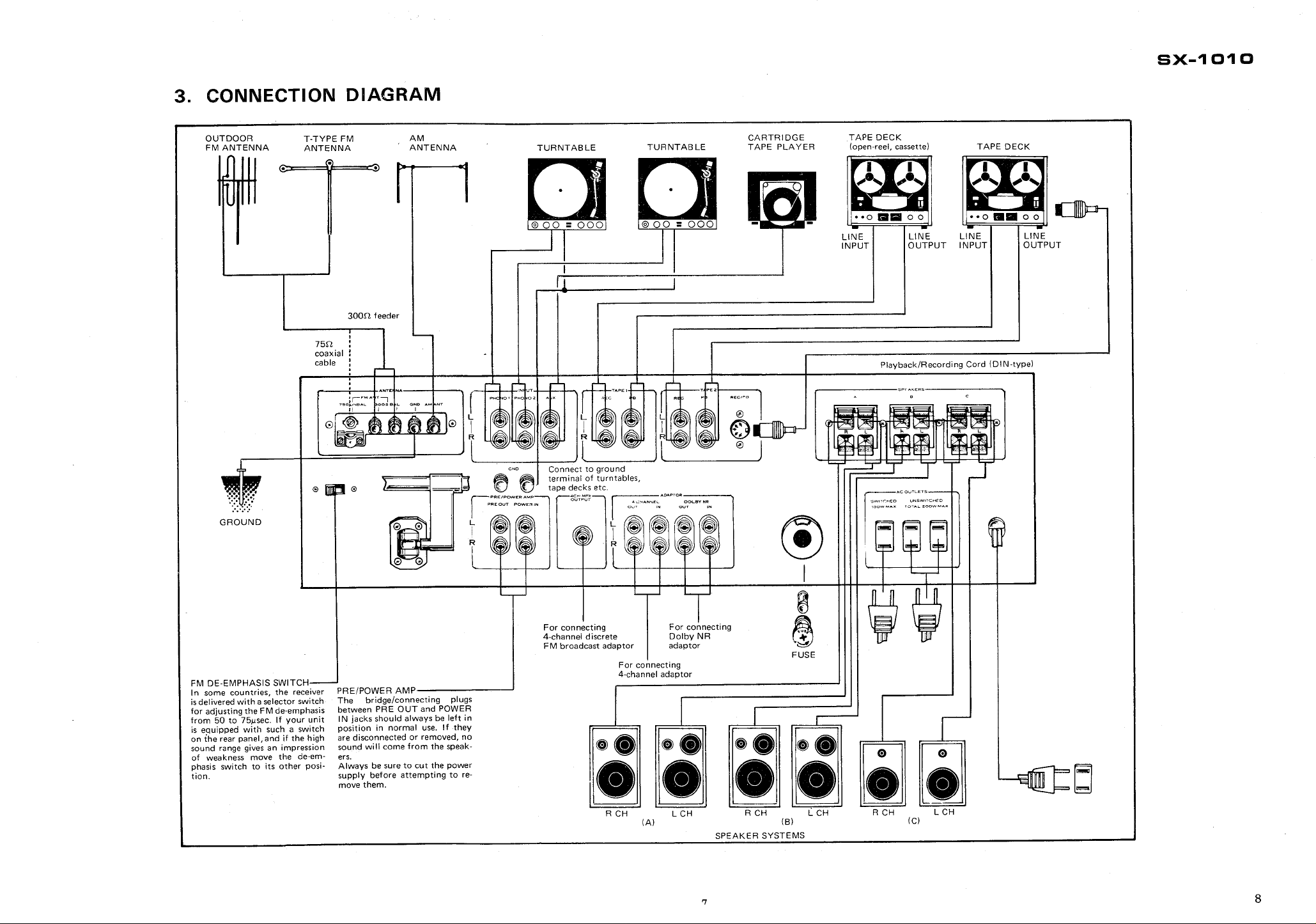
CONNECTION DIAGRAM
SX-
1 01 0
OUTDOOR
FM ANTENNA
TYPE FM
ANTENNA
75n :
coaxial:
cable
300n feeder
ANTENNA
TURNTABLE
TURNTABLE
CARTRIDGE
TAPE PLAYER
TAPE DECK
(open-reel, cassette) TAPE DECK
LINE
INPUT
LINE
OUTPUT
Playback/Recording Cord (DIN-
LINE
INPUT
LINE
OUTPUT
type)
GROUND
FM DE-EMPHASIS SWITCH
I n some countries
is delivered with a selector switch
for adjusting the FM de-
from 50 to 75!lsec. If your unit
is equipped with such a switch
on the rear panel
sound range gives an impression
of weakness move the de-em-
phasis switch to its other posi-
tion.
. the receiver
emphasis
, and if the high
PRE/POWER AMP
bridge/connecting plugs
The
between PRE OUT and POWER
I N jacks should always be left in
position in normal use. If they
are disconnected or removed
sound will come from the speak-
ers.
Always be sure to cut the power
supply before attempting to re-
move them.
, no
For connecting
4-channel discrete
FM broadcast adaptor
For connecting
- R CH
For connecting
Dolby NR
adaptor
channel adaptor
L CH
(A)
SPEAKER SYSTEMS
FUSE
R CH
(B)
L CH
R CH
(C) L
,?,,'
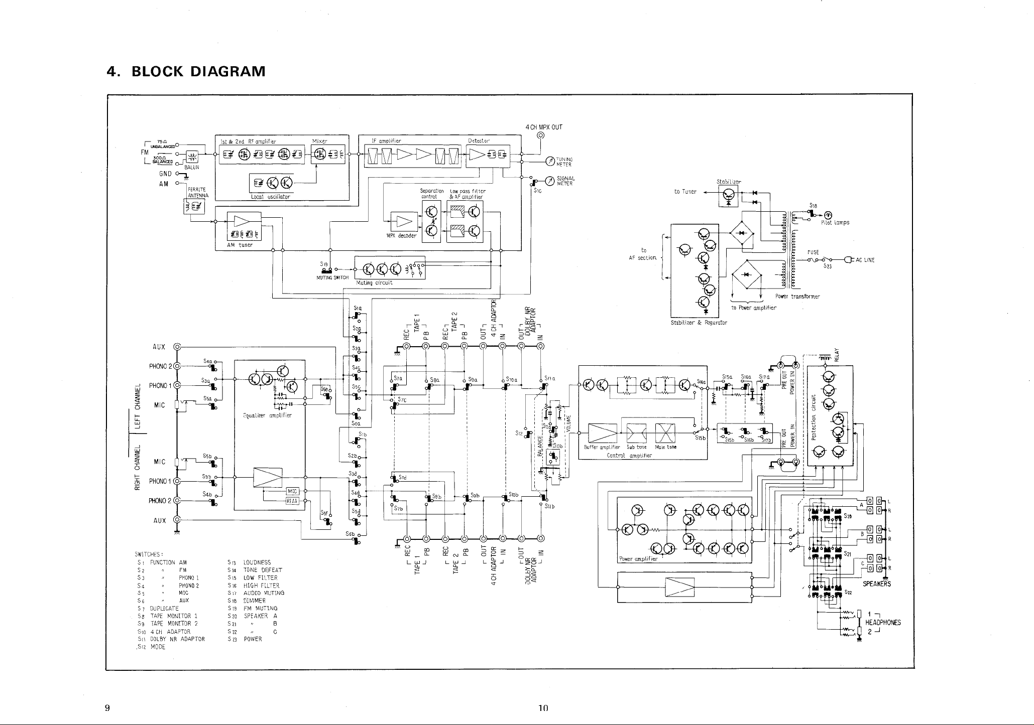
BLOCK DIAGRAM
':~~CED
FM
L".-i1CED
~ ~
4 CH MPX OUT
(C?)
l)
~~L
~" --" "
Stabilizer
to Tuner
S18
::rll""
AUX
MIC
MIC
or:
:r:
PHONO 2 (0
AUX
SWITCHES'
S 1 FUNCTION
S 2
S 3
S 4
S 5
DUPUCATE
TAPE MONITOR 1
TAPE MONITOR 2
SlO
4 CH ADAPTOR
SI1
DOLBY NR ADAPTOR
S,Z
MODE
PHONO 1
PHONO 2
MIC
AUX
S i1 LOUDNESS
S 14 TONE
S15 LOW FILTER
S 16 HIGH fILTER
S 17 AUDIO MUTING
S 18 DIMMER
S 19 FM
S 20 SPEAKER A
S"
S22
S 23 POWER
DEFEAT
MUTING
S19
MUTiNG
SWiTCH
SIQ
CO r-
a:: CL.
a:: - CL.
L w.J
CL.
CL.
r "",
CO r-
CL.
a::
i'cl co
a:: N CL.
L w..J
CL.
or:-'
r- co
::0 "" 2
0 -
Sa:: 2
0 ~-
L 8-!
:r:
~6~-'
::00 2
0 -
S'0a
, 0--
r- 2
::0 -
'C ~gj-!
a::a::
iDh:
';)h:
S11 a
' Sl1b
AF section
Stabilizer d:c Regurator
S'40
'-----v----'
to Power amplifier
J~~~""'
-Q-Q-

SX-
1 01 0
CIRCUIT DESCRIPTION
SIGNAL PATH
1. The FM broadcast
antenna is fed to the two dual-
field-effect transistors in the front end
radio frequency amplification. This
converted into an intermediate frequency by
the dual-
bination with the
gate MOS FET mixer stage in com-
lator.
2. The
intermediate frequency signal
verted within the front end
ceramic filters and three ICs
, amplified
tuned
audio frequency (composite) signal.
The composite
fed to the 4 CH MPX terminal jack
multiplex decoder stage.
3. The multiplex decoder stage
three functions: to
posite signal into the left and right
stereo signals
mode switching between stereo/mono
to switch the
priately.
The decoding system uses a phase locked
loop (PLL) circuit
stable operation and excellent
ration with low
noise (such as
ambient temperature changes.
After decoding, the
transistors and one LC filter
residual carrier component (38kHz
and SCA) is rejected
amplifier section.
4. The FM muting circuit consists effectively of
two circuits, designed to reduce the pulse
noise which can so
muting circuit is operative.
The one circuit is an
corporated into the IC
modulated circuit is
the IC
, and the other short-
signal by means of a reed relay.
5. The AM tuner section
lithic IC which functions as radio frequency
amplifier
lator
detector. The output is a pure
6. The signals which are applied to the MIC and
PHONO terminal jacks are selected by the
FUNCTION switch before being fed to the
first stage of the three-
direct-coupled equalizer amplifier by which
the signals are amplified.
In order to reduce the
circuit configuration employed enables the
potential at the input and output terminals
to be set at near zero volts.
, frequency converter
, intermediate frequency amplifier
signal waveform from the
gate MOS
for
signal is
signal from the local oscil-
, con-
, is fed to four
, where it is
, and detected
, becoming a
signal following detection is
and the
uses one IC for
demodulate the com-
channel
, to operate the automatic
, and
stereo indicator lamp appro-
, which assures continuous
stereo sepa-
susceptibility to external
ignition noise) and
car
signal is fed to four
, and then to the audio
easily arise
, where the
, 19kHz
when a
electronic switch in-
, so that the de-
switched off and on in
circuits the audio
employs one mono-
, local oscil-
, and
audio signal.
stage differential
switch noise
, the
It incorporates an independent differential
circuit in the first stage of the
equalizer
amplifier whose DC supply uses twin plus
and minus.
7. The output from the equalizer amplifier
together with that from the
jacks, the audio
and the audio signal from the FM tuner
all selected by the FUNCTION switch
pass through the switch circuits for TAPE
DUPLICATE
ADAPTOR DOLBY NR ADAPTOR
signal from the AM tuner
, TAPE MONITOR, 4 CH
AUX terminal
, are
, and
, and
the circuits for BALANCE and VOLUME
controls, before being fed to the control
amplifier.
8. The control amplifier has an extremely high
input impedance
sistors in a
This greatly reduces the influence of the
performance inherent in equipment
nected externally.
The output from this two-
coupled circuit is
systems.
One goes to the TONE switch via the twin
tone control circuit, and the other goes
directly and unmodified in any way
TONE
between them.
switch. The TONE switch selects
9. The amplifier section of the twin control has
closed loop NFB
main and sub circuits
own transistor
ference.
10. The control amplifier output is fed to the
power amplifier after
LOW FILTER, HIGH FILTER and AUDIO
MUTING circuits.
The first stage of the power amplifier is a
differential amplifier element with constant
current load, and the second stage
a differential amplifier element, so that DC
potential drift is prevented.
On the other hand, the final output stage
uses two power transistors in parallel in both
the upper and lower circuits
collector dissipation is possible.
Again, in order to reduce the
which occurs at low
current has been set at a standard
100mA.
11. The power amplifier output is fed to
three push
SPEAKER switch. This selects A
speaker system terminal connection.
If all three speaker systems were to
connected
speaker impedance might be less than 4il.
To guard
three buttons are
three systems are
amplifier.
12. The power amplifier circuit board includes a
, using PNP and NPN tran-
direct-coupled two-stage circuit.
con-
stage direct-
divided into two circuit
.to the
amplifiers for both the
, each of which has its
, eliminating mutual inter-
passing through the
, too, uses
, so that large
distortion
signal levels, the idle
level of
the
buttons which form
simultaneously, the
, and C
, B
effective
the
against this possibility, when all
depressed together
, all
disconnected from the
power limiter circuit which is independent
of the signal
current exceeds the maximum rated value
the power limiter circuit
signal to protect the power transistors.
The 'sensing ' for this protective
performed by
across the emitter
transistors. There are also protective circuit
which guard
power amplifier output junctions
circuit. If the power transistor
shorts the input
circuit is
detecting the voltage drop
resistors of the
power
against DC potentials at the
, against
speaker complex load impedances less than
, and shorts across the speaker terminals.
Their operation is such that
responding abnormal condition
, under the cor-
, a relay acts
to separate the output junction and the
output
circuits also help to
signal which immediately follows switching
the POWER switch ON
disconnect the output after switched OFF.
circuit. Further
, these
mute the unwanted
, and to immediately
protective
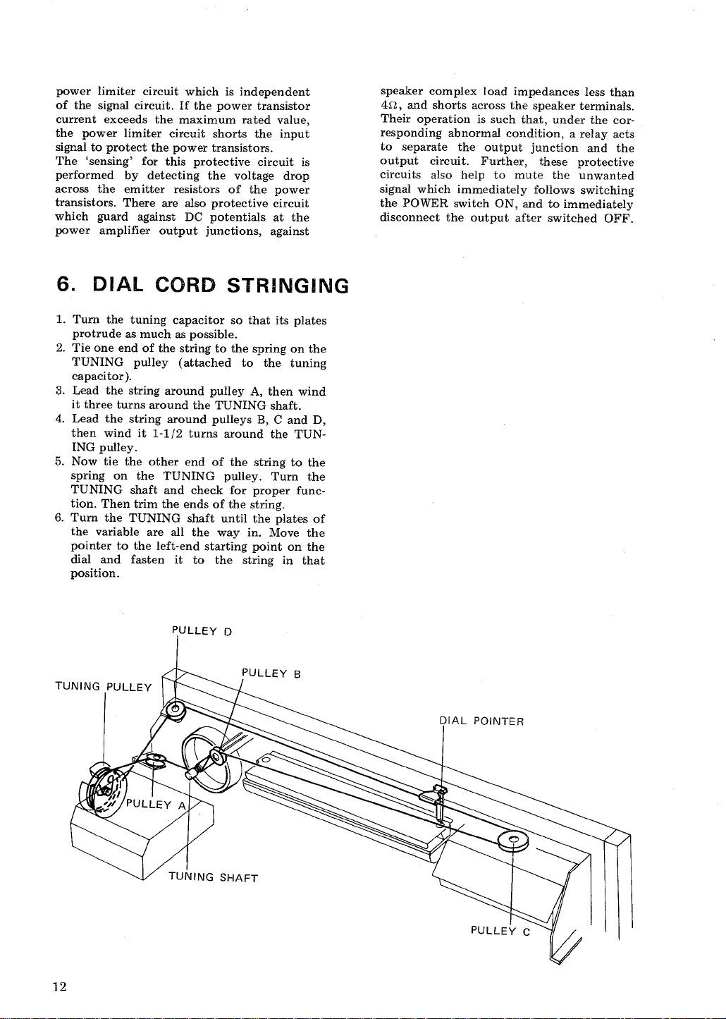
DIAL CORD
STRINGING
1. Turn the tuning capacitor so that its plates
protrude as much as possible.
2. Tie one end of the string to the spring on the
TUNING pulley (attached to
capacitor ).
3. Lead the string around pulley A
it three turns around the TUNING shaft.
4. Lead the string around pulleys B
then wind it 1-
ING pulley.
1/2 turns around the TUN-
5. Now tie the other end of the
spring on the
TUNING pulley. Turn the
the tuning
, then wind
, C and D
string to the
TUNING shaft and check for proper func-
tion. Then trim the ends of the string.
6. Turn the TUNING shaft until the
the variable are all the way in.
pointer to the left-end starting point on the
dial and fasten it to the
position.
PULLEY D
TUNING PULLEY
plates of
Move the
string in that
DIAL POINTER
""' '""~ ~
. g
~~p~~
"""
~%-~"'"
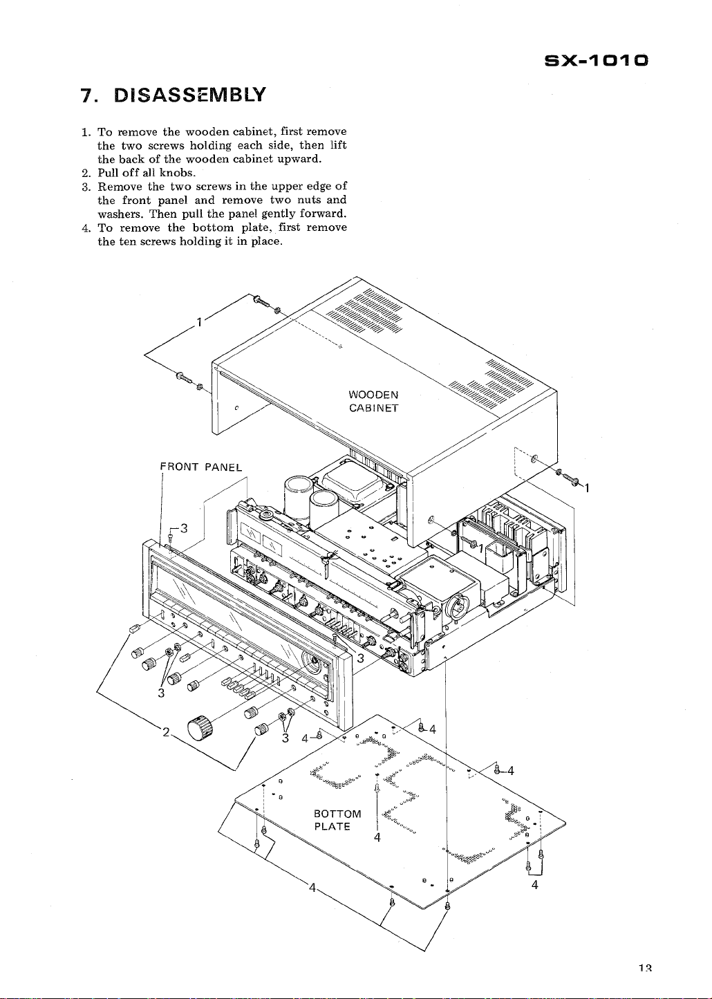
DISASSEMBLY
1. To remove the wooden cabinet
the two screws holding each side
the back of the wooden cabinet upward.
2. Pull off all knobs.
3. Remove the two
the front panel and
washers. Then pull the panel gently forward.
remove the bottom plate
4. To
the ten screws holding it in place.
screws in the upper edge of
remove two nuts and
, first remove
, then lift
, first remove
WOODEN
CABINET
~i'
SX-
1 01
FRONT PANEL
~" '0
I%~"
~~~~~M
4 0
" 0
0 ~
:~o
~ o
1 ~
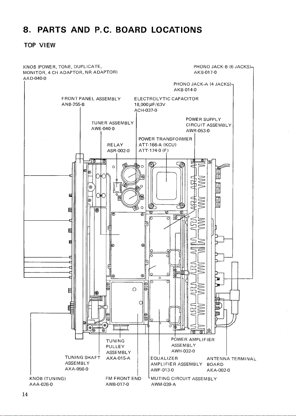
PARTS AND
TOP VI EW
P. C. BOARD LOCATIONS
KNOB (POWER
MONITOR
AA D-
, 4 CH ADAPTOR
040-
, DUPLICATE
, TONE
FRONT PANEL ASSEMBLY
ANB-255-
, NR ADAPTOR)
TUNER ASSEMBLY
AWE-
040-
C3)
C3)
RELAY
ASR-002-
PHONO JACK-
AKB-014-
ELECTROLYTIC CAPACITOR
000 IlF /63V
ACH-037-
POWER SUPPLY
CIRCUIT ASSEMBLY
AWR-
POWER TRANSFORMER
166-
ATTATT-
174-
A (KCU)
0 (F)
PHONO JACK-
AKB-017-
A (4 JACKS)
053-
B (6 JACKS)
KNOB (TUNING)
AAA-
026-
TUNING
PU LLEY
ASSEMBL Y
TUNING SHAFT AXA-
ASSEMBL Y
AXA-056-
FM FRONT END
AWB-017-
015-
POWER AMPLIFIER
ASSEMBL Y
AWH-
032-
EQUALIZER
ANTENNA TERMINAL
AMPLIFIER ASSEMBLY BOARD
AWF-013-0 AKA-
MUTING CIRCUIT ASSEMBLY
AWM-
039-
002-
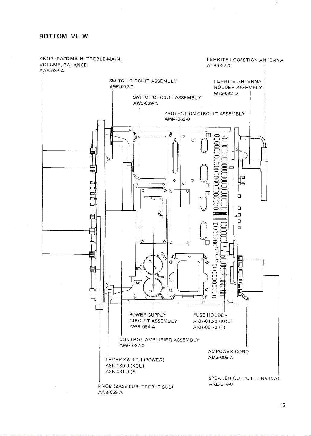
BOTTOM VIEW
g =
KNOB (BASS-
VOLUME
AAB-
, BALANCE)
068-
MAIN , TREBLE-
MAIN
SWITCH CIRCUIT ASSEMBLY
AWS-072-
SWITCH CIRCUIT ASSEMBLY
AWS-
069-
PROTECTION CIRCUIT ASSEMBLY
AWM-062-
FERRITE LOOPSTICK ANTENNA
ATB-O27-
FERRITE ANTENNA
HOLDER ASSEMBLY
W72-
092-
ill =
0 ~!
0 I~
OJ
CJ
OJ
0 ~~
POWER SUPPLY
CIRCUIT ASSEMBLY
AWR-
054-
CONTROL AMPLIFIER ASSEMBLY
AWG-027-
LEVER SWITCH (POWER)
ASK-080-
ASK-
KNOB (BASS-
AA B-069-
0 (KCU)
081-
0 (F)
SUB, TREBLE-
0 0
SUB)
0 i~
CD
69 0
(g) CJ
FUSE HOLDER
AKR-012-
AKR-001-
0 (KCU)
0 (F)
AC POWER CORD
ADG-005-
SPEAKE R OUTPUT TE RM
AKE-O14-
I NAL
:~ ~
" "
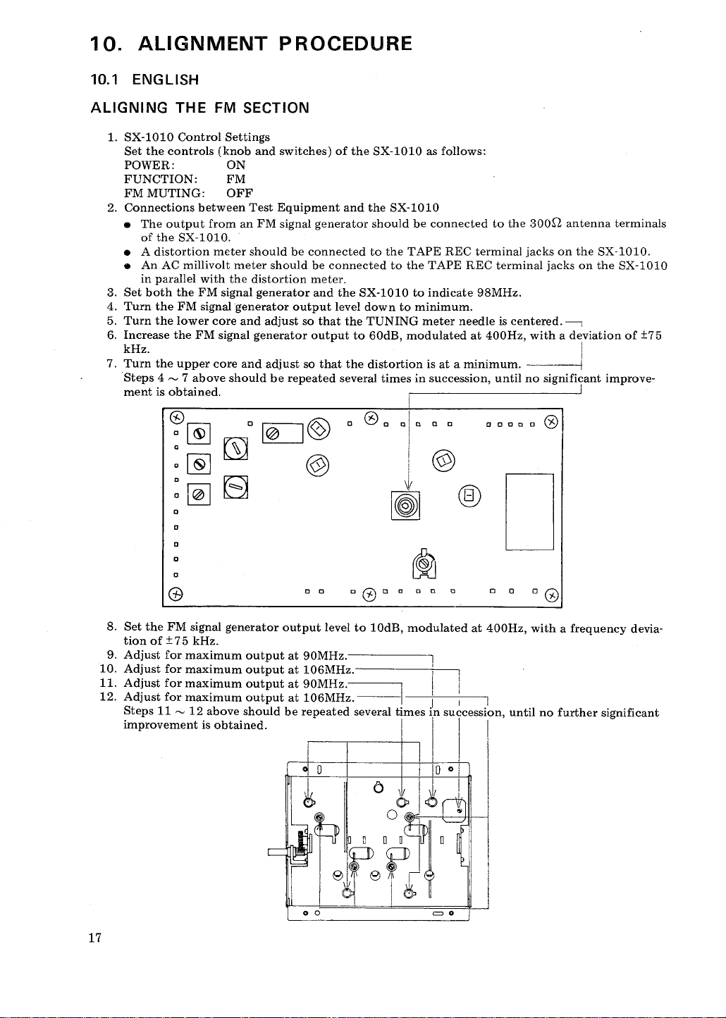
10.
10. ENGLISH
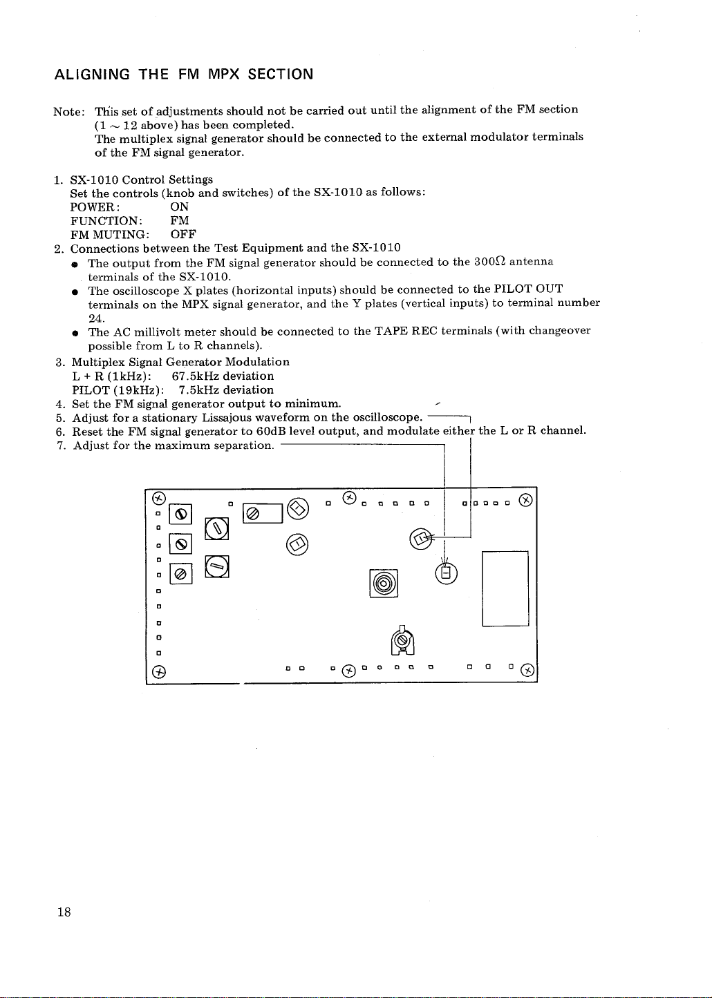
ALIGNING THE FM SECTION
ALIGNMENT PROCEDURE
1. SX-1010 Control Settings
Set the controls (knob and switches) of the SX-
1010 as follows:
POWER:
FUNCTION: FM
FM MUTING: OFF
2. Connections between Test Equipment and the SX-1010
. The output
of the SX-1010.
. A distortion meter should be connected to the TAPE REC terminal jacks on the SX-
. An AC millivolt meter should be connected to the TAPE REC terminal jacks on the SX-
in parallel with the distortion meter.
3. Set both the FM signal
4. Turn the FM
5. Turn the lower core and adjust so that the TUNING meter
6. Increase the FM signal generator output to 60dB
from an FM signal generator should be connected to the 300Q antenna terminals
generator and the SX-
signal generator output level down to minimum.
1010 to indicate 98MHz.
needle is centered.---r
, modulated at 400Hz, with a deviation of
kHz.
7. Turn the upper core and adjust so that the distortion is at a
Steps 4 ~ 7 above should be repeated
ment is obtained.
several times in succession, until no significant improve-
" 0"
c Ie
~&J
minimum.
aa""a
(Z)
I010.
1010
:1:75
:~ 8
(1)
8. Set the FM signal generator output level to 10dB
tion of :1:75
9. Adjust for maximum output at 90MHz.
10. Adjust for maximum output at 106MHz.
11. Adjust for maximum output at 90MHz.
12. Adjust for maximum output at
Steps 11 ~ 12 above should be repeated
kHz.
impmvomenti, ob',;ned.
c "
106MHz.
0 0 = 0
" 0)" "
several times in succession
e,f
c c 0 "
, modulated at 400Hz
i 0 0
0 &
r $
1 (
I ~ t
, with a frequency devia-
, until no further significant
:~
ALIGNING THE FM
Note: This
1. SX-
Set the controls (knob and switches) of the SX-
set of adjustments should not be carried out until the alignment of the FM section
(1 ~ 12 above) has been completed.
The multiplex signal generator should be connected to the external
of the FM signal generator.
1010 Control Settings
MPX SECTION
modulator terminals
1010 as follows:
POWER:
FUNCTION: FM
FM MUTING:
2. Connections between the Test Equipment and the SX-
. The output
terminals of the SX-
. The oscilloscope X plates (horizontal inputs) should be connected to the PILOT OUT
terminals on the MPX signal generator
24.
. The AC
possible from L to R channels).
3. Multiplex Signal Generator Modulation
L + R (1kHz): 67.
PILOT (19kHz): 7.5kHz deviation
4. Set the FM signal generator output to minimum.
5. Adjust for a stationary Lissajous
6. Reset the FM signal generator to 60dB level output
7. Adjust for the maximum separation.
OFF
1010
from the FM signal generator should be connected to the
1010.
, and the Y plates (vertical inputs) to terminal number
millivolt meter should be connected to the TAPE REC
5kHz deviation
waveform on the oscilloscope.
, and modulate either the L or R channel.
300,Q antenna
terminals (with changeover
:~ 8
aocco 0
~ D
a a
" "
SX-
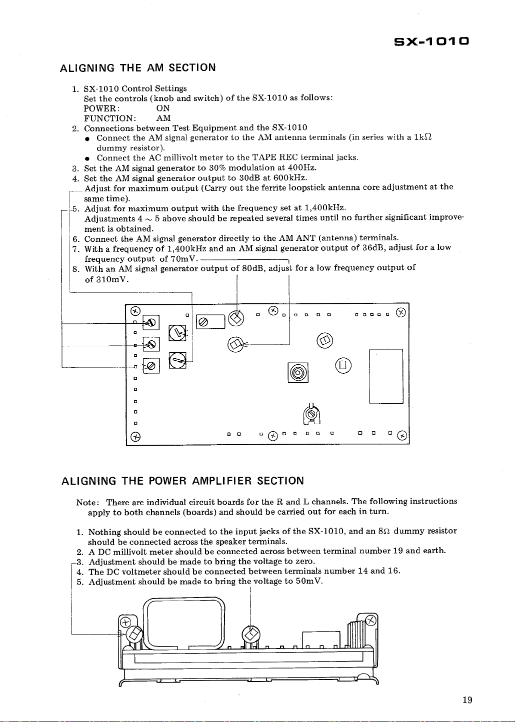
ALIGNING THE AM SECTION
1010 Control Settings
1. SX-
Set the controls (knob and switch) of the SX-
1010 as follows:
POWER:
FUNCTION: AM
2. Connections between Test Equipment and the SX-
. Connect
dummy resistor).
. Connect the AC millivolt meter to the TAPE REC terminal jacks.
3. Set the AM signal generator to
4. Set the AM signal
Adjust for maximum output (Carry out the ferrite loopstick antenna core adjustment at the
same time).
-5. Adjust for maximum output with the frequency set at 1
Adjustments 4 ~ 5 above should be repeated several times until no further significant
ment is obtained.
. Connect the AM signal
7. With a frequency of 1
frequency output of 70mV.
8. With an AM signal generator output of 80dB
the AM signal generator to the AM antenna terminals (in series with a
30% modulation at 400Hz.
generator output to 30dB at 600kHz.
generator directly to the AM ANT (antenna) terminals.
400kHz and an AM signal generator output
1010
400kHz.
of 36dB
, adjust for a low frequency output of
, adjust for a low
of 310mV.
",,"c" ~
1 01 0
1k,Q
improve-
(0)
" a
ALIGNING THE POWER AMPLIFIER
Note: There are individual circuit boards for the Rand L channels. The following instructions
apply to both channels (boards) and should be carried out for each in turn.
1. Nothing should be connected to the input jacks of the SX-
should be connected across the speaker terminals.
2. A DC millivolt meter should be connected across between terminal number 19 and earth.
3. Adjustment should be made to bring the voltage to zero.
4. The DC voltmeter should be connected between terminals number 14 and 16.
5. Adjustment should be made to bring the voltage to 50m
" CD a
SECTION
101O, and an 8.\1 dummy resistor
a 0
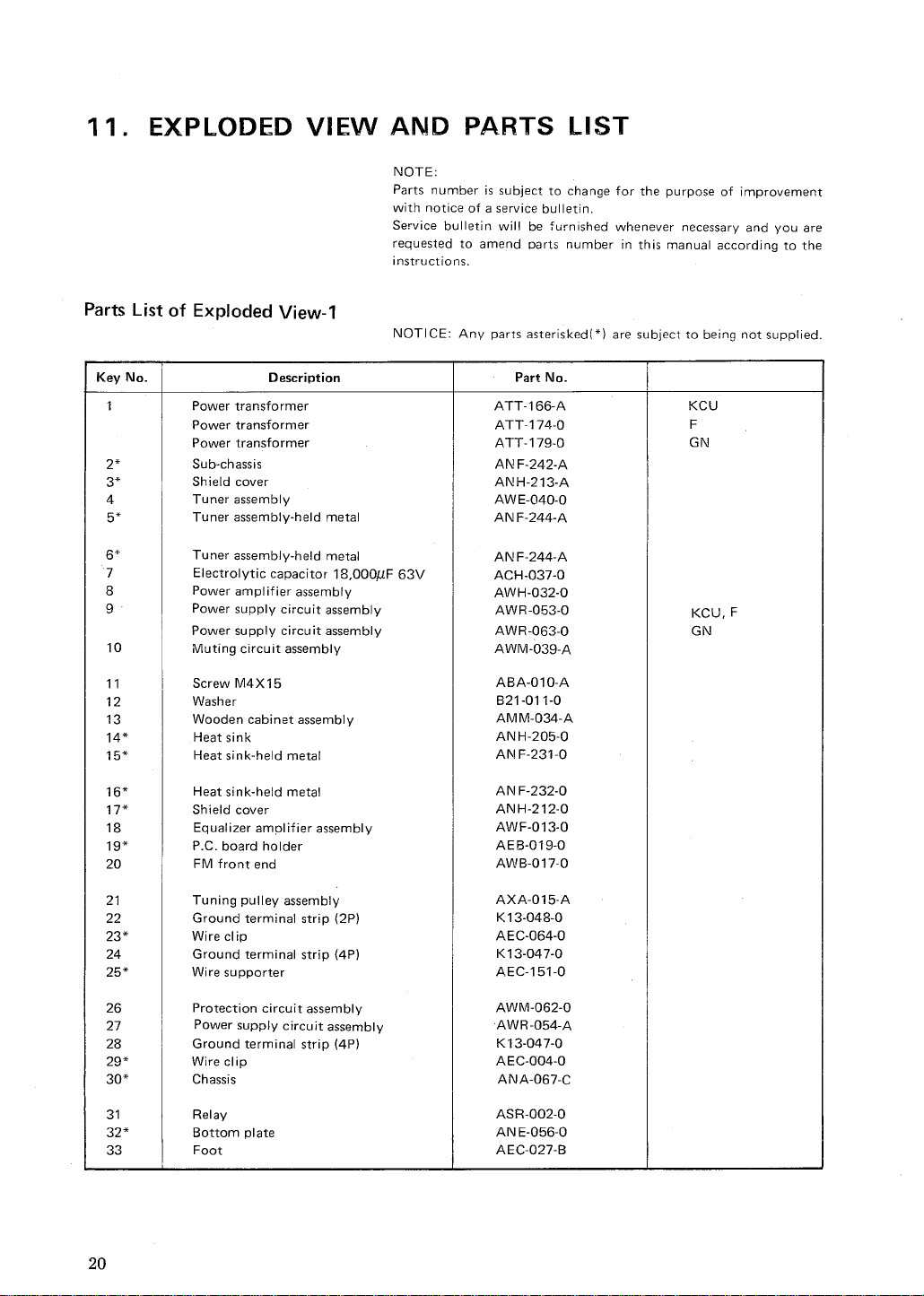
11 . EXPLODED VIEW AND PARTS
NOTE:
Parts number is subject to change for the purpose of improvement
with notice of a service bulletin.
Service bulletin will be furnished
requested to amend parts number in this
instructions.
Parts List of Exploded View-
NOTICE: Any parts asterisked(*
LIST
whenever necessary and you are
manual according to the
) are subject to being not supplied.
Key No.
Power transformer ATT-
Power transformer
Power transformer ATT- 179-
Sub-chassis AN F-
Shield cover
Tuner assembly
Tuner assembly-held metal
Tuner assembly-
Electrolytic capacitor 18
Power amplifier assembly
Power supply circuit assembly
Power supply circuit assembly AWR-
Muting circuit assembly
Screw M4X15
Washer
Wooden cabinet assembly
14*
15*
16*
17* Shield cover
Heat sink
Heat sink-held metal
Heat sink-held metal
Equalizer amplifier assembly
19*
C. board holder
FM front end
Description
held metal
00011F 63V
Part No.
166-
174-
ATT-
242-
ANH-213-
AWE-
O40-
AN F-244-
AN F-244-
ACH-037-
AWH-032-
A\llJR-053-
063-
AWM-
039-
ABA-OlO-
B21-011-
AMM-
034-
ANH-205-
AI\! F-231-
AN F-
232-
ANH-212-
AWF-013-
AEB-019-
AWB-017-
KCU
KCU, F
Tuning pulley assembly AXA-
Ground terminal strip (2P)
23*
Wire clip
Ground terminal strip (4P)
25*
Wire supporter AEC-151-
Protection circuit assembly AWM-062-
Power supply circuit assembly
Ground terminal strip (4P)
29* Wire clip
30*
32* Bottom plate
Chassis ANA-
Relay ASR-002-
Foot AEC-
015-
K13-048-
AEC-064-
K13-
047-
AWR-
054-
K13-
047-
AEC-004-
067-
AN E-056-
027-
...
;:::; ~
Ci)'
c..
c::::
c..

, -
, -
Parts List of Exploded View-
Key No.
Dial scale
Dial scale-held metal
Dial pointer
Meter (Signal & tuning)
Lamp Box
Lamp holder
Pilot lamp socket
Pilot lamp 8V
C. board cover
Lamp board assembly
Pilot lamp 8V
12*
Lamp box
Pilot lamp 6V
Rubber bracket
Front panel assembly
Knob (Power
Knob (Bass-sub)
Knob (Bass-main)
Knob (Treble-main
Ornamental ring AAC-
Knob (Tuning)
Knob (Treble-
Knob (Dimmer
Coupler (knob-to-
Spacer
Bush
Knob (SPKR A
Knob (Low cut
Knob (Function)
Knob (Mode
Lever switch (Power!
Lever switch (Power)
Phone jack (Headphone)
Shading plate
Nut (insulator)
35* Sub-chassis
Phone jack (Microphone)
Switch circuit assembly
38*
Shield cover
Control amplifier assembly
40*
Pulley shaft
Description
, 0.3A (meter)
, 0.
3A (dial scale) E22-
, 30m A (stereo indicator) AEL-
, Tone, Duplicate, Monitor
4 CH adaptor, NR adaptor)
sub) AAB-
, FM muting)
switch)
, High cut
, Loudness)
NOTE:
Parts number is subject to change for the purpose of improvement
with notice of a service bulletin.
Service bulletin will be furnished whenever
requested to amend parts number in this
instructions.
NOTICE: Any parts asterisked(* ) are subject to being not supplied.
AAG-O72-
AN F-243-
AAF-031-
AAW-
ANH-
ANGAKK-
AEL-015-
ANG-
AWX-069-
ANH-210-
AEB-
AN B-
AAD-
AAB-
, Volume, Balance) AAB-
20dB)
AAB-
AAA-
AAD-
AAE-
AEC-
AEC-
AADAAD-065-
AADAAD-
ASKASK-081-
K72-
AED-018-
AEC-
AN D-
K72-
AWS-
ANH-
AWG-
M49-
Part No.
029-
211-
097002-
100-
032-
014-
031-
255-
040069068068-
034-
026069-
082007-
152-
160-
064-
066-
067-
080-
026-
085-
O72-
024-
072-
206-
027-
025-
necessary and you are
manual according to the
KCU
, GN
Key No.
41 *
Pulley AEC-153-
Rubber bracket AEB-057-
Pilot lamp 8V
44*
45*
Lamp holder
Pulley-held metal ANG-102-
46* Pulley
Rubber bracket
Rubber bracket
49*
50*
Sub-panel
Shading metal
Switch circuit assembly (dimmer)
Tuning shaft assembly
Switch circuit assembly (speaker)
Switch circuit assembly (filter
Switch circuit assembly (function)
Switch circuit assembly (mode
57*
Shield cover
Speaker output terminal
66*
Connector (AC power)
70*
Description
, 50 mA (position)
20dB)
, loudness)
Part No.
AEL-O23-
AN G-
AEC-101-
AEB-
AEB-
AND-
AN F-
AWS-068-
AXA-056-
AWSAWS-071-
AWS-069-
AWS-070-
ANH-208-
AKE-O14-
AC socket
5P connector assembly
Fuse holder (AC power)
Fuse holder (AC power)
Phono jack-
Phono jack (1 jack)
Phono jack-
A (4 jacks)
B (6 jacks)
Antenna terminal board
Rear panel
Rear panel
Rear panel
AC cord grommet
AC power cord
AC cord grommet
Model name plate
Model name plate
A KP-005-
AWX-062-
AKRc012-
AKR-001-
AKB-014-
AKB-019-
AKB-O17-
AKA-002-
ANC- 105-
AI\IC-
ANC-
AEC-O79-
ADG-005-
AEC-079-
AKP-008-
AAL-200-
AAL-204-
Model name plate AAL-
Binding post for ground AKE-
Ferrite loopstick antenna
ATB-
Ferrite antenna holder assembly W72-
099-
057-
O58-
073-
249-
064-
111-
113-
205-
012-
027-
092-
KCU, F
KCU
KCU
KCU
KCU
KCU
, F
, F
')':1
,)A
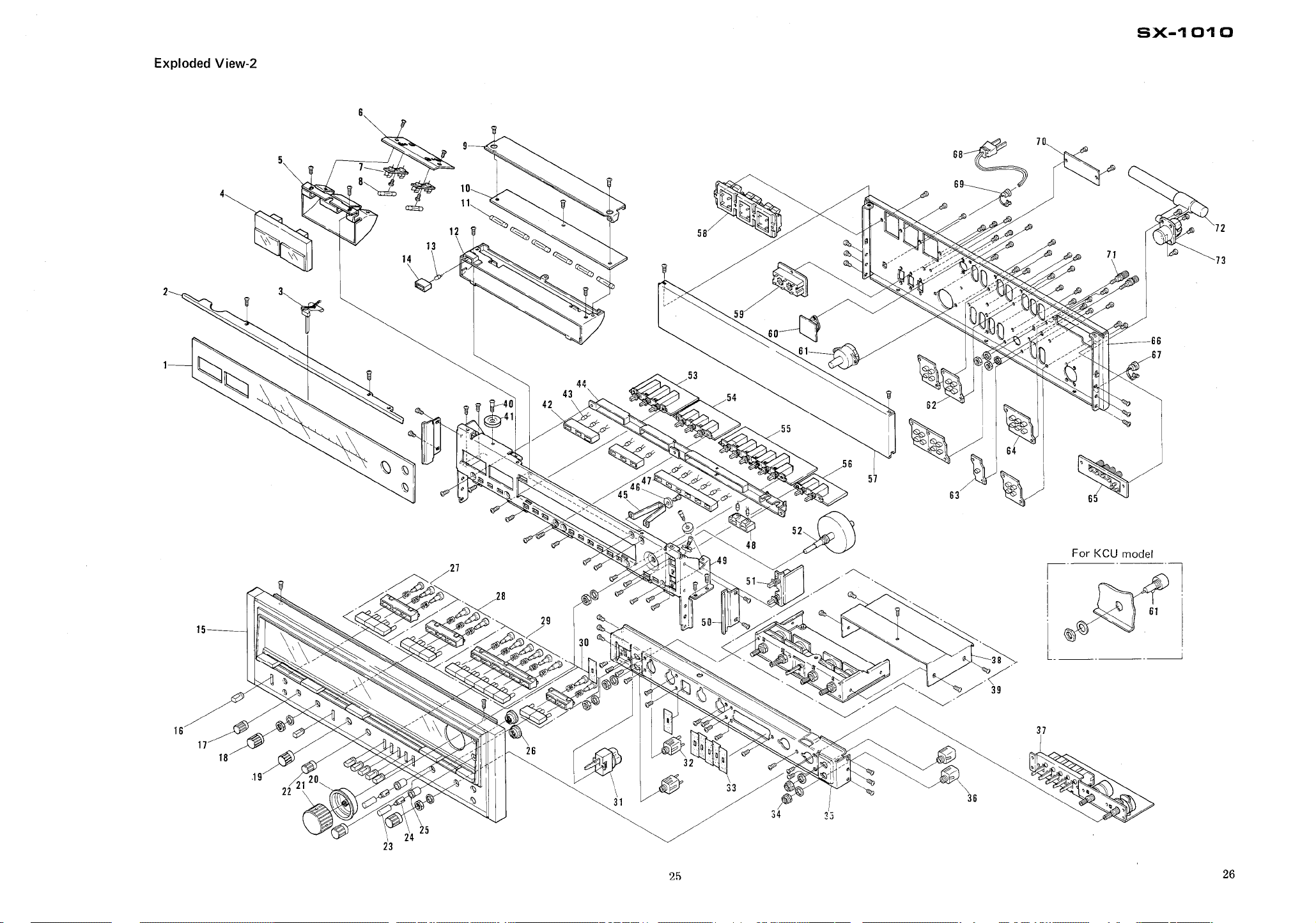
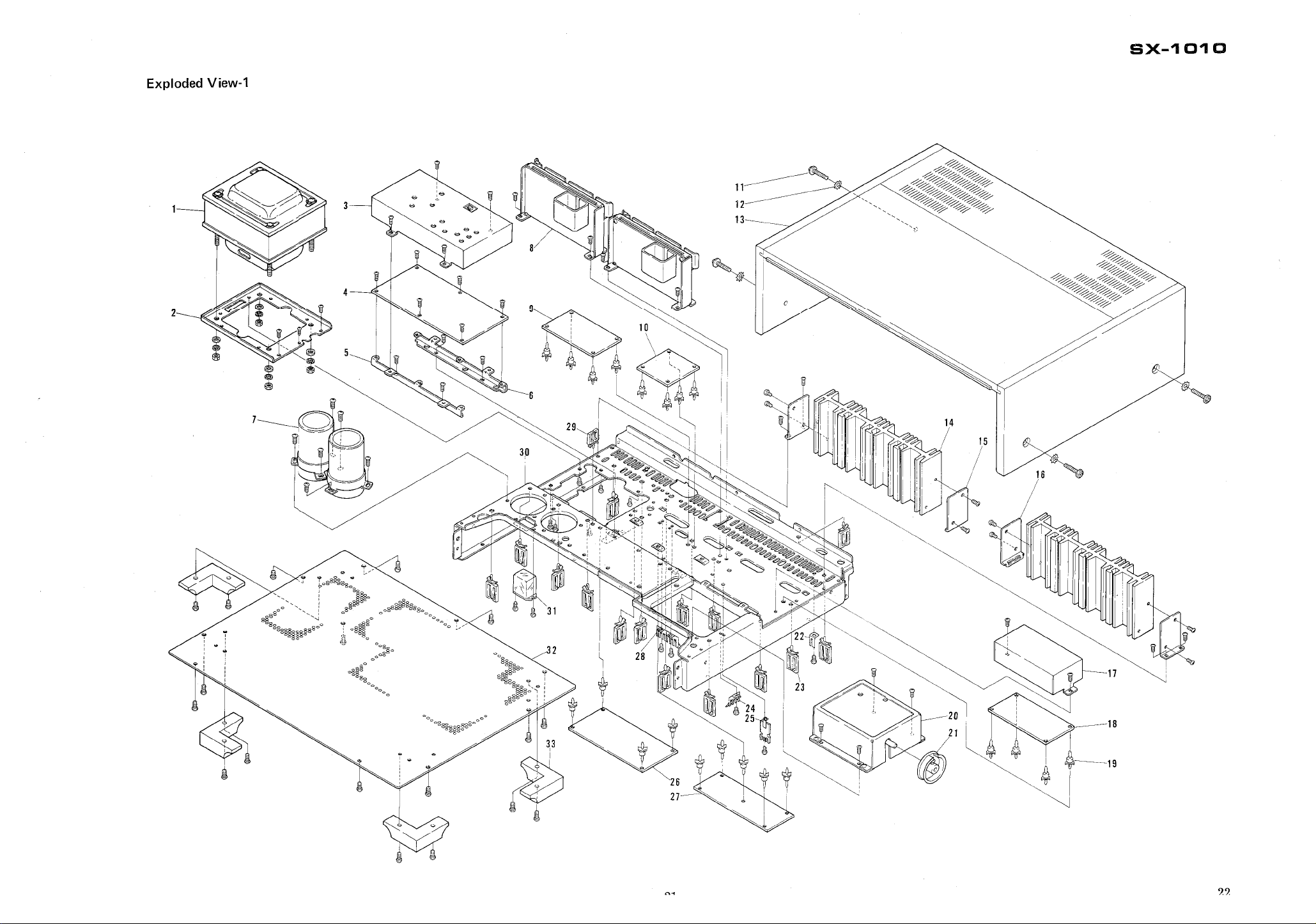
Exploded View-
eX-
1 0'1 0
For KCU model
I -
3 J
'----
,."'
""""""",,"" " "" "" " "
~""
, y.- " . .,
".. :' " j
. + .. . :;;:,
~'. ",' " ~ .. .- .. . ~" . ' . '
,;
j ,
=- -
'" '
" '.
-!;';;;
',p.
;~~;;;-, ,~;,:;:~;,..
., ~
-€!
" ,-"
'== ' -.-~..
~~ ~~
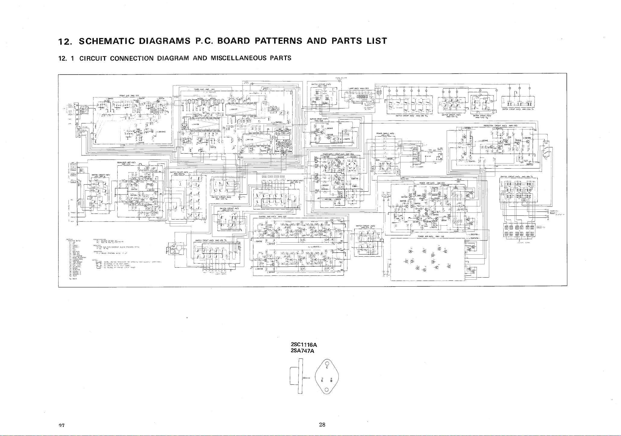
12.
SCHEMATIC DIAGRAMS P.
C. BOARD PATTERNS AND PARTS LIST
12. 1 CIRCUIT CONNECTION DIAGRAM AND MISCELLANEOUS
PARTS
I r "~
:tl
"'7' . "".'
A~.
--;;:, ""'A"
I:"
::",~ I
"'l
' J
rT:'b:c:~c-i
:'i
G8~
I '
=r;
"=r.~ 1'1'
-1-
, r
'1 (
~L 01 ~~. i
Jc.
I "'
1 ~
91,
~~I
;::' i
IJc'
h I
."c -
~~. I
'eM
r:-
, o
nL~;
rL I
-.J
2SC1116A
2SA747A
-0 0
II '
0 -0
ED .
' -f9
!2J-
r2-
I ',
t;L j
~~~~1f-bfd
')7
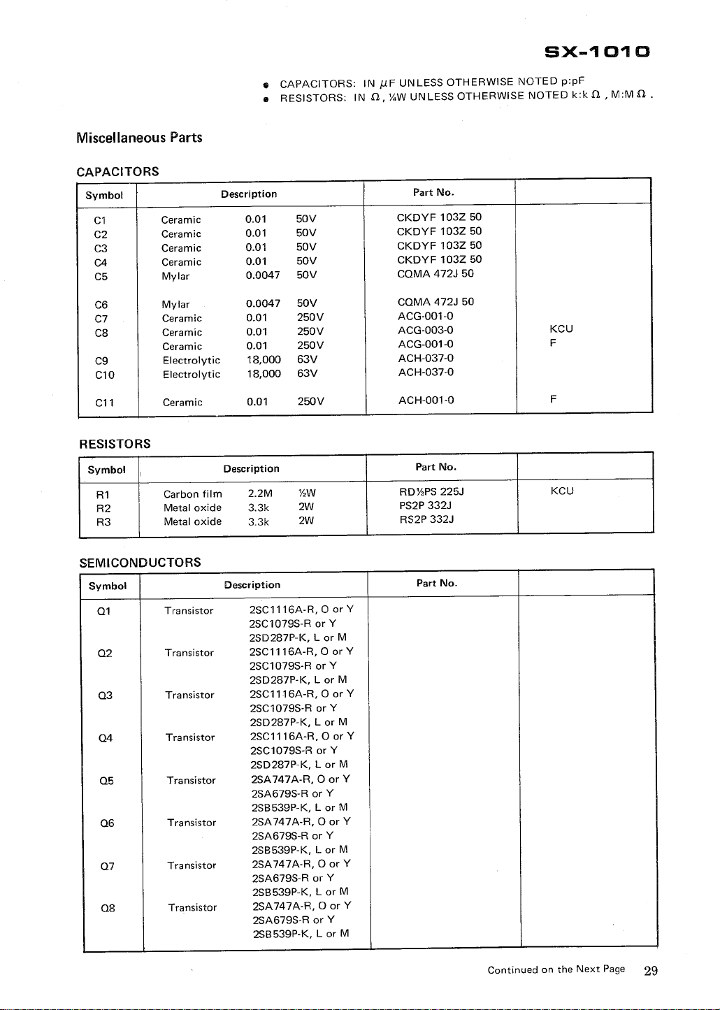
SX-
1 01 0
Miscellaneous Parts
CAPACITORS
Symbol
Ceramic
Ceramic
Ceramic
Ceramic
Mylar
Mylar
Ceramic
Ceramic
Ceramic
Electrolytic
C10
C11
RESISTORS
Symbol I
Electrolytic
Ceramic
Carbon film
Metal oxide
Metal oxide
. CAPACITORS:
Description
0047
0047
18,000
18,000
Description
RESISTORS: IN
50V
50V
50V
50V
50V
50V
250V
250V
250V
63V
63V
250V
'hW
IN J.1F UNLESS OTHERWISE NOTED p:pF
UNLESS OTHERWISE NOTED k:k
, y.W
Part No.
CKDYF 103Z 50
CKDYF 103Z 50
CKDYF 103Z 50
CKDYF 103Z 50
COMA 472J 50
COMA 472J 50
ACG-001-
ACG-003-
ACG-001-
ACH-037-
ACH-037-
ACH-001-
Part No.
RD'hPS 225J
PS2P 332J
RS2P 332J
KCU
KCU
M:M
SEMICONDUCTORS
Symbol
Transistor
Transistor
Transistor
Transistor
Transistor
Transistor
Transistor
Transistor
Description
2SC1116A-
2SC1079S-
2SD287P-
2SC1116A-
2SC1079S-
2SD287P-
2SC1116A-
2SC1079S-
2SD287P-
2SC1116A-
2SC1079S-
2SD287P-
2SA747A-
2SA679S-
2SB539P-
2SA747A-
2SA679S-
2SB539P-
2SA747A-
2SA679S-
2SB539P-
2SA747A-
2SA679S-
2SB539P-
Part No.
, 0 or Y
R or Y
, Lor M
OorY
R or Y
K, Lor M
, 0 or Y
R or Y
, L or M
, 0 or Y
R or Y
, L or M
, 0 or Y
R or Y
, Lor M
, 0 or Y
R or Y
, Lor M
, 0 or Y
R or Y
, Lor M
, 0 or Y
R or Y
, L or M
Continued on the Next Page
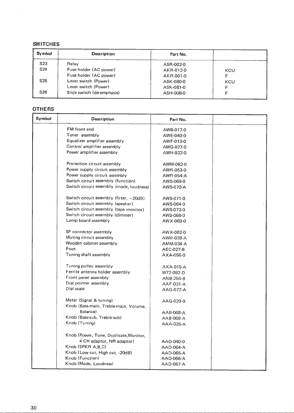
SWITCHES
Symbol
S23 Relay
S24
S25
S26
OTHERS
Symbol
Description
Fuse holder (AC power)
Fuse holder (AC power)
Lever switch (Power)
Lever switch (Power)
Slide switch (de-emphasis)
Description
, -
, -
Part No.
ASR-
002-
AKR- 12-
AKR-
001-
ASK-
080-
ASK-O81-
ASH-
008-
Part No.
KCU
KCU
FM front end
Tuner assembly
Equalizer amplifier assembly
Control amplifier assembly
Power amplifier assembly
Protection circuit assembly
Power supply circuit assembly
Power supply circuit assembly
Switch circuit assembly (function)
Switch circuit assembly (mode
Switch circuit assembly (filter
, loudness)
20dB)
Switch circuit assembly (speaker)
Switch circuit assembly (tape monitor)
Switch circuit assembly (dimmer)
Lamp board assembly
5P connector assembly
Muting circuit assembly
Wooden cabinet assembly
Foot
Tuning shaft assembly
Tuning pulley assembly
Ferrite antenna holder assembly
Front panel assembly
Dial pointer assembly
Dial scale
AWB-
017-
AWE-
040-
AWF-
013-
AWG-
027-
AWH-
032-
AWM-
062-
AWR-
053-
AWR-
054-
AWS-
069-
AWS-
070-
AWS-
071-
AWS-
064-
AWS-
072-
AWS-
068-
AWX-
069-
AWX-
062-
AWM-
039-
AMM-
O34-
AEC-
027-
AXA-
056-
AXA-
015-
W72-
092-
ANB-255-
AAF-
031-
AAG-
O72-
Meter (Signal & tuning)
Knob (Bass-main
Balance)
Knob (Bass-sub
Knob (Tuning)
Knob (Power
4 CH adaptor
Knob (SPKR A
Knob (Low cut
, Treble-main
, Treble-
, Tone
, Duplicate Monitor
, NR adaptor)
, High cut
Knob (Function)
Knob (Mode
, Loudness)
sub)
, Volume
20dB)
AAG-029-
AAB-068-
AAB-
069-
AAA-
026-
AAD-
040-
AAD-
O64-
AAD-
065-
AAD-
O66-
AAD-067-
 Loading...