

Page 1
STANDBY/
POWER ON
POWER
POWERED SPEAKER SYSTEM
S-W80S
THIS MANUAL IS APPLICABLE TO THE FOLLOWING MODEL(S) AND TYPE(S).
Type
MLXCN AC220-230V
Model
S-W80S
Power Requirement Remarks
ORDER NO.
RRV2407
CONTENTS
1. SAFETY INFORMATION
2. EXPLODED VIEWS AND PARTS LIST
3. SCHEMATIC DIAGRAM
4. PCB CONNECTION DIAGRAM
5. PCB PARTS LIST
6. ADJUSTMENT
PIONEER CORPORATION 4-1, Meguro 1-chome, Meguro-ku, Tokyo 153-8654, Japan
PIONEER ELECTRONICS SERVICE, INC. P.O. Box 1760, Long Beach, CA 90801-1760, U.S.A.
PIONEER EUROPE NV Haven 1087, Keetberglaan 1, 9120 Melsele, Belgium
PIONEER ELECTRONICS ASIACENTRE PTE. LTD. 253 Alexandra Road, #04-01, Singapore 159936
c
PIONEER CORPORATION 2000
...............................................
....................................................
......................................
................
.......................................
............................
12
12
2
3
6
8
7. GENERAL INFORMATION
7.1 DISASSEMBLY/ASSEMBLY
8. PANEL FACILITIES AND SPECIFICATIONS
................................
.......................
T – ZZV NOV. 2000 Printed in Japan
....
13
13
14
Page 2
S-W80S
1. SAFETY INFORMATION
This service manual is intended for qualified service technicians ; it is not meant for the casual do-ityourselfer. Qualified technicians have the necessary test equipment and tools, and have been trained
to properly and safely repair complex products such as those covered by this manual.
Improperly performed repairs can adversely affect the safety and reliability of the product and may
void the warranty. If you are not qualified to perform the repair of this product properly and safely, you
should not risk trying to do so and refer the repair to a qualified service technician.
WARNING
This product contains lead in solder and certain electrical parts contain chemicals which are known to the state of California to cause
cancer, birth defects or other reproductive harm.
NOTICE
(FOR CANADIAN MODEL ONLY)
Fuse symbols (fast operating fuse) and/or (slow operating fuse) on PCB indicate that replacement parts must
be of identical designation.
REMARQUE
(POUR MODÈLE CANADIEN SEULEMENT)
Les symboles de fusible (fusible de type rapide) et/ou (fusible de type lent) sur CCI indiquent que les pièces
de remplacement doivent avoir la même désignation.
Health & Safety Code Section 25249.6 – Proposition 65
(FOR USA MODEL ONLY)
1. SAFETY PRECAUTIONS
The following check should be performed for the
continued protection of the customer and service
technician.
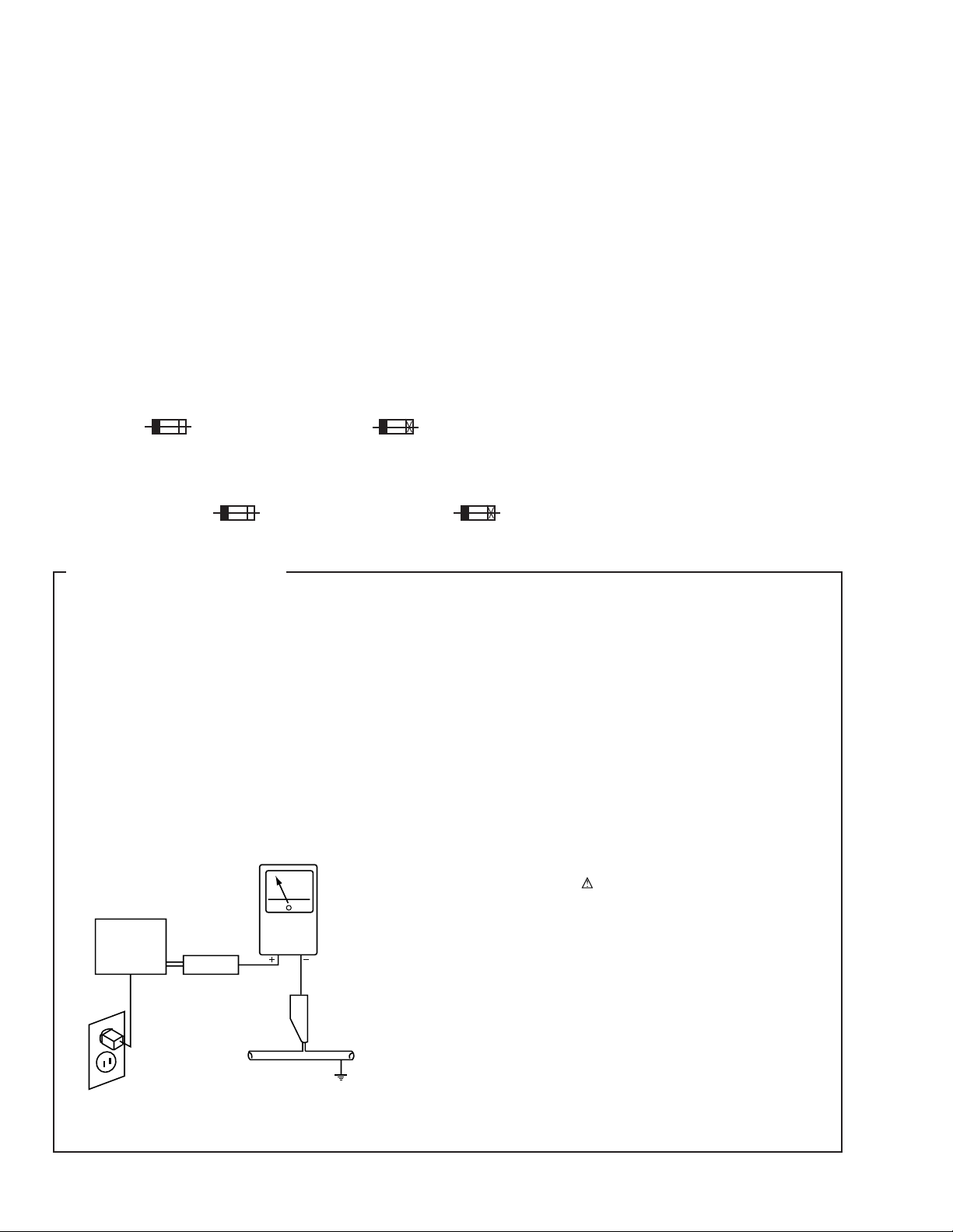
LEAKAGE CURRENT CHECK
Measure leakage current to a known earth ground (water
pipe, conduit, etc.) by connecting a leakage current tester
such as Simpson Model 229-2 or equivalent between the
earth ground and all exposed metal parts of the appliance
(input/output terminals, screwheads, metal overlays, control
shaft, etc.). Plug the AC line cord of the appliance directly
into a 120V AC 60Hz outlet and turn the AC power switch
on. Any current measured must not exceed 0.5mA.
Reading should
not be above
0.5mA
Earth
ground
Device
under
test
Also test with
plug reversed
(Using AC adapter
plug as required)
Test all
exposed metal
surfaces
Leakage
current
tester
ANY MEASUREMENTS NOT WITHIN THE LIMITS
OUTLINED ABOVE ARE INDICATIVE OF A POTENTIAL
SHOCK HAZARD AND MUST BE CORRECTED BEFORE
RETURNING THE APPLIANCE TO THE CUSTOMER.
2. PRODUCT SAFETY NOTICE
Many electrical and mechanical parts in the appliance
have special safety related characteristics. These are
often not evident from visual inspection nor the protection
afforded by them necessarily can be obtained by using
replacement components rated for voltage, wattage, etc.
Replacement parts which have these special safety
characteristics are identified in this Service Manual.
Electrical components having such features are identified
by marking with a
in this Service Manual.
The use of a substitute replacement component which does
not have the same safety characteristics as the PIONEER
recommended replacement one, shown in the parts list in
this Service Manual, may create shock, fire, or other hazards.
Product Safety is continuously under review and new
instructions are issued from time to time. For the latest
information, always consult the current PIONEER Service
Manual. A subscription to, or additional copies of, PIONEER
Service Manual may be obtained at a nominal charge from
PIONEER.
on the schematics and on the parts list
AC Leakage Test
2
Page 3
2. EXPLODED VIEWS AND PARTS LIST
NOTES:• Parts marked by "NSP" are generally unavailable because they are not in our Master Spare Parts List.
The mark found on some component parts indicates the importance of the safety factor of the part.
•
Therefore, when replacing, be sure to use parts of identical designation.
Screws adjacent to mark on the product are used for disassembly.
•
S-W80S
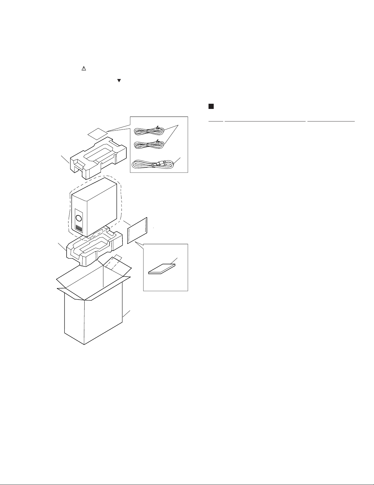
2.1 PACKING
3
3
PACKING PARTS LIST
Mark No. Description Part No.
1
2
4
1 Speaker Cord 305131
2 RCA Pin Cord 305232
3 Cushion 305239
4 Operating Instructions 310235
(English, Chinese)
5 Packing Case 310242
5
3
Page 4
S-W80S
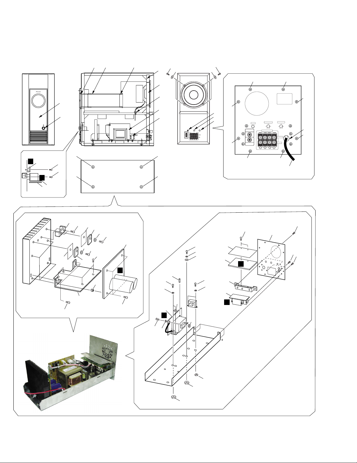
2.2 EXTERIOR
(Front)
18
D
E
11
42 47 48
(Side)
43
6
(Rear)
37
37
6
5
5
38
44
46
30
39
STANDBY/
POWER ON
POWER
32
(Bottom)
31
32
50 200
Hz
LINE LEVEL
SPEAKER LEVEL
OUTPUT
LR
OUTPUT
INPUT
LINE LEVEL
INPUT
- -
+ +
1
1
32
32
40
41
41
5
SPEAKER LEVEL
LR
OUTPUT
5
+ +
5
INPUT
- -
5
35
5
17
5
27
9
45
23
23
45
28
33
23
33
23
2
29
25
C
13
14
24
34
7
22
37
26
F
4
36
19
24
34
37
23
33
12
15
8
16
A
21
10
B
3
3
23
19
20
20
4
Page 5

EXTERIOR PARTS LIST
Mark No. Description Part No.
1 Screw (PW SW,LED) BBZ26P080FMC
2 Screw (HS Holder) BBZ30P080FMC
3 Screw
4 Screw (GND Cord) BMZ30P080FMC
5 Screw (Rear Panel) BYC30P100FZK
6 Screw (Speaker) BYC40P200FZB
7 HS Holder E305002
8 PCB Holder E305003
9 TS Holder E305005
10 Rear Panel E305006B
11 Insulation Sheet (PWS ASSY) E305033
12 Shield Sheet (HEAD ASSY) E305034
13 Spacer (Heat Sink) E305518
14 Fuse (FU501 : 1.6A250V) FSE1.6A250
15 HEAD ASSY HEAD1002
16 INPUT ASSY IN1002
17 Cord Bush (Power Cord) KBUF41
18 LED ASSY LED1002
19 Nut (GND Cord,Sub PWR. T.) NB30FMC
20 Nut (Main PWR. T.) NB40FMC
(Terminal,Jack,PCB Hold)
BBZ30P100FZB
S-W80S
21 Screw (HEAD ASSY) PBZ26P080FZK
22 Screw (POA ASSY) PMZ30P060FMC
23 Screw (TR,TS,HS,Sub PWR. T.) PMZ30P100FMC
24 Screw (Main PWR. T.) PMZ40P120FMC
25 POA ASSY POA1002
28 Transistor (Q111) Q2SC51980
29 Transistor (Q112) Q2SA19410
30 Power Transformer (T501)(Main) T0660
31 Power Transformer (T502)(Sub) T1120
35 AC Power Cord WPPHP-205
26 POS ASSY POS1002E
27 PWS ASSY PWS1002
32 Screw (Network Assy) TMZ40P300FZB
33 Washer (Tr,Sub PWR T.) WC30FMC
34 Washer (Main PWR T.) WC40FMC
36 Washer (GND Cord) WS30FMC
37 Washer (Main PWR. T.) WS40FMC
38 Speaker 305113
39 Power Switch Knob 305121
40 Phase Switch Knob 305122
41 Volume Knob 305123
42 Packing (Front Panel) 305212
43 Packing (Speaker) 305216
44 Cord Bush (SP Cord) 926209
45 TR Insulating Sheet ZCW-4
46 Front Panel 305109
47 Paper Duct 305211
48 Duct Ring 305110
5
Page 6

1
23
S-W80S
3. SCHEMATIC DIAGRAM
INPUT, HEAD, POA, LED, PWS and POS ASSYS
4
A
INPUT
ASSY
(IN1002)
B
C
PWS ASSY
(PWS1002)
D
AC220~230V 50/60Hz
T0660
250V1.6A
D5SBA60
POS ASSY
(POS1002E)
NOTE FOR FUSE REPLACEMENT
6
A
B C E F
1234
CAUTION
FOR CONTINUED PROTECTION AGAINST RISK OF FIRE.
REPLACE ONLY WITH SAME TYPE AND RATINGS ONLY.
Page 7

5
678
S-W80S
Note : When ordering service parts, be sure to refer to "EXPLODED VIEWS and PARTS LIST" or "PCB PARTS LIST".
: AUDIO SIGNAL ROUTE
HEAD ASSY
(HEAD1002)
1. Resistor
Unit : Unmarked K : kΩ, M : MΩ
Ratings : Unmarked 1/16W
Accuracy : Unmarked ± 5% (J)
2. Capacitor
Unit : Unmarked µF, p : pF
LED ASSY
(LED1002)
Display : Capacitor/Voltage
3. Voltage•Current
4. Others
indicates the signal route.
Be sure to use parts of identical designation at mark.
5. Switch
HEAD ASSY
SW ASSY
6. Parts sign
Film Capacitor with unmarked voltage 100V
Ceramic capacitor with unmarked voltage 100V
: Input and output voltage for rating output
: DC voltage at no signal input (V)
Inside ( ) is DC voltage (V) at rating output.
: DC current at no signal input
S1 : PHASE 0° –180°
VR1 : TURN OVER CONTROL
50Hz – 200Hz
VR2 : LEVEL
MIN – MAX
SW501 : POWER ON – OFF
Nonflammable resistor sign :
Nonflammable surfacing resistor sign :
Fusibel resistor sign :
Mylar film capacitor sign :
A
B
C
E.
LY.
POA ASSY
D
(POA1002)
ST90AR3V3
B C
5
6
7
D
8
7
Page 8

1
S-W80S
23
4
4. PCB CONNECTION DIAGRAM
A
NOTE FOR PCB DIAGRAMS :
1. Part numbers in PCB diagrams match those in the schematic
diagrams.
2. A comparison between the main parts of PCB and schematic
diagrams is shown below.
Symbol In PCB
Diagrams
B
3. The parts mounted on this PCB include all necessary parts for
several destinations.
For further information for respective destinations, be sure to
check with the schematic diagram.
4. View point of PCB diagrams.
BCE
BCE
D
Connector
Symbol In Schematic
Diagrams
BCEBCE
BCE
BCE
DGGSS
DGS
Capacitor
Part Name
Transistor
Transistor
with resistor
Field effect
transistor
Resistor array
3-terminal
regulator
SIDE A
B
CN3
4.1 INPUT ASSY
A
INPUT ASSY
P.C.Board
Chip Part
SIDE B
C
D
SIDE A
8
A
1234
Page 9

5
678
4.2 HEAD ASSY and LED ASSY
B
HEAD ASSY
S-W80S
A
Q2
Q1
Q5
IC2 Q6 IC1 IC3 Q4 IC4
B
C
D
D
LED ASSY
A
J3
CN505
F
C
J101
SIDE A
DB
5
6
7
8
9
Page 10

A
Q114
IC101
Q113
B
1
S-W80S
4.3 POA ASSY
C
POA ASSY
23
4
B
SP
C
Q109
Q108
Q106
Q103
Q110
Q107
Q104
Q105
Q101
Q102
F
CN504
D
CN6
B
10
SIDE A
C
1234
Page 11

5
Sub Power
Transformer
Sub Power
Transformer
AC Power Cord
Q503 Q502
Q501
POS ASSY
F
PWS ASSY
E
SIDE A
J103
C
J4
B
LIVE
NEUTRAL
4.4 POS ASSY and PWS ASSY
678
S-W80S
A
B
C
D
5
6
7
FE
8
11
Page 12

S-W80S
5. PCB PARTS LIST
NOTES:•Parts marked by "NSP" are generally unavailable because they are not in our Master Spare Parts List.
The mark found on some component parts indicates the importance of the safety factor of the part.
•
Therefore, when replacing, be sure to use parts of identical designation.
When ordering resistors, first convert resistance values into code form as shown in the following examples.
•
Ex.1 When there are 2 effective digits (any digit apart from 0), such as 560 ohm and 47k ohm (tolerance is shown by J=5%,
and K=10%).
560 Ω→56 × 10
47k Ω→47 × 10
0.5 Ω→R50 ..................................................................................... RN2H R 5 0 K
1 Ω→1R0 ..................................................................................... RS1P
Ex.2 When there are 3 effective digits (such as in high precision metal film resistors).
5.62k Ω→ 562 × 10
1
→ 561 ........................................................ RD1/4PU 5 6 1 J
3
→ 473 ........................................................ RD1/4PU 4 7 3 J
1 R 0
1
→ 5621 ...................................................... RN1/4PC 5 6 2 1 F
K
Mark No. Description Part No.
LSIT OF ASSEMBLIES
INPUT ASSY IN1002
HEAD ASSY HEAD1002
POA ASSY POA1002
PWS ASSY PWS1002
LED ASSY LED1002
POS ASSY POS1002E
A
INPUT ASSY
INPUT ASSY has no service part.
B
HEAD ASSY
RESISTORS
VR1 RK1632503B
VR2 RK1631203A
C
POA ASSY
SEMICONDUCTORS
IC102,IC103 IICP-F10
IC101 ITA7317P
Q101,Q102,Q114 Q2SA1048GR
Q103 Q2SA1049GR
Q110 Q2SA1358Y
Mark No. Description Part No.
D
LED ASSY
LED ASSY has no service part.
E
PWS ASSY
PWS ASSY has no service part.
F
POS ASSY
SEMICONDUCTORS
Q502 Q2SA1048GR
Q501 Q2SC2458GR
D501 D1B4B42
Q503 Q2SC2458GR
D502 D1N4002
RELAY
RY501 YG5PA-1
OTHERS
TH501 (Thermal Protector) ST90AR3U3
Q106 Q2SA9490
Q107 Q2SC22290
Q104,Q105,Q113 Q2SC2458GR
Q109 Q2SC3421Y
Q108 Q2SC982
D104 DD5SB40
D101 DMTZ3.9B
D105,D107 D1N4002
D102,D103 D1SS133
RELAY
RY101 YG5S-1
12
6. ADJUSTMENT
There is no information to be shown in this chapter.
Page 13

S-W80S
LED ASSY
PWS ASSY
When mounting, be sure to make the binding process
for the Power SW cord and LED cord by vinyl tape.
7. GENERAL INFORMATION
7.1 DISAASEMBLY
Removing the Amplifier Assy
1 ) The Amplifier Assy is attached to the cabinet by 4 external
screw 1. To detach it, pull down the subwoofer toward the
left side. Then unfasten those screws 1 (× 4)
Screw 1
2 ) Stand up the speaker again. After unfastening the rear panel
screw 2 (× 8), pull straight the Amplifier Assy toward back
about 13cm. Then remove the connecting cord of PWS Assy
and LED Assy. Next, pull out the Amplifier Assy and remove
the speaker cords.
SPEAKER LEVEL
- -
2
2
LR
OUTPUT
INPUT
2
2
2
2
2
+ +
2
Rear Panel
3 ) The PWS Assy and LED ASSY is attached to the front panel by
each 2 screws. To detach them, remove the Amplifier Assy
first. Then unfasten each screws from the cabinet back side.
Removing the Subwoofer
1 ) The speaker element is attached to the back board by 4 external
screws 3 and washers. To detach it, unfasten those screws and
washers.
2 ) When attaching the speaker, face its terminal downward.
(Screws must be used with washers.)
3
3
3
3
Amplifier Assy
When mouting the Amplifier Assy, be sure to
make the binding process for the speaker cord,
power SW cord, and LED cord by the binder.
50 200
Hz
LINE LEVEL
SPEAKER LEVEL
OUTPUT
LR
OUTPUT
INPUT
LINE LEVEL
INPUT
- -
+ +
Removing the Front Panel
The front panel is attached to the baffle by press-fitting.
To detach it, pry it open by inserting a flat blade screwdriver
into lower side.
13
Page 14

S-W80S
8. PANEL FACILITIES AND SPECIFICATIONS
FRONT PANEL
STANDBY/
POWER ON
POWER
1 Power Indicator (STANDBY/POWER ON)
When power is switched on, the power indicator lights green. If
no signal is present for more than 8 minutes, the subwoofer
automatically revents to standby mode and the power indicator
lights red. If, subsequently, a signal is received, power
automatically comes back on and the power indicator lights
green.
* If you not using the unit for an extended period of time,
please switch off using the power switch, and make sure that
the power indicator goes out.
1
2
REAR PANEL
TURNOVER LEVELPHASE
— 0˚ _ 180˚
50 MIN MAX200
LINE LEVEL
OUTPUT
4
5
LINE LEVEL
INPUT
6 Turnover knob (TURNOVER)
Sets the high limit of the frequency played back by the
subwoofer.
• Setting Criteria
50Hz................ when the diameter of the left/right speakers
is 20 cm or more.
100Hz.............. when the diameter of the left/right speakers
is 10-25 cm.
200Hz.............. when the diameter of the left/right speakers
is 12 cm or less.
Hz
SPEAKER LEVEL
- -
+ +
LR
OUTPUT
INPUT
6
73
8
9
2 Power Indicator (STANDBY/POWER ON)
When pressed, power is turned ON; when pressed again, power
is turned OFF.
3 Phase Switch (PHASE — 0° / _ 180°)
When depressed (_ 180º), the output phase becomes the
reverse of the input signal, and when raised (— 0º), it is in the
same phase as the input signal.
• Normally, the switch is set to (— 0º).
But when the sound connection between the subwoofer and
the left and right speakers sounds unnatural, try switching to
180º and set the switch in the position where the sound is
natural.
4 Line Level Output terminal (LINE LEVEL OUTPUT)
Used for connection other equipment through the amplifier.
5 Line Level Input terminal (LINE LEVEL INPUT)
Connectors to the stereo amplifier's SUBWOOFER PRE-OUT
terminal, with the specially provided RCA plug cord.
7 Level knob (LEVEL)
Sets the subwoofer volume.
• Turn the knob slowly from the MIN position.
• With the unit, the bass level can be independently set, so do
not turn up the bass on the stereo amplifier.
8 Speaker Level Output terminals
(SPEAKER LEVEL OUTPUT)
When the speakers output terminals on the stereo amplifier are
connected to this unit's SPEAKER LEVEL INPUT terminals 9
and used as the unit's input signal, these terminals are used to
connected the left and right speakers via the unit.
9 Speaker Level Input terminals
(SPEAKER LEVEL INPUT)
Connect to the speakers output terminal on the stereo amplifier,
with the specially provided speaker cords.
14
Page 15

SPECIFICATIONS
Cabinet .......................... Floor type with bass-reflex system
Speaker (Magnetically shielded type) ........ 16cm cone type
Power Amplifier
Continuous Power Output (RMS)...... 80W/8Ω (30-200Hz)
Total Harmonic Distortion ............................................. 0.5%
Above specifications are for when power supply is 230V.
•
(30-200Hz, 8Ω, 20W)
Input (sensitivity at 100Hz/impedance)
SPEAKER LEVEL................................... 1.6V+1.6V/15kΩ)
(both channels in-phase)
LINE LEVEL (RCA jack) ............................... 160mV/50kΩ)
Turnover Frequency ....... 50-200Hz (continuously variable)
Outline Dimensions ............190(W) × 420(H) × 430 (D) mm
Weight (without package) ........................................... 12.6kg
Power Requirements .......................... 220-230V ~, 50-60Hz
Power Consumption ....................................................... 70W
Power Consumption in Standby mode............................ 1W
Accessories
Speaker cords.......................................................................2
RCA plug cord.......................................................................1
Operating instructions .......................................................... 1
S-W80S
Note:
Specifications and design subject to possible modification
without notice,due to improvements.
Accessories
• Speaker Cord ×2
305131 (L=3m)
• RCA Pin Cord ×1
305232 (L=3m)
15
 Loading...