


ORDER No.AD0109126C8
Portable MD Recorder
SJ-MR220
MD unit: RAE1640Z-M Mechanism Series
|
|
|
Colour |
|
(S) |
................... |
Silver Type |
(W) |
..................White Type [(GH) area only.] |
||
|
|
|
Areas |
|
EB................... |
|
Great Britain. |
|
................... |
EG |
Europe. |
|
GCS ................ |
Singapore, Malaysia. |
|
|
GH................... |
|
Hong Kong. |
1
SPECIFICATIONS
 Audio
Audio
System:
Laser:
Sampling frequency:
Coding:
No. of channels:
Frequency response:
Wow and flutter:
 General
Input terminal
OPT/LINE IN jack
Impedance:
Input level:
MIC jack
Impedance:
Input level:
Output terminal
Output Jack:
Power output:
Power supply
Specifications
MiniDisc digital audio system Semiconductor laser (=780 nm) 44.1 kHz
Adaptive Transform Acoustic Coding (ATRAC / ATRAC3)
2 (left and right, stereo)
1 (monaural)
20 Hz-20 kHz (+0 dB, -8dB) Below measurable limit
22k 
SENS H: 178mV SENS L: 500mV
600 
SENS H: 0.4mV SENS L: 2.5mV
Phones, 22  3.5 mW+3.5 mW
2

Rechargeable battery: DC 1.2V
(included rechargeable battery)
DC 1.5V (One LR6, AA, UM-3 battery) DC 1.8V (included AC adaptor)
78.2x71.6x16.0 mm 80.4x74.1x18.3 mm
Weight: 115 g (with battery)
88 g (without battery)
 Play time
(When used in hold mode, at 25°C, on a flat, stable surface) Battery type: Play time Record time Rechargeable
Normal:
LP2:
LP4:
Panasonic alkaline Normal:
LP2:
LP4:
Both together Normal
LP2:
LP4:
Notes:
-The play time may be less depending on the operating conditions.
-Specifications are subject to charge without notice. Weight and dimensions are approximate.
 2001 Matsushita Electric Industrial Co., Ltd. All rights reserved. Unauthorized copying and distribution is a violation of law.
3
1. Accessories
- Rechargeable battery................................ |
.............1pc. |
(RP-BP62EYD) |
|
- External battery case............................................... |
1pc. |
(RFA1537-S2) |
|
- Carrying case......................................................... |
1pc. |
(RFC0069-H) |
|
- Stereo earphones.................................................. |
1pc. |
(L0BAB0000162) |
|
- Connection cable.................................................. |
1pc. |
(K2KA39B00001) |
|
For EB area |
|
- AC adaptor............................................................. |
1pc. |
(RFEA003B-S) |
|
For EG, GCS areas |
|
- AC adaptor............................................................. |
1pc. |
(N0JCAD000001) |
|
For GH area |
|
- AC adaptor............................................................. |
1pc. |
(RFEA004H-S) |
|
- Wired remote control............................................. |
1pc. |
(N2QCBD000012) |
|
For EB, EG, GCS areas |
|
- Wired remote control............................................ |
1pc. |
(N2QCBD000013) |
|
2. Precation of Laser Diode |
|
4

3.Operating Instructions
4.Handling Precautions for Traverse Deck
The laser diode in the traverse deck (optical pickup) may break down due to potential difference caused by static electricity of clothes or human body.
So, be careful of electrostatic breakdown during repair of the traverse deck (optical pickup).
5
4.1. Handling the traverse deck (optical pickup)
1.The traverse deck (optical pickup) is an extremely high-precision construction and must not be subjected to impact, excessive vibration, or other types of rough handling.
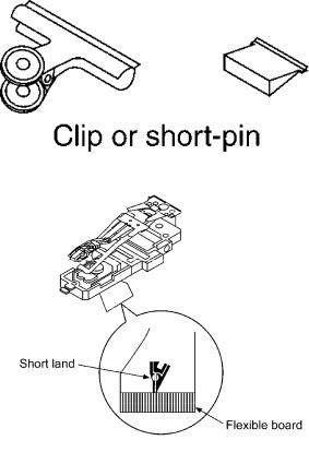
2.In order to prevent static electricity damage to the laser diode, use a short pin or similar tool to short the optical pickup’s flexible circuit boards after they have been disconnected from the main circuit board. (as shown in Fig. 1)
3.Handle the flexible circuit boards with care; excessive force could cause them to be broken.
4.Do not turn the pre-set variable resistor (for adjustment of the laser power); it has been adjusted at the factory.
(as shown in Fig. 2)
Fig. 1
Fig. 2
4.2. Grounding for electrostatic breakdown prevention
6
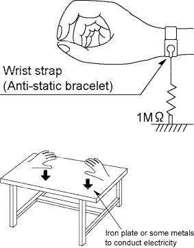
1.Human body grounding
Use the anti-static wrist strap to discharge the static electricity from your body. (as shown in Fig. 3)
2.Work table grounding
Put a conductive material (sheet) or steel sheet on the area where the traverse deck (optical pickup) is placed, and ground the sheet. (as shown in Fig. 4)
Caution
The static electricity of your clothes will not be grounded through the wrist strap.
So, take care not to let your clothes touch the traverse deck (optical pickup).
Fig. 3
Fig. 4
5. Operation Checks and Component Replacement
Procedures
-This section describes procedures for checking the operation of the major printed circuit boards and replacing the main components.
7
-For reassembly after operation checks or replacement, reverse the respective procedures. Special reassembly procedures are described only when required.
-After replacing the main components (optical pickup or traverse motor, etc.) of mechanism unit block, change to the adjust mode, and then perform the “ROM/RAM auto-adjustment”.
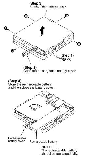
5.1. Checking for the main P.C.B.
- Check the main P.C.B. (A side) as shown below.
8
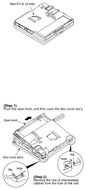
[Checking for the main P.C.B. (B side)]
-Each parts on main P.C.B. (B side) can not be checkesd directly, however, for the checking of main component parts on P.C.B., refer to the “Checking procedures of main components parts on the main P.C.B. (B side).
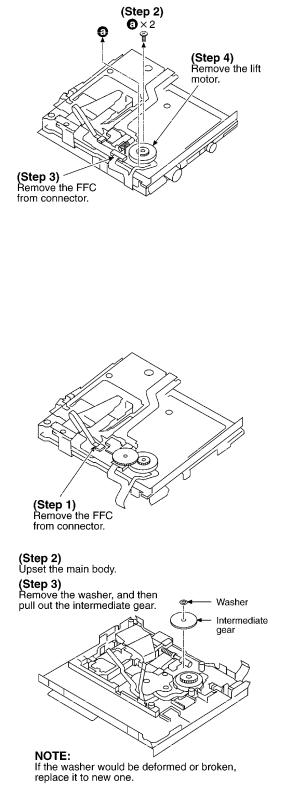
5.2. Replacement for the intermediate cabinet - Follow the (Step 1) - (Step 3) of item 5.1.
9
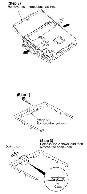
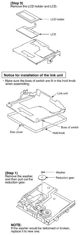
5.3. Replacement for the open knob and lock unit
-Follow the (Step 1) - (Step 3) of item 5.1.
-Follow the (Step 1) - (Step 3) of item 5.2.
5.4. Replacement for the traverse motor - Follow the (Step 1) - (Step 3) of item 5.1.
10
11
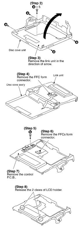
5.5. Replacement for the LCD
-Follow the (Step 1) - (Step 3) of item 5.1.
-Follow the (Step 1) - (Step 3) of item 5.2.
12
13
5.6. Replacement for the lift motor
-Follow the (Step 1) - (Step 3) of item 5.1.
-Follow the (Step 1) - (Step 3) of item 5.2.
-Follow the (Step 1) of item 5.5.
14
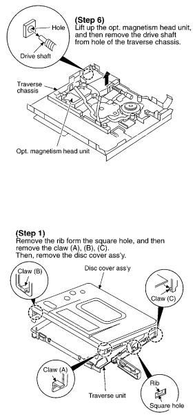
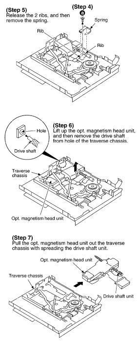
5.7. Replacement for the optical pickup
-Follow the (Step 1) - (Step 3) of item 5.1.
-Follow the (Step 1) - (Step 3) of item 5.2.
-Follow the (Step 1) - (Step 4) of item 5.4.
-Follow the (Step 1) of item 5.5.
15
16
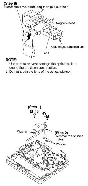
5.8. Replacement for the spindle motor
-Follow the (Step 1) - (Step 3) of item 5.1.
-Follow the (Step 1) - (Step 4) of item 5.4.
6. Measurements and Adjsutments
Note:
After replacing the main components (optical pickup or traverse motor, etc.) of mechanism unit block, change to the adjust mode, and then perform the “laser power adjustment”, “off-set autoadjustment” and “playback-only disc/magneto-optical disc auto-adjustment”.
6.1. Instruments to prepare
1. Playback-only disc (Test disc RFKV0006)
17
2.Commercially available recordable disc (fully recorded with music) (magneto-optical disc)
3.Laser power meter (LE8010 or compatible meter)
4.Remote controller
Note:
For use of MD cartridge type laser power meter, remove the intermediate cabinet before perform the laser power adjustment (as for the method of disassembly, refer to “5. Operation checks and main component replacement procedures”.).
6.2. Laser power adjustment, Playback-only disc/magneto-optical disc autoadjustment
6.2.1. Enter the adjustment mode
1.Set the battery and connect the remote controller.
2.Turn off the power, and switch main unit’s HOLD switch off.
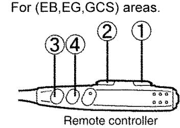
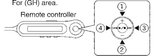
3.Press the buttons of the remote controller in order from 1 to 4 [ for
(EB, EG, GCS) areas, refer to Fig. 5. For (GH) area , refer to Fig. 6.]
Fig. 5
Fig. 6
18
4.When the adjustment mode is activated, “T0E1” or “T0E2” will be displayed on the LCD of remote controller and unit [(EB, EG, GCS) areas are displayed only unit]. After “T0E1” or “T0E2” is displayed, select the desired adjustment item with the button or
  button of the remote controller. (If it is not displayed, perform the procedures written above again.)
Adjustment mode
Adjustment mode |
Display |
Laser power adjustment |
T0** |
Off-set automatic adjustment |
T1** |
Magneto-optical disc automatic adjustment |
T2** |
Playback-only disc automatic adjustment |
T3** |
Automatic adjustment value check |
T4** |
EFM jitter meajurement |
T5** |
REC jitter meajurement |
T6** |
Area setting |
T7** |
Open |
T8** |
Error rate measurement (double velocity) |
T9** |
Open |
TA** |
ROM collection check sum |
TB** |
DRAM check |
TC** |
Reliability test |
TD** |
Tilt measurement (disc middle speed) |
TE** |
PWB inspection (audio test) |
TF** |
*In the display of T0** ~ TF** shown above, you must adjust T0**, T1**, T2** and T3**. You must perform the adjustment by observing the order T0**  T1**
T1**  T2**
T2**  T3**.
T3**.
19
 Loading...