


SFCRW-240-LS
Table of contents
 Loading...
ORDER NO.
PIONEER CORPORATION 4-1, Meguro 1-chome, Meguro-ku, Tokyo 153-8654, Japan
PIONEER ELECTRONICS (USA) INC. P.O. Box 1760, Long Beach, CA 90801-1760, U.S.A.
PIONEER EUROPE NV Haven 1087, Keetberglaan 1, 9120 Melsele, Belgium
PIONEER ELECTRONICS ASIACENTRE PTE. LTD. 253 Alexandra Road, #04-01, Singapore 159936
PIONEER CORPORATION 2004
RRV2923
S-FCRW240L-S
HOME THEATER LOUDSPEAKER SYSTEM
S-FCRW240L-S
POWERED SUBWOOFER
S-W240L-S
THIS MANUAL IS APPLICABLE TO THE FOLLOWING MODEL(S) AND TYPE(S).
Model Type Porew Requirement REMARKS
S-FCRW240L-S
S-W240L-S
KUXJI AC120V
KUXJI/CA AC120V
Speaker System
Powered Subwoofer of S-FCRW240L-S
For details, refer to "Important symbols for good services".
T-ZZV MAR. 2004 printed in Japan
1234
SAFETY INFORMATION
A
This service manual is intended for qualified service technicians; it is not meant for the casual
do-it-yourselfer. Qualified technicians have the necessary test equipment and tools, and have been
trained to properly and safely repair complex products such as those covered by this manual.
Improperly performed repairs can adversely affect the safety and reliability of the product and may
void the warranty. If you are not qualified to perform the repair of this product properly and safely, you
should not risk trying to do so and refer the repair to a qualified service technician.
WARNING
B
This product contains lead in solder and certain electrical parts contain chemicals which are known to the state of California to
cause cancer, birth defects or other reproductive harm.
Health & Safety Code Section 25249.6 – Proposition 65
NOTICE
(FOR CANADIAN MODEL ONLY)
Fuse symbols (fast operating fuse) and/or (slow operating fuse) on PCB indicate that replacement
parts must be of identical designation.
REMARQUE
(POUR MODÈLE CANADIEN SEULEMENT)
C
Les symboles de fusible (fusible de type rapide) et/ou (fusible de type lent) sur CCI indiquent que
les pièces de remplacement doivent avoir la même désignation.
(FOR USA MODEL ONLY)
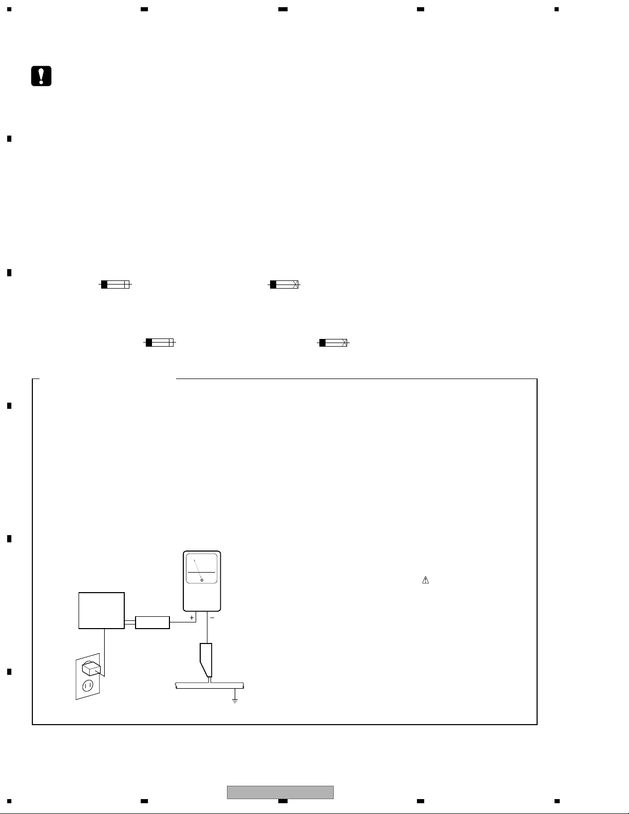
1. SAFETY PRECAUTIONS
The following check should be performed for the
continued protection of the customer and service
technician.
LEAKAGE CURRENT CHECK
Measure leakage current to a known earth ground
(water pipe, conduit, etc.) by connecting a leakage
D
E
current tester such as Simpson Model 229-2 or
equivalent between the earth ground and all exposed
metal parts of the appliance (input/output terminals,
screwheads, metal overlays, control shaft, etc.). Plug
the AC line cord of the appliance directly into a 120V
AC 60 Hz outlet and turn the AC power switch on. Any
current measured must not exceed 0.5 mA.
Reading should
not be above
0.5 mA
Earth
ground
Device
under
test
Also test with
plug reversed
(Using AC adapter
plug as required)
Test all
exposed metal
surfaces
Leakage
current
tester
AC Leakage Test
ANY MEASUREMENTS NOT WITHIN THE
LIMITS OUTLINED ABOVE ARE INDICATIVE
OF A POTENTIAL SHOCK HAZARD AND
MUST BE CORRECTED BEFORE RETURNING THE APPLIANCE TO THE CUSTOMER.
2. PRODUCT SAFETY NOTICE
Many electrical and mechanical parts in the appliance
have special safety related characteristics. These are
often not evident from visual inspection nor the
protection afforded by them necessarily can be obtained
by using replacement components rated for voltage,
wattage, etc. Replacement parts which have these
special safety characteristics are identified in this
Service Manual.
Electrical components having such features are
identified by marking with a
on the parts list in this Service Manual.
The use of a substitute replacement component which
does not have the same safety characteristics as the
PIONEER recommended replacement one, shown in the
parts list in this Service Manual, may create shock, fire,
or other hazards.
Product Safety is continuously under review and new
instructions are issued from time to time. For the latest
information, always consult the current PIONEER
Service Manual. A subscription to, or additional copies
of, PIONEER Service Manual may be obtained at a
nominal charge from PIONEER.
on the schematics and
F
2
1234
S-FCRW240L-S
5678
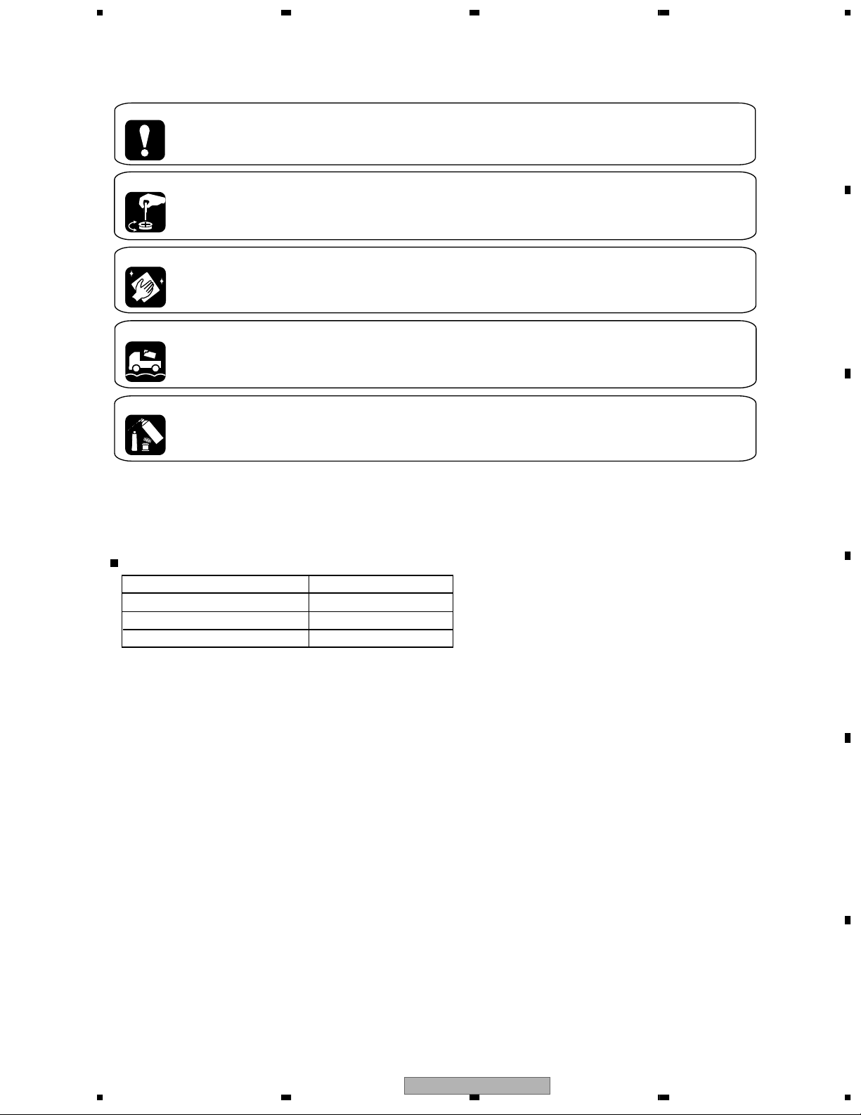
[ Important symbols for good services ]
In this manual, the symbols shown-below indicate that adjustments, settings or cleaning should be made securely.
When you find the procedures bearing any of the symbols, be sure to fulfill them:
A
1. Product safety
You should conform to the regulations governing the product (safety, radio and noise, and other regulations), and
should keep the safety during servicing by following the safety instructions described in this manual.
2. Adjustments
To keep the original performances of the product, optimum adjustments or specification confirmation is indispensable.
In accordance with the procedures or instructions described in this manual, adjustments should be performed.
3. Cleaning
For optical pickups, tape-deck heads, lenses and mirrors used in projection monitors, and other parts requiring cleaning,
proper cleaning should be performed to restore their performances.
B
4. Shipping mode and shipping screws
To protect the product from damages or failures that may be caused during transit, the shipping mode should be set or
the shipping screws should be installed before shipping out in accordance with this manual, if necessary.
5. Lubricants, glues, and replacement parts
Appropriately applying grease or glue can maintain the product performances. But improper lubrication or applying
glue may lead to failures or troubles in the product. By following the instructions in this manual, be sure to apply the
prescribed grease or glue to proper portions by the appropriate amount.For replacement parts or tools, the prescribed
ones should be used.
S-FCRW240L-S Speaker System
SATELLITE SPEAKER (Front) SMW1815
SATELLITE SPEAKER (Center) SMW1816
SATELLITE SPEAKER (Rear) SMW1817
POWERED SUBWOOFER S-W240L-S
C
D
56
S-FCRW240L-S
E
F
7
8
3

1234
CONTENTS
SAFETY INFORMATION ..................................................................................................................................... 2
A
B
1. SPECIFICATIONS ............................................................................................................................................5
2. EXPLODED VIEWS AND PARTS LIST ............................................................................................................ 6
2.1 PACKING ................................................................................................................................................... 6
2.2 SATELLITE SPEAKER(Front, Center, Rear) ............................................................................................. 8
2.3 POWERED SUBWOOFER........................................................................................................................ 9
2.4 POWER AMP SECTION.......................................................................................................................... 10
3. SCHEMATIC DIAGRAM .................................................................................................................................12
3.1 OVERALL BLOCK DIAGRAM.................................................................................................................. 12
3.2 AMP and OPERATION ASSYS................................................................................................................ 14
4. PCB CONNECTION DIAGRAM ..................................................................................................................... 16
4.1 AMP and OPERATION ASSYS................................................................................................................ 17
5. PCB PARTS LIST ...........................................................................................................................................19
6. ADJUSTMENT ............................................................................................................................................... 21
7. GENERAL INFORMATION............................................................................................................................. 22
7.1 DISASSEMBLY ........................................................................................................................................ 22
8. PANEL FACILITIES ........................................................................................................................................ 23
C
D
E
F
4
1234
S-FCRW240L-S
Note: Specifications and design subject to possible modification
without notice due to improvements.
* Measured pursuant to the Federal Trade Commission's Trade
Regulation rule on Power Output Claims for Amplifiers.
** Measured by Audio Spectrum Analyzer.
FRONT SPEAKERS
Enclosure ......................................... Closed box type
System .........
2-way magnetically shielded loudspeaker
System .........
1-way magnetically shielded loudspeaker
Drive Units
Tweeter ............................................. 1” ceramic type
Midrange ...................... 3” cone magnetically shielded
...................... 3” cone magnetically shielded
Nominal Impedance .......................................... 8 ohm
Frequency Range...................................... 100-20k Hz
Sensitivity spl @ 1m/ 2.83 V .............................. 85 dB
Maximum Input Power ...................................... 100 W
External Dimensions .............. 4 1/2” x 9 5/8” x 6 5/16”
WXHXD
Weight ...............................................................3.3 lbs
CENTER SPEAKER
Enclosure .......................................... Closed box type
Drive Units
Fullrange
Nominal Impedance ...........................................8 ohm
Frequency Range...................................... 100-20k Hz
Sensitivity spl @ 1m/ 2.83 V ............................... 85dB
Maximum Input Power ...................................... 100 W
External Dimensions .............11 7/8” x 4 1/2” x 3 1/8”
WXHXD
Weight ...............................................................1.9 lbs
1-way loudspeaker
REAR SPEAKER
Enclosure .......................................... Closed box type
System ...........................................
Drive Units
Fullrange ......................................................... 3” cone
Nominal Impedance ...........................................8 ohm
Frequency Range...................................... 100-20k Hz
Sensitivity spl @ 1m/ 2.83 V ............................... 85dB
Maximum Input Power ...................................... 100 W
External Dimensions .............4 1/2” x 6 1/8” x 3 1/8”
WXHXD
Weight ...............................................................1.2 lbs
POWERED SUBWOOFER
Enclosure ................... Floor standing bass-reflex type.
Speaker ................................................. 20 cm (8 inch)
Power Amplifier .............. Continuous Average Power
Output is 100 Watts* min, at
28 ohms from 20 Hertz to 200
Hertz with no more than 1%**
total harmonic distortion.
Input ...................................100 mV / 18 kΩ (at 60 Hz)
(Sensitivity at specified frequency/impedance)
Line level input(RCA - jack)
Crossover Frequency ........................................150 Hz
External Dimensions ........8 3/8” x 14 3/16” x 15 7/8”
WXHXD
Weight .............................................................17.8 lbs
Power Requirements......................... 120 VAC, 60 Hz
Power Consumption ................................ 64 W 130 VA
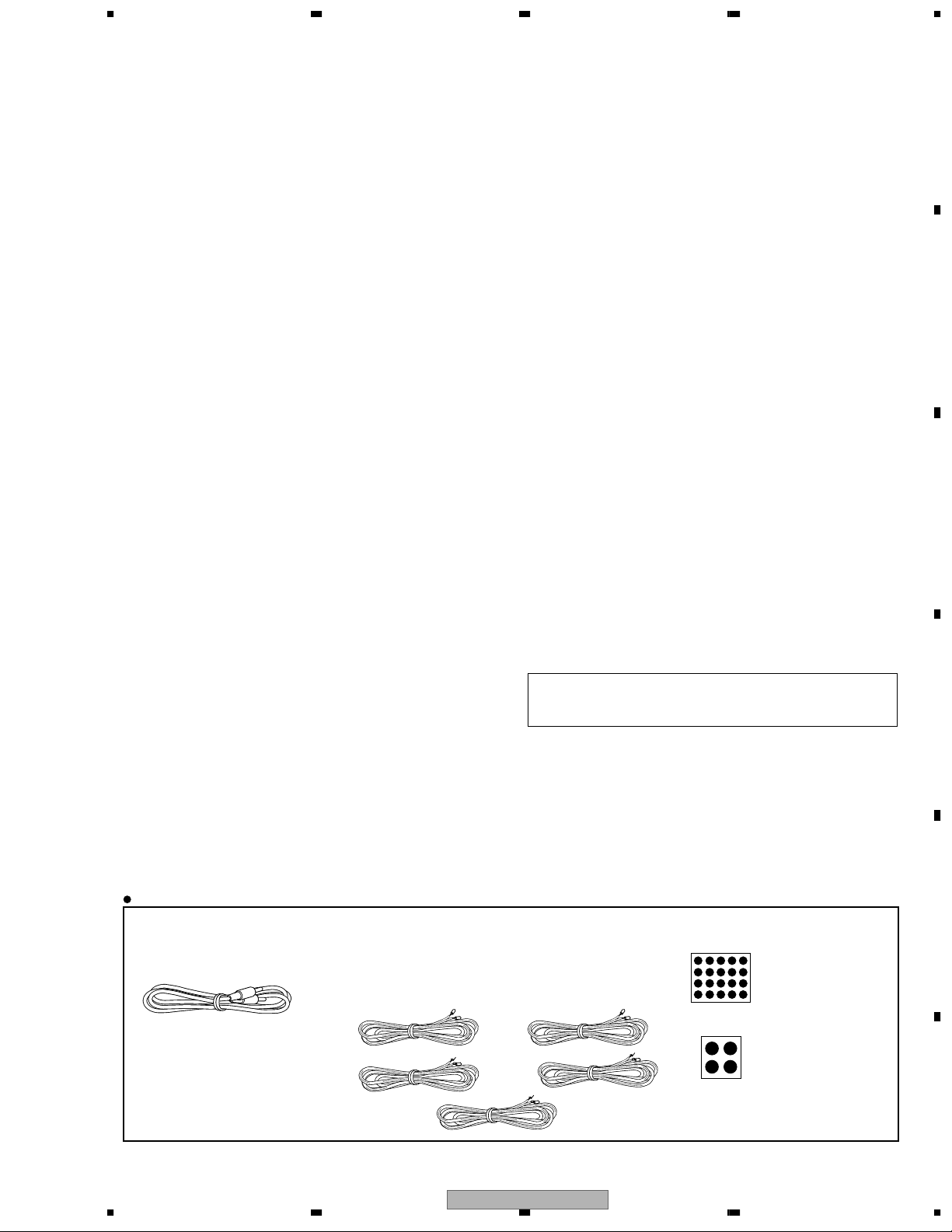
Accessories
• RCA cable
(SDE1032)
• Speaker wires ×3
(SDS1158 : 5m with red colored marker)
(SDS1159 : 5m with white colored marker)
(SDS1160 : 5m with green colored marker)
(SDS1161 : 10m with blue colored marker)
(SDS1162 : 10m with gray colored marker)
• Non skid pads
(SEC1635)
(for Satellite)
(SEC1563)
(for Subwoofer)
5678
1. SPECIFICATIONS
A
B
C
D
E
F
56
S-FCRW240L-S
7
8
5
1234
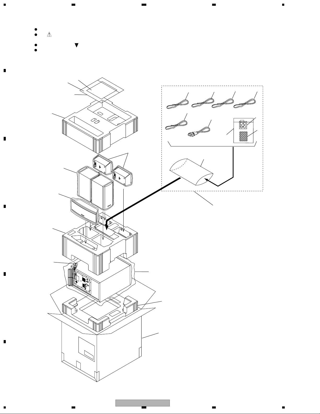
2. EXPLODED VIEWS AND PARTS LIST
NOTES:
A
2.1 PACKING
B
C
Parts marked by "NSP" are generally unavailable because they are not in our Master Spare Parts List.
The mark found on some component parts indicates the importance of the safety factor of the part.
Therefore, when replacing, be sure to use parts of identical designation.
Screws adjacent to mark on product are used for disassembly.
For the applying amount of lubricants or glue, follow the instructions in this manual.
(In the case of no amount instructions, apply as you think it appropriate.)
12
13
5
2
10
11
17
11
4
3
16
21
6
7
8
9
15
1
18
D
22
14
19
E
20
F
6
1234
S-FCRW240L-S

5678
PACKING parts List
No. Description Part No.
Mark
NSP 1 Accessories Set SME3464
2 RCA Cable SDE1032
3 Speaker Wire SDS1158
(5m with red colored marker for Front right)
4 Speaker Wire SDS1159
(5m with white colored marker for Front left)
5 Speaker Wire SDS1160
(5m with green colored marker for Front center)
6 Speaker Wire SDS1161
(10m with blue colored marker for Rear left)
7 Speaker Wire SDS1162
(10m with gray colored marker for Rear right)
8 Non Skid Pad (for Subwoofer) SEC1563
9 Non Skid Pad (for Satellite SP) SEC1635
10 Polyethylene Bag S0 SHL1343
11 Protection Sheet S3 SHC1806
12 Operating Instructions (English) SRB1333
NSP 13 Operating Instructions Assy SME3465
14 Protection Sheet S6 SHC1809
15 Protection Sheet S2 SHC1807
A
B
16 Protection Sheet S2 SHC1808
17 Top Protector SHA2429
18 Middle Protector SHA2430
19 Bottom Protector SHA2410
20 Packing Case SHG2546
21 Protection Sheet S3 SHC1811
22 Protection Sheet S1 SHC1802
C
D
E
56
S-FCRW240L-S
F
7
8
7
Loading...