

Page 1
PIONEER CORPORATION 4-1, Meguro 1-chome, Meguro-ku, Tokyo 153-8654, Japan
PIONEER ELECTRONICS (USA) INC. P.O. Box 1760, Long Beach, CA 90801-1760, U.S.A.
PIONEER EUROPE NV Haven 1087, Keetberglaan 1, 9120 Melsele, Belgium
PIONEER ELECTRONICS ASIACENTRE PTE. LTD. 253 Alexandra Road, #04-01, Singapore 159936
PIONEER CORPORATION 2003
This product does not finction properly when independent ; to avoid malfunctions, be
sure to connect it to the prescribed system component(s), otherwise damage may result
XV-DV830 RRV2817
S-DV830
S-DV830SW RRV2807
S-DV830ST
DVD/CD TUNER
SPEAKER SYSTEM
POWERED SUBWOOFER
SPEAKER SYSTEM
This manual
Component System
Service Manual Remarks
XV-DV99 RRV2792
S-DV99
S-DV99SW RRV2807
S-DV99ST
DVD/CD TUNER
SPEAKER SYSTEM
POWERED SUBWOOFER
SPEAKER SYSTEM
This manual
Component System
Service Manual Remarks
Surround
Front
Surround
Subwoofer
Front
Center
S-DV830
SPEAKER SYSTEM
S-DV830
S-DV99
THIS MANUAL IS APPLICABLE TO THE FOLLOWING MODEL(S) AND TYPE(S).
Model Type Power Requirement Model Type Power Requirement
S-DV830, S-DV830SW KUCXJI AC120V S-DV830ST XJI/UC ––––––––––
S-DV99, S-DV99SW MYXJI AC220-230V S-DV99ST XJI/EW ––––––––––
S-DV99, S-DV99SW NVXJI AC230V
S-DV99SW S-DV99ST
S-DV830SW S-DV830ST
ORDER NO.
RRV2807
For details, refer to "Important symbols for good services".
T-ZZE JULY 2003 printed in Japan
Page 2
1234
SAFETY INFORMATION
A
This service manual is intended for qualified service technicians; it is not meant for the casual
do-it-yourselfer. Qualified technicians have the necessary test equipment and tools, and have been
trained to properly and safely repair complex products such as those covered by this manual.
Improperly performed repairs can adversely affect the safety and reliability of the product and may
void the warranty. If you are not qualified to perform the repair of this product properly and safely, you
should not risk trying to do so and refer the repair to a qualified service technician.
WARNING
B
This product contains lead in solder and certain electrical parts contain chemicals which are known to the state of California to
cause cancer, birth defects or other reproductive harm.
Health & Safety Code Section 25249.6 – Proposition 65
NOTICE
(FOR CANADIAN MODEL ONLY)
Fuse symbols (fast operating fuse) and/or (slow operating fuse) on PCB indicate that replacement
parts must be of identical designation.
REMARQUE
(POUR MODÈLE CANADIEN SEULEMENT)
C
Les symboles de fusible (fusible de type rapide) et/ou (fusible de type lent) sur CCI indiquent que
les pièces de remplacement doivent avoir la même désignation.
(FOR USA MODEL ONLY)
1. SAFETY PRECAUTIONS
The following check should be performed for the
continued protection of the customer and service
technician.
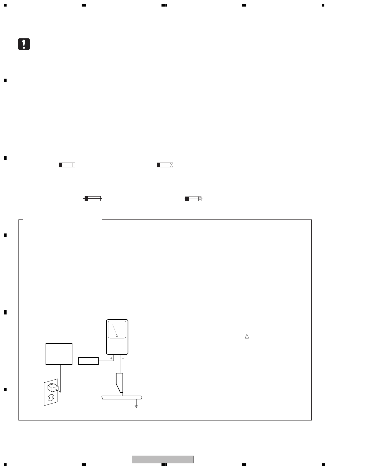
LEAKAGE CURRENT CHECK
Measure leakage current to a known earth ground
(water pipe, conduit, etc.) by connecting a leakage
D
E
current tester such as Simpson Model 229-2 or
equivalent between the earth ground and all exposed
metal parts of the appliance (input/output terminals,
screwheads, metal overlays, control shaft, etc.). Plug
the AC line cord of the appliance directly into a 120V
AC 60 Hz outlet and turn the AC power switch on. Any
current measured must not exceed 0.5 mA.
Reading should
not be above
0.5 mA
Earth
ground
Device
under
test
Also test with
plug reversed
(Using AC adapter
plug as required)
Test all
exposed metal
surfaces
Leakage
current
tester
AC Leakage Test
ANY MEASUREMENTS NOT WITHIN THE
LIMITS OUTLINED ABOVE ARE INDICATIVE
OF A POTENTIAL SHOCK HAZARD AND
MUST BE CORRECTED BEFORE RETURNING THE APPLIANCE TO THE CUSTOMER.
2. PRODUCT SAFETY NOTICE
Many electrical and mechanical parts in the appliance
have special safety related characteristics. These are
often not evident from visual inspection nor the
protection afforded by them necessarily can be obtained
by using replacement components rated for voltage,
wattage, etc. Replacement parts which have these
special safety characteristics are identified in this
Service Manual.
Electrical components having such features are
identified by marking with a
on the parts list in this Service Manual.
The use of a substitute replacement component which
does not have the same safety characteristics as the
PIONEER recommended replacement one, shown in the
parts list in this Service Manual, may create shock, fire,
or other hazards.
Product Safety is continuously under review and new
instructions are issued from time to time. For the latest
information, always consult the current PIONEER
Service Manual. A subscription to, or additional copies
of, PIONEER Service Manual may be obtained at a
nominal charge from PIONEER.
on the schematics and
F
2
1234
S-DV830
Page 3
5 678
[ Important symbols for good services ]
In this manual, the symbols shown-below indicate that adjustments, settings or cleaning should be made securely.
When you find the procedures bearing any of the symbols, be sure to fulfill them:
1. Product safety
You should conform to the regulations governing the product (safety, radio and noise, and other regulations), and
should keep the safety during servicing by following the safety instructions described in this manual.
2. Adjustments
To keep the original performances of the product, optimum adjustments or specification confirmation is indispensable.
In accordance with the procedures or instructions described in this manual, adjustments should be performed.
3. Cleaning
For optical pickups, tape-deck heads, lenses and mirrors used in projection monitors, and other parts requiring cleaning,
proper cleaning should be performed to restore their performances.
4. Shipping mode and shipping screws
To protect the product from damages or failures that may be caused during transit, the shipping mode should be set or
the shipping screws should be installed before shipping out in accordance with this manual, if necessary.
A
B
5. Lubricants, glues, and replacement parts
Appropriately applying grease or glue can maintain the product performances. But improper lubrication or applying
glue may lead to failures or troubles in the product. By following the instructions in this manual, be sure to apply the
prescribed grease or glue to proper portions by the appropriate amount.For replacement parts or tools, the prescribed
ones should be used.
C
D
56
S-DV830
E
F
7
8
3
Page 4

1234
CONTENTS
SAFETY INFORMATION..................................................................................................................................... 2
A
B
C
1. SPECIFICATIONS ............................................................................................................................................ 5
2. EXPLODED VIEWS AND PARTS LIST ............................................................................................................ 6
2.1 PACKING ................................................................................................................................................... 6
2.2 PRODUCT APPEARANCE SECTION [POWERD SUBWOOFER]........................................................... 8
2.3 AMPLIFIER ASSY ................................................................................................................................... 10
2.4 PRODUCT APPEARANCE SECTION [SPEAKER SYSTEM]................................................................. 12
3. BLOCK DIAGRAM AND SCHEMATIC DIAGRAM..........................................................................................14
3.1 BLOCK DIAGRAM AND OVERALL CONNECTION DIAGRAM .............................................................. 14
3.2 AF and TRADE 1 ASSY........................................................................................................................... 16
3.3 6CH AMP ASSY ...................................................................................................................................... 18
3.4 POWER ASSY......................................................................................................................................... 20
3.5 PRIMARY ASSY ...................................................................................................................................... 22
4. PCB CONNECTION DIAGRAM ..................................................................................................................... 24
4.1 AF and TRADE 1 ASSY........................................................................................................................... 24
4.2 6CH AMP ASSY ...................................................................................................................................... 28
4.3 POWER ASSY......................................................................................................................................... 30
4.4 PRIMARY ASSY ...................................................................................................................................... 34
5. PCB PARTS LIST ........................................................................................................................................... 36
6. ADJUSTMENT ............................................................................................................................................... 38
7. GENERAL INFORMATION ............................................................................................................................. 39
7.1 DIAGNOSIS ............................................................................................................................................. 39
7.1.1 PROTECTION CIRCUIT....................................................................................................................... 39
7.1.2 DISASSEMBLY ..................................................................................................................................... 41
7.2 IC ............................................................................................................................................................. 43
7.3 CLEANING............................................................................................................................................... 43
D
E
F
4
1234
S-DV830
Page 5
5 678
1. SPECIFICATIONS
Amplifier Section
Continuous Power (RMS) . . . . . 75 W / channel
. . . . . . . . . . . . . . . . . . . . . (1 kHz, THD 10%, 6 Ω)
Miscellaneous (MY and NV types)
Power Requirements
MY type . . . . . . . . . .AC 220–230 V, 50/60 Hz
NV type . . . . . . . . . . . . . . AC 230V, 50/60 Hz
Power Consumption . . . . . . . . . . . . . . . . . 163 W
Power Consumption
in standby mode . . . . . . . . . . . . . . . . . . . 0.48 W
Miscellaneous (KU type)
Power Requirements . . . . . . . . AC 120 V, 60 Hz
Power Consumption. . . . . . . . . . . . . . . . . 178 W
Power Consumption
in standby mode . . . . . . . . . . . . . . . . . . . 0.46 W
Powered subwoofer
(S-DV99SW)
Type . . . . . .Bass reflex floor type, antimagnetic
Speaker . . . . . . . . . . . . . . . . . .18 cm (cone type)
Nominal impedence. . . . . . . . . . . . . . . . . . . .6 Ω
Frequency range. . . . . . . . . . . . . . . 25 – 2300 Hz
Max. input . . . . . . . . . . . . . . . . . . . . 75 W (JEITA)
Dimensions . . . . 192 (W) x 436 (D) x 395 (H) cm
Weight . . . . . . . . . . . . . . . . . . . . . . . . . . . .12.5 kg
Powered subwoofer (S-DV830SW)
Type. . . . . . Bass reflex floor type, antimagnetic
Speaker. . . . . . . . . . . . . . . . . . 18 cm (cone type)
Nominal impedence . . . . . . . . . . . . . . . . . . . 6
Frequency range . . . . . . . . . . . . . . 25 – 2300 Hz
Max. input. . . . . . . . . . . . . . . . . . . . 75 W (JEITA)
Dimensions . . . .192 (W) x 436 (D) x 395 (H) cm
Weight . . . . . . . . . . . . . . . . . 12.5 kg / 27 lb. 9 oz
9
7
/16 (W) x 17 5/32 (D) x 15 9/16 (H) in.
Ω
Satellite Speaker System
(S-DV99ST)
Type Sealed, antimagnetic
Speaker . . . . . . . . . . . . . . . . . 8.7 cm (cone type)
. . . . . . . . . . . . . . . . . . . . . . . . 5.2 cm (cone type)
Nominal impedence. . . . . . . . . . . . . . . . . . . .6 Ω
Frequency range. . . . . . . . . . . . . .80 – 20,000 Hz
Max. input . . . . . . . . . . . . . . . . . . . . 75 W (JEITA)
Front / Surround speakers
Dimensions . . . . . 110 (W) x 59 (D) x 284 (H) cm
Weight . . . . . . . . . . . . . . . . . . . . . . . . . . . . .0.7 kg
Center speaker
Dimensions . . . . . 284 (W) x 59 (D) x 110 (H) cm
Weight . . . . . . . . . . . . . . . . . . . . . . . . . . . . .0.7 kg
Satellite Speaker System
(S-DV830ST)
Type Sealed, antimagnetic
Speaker. . . . . . . . . . . . . . . . . .8.7 cm (cone type)
. . . . . . . . . . . . . . . . . . . . . . . . .5.2 cm (cone type)
Nominal impedence . . . . . . . . . . . . . . . . . . . 6
Frequency range . . . . . . . . . . . . . 80 – 20,000 Hz
Max. input. . . . . . . . . . . . . . . . . . . . 75 W (JEITA)
Front / Surround speakers
Dimensions . . . . .110 (W) x 59 (D) x 284 (H) cm
Weight . . . . . . . . . . . . . . . . . . . 0.7 kg / 1 lb. 9 oz
Center speaker
Dimensions . . . . .284 (W) x 59 (D) x 110 (H) cm
Weight . . . . . . . . . . . . . . . . . . . 0.7 kg / 1 lb. 9 oz
•Specifications and design subject to
11
4
/32 (W) x 2 5/16 (D) x 11 3/16 (H) in.
3
/16 (W) x 2 9/32 (D) x 4 11/32 (H) in.
11
possible modification without notice, due
to improvements.
A
B
Ω
C
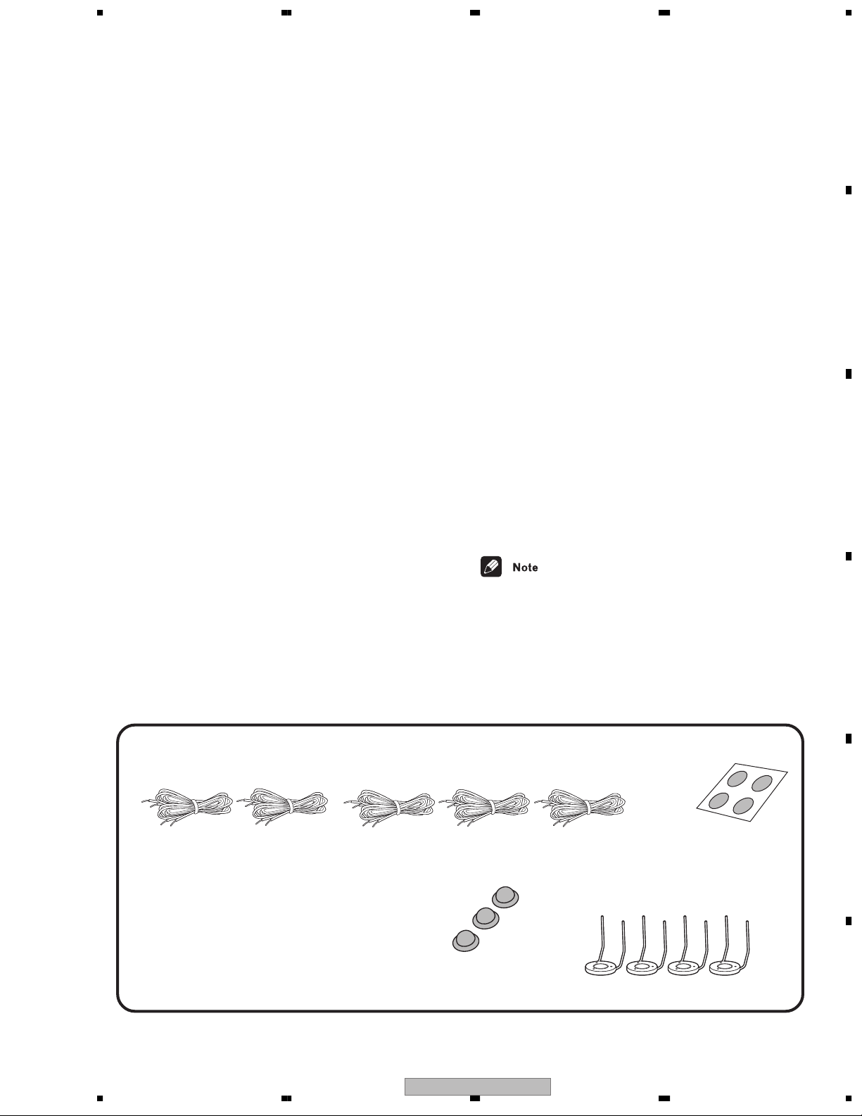
accessories
Speaker cords
10 m x 2 (for rear L-R speakers)
(SDS1118) (SDS1119)
Speaker cords
5 m x 3 (for center, front L-R speakers)
(SDS1115) (SDS1116) (SDS1117)
Non-skid pads
(center speaker) x3
(SEP1270)
D
Non-skid pads
(subwoofer) x4
(SEC1563)
E
Speaker Stands x 4
(SXG1067)
F
56
S-DV830
7
8
5
Page 6
1234
2. EXPLODED VIEWS AND PARTS LIST
NOTES:
A
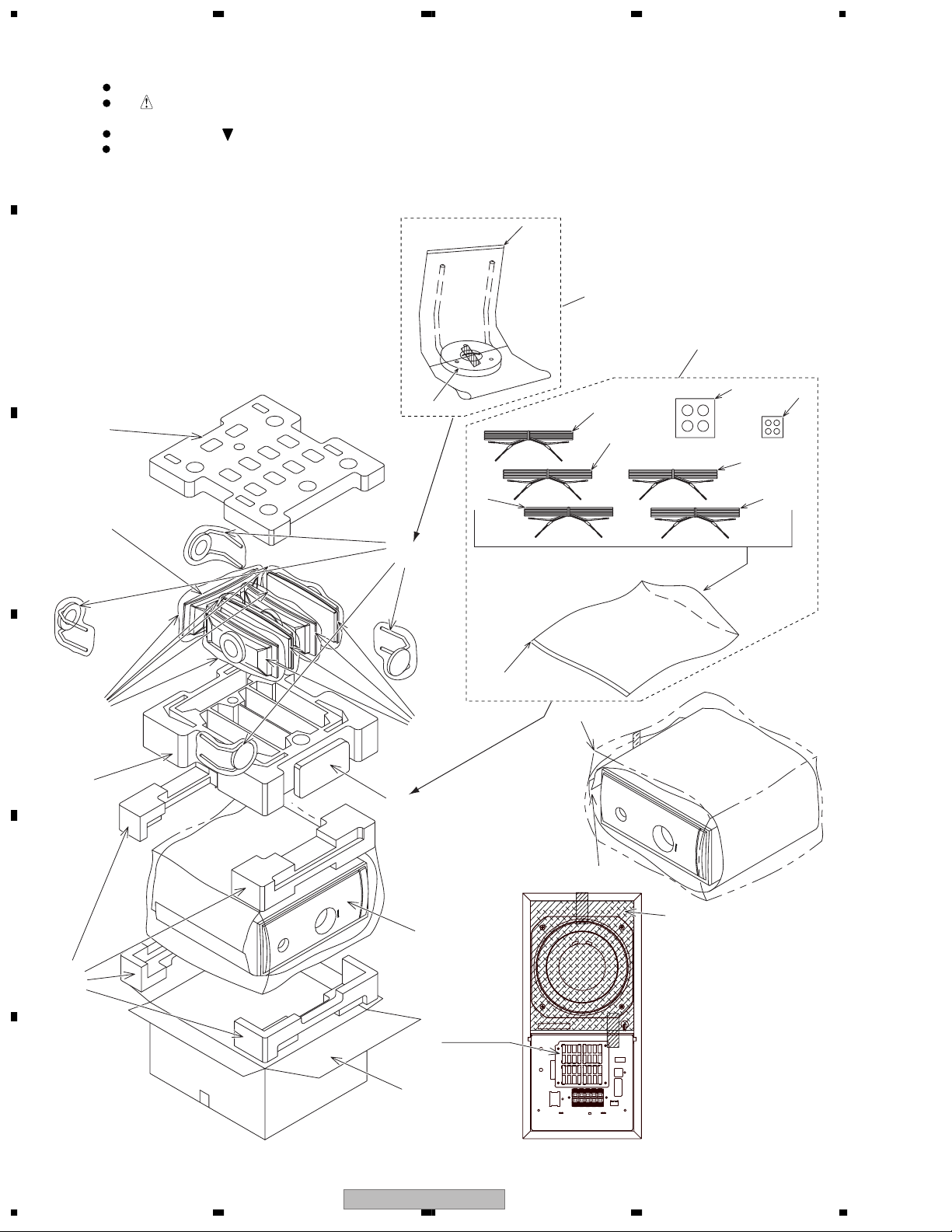
2.1 PACKING
B
16
C
1(2/2)
CENTER
SPEAKER
Parts marked by "NSP" are generally unavailable because they are not in our Master Spare Parts List.
The mark found on some component parts indicates the importance of the safety factor of the part.
Therefore, when replacing, be sure to use parts of identical designation.
Screws adjacent to mark on product are used for disassembly.
For the applying amount of lubricants or glue, follow the instructions in this manual.
(In the case of no amount instructions, apply as you think it appropriate.)
13
12
14
8
12
6
7
3
9
4
10
5
11
15
(1/2)
15
(2/2)
21
1(1/2)
FRONT
SPEAKER
17
3
2
POWERED
SUBWOOFER
FAN COVER
20
D
E
F
22
19
18
6
1234
S-DV830
Page 7
5 678
PACKING parts List
Mark
Mark
No. Description Part No.
NSP 1 Speaker System See Contrast table(2)
NSP 2 POWERED SUBWOOFER See Contrast table(2)
NSP 3 Accessories Set SME3373
4 Speaker cord SDS1115
(FRONT R/5m : Red)
5 Speaker cord SDS1116
(FRONT L/5m : White)
6 Speaker cord SDS1117
(CENTER/5m : Green)
7 Speaker cord SDS1118
(SURROUND L/10m : Blue)
8 Speaker cord SDS1119
(SUROUND R/10m : Gray)
9 Non-skid pads (subwoofer) SEC1563
10 Non-skid pads (center speaker) SEP1270
No. Description Part No.
11 Poly Bag S3 SHL1293
NSP 12 Accessories Set SME3374
13 Poly Bag S1 SHL1359
14 Speaker Stand SXG1067
15 Protector SHA2379
16 Top Protector SHA2380
17 Bottom Protector SHA2381
18 Protector SHB1097
19 Protection Sheet SHC1790
20 Packing Case See Contrast table(2)
NSP 21 Poly Bag SHL1223
22 Poly Bag S6 SHL1292
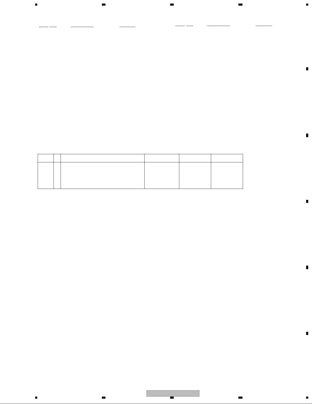
(2) CONTRAST TABLE
S-DV830/KUCXJI, S-DV99/MYXJI and S-DV99/NVXJI are constructed the same except for the following:
Mark No. Symbol and Description S-DV830/KUCXJI S-DV99/MYXJI S-DV99/NVXJI
NSP 1 Speaker System S-DV830ST/XJI/UCS-DV99ST/XJI/EWS-DV99ST/XJI/
NSP 2 POWERED SUBWOOFER S-DV830SW/
KUCXJI
20 Packing Case SHG2487 SHG2485 SHG2502
S-DV99SW/
MYXJI
EW
S-DV99SW/
NVXJI
A
B
C
D
E
F
56
S-DV830
7
8
7
Page 8
1234
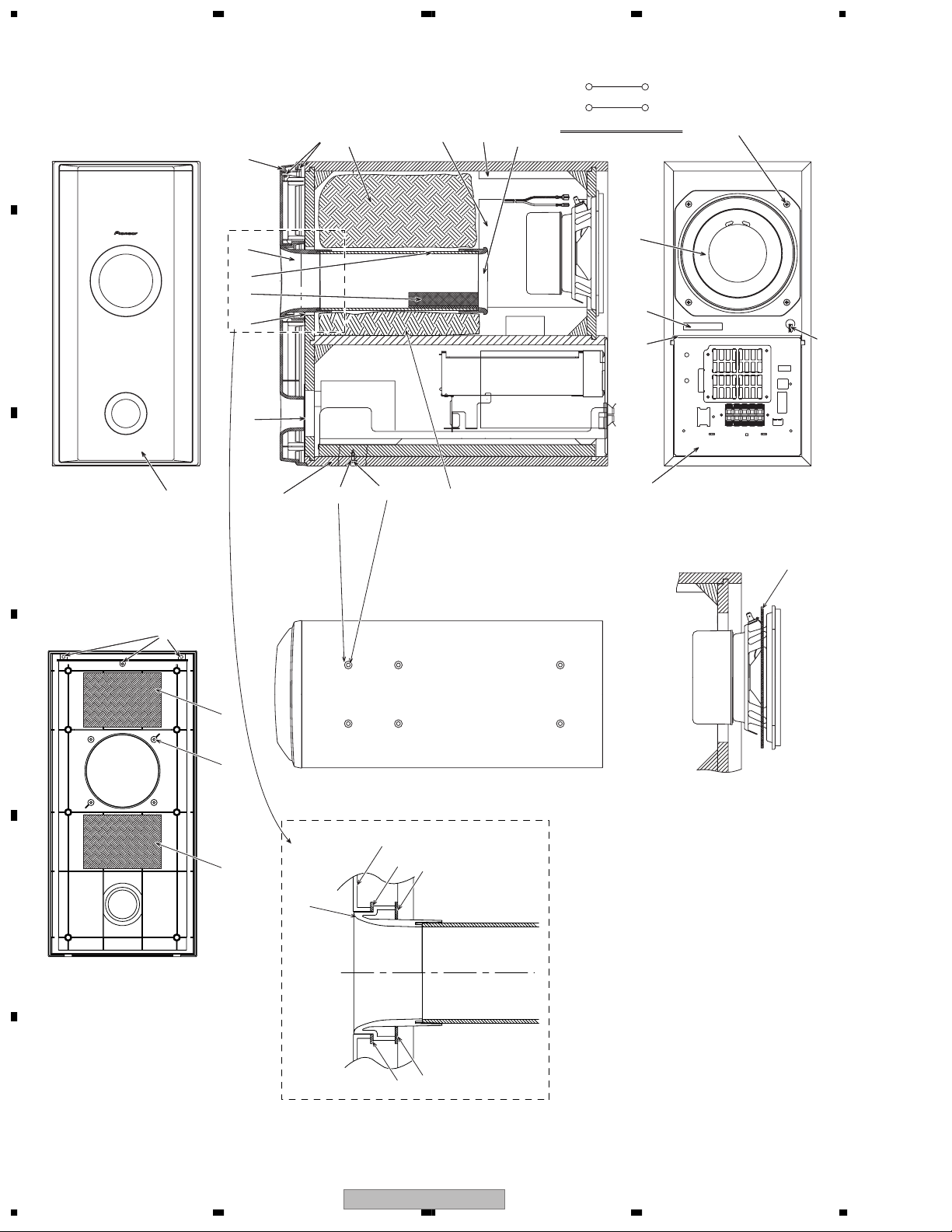
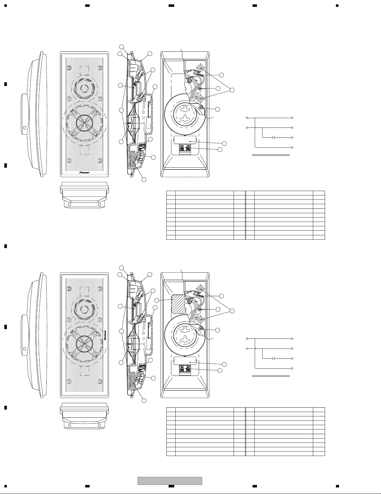
2.2 PRODUCT APPEARANCE SECTION [POWERD SUBWOOFER]
RED (-) RED (+)
A
20
13
15
9
10
6
B
16
C
14
5
1
22
21
11
26
BLACK (+) BLACK (-)
12
8
FOR SP
BLACK
IN WF
CIRCUIT DIAGRAM
RED
17
20
7
4
2
3
24
19
D
E
25
18
25
16
23
5
9
5
23
F
8
1234
S-DV830
Page 9

5 678
PRODUCT APPEARANCE SECTION parts List
Mark
No. Description Part No.
NSP 1 Cabinet SMM1994
NSP 2 Amp Ass'y See Contrast table(2)
3 Connecting Cord SDF1095
4Packing SEC1540
5Packing SEC1634
Mark
No. Description Part No.
NSP 16 Cosmetic Baffle SNK2672
17 Speaker T16EU92
18 Screw BPZ40P120FZB
19 Screw BPZ35P080FZB
20 Screw BYC40P160FZB
A
6 Damper SER1300
NSP 7 Stamped Serial Label See Contrast table(2)
NSP 8 Duct Ring SMR1339
NSP 9 Cosmetic Duct SMR1356
NSP 10 Paper Tube 70 SMR1362
NSP 11 Acoustic Absorbent SMV2077
NSP 12 Acoustic Absorbent SMV2078
NSP 13 Acoustic Absorbent SMV2079
NSP 14 Mesh SNC1188
NSP 15 Cosmetic Board SNK2673
21 Screw BYC40P200FZB
22 Washer WA43F090M080
NSP 23 Gasket SEC1735
NSP 24 Gasket SEC1736
25 Acoustic Absorbent SMT1216
26 Acoustic Absorbent SMT1217
(2) CONTRAST TABLE
S-DV830SW/KUCXJI, S-DV99SW/MYXJI and S-DV99SW/NVXJI are constructed the same except for the following:
Mark No. Symbol and Description
NSP 2 Amp Ass'y AXX7156 AXX7153 AXX7154
NSP 7 Stamped Serial Label SME3396 SME3380 SME3380
S-DV830SW/
KUCXJI
S-DV99SW/
MYXJI
S-DV99SW/
NVXJI
B
C
D
E
F
56
S-DV830
7
8
9
Page 10
1234
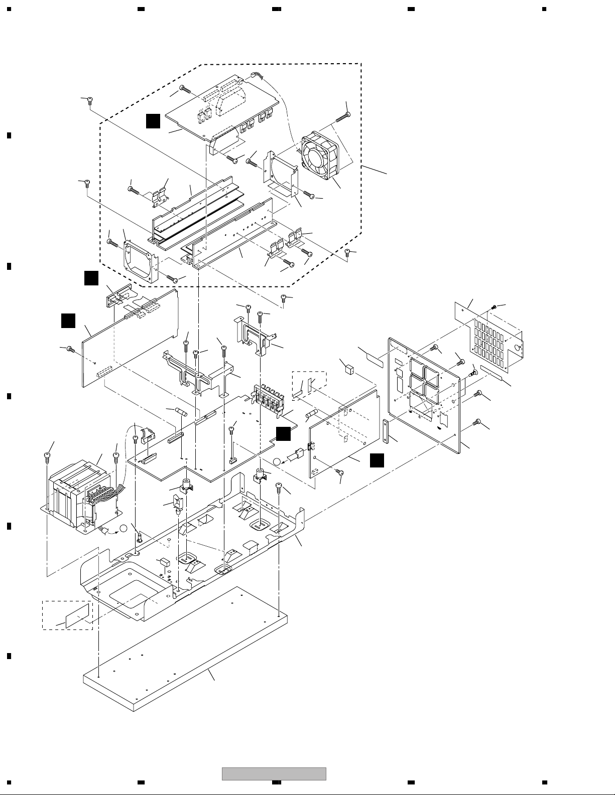
2.3 AMPLIFIER ASSY
A
24
34
35
C
29
34
34
15
19
31
33
30
34
32
31
33
34
24
25
25
24
7
31
10
24
34
34
24
25
11
S-DV830SW
37
3
6
Only
39
24
22
12
D
A
19
26
24
24
B
B
2
C
D
A
24
23
34
32
34
4
24
23
5
14
A
28
17
24
27
20
36
1
E
9
16
21
24
24
13
E
38
S-DV830SW
Only
18
F
10
1234
S-DV830
8
Page 11
>
>
>
>
>
>
>
>
5 678
AMPLIFIER ASSY parts List
Mark
No. Description Part No.
1 PRIMARY ASSY See Contrast table(2)
2 AF ASSY AWU8096
3POWER ASSY AWU8097
4 TRADE 1 ASSY AWU8028
5POWER TRANSFORMER T1 See Contrast table(2)
6 Fuse (FU1) See Contrast table(2)
7 Fuse (FU4) See Contrast table(2)
NSP 8 Chassis ANA7109
9 Rear Panel See Contrast table(2)
10 Hs Holder F ANG7439
11 Hs Holder R ANG7440
12 Cushion B AEB7290
13 Cushion AEB7319
14 Card Spacer AEC7133
15 Wire Saddel AEC7297
16 Nylon Rivet AEC7318
17 Fan Cover AEC7427
18 Wood Base AMM7008
NSP 19 PCB Mould AMR1525
20 Rocking Card Spacer ONK1035
Mark
No. Description Part No.
23 Screw SBA1061
24 Screw BBZ30P080FMC
25 Screw BBZ30P200FMC
26 Screw BYC40P140FMC
27 Screw PSC30P080FNI
NSP 28 AMP MODULE 6CH AXQ7242
29 6CH AMP ASSY AWM7720
30 DC Fan Motor AXM7025
31 FET Bracket ANG7418
32 Fan Plate ANG7462
33 Heat Sink ANH7166
34 Screw BBZ30P140FMC
35 Screw BBZ30P300FZK
NSP 36 USE ASSY • • • • •
NSP 37 Fuse Card See Contrast table(2)
38 65 Label See Contrast table(2)
NSP 39 Fuse Caution Label See Contrast table(2)
A
B
C
NSP 21 SP Label AAX7956
NSP 22 Serial Paper RRW-168
(2) CONTRAST TABLE
S-DV830SW/KUCXJI, S-DV99SW/MYXJI and S-DV99SW/NVXJI are constructed the same except for the following:
Mark No. Symbol and Description
1 PRIMARY ASSY AWU8003 AWU8001 AWU8001
5Power Transformer ATS7368 ATS7367 ATS7367
6 Fuse (FU1 : 6.3A) REK1069 Not used Not used
6 Fuse (FU1 : T3.15A) Not used REK1027 REK1027
7 Fuse (FU4 : 6.3A) REK1069 Not used Not used
7 Fuse (FU4 : T5A) Not used REK1029 REK1029
9 Rear Panel ANC8231 ANC8224 ANC8225
NSP 37 Fuse Card AAX2374 Not used Not used
38 65 Label ARW7050 Not used Not used
NSP 39 Fuse Caution Label VRW-548 Not used Not used
S-DV830SW/
KUCXJI
S-DV99SW/
MYXJI
S-DV99SW/
NVXJI
D
E
56
S-DV830
F
7
8
11
Page 12
1234
2.4 PRODUCT APPEARANCE SECTION [SPEAKER SYSTEM]
• CS ASSY (Front/Surround)
A
1
2
3
8
10
4
7
B
9
C
11
8
6
1
Punching Net Assy
2
Baffle
3
Cabinet
4
Gasketg
5
Input Terminal Board
6
Acoustic Absorbent
7
Packing
8
Network Assy
9
Speaker(Mid)
10
Speaker(Tw)
8
11
13
12
(+)
IN
(-)
14
5
Num. No.No. PARTSPARTS Num.
1
1
1
2
1
1
1
1
1
1
CIRCUIT DIAGRAM
11
Screw(M3.5 x 8)
12
Screw(M4 x 8)
13
Screw(M4 x 14)
14
Label Back
BLUE(+)
Mid Range
BLACK(-)
RED(+)
Tw
WHITE(-)
3
4
6
1
• CS ASSY (Center)
D
E
F
1
2
10
4
9
3
8
15
7
11
8
6
1
Punching Net Assy
2
Baffle
3
Cabinet
4
Gasketg
5
Input Terminal Board
6
Acoustic Absorbent
7
Packing
8
Network Assy
9
Speaker(Mid)
10
Speaker(Tw)
8
11
13
12
(+)
IN
(-)
14
5
Num. No.No. PARTSPARTS Num.
1
1
1
2
1
1
1
1
1
1
CIRCUIT DIAGRAM
11
Screw(M3.5 x 8)
12
Screw(M4 x 8)
13
Screw(M4 x 14)
14
Label Back
15
Rubber Magnet
BLUE(+)
Mid Range
BLACK(-)
RED(+)
Tw
WHITE(-)
3
4
6
1
1
12
1234
S-DV830
Page 13

5 678
PRODUCT APPEARANCE SECTION parts List
Mark
No. Description Part No.
NSP CS ASSY (FS) SMW1769
NSP CS ASSY (C) SMW1770
For S-DV830ST
NSP Stamped Model Label SME3391
NSP ....Label Back SAN3243
NSP Stamped Model Label SME3392
NSP ....Label Back SAN3244
NSP Stamped Model Label SME3393
NSP ....Label Back SAN3245
NSP Stamped Model Label SME3394
NSP ....Label Back SAN3246
NSP Stamped Model Label SME3395
NSP ....Label Back SAN3247
For S-DV99ST
NSP Stamped Model Label SME3375
NSP ....Label Back SAN3232
NSP Stamped Model Label SME3376
NSP ....Label Back SAN3233
NSP Stamped Model Label SME3376
NSP ....Label Back SAN3234
NSP Stamped Model Label SME3377
NSP ....Label Back SAN3235
NSP Stamped Model Label SME3379
NSP ....Label Back SAN3236
No. Description Part No.
Mark
CS ASSY (FS)
Punching Net Assy SET1046
NSP ....Gasket (268 x 18.5 ,t=1) SEC1705
NSP ....Gasket ( 100 x 10 ,t=1) SEC1706
NSP ....Punching Net SNC1196
NSP Baffle SNK2674
NSP Cabinet SNK2676
NSP Gasket (20 x 20 ,t=1) SEC1711
Gasket (110 x 7 ,t=1) SEC1732
Gasket (80 x 7 ,t=1) SEC1733
NSP Gasket (10 x 10 ,t=1) SEC1734
Packing (34.5 x 48.5 ,t=1) SEE1084
NSP Felt SER1331
Input Terminal Board SKX1086
Acoustic Absorbent SMT1215
(50 x 30 ,t=15)
NSP Acoustic Absorbent SMV2171
(90 x 10 ,t=10)
Network Assy SWN1712
Speaker (MID) D87ER25-51D
Speaker (TW) FA52AP39-52D
Screw (for Input Terminal,TW) BPZ35P080FZB
Screw (for MID) BPZ40P080FZB
Screw (for BF-CB) BPZ40P140FZB
A
B
C
CS ASSY (C)
Punching Net Assy SET1047
NSP ....Gasket (268 x 18.5 ,t=1) SEC1705
NSP ....Gasket (100 x 10 ,t=1) SEC1706
NSP ....Punching Net SNC1199
NSP Baffle SNK2674
D
NSP Cabinet SNK2676
NSP Gasket (20 x 20 ,t=1) SEC1711
Gasket (110 x 7 ,t=1) SEC1732
Gasket (80 x 7 ,t=1) SEC1733
NSP Gasket (10 x 10 ,t=1) SEC1734
Packing (34.5 x 48.5 ,t=1) SEE1084
NSP Felt SER1331
Input Terminal Board SKX1086
Acoustic Absorbent SMT1215
(50 x 30 ,t=15)
NSP Acoustic Absorbent SMV2171
(90 x 10 ,t=10)
NSP Rubber Magnet SYM1083
Network Assy SWN1712
Speaker (MID) D87ER25-51D
Speaker (TW) FA52AP39-52D
Screw (for Input Terminal,TW) BPZ35P080FZB
Screw (for MID) BPZ40P080FZB
Screw (for BF-CB) BPZ40P140FZB
S-DV830
56
E
F
7
8
13
Page 14

1234
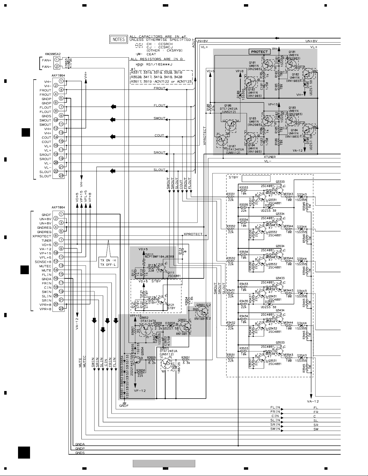
3. BLOCK DIAGRAM AND SCHEMATIC DIAGRAM
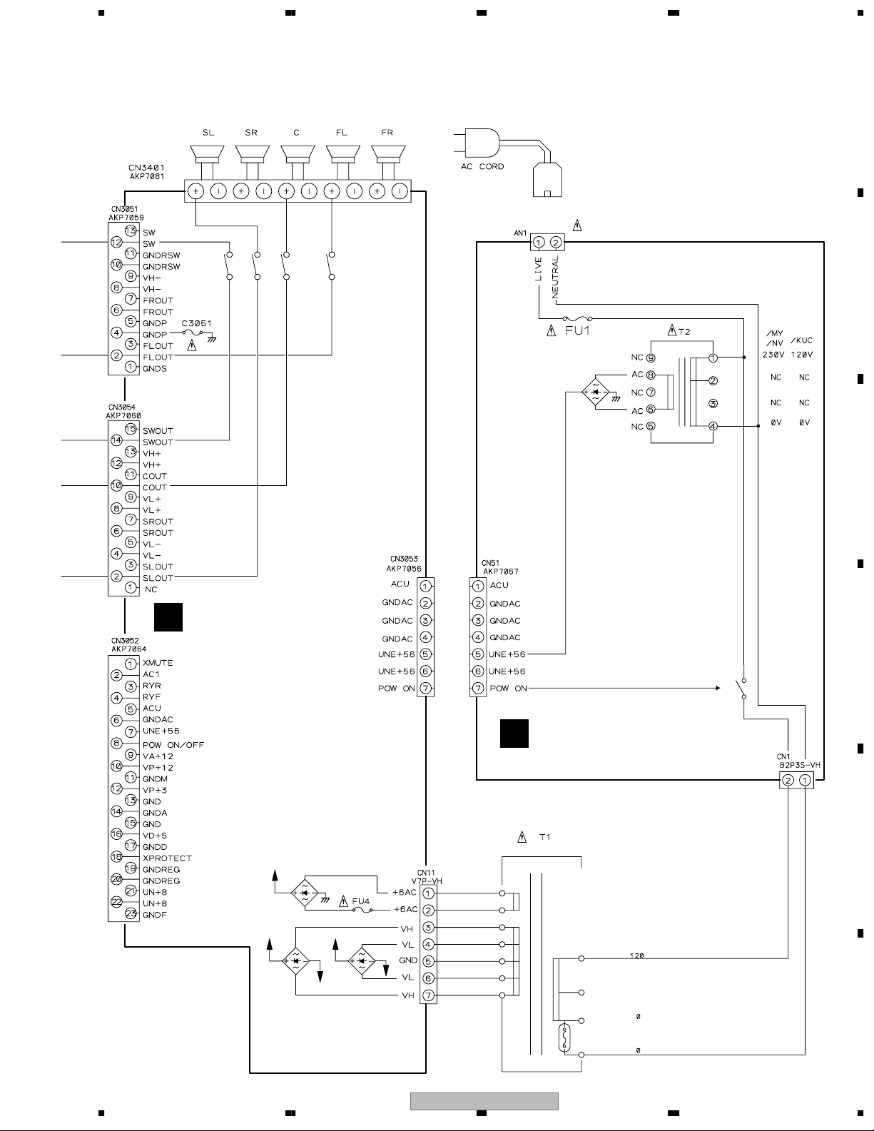
3.1 BLOCK DIAGRAM AND OVERALL CONNECTION DIAGRAM
A
6CH AMP ASSY
C
B
(AWM7720)
IC3301 STK402-270
16 1618
TRADE 1
B
ASSY
(AWU8028)
C
D
E
IC3401 STK402-270
16 1618
IC3101(1/2)
UPC4570
7
1
IC3103(1/2)
BA4558F
1
IC3104(2/2)
BA4558F
7
IC3102(1/2)
BA4558F
5
6
3
2
3
2
5
6
SLP
SLN
SWP
SWN
7
IC3104(1/2)
BA4558F
FLP
3
2
FLN
CP
3
CN
2
IC3004(1/2)
BA4558F
3
2
5
6
5
6
IC3002(1/2)
BA4558F
1
1
1
IC3003(1/2)
BA4558F
7
IC3004(2/2)
BA4558F
5
7
6
IC3103(2/2)
BA4558F
IC3001 M62446AFP
17
15
11
9
6
31
33
34
36
AF ASSY
A
(AWU8096)
F
14
1234
S-DV830
Page 15
5 678
A
Note : When ordering service parts,
be sure to refer to
"EXPLODED VIEWS and
PARTS LIST" or "PCB
PARTS LIST".
B
POWER ASSY
D
(AWU8097)
RY3461(1/3)
RY3561(2/3)
RY3361(1/3)
D51
PRIMARY ASSY
E
(S-DV830SW: AWU8003)
(S-DV99SW: AWU8001)
C
D
RY51(2/2)
UN+8
D41
VH+ VL+
VH-
D31
VL-
D11
S-DV830
56
E
F
7
8
15
Page 16

1234
3.2 AF and TRADE 1 ASSY
A
(SW)
(FL)
(FL)
(SW)
(C)
(SL)
B
(C)
(SL)
(FL)
(FL)
(FL)
(FL)
(FL)
(SL)
(SL)
(SL)
(SL)
(FL)
(FL)
C
(FL)
(SL)
(SW)
(C)
(FL)
(C)
(SL)
(SW)
D
CN3052
D
(C)
(C)
(C)
(SW)
E
(SW)
(SW)
(SW)
F
(C)
: C ch AUDIO SIGNAL ROUTE
(SW)
: SW ch AUDIO SIGNAL ROUTE
16
A
(FL)
: FL ch AUDIO SIGNAL ROUTE
(SL)
: SL ch AUDIO SIGNAL ROUTE
S-DV830
1234
Page 17

5 678
(FL)
(SL)
(C)
(SL)
(C)
(FL)
(SL)
(SW)
(C)
(SL)
(FL)(FL)
(FL)
(SW)
AF ASSY (AWU8096)
A
(FL)
(C)
(SL)
A
B
CN3002
C
C
(SW)
(SW)
(SW)
(SW)
(SW) (SW)
CN3051
D
CN3054
D
: The power supply is shown with the marked box.
56
S-DV830
(SW)
(FL)
(SW) (SW)
(C) (C)
(SL) (SL)
TRADE 1 ASSY
B
(AWU8028)
7
(SW)
(FL)
D
To Speaker
E
CN3001
C
F
BA
17
8
Page 18
1234
3.3 6CH AMP ASSY
A
CN3651
to FAN
Motor
CN3001
(FL)
2
B
(SW)
CN3705
A
C
CN3002
(C)
(SL)
Non Distortion Circuit
5
CN3704
A
D
(C)
(SW)
E
F
(FL)
(SL)
3
C
18
1234
S-DV830
Page 19

5 678
A
6CH AMP ASSY (AWM7720)
C
B
(SL)
(C)
C
(FL)
D
(SW)
E
: Refer to
"7.1.1 PROTECTION CIRCUIT"
: The power supply is shown with the marked box.
S-DV830
56
(FL)
: FL ch AUDIO SIGNAL ROUTE
(SL)
: SL ch AUDIO SIGNAL ROUTE
(C)
: C ch AUDIO SIGNAL ROUTE
(SW)
: SW ch AUDIO SIGNAL ROUTE
7
C
8
F
19
Page 20

1234
3.4 POWER ASSY
A
B
C
24.784V
-25.513V
15.883V
38.43V
-39.21V
14.66V 12.112V
CAUTION : FOR CONTINUED PROTECTION AGAINST
RISK OF FIRE. REPLACE ONLY WITH
SAME TYPE NO. 491005 MFD, BY
LITTELFUSE INK. FOR IC3051.
(FL)(FL)(FL)
(FL)
(SL)
(C)
(C)
D
(SW)
E
(SL)
(SW)
(SW)
CN51
E
(SW)
(SW)
(C)
(SL)
F
20
D
CN3707
A
CN3703
B
S-DV830
1234
B
CN3706
Page 21

5 678
POWER ASSY
D
(AWU8097)
(FL)
(SL) (SL) (SL)
(FL)
: The power supply is shown with the marked box.
(FL)
: FL ch AUDIO SIGNAL ROUTE
(SL)
: SL ch AUDIO SIGNAL ROUTE
(C)
: C ch AUDIO SIGNAL ROUTE
(SW)
: SW ch AUDIO SIGNAL ROUTE
A
(FL)
B
(FL)
To Speaker
(C)(C)
C
(SW) (SW)
(SW)
1
4
(C)(C) (C)
(SW)
(SW)
: Refer to
"7.1.1 PROTECTION CIRCUIT"
D
E
• NOTE FOR FUSE REPLACEMENT
CAUTION -
FOR CONTINUED PROTECTION AGAINST RISK OF FIRE.
REPLACE WITH SAME TYPE AND RATINGS ONLY.
56
S-DV830
F
D
7
8
21
Page 22

1234
3.5 PRIMARY ASSY
A
• NOTE FOR FUSE REPLACEMENT
B
CAUTION -
FOR CONTINUED PROTECTION AGAINST RISK OF FIRE.
REPLACE WITH SAME TYPE AND RATINGS ONLY.
CN11
D
C
D
11.619V
E
CN3053
D
F
E
22
1234
S-DV830
Page 23

5 678
PRIMARY ASSY
E
(S-DV830SW: AWU8003)
(S-DV99SW: AWU8001)
A
B
C
D
E
56
S-DV830
F
E
7
8
23
Page 24

1234
1XMUTE
D
C3032
8
8
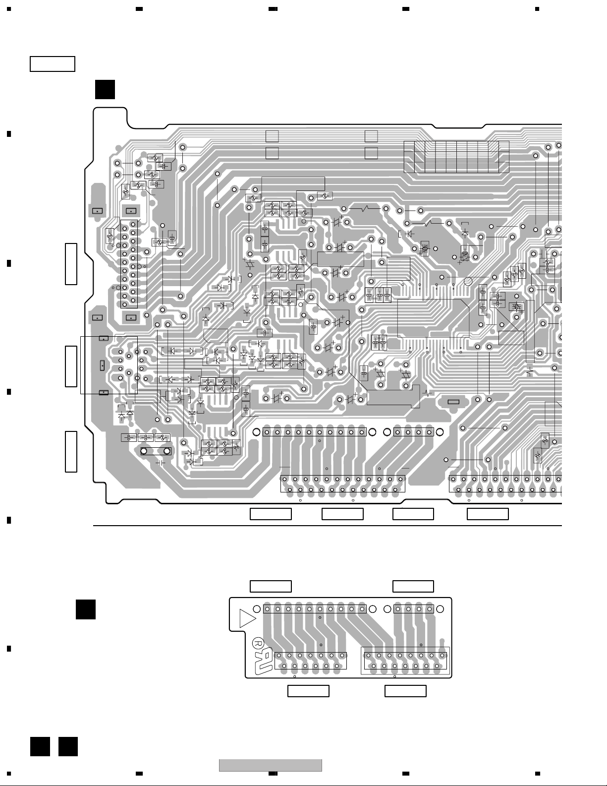
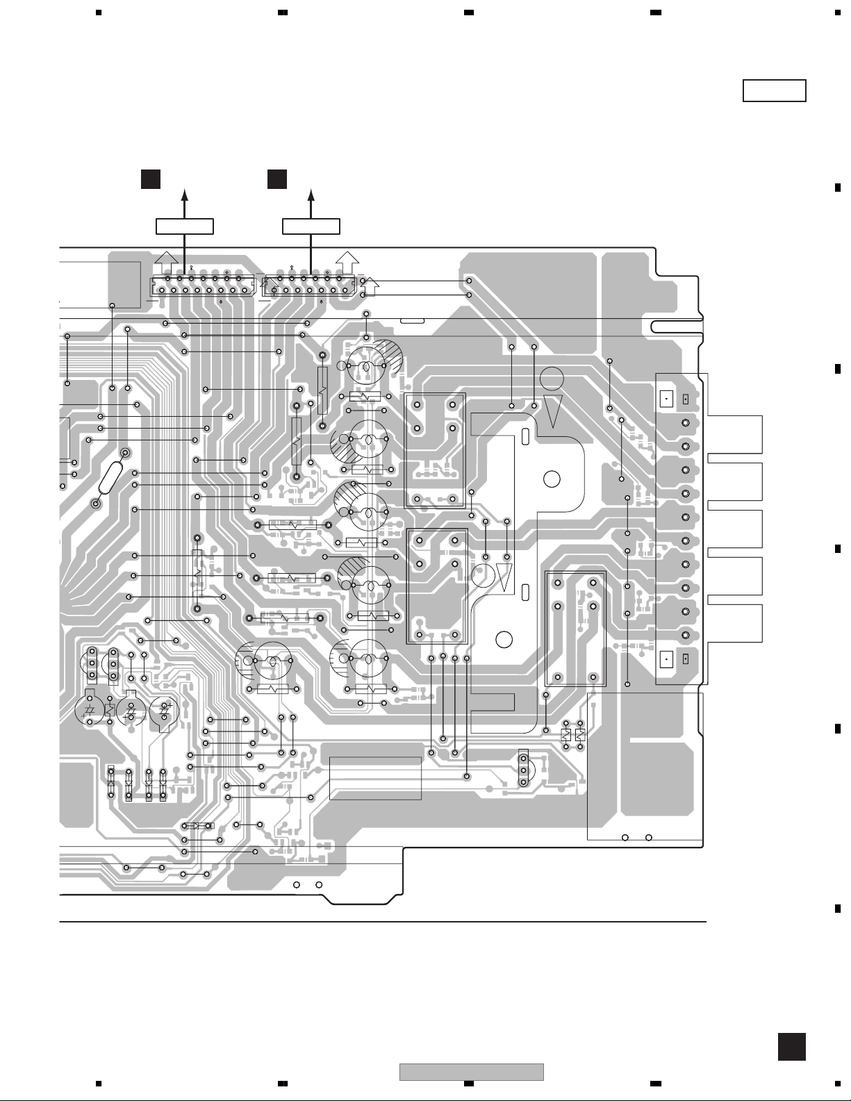
4. PCB CONNECTION DIAGRAM
4.1 AF and TRADE 1 ASSY
A
SIDE A
A
AF ASSY
D
CN3703
CN3052
GNDA
J3705
W189
XMUTE
GNDA
W167
C3037
D3006
D3004
D3005
R3040
B
C3038
R3041
GNDD
W313
F
D3003
W135
C
C3081
C3082
VA-12
W116
W338
VA+12
VP+12
W337
VP+8
D
W117
1
RYF
23
W191
GNDAC
W190
W169
R3071
VD+5
VP+8
VA+12
W140
W139
W118
W334
NE M PF2
23
W194
UNE+56
P ON/OFF
W192
W195
W193
VP+12
W170
GNDA
W138
W137
W136
W141
W339
W375
W335
FL ANDREW OUT
FR ANDREW OUT
W168
W142
VA+12
W196
W356
VP+12
W171
CN3703
VP+3
VD+5
GNDM
W198
W197
W172
C3127
W357
W143
C3126
C3006
W359
C3005
W358
DC FC
1
1
W351
C3125
C3124
FL
EVOL OUT
23
GNDF
C3121
FR
C ANDREW OUT
W119
XPROTECT
W199
W200
W174
C3108
W173
C3107
W317
C3122
EVOL OUT
SW ANDREW OUT
SR ANDREW OUT
SL ANDREW OUT
W122
W341
W340
W175
GNDA
W125
W176
VP+8
C3129
SRIN
VP+8
C3119
W342
C3011
SWIN
20.SLIN
W201
C3128
W144
W345
C3012
FRIN
CIN
GNDA
15.FLIN
23
W202
SL
EVOL OUT
VFL+5
SENSE+8
MUTEC
MUTE
1
1
CN3704
W203
W204
C3017
EVOL OUT
SW
C3118
GNDA
W343
TUNER
VD+5
VA-12
10.VP+15
W205
W145
SR
W129
XPROTECT
5.GNDREG
GNDA
C
W146
UN+8
UN+8
GNDREG
J3705
GNDA
EVOL OUT
EVOL OUT
1.GNDF
7
0
NOTE FOR PCB DIAGRAMS :
1. Part numbers in PCB diagrams match those in the schematic
diagrams.
2. A comparison between the main parts of PCB and schematic
diagrams is shown below.
Symbol In PCB
E
Diagrams
BCE
BCE
D
Symbol In Schematic
Diagrams
BCEBCE
BCE
DGGSS
BCE
DGS
F
A
24
1234
Part Name
Transistor
Transistor
with resistor
Field effect
transistor
Resistor array
3-terminal
regulator
3. The parts mounted on this PCB include all necessary parts for
several destinations.
For further information for respective destinations, be sure to
check with the schematic diagram.
4. View point of PCB diagrams.
Connector
Capacitor
SIDE A
SIDE B
S-DV830
P.C.Board
Chip Part
C
Page 25

S
VA
12
GNDA
E
3
W343
C
-
W204
C3017
TUNER
VD+5
GNDA
W205
W145
W146
SR
W129
UN+8
GNDREG
XPROTECT
5.GNDREG
C
UN+8
1.GNDF
J3705
GNDA
EVOL OUT
C3032
EVOL OUT
5 678
A
SIDE A
W209
10.SRP
COUT
VH+
SLNCNSLP
VH+
SWOUT
W207
GNDA
W157
GNDD
W346
GNDS
FLOUT
10.SWOUT
W160
FLOUT
GNDP
GNDD
W161
GNDA
W162
FROUT
5.GNDP
GNDM
W378
FROUT
VH-
20
CN3702
CN3601
1.VH-
W208
B
20
CN3702CN3701CN3601
1
1
CN3701
C
To DVD/CD TUNER To DVD/CD TUNERTo Speaker
1
D
AC1
RYR
1.XMUTE
W177
W180
W148
GNDD
W130
GNDD
RYF
GNDA
VD+5
W147
POW ON/OFF
UNE+56
5.GNDAC
W344
W336
VA+12
C3022
W150
23
GNDM
VP+3
10.VP+12
VD+5
23
1
1
GND
GNDA
15.GND
R3036
VD+5
23
GNDD
VA+12
C3021
1
XPROTECT
UN+8
GNDREG
GNDREG
20.GNDREG
W178
C3019
41 101
J3701
1
UN+8
W182
GNDF
W151
EVOL IN
FR
W153
EVOL IN
C3020
EVOL IN
SW
1
VP+8
1.GNDA
R3035
FL
SR
VP+8
VP+12
5.GNDM
EVOL IN
SL
EVOL IN
VP+3
GND
CN3705
UNE+56
10.VA-12
C3043
C3003
C3045
C3004
C3010
C3016
NC
C3048
C3009
DATA
CLK
W183
W154
W155
J3702
NC
15.LATCH
23
XMUTE
ACPULSE
NC
EVOL IN
C
23
1
XPROTECT
20.POW ON/OFF
W184
W156
FLN
1.SWN
C3015
10
SLOUT
VL-
SLOUT
FLP
SROUT
20.VL-
VP+8
W206
FRP
5.SWP
W131
SROUT
C3047
FRNCPSRN
VL+
VL+
VP+8
W361
15.COUT
CN3704 CN3705
CN3002
C
1
41 101
J3703
CN3706 CN3707
1
1
CN3054
D
56
CN3001
C
1
J3704
TRADE ASSY
15
15
14
J3702J3701
J3704J3703
10
NE M PF2
TRADE 1 ASSY
B
(ANP7432-D)
E
AWU8028
1
CN3707CN3706
CN3051
D
13
131
F
BA
S-DV830
7
8
25
Page 26
A
SENSE+8
3
3
SIDE B
1234
AF ASSY
A
C3041
R3096
POWON/OFF
20
ACPULSE
GNDM
GNDM
12
10
9
8
7
11
D3023
D3025
D3011
C3566
CLK
VA-12
UNE+56
VP+3
VP+12
VP+8
R3097
R3094
D3021
D3027
R3566
C3040
C3039
R3098
D3007
D3019
R3023
R3021
D3029
D3030
D3028
D3009
D3010
D3026
D3024
D3008
D3015
D3017
R3025
R3027
41
R3022
R3024
IC3004
R3028
R3026
R3047
XPROTECT
XMUTE
LATCH
CN3702
GNDM
VP+8
GNDA
R3095
GNDM
DATA
GND
GND
1
1
B
CN3702CN3701CN3601
C
4
CN3701
3
6
2
5
1
D3013
C3568
D
CN3601
C3570
AWU8098
AWU8096
R3089
R3003 R3005
R3001
R3007
IC3002
41
C3001C3002
D3012
D3014
IC3003
41
C3007
D3022
D3018
D3016
D3020
R3018
R3012
R3014 R3016
C3014
R3029
C3013
VH-
SW
85
R3030
GNDRSW
23
1
R3009
R3010
85
R3002
R3004
C3008
85
R3020
GNDS
FROUT
FLOUT
5
AWU8053
AWU8005
AF ASSY
R3090
R3008
R3006
C3030
GNDP
VH+
SWOUT
15
10
D3001
C3029
C3028
R3013 R3015
R3011
COUT
20
666
777
888
999
C3023
C3025
C3026
C3027
211
21
22
IC3001
R3019
R3017
VL-
1
SROUT
SLOUT
1410 1
VL+
555
R3050
23
123
444
D3002
333
42 22
5
8
222
C3033
1
C3036
42
7
111
C3024
GNDF
1-A
AWU
000
R3042
R3043
R3044
R3155
C3116
C3031
R3121
C3117 R3126
C3035
C3034
R3049
R3160
VD+5
GNDREG
UN+8
UN+8
GNDREG
XPROTECT
TUNER
15
10
R3159
VA-12
C3115
R3122
R3112
C
R
VP+15
20
VFL+5
E
F
A B
26
J3702 J3701
IC3001
CN3704CN3705
J3704 J3703
J3704J3703
SROUT
CN3706
1410 1
SLOUT
VL-
TRADE 1 ASSY
B
NE M PF2
SW
GNDRSW
13 1
VH-
FROUT
GNDP
FLOUT
CN3707
COUT
15 1
GNDS
VH+
SWOUT
VL+
CN3707 CN3706
1234
S-DV830
Page 27
UN
8
5 678
SIDE B
A
CN3703
20
23
AWU
R3087
VP+12
VA+12
POWON/OFF
R3131
R3129
41
R3137
UNE+56
GNDAC
IC3104
1
ACU
RYF
RYR
AC1
R3139
R3142
C3103
XMUTE
R3143
R3101
R3141
R3138
R3106
R3102
C3101
R3110
C3131
R3104
C3104
C3102
R3103
R3105
R3109
GNDREG
GNDF
UN+8
UN+8
GNDREG
0001-A
C3115
R3042
R3043
R3044
C3035
C3034
+
GNDREG
XPROTECT
GNDREG
10
C3031
R3121
C3117
R3126
VD+5
TUNER
15
R3155
C3116
R3049
R3159
R3160
R3122
R3112
VA-12
VP+15
C3110
R3114
20
SENSE+8
VFL+5
R3146
R3123
R3124
Q3103
R3144
41
85
IC3103
C3112
R3116
C3111
R3120
R3118
MUTEC
MUTE
FLIN
GNDA
FRIN
CIN
SWIN
1
23
R3119
R3111
SLIN
SRIN
R3145
R3127
C3120
VP+8
VP+8
R3086
R3152
41
IC3102
C3109
R3113
R3115
XPROT
GNDD
VD+5
C3106
R3147
C3134
C3105
C3123
R3130
R3133
C3113C3114
85
R3132
R3117
R3151
C3133
GND
GNDA
GND
VP+3
GNDM
R3125
C3130 R3148
R3128
85
R3135
R3134
R3136
10
C3132
R3150
R3108
R3158
R3154
C3050
Q3102
R3140
Q3101
IC3101
41
85
R3107
R3153
Q3002
C3049
R3157
R3149
515
Q3003
23
Q3001
1
R3045
R3037
R3032
R3031
Q3007
Q3006
Q3005Q3004
R3038
R3046
Q3008
Q3081
R3081
C3018
R3033
R3082
NE M PF2
R3039
R3085
Q3009
R3034
R3083
B
R3084
C
R3048
D
4
(ANP7432-D)
IC3101IC3104 Q3006Q3001Q3003Q3002 Q3007 Q3008 Q3009Q3081Q3005Q3004Q3101IC3102IC3103
E
F
A
56
S-DV830
7
8
27
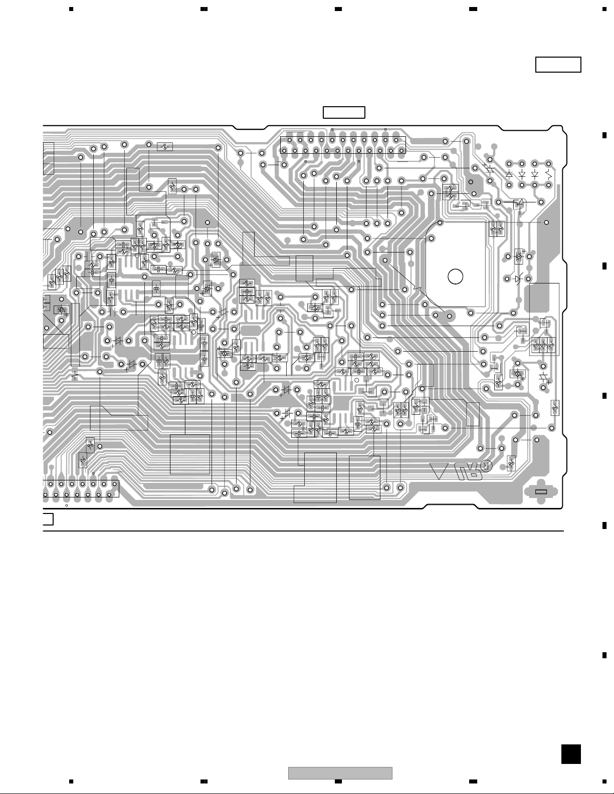
Page 28

1234
4.2 6CH AMP ASSY
SIDE A SIDE A
A
B
C
D
CN3704
A
E
CN3705
A
F
C
6CH AMP ASSY
C3178
C3168
W102
FR1S P
C3167
W103W101
C3179
Production Code
C3318
C3317
W104
W105
W106
W107
FC DC
C82
D3652
W110
23
UN+8
CN3002
CN3002
1
1
123
W112
W112
23
23
W111
W111
FLOUT
FLOUT
CN3001
CN3001
CN3001
1
1
123
123
IC3301
IC3303
C91
C98
D3653
W108
C3653
W109
VA-12
IC3303
W113
SWOUT
W130
VL-
W114
VH+
1
Q91
IC81
C3401
C3302
Word Surface
D98
W122
D82
W123
D3654
W125
W126
IC3301
W129
word surface
W131
SROUT
W133
W135
VL+
C3501
W115
C3402
W116 W118
W117
C3502
W119
C3301
W120
IRFI9Z34G
Q91
W121
IC81
D3651
NJM7805FA
W124
1
1910
W157
Q62
Q61
Q3383
Q3384
D3424
D3423
W190
W190
W197
W197
VL+
VL+
D3392
D3392
W200
W200
W201
W201
C3507
C3408
C3407
W175
W175
-B
VL-
VL-
-B
-B
W189
+B
+B
IC3401
W187
W188
W191
W198
W198
IC3401
IC3401
1910
1
Q62
Q62
C72
C72
IRFI9Z34G
IRFI9Z34G
W199
W199
W202
W202
D3393
D3393
R3387
R3387
D3394
D3394
R3388
R3388
W203
W203
IC71
1910
1
D72
D72
Q61
W207
W207
IC71
IC71
Q3383
Q3383
Q3384
Q3384
W204
word surface
W205
C63
2SD2012
W206
W206
NJM7912FA
Surface
Word
Surface
D3389
D3389
D3390
D3390
IRFIZ34G
IRFIZ34G
Q3654
AWM
AMP Assy
W137
GNDP
R3428
-B
W141
GNDP
W170
W170
W142
W142
W150
W151
D3326
W154
W138
W139
W140
C3423
C3423
R3657
W136
GNDS
GNDS
SLOUT
SLOUT
C3651
Q3654
D3325
W158
7788
R3427
W143
W143
W144
W144
W172
D3327
D3328
W152
7787
W171
W171
C3324
C3577
C3478
C3477
C3578
C3378
C3377
GNDP
+B
C3652
W148
W145
W147
W146
W127
W146
W127
W147
D3655
C3307
1
R3317
W128
R3319
R3321
W132
R3322
R3318
R3320
C3308
C3508
1910
R3518
R3520
VH-
D3321
W155
W156
D3323
D3324
D3322
D3322
W149
W153
FROUT
VH+
W159
7786
C3424
D3428
C3422
D3427
C3321
W184
W184
W160
7720
SWOUT
SWOUT
GNDREG
GNDREG
SROUT
SROUT
W173
W192
W193
W194
W195
W196
C3322
W185
W185
AWM
W161
R3519
R3517
W164
R3420
R3418
D3426
C3421
R3419
R3417
VA-12
VA-12
VD+5
VD+5
VPF+15
VPF+15
VP+15
VP+15
C3323
W174
R3327
W177
W178
W179
R3328
W181
W181
W165
W166
D3425
W168
W167
XPROTECT
XPROTECT
VF-12
VF-12
GNDP
GNDP
W176
W182
W182
GNDP
GNDP
W183
W183
VL-
VL-
D3387
D3387
D3385
D3385
D3386
D3386
D3388
D3388
W163
W180
W180
D3422
R3422
R3421
D3421
W169
VL+
+B
W162
C102
C101
GNDP
D3391
D3391
(ANP7461-A)
C C
28
1234
S-DV830
Page 29
5 678
SIDE B SIDE B
C
6CH AMP ASSY
R3511
C3509
C3410
R3412
R62
R61
R63
SDG
R3389
GDS
R3390
BCE
R3411
C3409
R66
D101
R102
Q63
Q101
Q3381
Q102
Q103
R3410
R3407
R3405
R3385
R3386
R3409
C62
R68
R64
Q3381
Q3382
Q104
R3531
R3505
R3406
Q63
Q103
NP
R101
VL+
VL-
-B
Q3382
C3505
C3503
C3404
C3406
R3424
IC3401
R3423
C3405
1
C3403
R67
R65
C61
Q101Q102
R109
C71
R103
D105
R3383
R3384
E2
B2
C1
R3451
R3509
R3507
R3408
R104
NP
+B
R3591
R3491
Q104
R105
R106
D102
Q3333
Q3334
Q3534
C2
B1
E1
D3581
R3432
R3492
D3482
D3481
D106
VF-12
R3326
GNDP
VL+
D3343
+B
GNDP
-B
D3344
GNDP
R3381
R3382
Q3432
AWM
R3537
Q3531
Q3432
R3438
D3441
R3437 R3433
Q3431
R3431
VA-12
VD+5
VPF+15
VP+15
D3658
XPROTECT
C3326
R3339
Q3333
R3343
R3344
Q3334
R3340
Q3534
D3544
VL-
Q3331
Q3651
7720
7786
R3543
R3539
R3533
R3434
R3435
R3654
R3316
R3335
Q3332
7787
D3543
R3440
R3444
R3443
R3439
R3416
SROUT
R3651
R3655
R3656
R3333
D3341
R3334
R3534
R3540
R3538
R3544
Q3533
Q3653
Q3532
Q3652
7788
AMP Assy
Q3533
R3426
GNDP
Q3434
D3444
-B
GNDP
+B
D3443
Q3433
GNDP
SWOUT
GNDREG
Q3653
Q3651
R3331
Q3331
R3337
R3338
Q3332
R3332
Q3532
D3582
GNDS
SLOUT
Q3652
D3381
D3382
VH+
C3426
R3658
R3305
Q121
Q111
R3573
R3478
R3473
R3578
R3374
R3377
D3657
R3391
R3392
R3308
R3508
R3510
R3592
Q3371
R3577
R3474
R3477
R3574
R3378
R3373
R3532
FROUT
Q3572
Q107
R3545
R3446
R3445
R3546
R3346
R3345
D91
R91
D104
R122
R121
R123
Q121
Q111
R112
R111
R113
R3309
R3306
R3506
FAN SIDE
Q3471
Q3372
Q3472
Q3572
Q3371
R45
Q107
R3307
C3305
R3310
Q3571
Q3471
Q3372
TH121
R3323
C3303
R3324
C3306
C3304
C3504
C3506
Q106
R47
IC3301
D42
R114
R3575
Q106
R3512
Q92
Q43
R3476
R3475
R3576
R3376
R3375
G
Q92
Q43
TH111
C81R46
C3510
R93
S
R3501
R3402
R3401
R3502
R3302
R3301
R92
1
VH-
Q3502
Q3301
R3571 R3513
R3472
R3471
R3572
R3372
R3371
C97
R108
R3311
C3309
SROUT
R3351
R3312
C3310
VL+
Q3402
R3414
R3413
R3514
R3314
R3313
C92
R48
D
R97
R96
VA-12
SWOUT
VL-
VH+
Q3401
Q3302
Q3501
Q3402
Q3401
Q3502
R3504
Q3302
Q3301
R95
R94
UN+8
FLOUT
Q3504
R3503
R3404
R3403
Q3504
R3500
R3304
R3303
23 1
VPR+8
VPR+8
SRIN
SLIN
SWIN
CIN
FRIN
GNDA
FLIN
MUTE
MUTEC
SEN+8
VFL+5
VP+15
VA-12
VD+5
TUNER
XPRCT
GNDR
GNDR
UN+8
UN+8
GNDF
23 1
SLOUT
SLOUT
VL-
VL-
SROUT
SROUT
VL+
VL+
COUT
COUT
VH+
VH+
SWOUT
SWOUT
GNDS
FLOUT
FLOUT
GNDP
GNDP
FROUT
FROUT
VH-
VH-
FR1S P
CN3002
CN3001
A
B
C
D
E
F
(ANP7461-A)
C C
56
S-DV830
7
8
29
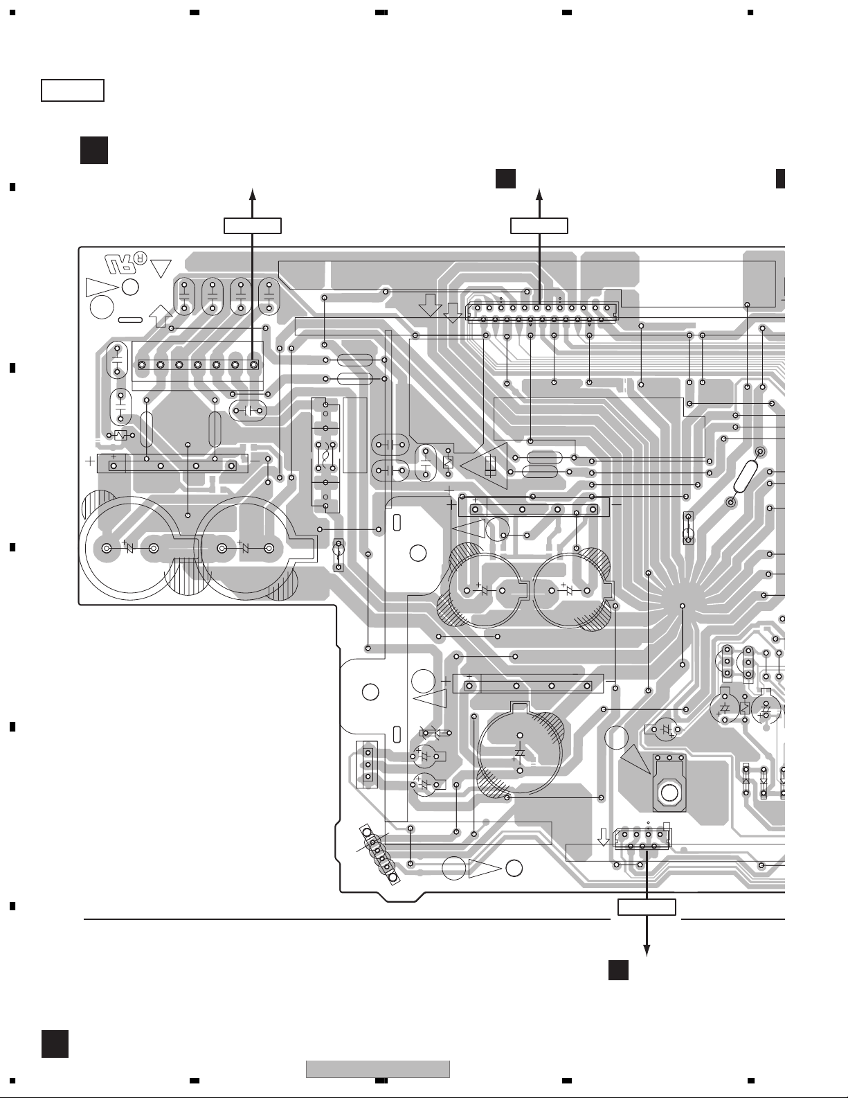
Page 30
1234
0
9
W
B
6
4.3 POWER ASSY
SIDE A
A
POWER ASSY
D
To Power Transformer
CN3703
A
CN3052CN11
NE M PF2
C13
IC32
W300
CN11
W280
4321
BOND
C14
D31
C12
+6AC +6AC GNDVL VLVH VH
VL+
VL-
1
C41
W281
W260
W364
W259
4700 u / 35
C34
H41
W365H42
W301
IC12
W322
IC41
IC11
W324
FU4
W320
BOND
W261
VR+12
OPEN SIDE
C15
CAUTION
RISK OF FIRE
C17
C16
R11
IC3051 N'UTILISER QUE LA
W303
123
1
W302
W304
W283
GNDA
VP+12
W282
GNDAC
W305
23
GNDREG
CN3052
GNDF
W284
UN+8
W286
VH-
W287
BY LITTELFUSE INC.
#491005 FOR IC3051 MFD.
W285
REPLACE WITH SAME TYPE
VH+
VH-
BOND
W267
W266
W265
W264
W250
CAUTION
IC3051
IC3052
W366
AS MARKED.
-REPLACE FUSE
VH+
W262
D11
A
BOND
W380
W263
W379
IC3054
IC3053
W360
VL+
VL-
4321
VH-
B
C11
I
OPEN SIDE
W321
C33
IC31
W246
431
W323
C31
7
C32
R31
C
BOND
REFERENCE 491005 DE CHEZ LITTELFUSE INC.
EN CAS REMPLACEMENT DES FUSIBLES
1
ATTENTION
GNDP
GNDS
W292
W291
VH+
VL+
VL-
W248
BOND
D
B
D32
W232
W216
C35
C37
W224
BOND
H
IC33
WORD SURFACE
E
IC41 IC33 Q3606 Q3
1
1
4
4
CN42
W233
W362
C18
BOND
4321
BOND
C42
6800u/25
W249
C19
W354
2200 u / 50
D41
C
CN3053
1
1
W376
W363
W234
C3603
1
7
7
OPEN SIDE
CN3053
CN51
E
C3601
KN3001
Q3606
D3601
IC3051IC3052
Q3608
R3602
W235
D3602
W236
C3602
D3603
353
F
30
D
S-DV830
1234
Page 31
T
0
L
W287
5 678
VH-
IC3052
C3601
W285
IC3051
Q3606
KN3001
B
REFERENCE 491
EN CAS REMP
1
ATTEN
GNDP
GNDS
W292
W291
VH+
VL+
VL-
Q3608
W235
W236
R3602
C3602
D3603
D3601
D3602
CN3706
CN3054
OPEN SIDE
14
15
15
W290
W289
W288
W269
W268
W273
R3352
W272
W252
W251
W311
W237
C3604
D3604
B
11
1
13
13
CN3054CN3051
W308
GNDP
W270
W271
BOND
W238
W239
VD+5
W226
W314
W307
W306
W293
W228
W229
1
W231
VR+12
CN3707
CN3051
R3451
W274
R3452
R3552
W254
R3551
R3351
L3362
BOND
R3362
W315
W227
1
W374
BOND
BOND
BOND
R3562
BOND
R3561
W253
R3361
W241
PRODUCTION CODE
W309
R3461
W294
L3462
R3462
W275
L3561
RY3561
L3562
L3361
W310
W242
L3461
W243
W244
RY3461
VR+12
W245
E
W276
W255
W297
W277
Q3614
W298
D
W355
R3621
RY3361
R3622
W299
W279
W257
W312
W278
SIDE A
CN3401
635241
SL
9510 8 3 7 2 6 1
SRC
4
FLFR
A
B
C
D
D3606
EN SIDE
W353
Q3606 Q3608IC3051 Q3614
52
W219
W217
W230
W218
S-DV830
56
E
(ANP7432-D)
F
D
7
8
31
Page 32

A
7
C
B
SIDE B
D
1234
POWER ASSY
CN3054CN3051
NE M PF2
VL-
VL-
CN3051
1.GNDS
SLOUT
SLOUT
1.NC
CN3053
CN3051
11
15 1 13 1
CN3054
13.SW
SW
15.SWOUT
SWOUT
GNDRSW
GNDRSW
VH-
VH+
VH-
VH+
COUT
FROUT
FROUT
COUT
VL+
GNDP
VL+
FLOUT
GNDP
SROUT
SROUT
FLOUT
D3551
D3461
D3561
1
1
C3563
D3553
Q3551
321
R3463
R3363
C3361
0
C3461C3463
R3564
R3555
R3553
C3562
C3564
C3363
D3453
R3457
R3458
R3557
R3357
Q3452
R3456
R3454
R3558
987654321
D3451
A
B
C
D3452
Q3611
Q3451
C3552
D3552
R3605
R3455
D3554
R3453
Q3552
D3454
R3358
R3556
R3554
Q3610
D3353
Q3351
D3351
Q3601
R3355
R3353
Q3603
Q3605
R3356
R3354
Q3352
D3354
R3601
C3605
D3352
Q3609
Q3604
Q3607
Q3602
R3604
R3699
R3603
C3467
CN3401
C3465
R3465
C3469
C3462
C3464
C3561
R3563
R3464
0
0
0
C
D
C3470
C3468
C3466
R3466
C3569
C3567
R3565
C3369
C3565
R3365
C3366
R3366
AWU
000
1-A
111
7
222
8
333
444
C3364
C3370
R3364
C3367
C3365
C3368
POWER ASSY
AWU8097
AWU8006
AWU8007
555
666
777
D3361
R3609
R3610
Q3615
C3362
R3611
888
999
R3612
E
Q3615
D3605
Q3613
R3608
Q3612
R3606
R3607
Q3351 Q3352Q3451 Q3452 Q3551 Q3552
Q3601Q3603
Q3607
Q3609Q3602Q3605Q3612Q3610Q3613Q3611 Q3604
1
F
D
32
1234
S-DV830
Page 33

5 678
CN3052 CN11
CN3052
23 1
R3051
R3052
UN+8
23.GNDF
UN+8
GNDREG
20.GNDREG
XPROT
GNDD
VD+5
GNDA
15.GND
GND
VP+3
GNDM
10.VP+12
VA+12
POWON/OFF
GNDAC
UNE+56
5.ACU
SIDE B
A
B
RYR
AC1
RYF
1.XMUTE
CN3052
71
R3301
C3304
C3303
C3301
C3302
C
R3699
07
Q3609
4
71
1
CN3053
CN3053
C38
C21 C22
C23C20
D
C36
E
1
4
(ANP7432-D)
56
S-DV830
F
D
7
8
33
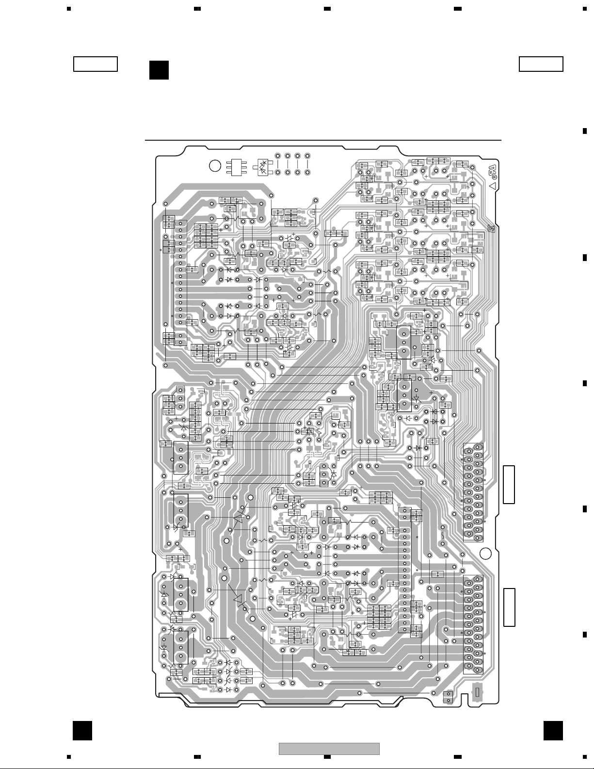
Page 34

1234
4.4 PRIMARY ASSY
SIDE A SIDE A
A
E
PRIMARY ASSY
B
4
C
H6H5
D
W163
To Power Transformer T1
CN1
3131
1
CN2
2
NE M PF2
CN1
W221
W220
FU3
W211
W210
W373
H3
W164
W372
YPW ONLY
Except YPW
W163,W164
Except DFL,YPW
W165
W166
W222,W223
1
C3
W214
W212
W213
W222
W223
DFL,YPW ONLY
W212,W213
W185
W186
W188
W187
W187,W188
DFL,YPW ONLY
SECONDARY
4
W215
Except DFL,YPW
W214,W215
L1
W347
Q51
C52
KN2
C51
RY51
Q51
1
T2
C2
W348
W368
W349
UNE+56
W369
5
9
W350
GNDS
W377
CN51
71
7
1
R1
CN51
1
D52
CN3053
D
FU2
H4
DFL ONLY
W133
W134
E
W331
W332
W101,W102
DFL ONLY
W114,W115
Except
DFL,YPW
Except YPW
W115
W114
S101 S102
PRIMARY
YPW ONLY
W371
W370
W101
W102
These knob position is
(S101 and S102)
240V
AN1
NEUTRAL
TUBE SIDE
C1
H2
FU1
H1
LIVE
(ANP7432-D)
F
E E
34
S-DV830
AN1
AC IN
1234
Page 35

5 678
SIDE B SIDE B
E
PRIMARY ASSY
CN51
CN51
Q52
D53
R54
Q52
71
R55
R52
-
D51
R53
R51
D54
+
D55
SECONDARY
CN1
G
4121
CN1CN2
NE M PF2
PRIMARY ASSY
A
B
C
LIVE
REPLACE WITH SAME TYPE
AND RATINGS OF FUSE
ATTENTION
REMPLACER PAR LE FUSIBLE PAR UN
MODELE INDENTIQUE EN INTENSITE
PRIMARY
110 - 120V 220 - 230V 240V
NEUTRAL
AWU8001
AWU8003
AWU8004
AWU8030
AWU8045
CAUTION
999
888
777
666
110 - 120V 220 - 230V 240V
D
1-A
8
7
AWU
555
444
333
222
111
000
E
(ANP7432-D)
AN1
E E
56
S-DV830
7
8
F
35
Page 36

1234
5. PCB PARTS LIST
A
NOTES:
Parts marked by "NSP" are generally unavailable because they are not in our Master Spare Parts List.
The mark found on some component parts indicates the importance of the safety factor of the part.
Therefore, when replacing, be sure to use parts of identical designation.
When ordering resistors, first convert resistance values into code form as shown in the following examples.
Ex.1 When there are 2 effective digits (any digit apart from 0), such as 560 ohm and 47k ohm (tolerance is shown by J=5%,
and K=10%).
560 Ω
47k Ω
0.5 Ω
1 Ω
56 x 10
47 x 10
R50
1R0
Ex.2 When there are 3 effective digits (such as in high precision metal film resistors).
5.62k Ω
B
Mark No. Description Part No.
LIST OF ASSEMBLIES
[S-DV830SW]
NSP 1..DVD AMP ASSY AWM7840
2..PRIMARY ASSY AWU8003
2..TRADE 1 ASSY AWU8028
2..POWER ASSY AWU8097
2..AF ASSY AWU8096
NSP 1..AMP MODULE 6CH AXQ7242
2..6CH AMP ASSY AWM7720
C
[S-DV99SW]
NSP 1..DVD AMP ASSY AWM7838
2..PRIMARY ASSY AWU8001
2..TRADE 1 ASSY AWU8028
2..POWER ASSY AWU8097
2..AF ASSY AWU8096
NSP 1..AMP MODULE 6CH AXQ7242
2..6CH AMP ASSY AWM7720
D
Mark No. Description Part No.
AF ASSY [AWU8096]
A
SEMICONDUCTORS
IC3002-IC3004, IC3102-IC3104 BA4558F-HT
IC3001 M62446AFP
IC3101 UPC4570G2
E
F
Q3004, Q3005 2SC4081
Q3009 UN5112
Q3081 UN511L
Q3008 UN5212
Q3006 UN521L
D3004-D3006 1SS133
D3003 MTZJ2.7B
D3001, D3002 UDZS6.8B
D3007-D3030 UDZS8.2B
CAPACITORS
C3034-C3036 CCSRCH101J50
C3130-C3134 CCSRCH471J50
C3003, C3004, C3009, C3010 CEAL100M16
C3015, C3016, C3019, C3020, C3043 CEAL100M16
36
1234
1
3
561
473
RD1/4PU J
RD1/4PU J
RN2H K
RS1P K
1
5621
RN1/4PC F562 x 10
561
473
R50
1R0
5621
Mark No. Description Part No.
C3045 CEAL100M16
C3032 CEAL101M6R3
C3021, C3022 CEAL221M10
C3048 CEAL470M16
C3037, C3121, C3122 CEAT100M50
C3081, C3082 CEAT220M50
C3038, C3047, C3107, C3108 CEAT470M25
C3118, C3119 CFTLA224J50
C3001, C3002, C3007, C3008 CKSRYB103K50
C3013, C3014, C3025, C3028, C3031 CKSRYB103K50
C3105, C3106, C3113, C3114, C3117 CKSRYB103K50
C3120 CKSRYB103K50
C3103, C3104, C3111, C3112, C3116 CKSRYB104K16
C3023, C3024 CKSRYB104K25
C3123 CKSRYB332K50
C9001, C9002 CKSRYB392K50
C3566, C3568 CKSRYB473K50
C3026, C3029 CKSRYB474K10
C3101, C3102, C3109, C3110, C3115 CKSRYB563K16
C3027, C3030 CKSRYB822K50
C3570 (10pF/100V) XCG3008
RESISTORS
R3035, R3036 RD1/2PM151J
R3041 RD1/2PM222J
R3040 RD1/4PU273J
R3050 RS1/10S0R0J
R3005-R3008, R3015-R3018 RS1/16S1001F
R3025-R3028 RS1/16S1001F
R3001-R3004, R3011-R3014 RS1/16S2201F
R3021-R3024 RS1/16S2201F
Other Resistors RS1/16S###J
OTHERS
3701 CABLE HOLDER(4P) 51052-0400
3702 CABLE HOLDER(10P) 51052-1000
CN3601 2P CONNECTOR 5569-02A1
CN3703-CN3705 23P SOCKET AKP7075
CN3702 20P SOCKET AKP7129
CN3701 AKP7131
CN3701 12P CONNECTOR AKP7131
J3701 JUMPER WIRE D25PYY0415E
J3702 JUMPER WIRE D25PYY1015E
PCB BINDER VEF1040
TRADE 1 ASSY [AWU8028]
B
OTHERS
S-DV830
Page 37

5 678
Mark No. Description Part No.
3703 CABLE HOLDER(4P) 51052-0400
3704 CABLE HOLDER(10P) 51052-1000
CN3707 13P SOCKET AKP7070
CN3706 15P SOCKET AKP7071
6CH AMP ASSY [AWM7720]
C
SEMICONDUCTORS
IC81 NJM7805FA
>
IC71 NJM7912FA
>
IC3301, IC3401 STK402-270
>
Q3382, Q43 2SA1576A
Q62 2SB1237X
Q111, Q3381, Q63, Q92 2SC4081
Q61 2SD2012
>
Q3301, Q3302, Q3401, Q3402 2SD2114K
Q3501, Q3502, Q3504 2SD2114K
Q3654 2SD2144S
Q107, Q3653 DTA124EUA
Q3652 DTA124TK
Q106 DTC124EUA
Q3383, Q91 IRFI9Z34G
>
Q3384 IRFIZ34G
>
Q3651 RN1901
Q101, Q103 UMB1N
Q102, Q104 UMH1N
D3321-D3326 1SR139-400
>
D3327, D3328 1SR139-400
D3421-D3426 1SR139-400
>
D3427, D3428 1SR139-400
D3387, D3388, D3651-D3655 1SS133
D101, D102, D104, D3657, D42 1SS355
D3391, D3392 30PDA20-FC6
D3381, D3382, D3481, D3482 DAN217
>
D3581, D3582 DAN217
>
D3389, D3390 MTZJ10C
D98 MTZJ11B
>
D72 MTZJ15C
>
D3393, D3394 MTZJ18B/C
D63 MTZJ18C
>
D3385, D3386 MTZJ36A
D82 MTZJ7.5C
>
D91 UDZS18B
D105, D106, D3658 UDZS7.5B
TH111 NCP18WF104J03RB
CAPACITORS
C3305, C3306, C3405, C3406 CCSRCH221J50
C3505, C3506, C62, C97 CCSRCH221J50
C3309, C3310, C3409, C3410 CCSRCJ3R0C50
C3509, C3510 CCSRCJ3R0C50
C3307, C3308, C3407, C3408, C3508 CEAL100M16
C3507 CEAL470M6R3
C72 CEAT100M50
C3651 CEAT101M25
C101, C102 CEAT1R0M50
C3323, C3324, C3423, C3424 CEAT221M50
C3167, C3168, C3178, C3179 CEAT2R2M50
C3301, C3302, C3317, C3318 CEAT2R2M50
C3401, C3402, C3501, C3502 CEAT2R2M50
C3652, C63, C82, C98 CEAT470M25
56
Mark No. Description Part No.
C3653 CEAT470M35
C3303, C3304, C3403, C3404 CKSRYB102K50
C3503, C3504 CKSRYB102K50
C92 CKSRYB104K16
C71, C81 CKSRYB473K50
RESISTORS
R3317-R3320, R3417-R3420 ACN7122
R3517-R3520 (0.22ohm/2W) ACN7122
R3327, R3328, R3427, R3428 RD1/4MUF470J
>
R3387, R3388 RD1/4PU101J
R3657 RD1/4PU330J
R96, R97 RS1/16S1002F
R3323, R3324, R3351, R3423, R3424 RS1/16S1R0J
>
R3451 RS1/16S1R0J
>
R67, R68 RS1/16S2201F
R94, R95 RS1/16S2701F
R62 RS1/16S330J
>
R65 RS1/16S4700F
R47, R48 RS1/16S4701F
Other Resistors RS1/16S###J
OTHERS
CN3001, CN3002 23P PLUG AKP7064
CN3651 PLUG(2P) KM200SA2
POWER ASSY [AWU8097]
D
SEMICONDUCTORS
IC3051 PROTECTOR(5A) AEK7046
>
IC33 NJM7812FA
>
Q3351, Q3352, Q3451, Q3452 2SC4081
Q3551, Q3552, Q3604, Q3605, Q3610 2SC4081
Q3612, Q3615 2SC4081
Q3614 2SD1858X
Q3606, Q3608 DTA123JS
Q3602 UN5112
Q3611, Q3613 UN511L
Q3603 UN5212
Q3601, Q3607, Q3609 UN521L
D3601-D3604, D3606 1SS133
D3351-D3354, D3361, D3451-D3454 1SS355
D3461, D3551-D3554, D3561 1SS355
D11, D31, D41 D5SBA20(B)
>
D3605 DA204K
COILS AND FILTERS
L3361, L3362, L3461, L3462 ATH-059
L3561, L3562 COIL ATH-059
CAPACITORS
C33, C34 (4700uF/35V) ACH7171
C3601 CEAL100M50
C3602 CEAL101M10
C3604 CEAL470M16
C35 CEAT100M50
C3603 CEAT101M10
C18, C19 CEAT222M50
C37 CEAT470M25
C42 CEAT682M25
C36 CKSRYB103K50
C3365-C3368, C3465-C3468, C3565 CKSRYB473K50
S-DV830
7
A
B
C
D
E
F
37
8
Page 38

1234
Mark No. Description Part No.
C3567 CKSRYB473K50
C31, C32 CQMBA103J50
A
C3605 (10uF/10V) DCH1148
C20–C23, C3301-C3304 XCG3008
C3369, C3370, C3469, C3470, C3569 XCG3008
(10pF/100V)
RESISTORS
R3351, R3352, R3451, R3452 ACN7112
R3551, R3552 (0.1ohm,2W) ACN7112
R3361, R3362, R3461, R3462 RD1/2PM101J
R3561, R3562 RD1/2PM101J
R31 RD1/4PU100J
B
R3602 RD1/4PU222J
R3621, R3622 RD1/4PU820J
Other Resistors RS1/16S###J
OTHERS
3401 SPEAKER TERMINAL10-P AKE7081
CN3053 7P PLUG AKP7056
CN3051 13P PLUG AKP7059
CN3054 15P PLUG AKP7060
CN3052 23P PLUG AKP7064
H41, H42 FUSE CLIP AKR7001
C
RY3361, RY3461, RY3561 SP RELAY ASR7008
CN11 CONNECTOR B7P-VH
KN3001 WRAPPING TERMINAL VNF1084
Mark No. Description Part No.
SEMICONDUCTORS
Q52 2SC4081
Q51 2SD1858X
D52 1SS133
D53, D54 1SS355
D51 S1WB(A)60SD
>
D55 UDZS20B
COILS AND FILTERS
L1 LINE FILTER ATF7018
>
TRANSFORMERS
T2 POWER TRANSFORMER ATT7078
>
CAPACITORS
C1, C2 (0.022F/AC275V) ACE7022
>
C3 (1000pF/AC250V) ACG7033
>
C52 CEAT102M25
RESISTORS
All Resistors RS1/16S###J
OTHERS
CN51 7P SOCKET AKP7067
H1, H2 FUSE CLIP AKR7001
RY51 RELAY ASR7027
>
CN1 CONNECTOR B2P3S-VH
>
AN1 AC INLET 1P XKP3041
>
PRIMARY ASSY [AWU8003]
E
SEMICONDUCTORS
Q52 2SC4081
Q51 2SD1858X
D52 1SS133
D53, D54 1SS355
D51 S1WB(A)60SD
>
D
D55 UDZS20B
COILS AND FILTERS
L1 LINE FILTER ATF7018
>
TRANSFORMERS
T2 POWER TRANSFORMER ATT7079
>
CAPACITORS
C1, C2 (0.022F/AC275V) ACE7022
>
C3 (1000pF/AC250V) ACG7033
>
C52 CEAT102M25
E
RESISTORS
R1 (2,2Mohm/ 1/2W) RCN1080
>
Other Resistors RS1/16S###J
OTHERS
CN51 7P SOCKET AKP7067
H1, H2 FUSE CLIP AKR7001
RY51 RELAY ASR7027
>
CN1 CONNECTOR B2P3S-VH
>
KN2 WRAPPING TERMINAL VNF1084
6. ADJUSTMENT
There is no information to be shown in this chapter.
AN1 AC INLET 1P XKP3042
>
F
PRIMARY ASSY [AWU8001]
E
38
1234
S-DV830
Page 39
5 678
7. GENERAL INFORMATION
7.1 DIAGNOSIS
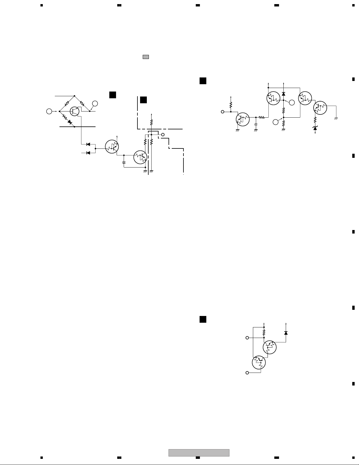
7.1.1 PROTECTION CIRCUIT
Note: Refer to the Schematic Diagram about the actual circuit.
(The & number corresponds to the marked circuits.)
1 Protection circuit when the Speaker terminal
becomes overloaded
POWER Assy
A
Front L ch
GND FL
Q3602
D
+5V
C3605
0.1
+
R3601
4.7k
Q3603
B
6CH AMP Assy
C
VD+5
R108
27k
R5527
270k
C
(DVD/CD TUNER)
CONTROL Assy
E
to
XPROTECT
B
R3353
R3355
33k
D3601
1.8k
R3351
0.1
Q3601
D3351
2 -1 Short-circuit-detection circuit for the amplifier
power circuit (VH+[VP+15], VD+5, -12 V [VA-12])
Circuit for shutting the power off when VP+15, VD+5, or VA-12
is short-circuited to ground (GND)
VH+
(VP+15)
Q101_1/2
(Q103_1/2)
R101
(R104)
1k
B
+
C101
(C102)
1/50
VD+5
E
C
Q101_2/2
(Q103_2/2)
E2
D101
(D102)
B
B
C2
R102
(R105)
10k
R103
A
(R106)
D105
10k
(D106)
B2
C2
E2
VH–
(VA–12)
Q102_2/2
(Q104_2/2)
B2
R109
820
6CH AMP Assy
C
VD+5
R108
Q102_1/2
(Q104_1/2)
27k
C
E
to
XPROTECT
(µ-com)
* ( )means the wiring No. of VP+15 line.
• In Normal mode, as Q101 (Q103) (E2, B2, C2) and Q102
(Q104) (E2, B2, C2) are on, the voltage at Point A is about 5 V.
The voltage at Point B is therefore about the same. As Q101
(Q103) (E, C, B) is off, Q102 (Q104) (E, C, B) is also off.
A
B
In Normal mode, the speaker (6 ohms) is connected between the
FL and GND FL points. Because the voltage at Point A is higher
than that at Point B, Q3601 does not operate.
If the resistance between the FL and GND FL points becomes
1.83 ohms or less, Q3601 begins to operate, Q3602 is turned on,
Q3603 (E, C, and B)is turned on, and the level of XPROTECT
becomes MID.
→ The microcomputer detects the XPROTECT level and
shuts the power to the unit off.
(1) When VH+(VP+15) is short-circuited to GND
As the voltage at Point B becomes almost ground potential, and
Q101 (Q103) (E, C, B) then Q102 (Q104) (E, C, B) are turned on,
the level of XPROTECT becomes low.
→ The microcomputer detects the XPROTECT level and shuts
the power to the unit off.
(2) When VH-(VA-12) is short-circuited
As the electric potential of VE at Q102 (Q104) (E2, C2, B2)
becomes the same as that at VB, Q102 (Q104) (E2, C2, B2) is
turned off. Following this, Q101 (Q103) (E2, B2, C2) is turned
off, which changes the voltage at Points A and B to a value other
than 5 V. Therefore, Q101 (Q103) (E, C, B) then Q102 (Q104) (E,
C, B) are turned on, the level of XPROTECT becomes low.
(3) When VD+5 is short-circuited
The level of the XPROTECT line becomes low. The
microcomputer detects the XPROTECT level and shuts the power
to the unit off.
2 -2 Short-circuit-detection circuit for the DVD power
Line (VP+8)
6CH AMP Assy
C
XPROTECT
TUNER
VD+5
R108
27k
DTA124EUA
VP+8
Q106
DTC124EUA
Q107
D104
1SS355
As the TUNER line is fixed to GND level, Q107 is always on. If
the level at VP+8 falls to GND level because of short-circuit, etc.,
Q106 is turned on, and the level of the XPROTECT line becomes
low.
← The microcomputer detects the XPROTECT level and shuts
the power to the unit off.
C
D
E
56
S-DV830
F
7
8
39
Page 40

1234
3 FAN detection circuit
6CH AMP Assy
C
A
to
XPROTECT
(µ-com)
B
If no fan is connected between FAN+ and FAN-, or when the fan
cannot rotate because of a foreign object caught in the blades,
current will not flow to R3657, and Q3652 and Q3651B) are turned off. Then Q3651the level of XPROTECT becomes low.
→ The microcomputer detects the XPROTECT level and shuts
When FAN+ and FAN- are short-circuited, the electric potential at
C
Point A becomes higher than GND level by the addition of the
values at D3656 and D3657. As this value is lower than that at
D3658, Q3651 (E, C, B) is turned off, Q3651 (E2, B2, C2) is
turned on, and the level of XPROTECT becomes low.
VD+5
Q3651_2/2
RN1901
R108
27k
C2
E2
C
B2
E
Q3651_1/2
RN1901
R3654
1.8k
the power to the unit off.
VPF+15
D3658
A
8.2k
R3658
2.2k
D3657
1SS355
2SD2144S
Q3652
DTA124TK
Q3654
R3656
22k
V-12F
UDZS7.5B
B
+
C3652
47/50
R3655
2/2 (E2, B2, C2) is turned on, and
R3657
33(1/4W)
D3655
1SS133
1/2 (E, C,
FAN+
FAN –
D3651-D3654
1SS133×4
5 IC81 abnormal temperature detection circuit
IC81
NJM7805FA
R111
1k
VD+5
NCP18WF104J03RB
R113
A
220
R112
1k
TH111
C
Q111
2SC4081
6CH AMP
Assy
to
XPROTECT
The voltage at Point A becomes the divided voltage of TH111
and R111//R112 (combined resistance of parallel-connected
resistors R111 and R112.) In Normal mode, the resistance at
TH111 is much higher than R111//R112, and Q111 is off. (Note
that the resistance at TH111 becomes lower as the temperature
increases.) If the solder temperature at IC81 increases abnormally,
the temperature at TH111 (thermistor) mounted closest to the land
of IC81 increases accordingly, and the resistance at TH111
decreases.
When the temperature at TH111 reaches 90-110_C (varying
according to conditions,) the voltage at Point (A) becomes high
enough to turn Q111 on, and the level of the XPROTECT line
becomes low. The microcomputer detects the XPROTECT level
and shuts the power to the unit off.
4
DC detection circuit of SP terminal
POWER Assy
D
R3357
(C, SR)
(R3457)
18k
R3358
(R3458)
18k
R3603
10k
+
C3602
100/10
Q3605
D
Front L ch
(SW, SL)
Front R ch
Q3606
B
Q3604
+5V
E
C
Q3607
• In Normal mode, both Q3605 and Q3604 are off.
(1) When positive (+) DC voltage is generated at the SP
terminal
When positive (+) DC voltage is generated at the L or R channel,
E
and VB of Q3605 becomes higher than that at the operation point,
Q3606 (E, C, B) is turned on, and the level of XPROTECT
becomes low.
→ The microcomputer detects the XPROTECT level and shuts
the power to the unit off.
(2) When negative (-) DC voltage was generated at the SP
terminal
Q3604 is turned on, and XPROTECT is activated.
C
VD+5
6CH AMP
Assy
R108
27k
XPROTECT
F
40
S-DV830
1234
Page 41
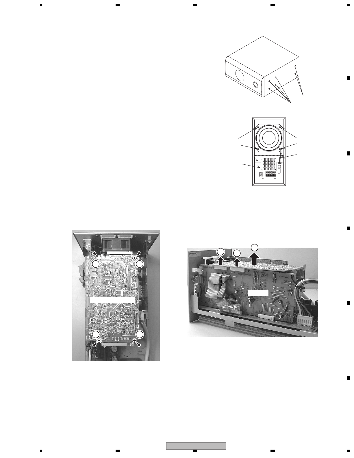
5 678
7.1.2 DISASSEMBLY
1. Removing the Amplifier Assy
1) The Amplifier Assy is attached to the cabinet by six external
screws 1. To detach it, pull down the subwoofer toward the
left side.
2) Then unfasten those screws 1 .
3) Then stand up the speaker again. To detach the Amplifier Assy,
first remove the connecting code. Then pull straight the Amplifier
Assy toward back and remove it.
2. Removing the Subwoofer
1) The speaker element is attached to the back board by four external
screws 2. To detach it, unfasten those screws.
2) When attaching it,face its terminal upward.
3. Removing the Cosmetic Baffle
1) The cosmetic baffie is attached to the baffle by press-fitting.
To detach it,pry it open by inserting a flat blade screwdriver
into lower side.
4. Removing the Cosmetic Duct
1) The cosmetic baffle, those screws are removed when removing the
cosmetic duct attached in cosmetic baffle with four screws.
5. Diagnosis
1) Remove the four screws 3.
2) Disconnect the two connectors 4.
3) Remove the AMP MODULE 5.
Screw 2
Amplifier Assy
A
Screw 1
Screw 1
B
Screw 2
Connecting Code
C
3 3
AMP MODULE 6CH
3 3
4
4
5
D
AF Assy
E
F
56
S-DV830
7
8
41
Page 42
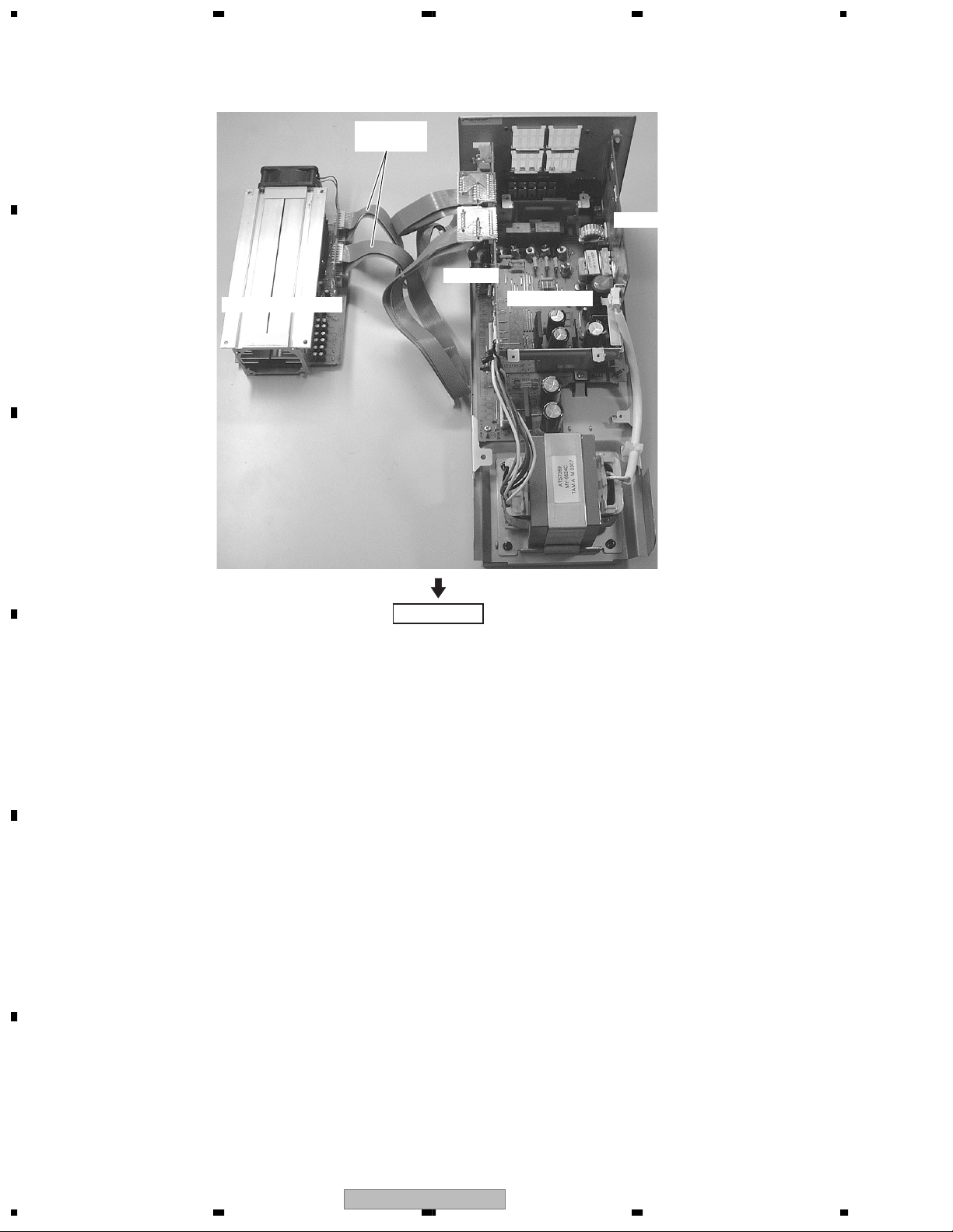
1234
4) Connect the two jig cables as figure below.
A
B
AMP MODULE 6CH
Jig Cable
(GGD1315)
PRIMARY Assy
AF Assy
POWER Assy
C
Diagnosis
D
E
F
42
1234
S-DV830
Page 43
5 678
7.2 IC
• The information shown in the list is basic information and may not correspond exactly to that shown in the schematic diagrams.
M62446AFP (AF ASSY : IC3001)
EXPAND port in E-vol IC
No. Mark Pin Name Pin Function Active
3Q2CMUTE
2Q3SPRYRC
1Q4SPRYS
Control C mute
Control relay for rear and center speaker
Control relay for front speaker
H
H
H
A
7.3 CLEANING
Before shipping out the product, be sure to clean the following positions by using the prescribed cleaning tools:
Position to be cleaned Cleaning tools
Fans Cleaning paper : GED-008
B
C
D
56
S-DV830
E
F
7
8
43
 Loading...