

Page 1
PIONEER CORPORATION 4-1, Meguro 1-chome, Meguro-ku, Tokyo 153-8654, Japan
PIONEER ELECTRONICS (USA) INC. P. O. Box 1760, Long Beach, CA 90801-1760, U.S.A.
PIONEER EUROPE NV Haven 1087, Keetberglaan 1, 9120 Melsele, Belgium
PIONEER ELECTRONICS ASIACENTRE PTE. LTD. 253 Alexandra Road, #04-01, Singapore 159936
PIONEER CORPORATION 2008
Center
Front
Surround
S-DV390T
This service manual is intended for qualified service technicians; it is not meant for the casual
do-it-yourselfer. Qualified technicians have the necessary test equipment and tools, and have been
trained to properly and safely repair complex products such as those covered by this manual.
Improperly performed repairs can adversely affect the safety and reliability of the product and may
void the warranty. If you are not qualified to perform the repair of this product properly and safely,
you should not risk trying to do so and refer the repair to a qualified service technician.
WARNING
This product contains certain electrical parts contain chemicals which are known to the State of California to cause cancer,
birth defects or other reproductive harm.
Health & Safety Code Section 25249.6 - Proposition 65
SPEAKER SYSTEM
S-DV390T
ORDER NO.
RRV3799
/SXTW/WL5
T-ZZR JULY 2008 Printerd in Japan
Page 2
1
Speaker Stand Base
Stem
(the bottom of cabinet)
Front
Rear
2 3
1. REASSEMBLY AND DISASSEMBLY PRECAUTIONS
1.1 FRONT SPEAKER
A
GRILLE
The grille is attached to the cabinet by its bosses applied with
ad hesive. To detach it, pry it op en by inser t ing a flat blad e
screwdriver into lower right and lower left slot. To attach it, apply
adhesive to the holes on the baffle. Then press it to the baffle.
CAUTION
There are 12 bosses for press-fitting at the grille. To detach the
grille, remove in order from lower bosses. (Refer to the figure
in page 4.) In order not to damage the bosses, don't remove it
forcibly. Pry it open little by little. Be sure to insert a flat blade
B
screwdriver from just beside of its bosses.
WOOFER
The woofer is attached to the baff le by 4 external screws. To
detach it, unfasten those screws. To detach it, first remove the
gr i lle. Then remove the scr ews. When att ach ing it, face it s
terminal downward.
TWEETER
The tweeter is attached to the baffle by 3 external screws. To
detach it, unfasten those screws. To detach it, first remove the
C
gr i lle. Then remove the scr ews. When att ach ing it, face it s
terminal leftward and rightward.
COSMETIC PANEL
The cosmetic panel is attached to the baff le by its bosses. To
detach it, pry it open by inserting a f lat blade screwdriver into
lower slot. To detach it, first remove the speaker stand base and
grille. Then remove the cosmetic panel. When attaching it, fit the
boss into the hole on the baffle.
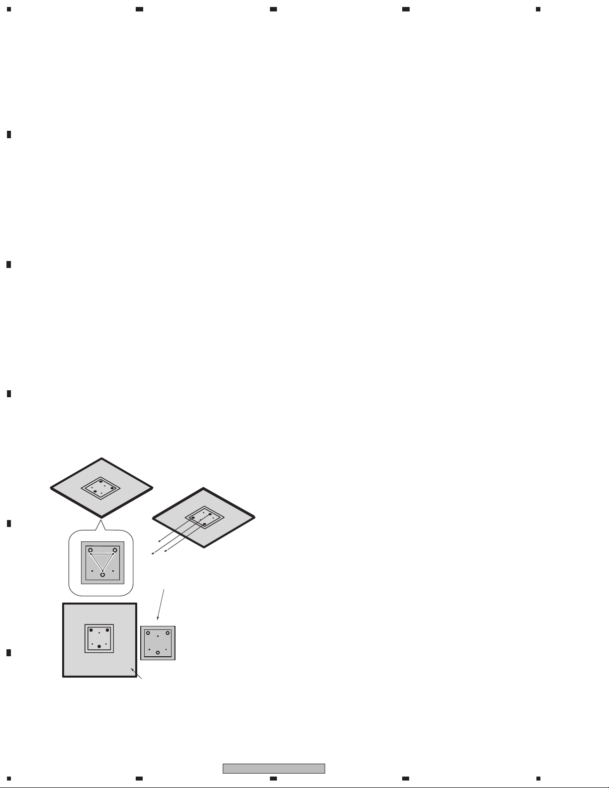
SPEAKER STAND BASES
The speaker stand base is attached to the bottom of cabinet by 3
external screws. To detach it, unfasten those screws. Attach the
speaker stand bases to the stems using the screws provided. Once
you have aligned the stem and base, secure with the small screws
at the points shown below. Note that the speaker should face in
the direction of the base of the isosceles triangle (outlined below).
1.2 CENTER SPEAKER
GRILLE
The gr ille is attached to the cabinet by 8 exter nal screws. To
detach it, unfasten those screws.
SPEAKER UNIT
The speaker u nit, toget her with the grille, is atta ched to the
cabinet by 4 external screws. To detach it, first unfasten those
screws. Next remove the cabinet. Then remove the cable. When
re-attaching it, face its terminal toward the leftward.
1.3 SURROUND SPEAKER
GRILLE
The gr ille is attached to the cabinet by 4 exter nal screws. To
detach it, unfasten those screws.
SPEAKER UNIT
The speaker u nit, toget her with the grille, is atta ched to the
cabinet by 4 external screws. To detach it, first unfasten those
screws. Next remove the cabinet. Then remove the cable. When
re-attaching it, face its terminal downward.
4
D
E
F
2
1 2 3 4
S-DV390T
Page 3
5
Parts marked by "NSP" are generally unavailable because they are not in our Master Spare Parts List.
The mark found on some component parts indicates the importance of the safety factor of the part.
Therefore, when replacing, be sure to use parts of identical designation.
NOTES:
6 7
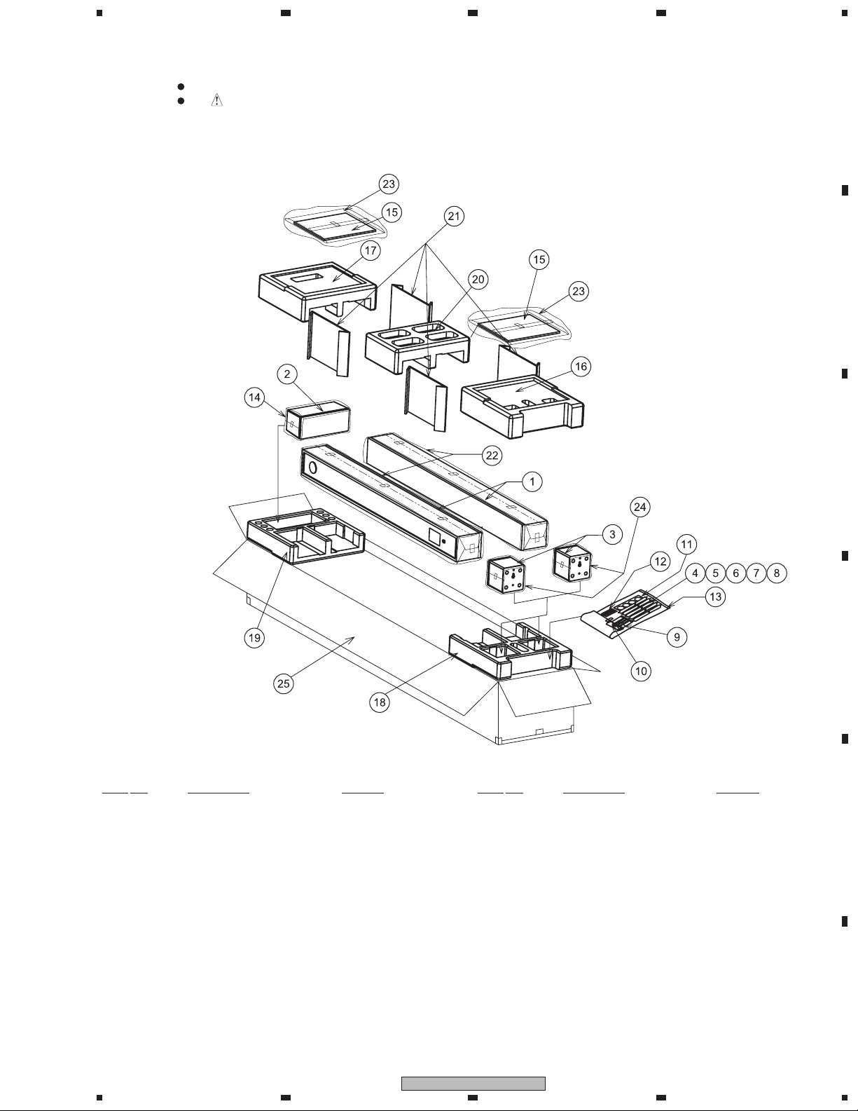
2. EXPLODED VIEWS AND PARTS LIST
2.1 PACKING
8
A
B
PACKING Parts List
Mark No. Description Part No. Mark No. Description Part No.
NSP 1 CS Assy (Front) SMW6274
NSP 2 CS Assy (Center) SMW6275
NSP 3 CS Assy (Surround) SMW6279
4 Speaker Cord (FL: White) SDS1174
5 Speaker Cord (FR: Red) SDS1175
6 Speaker Cord (SL: Blue) SDS1176
7 Speaker Cord (SR: Gray) SDS1177
8 Speaker Cord (C: Green) SDS1178
9 Screw (for Speaker Stand Base) CYC40P300FTC
10 Polyethylene Bag S0 (for Screw) SHL1314
11 Non Skid Pad SEP6015
(for Speaker Stand Base)
12 Non Skid Pad (for Surround) SEP6027
13 Polyethylene Bag SHL1251
(for Accessory Set)
14 Polyethylene BagS2 SHL1417
(for Center Sp)
5
6
15 Speaker Stand Base SMS6033
16 Protector (Top) SHA6166
17 Protector (Top) SHA6167
18 Protector (Bottom) SHA6168
19 Protector (Bottom) SHA6169
20 Protector (Top) SHA6170
21 Spacer SHB6057
22 Protection Sheet SHC6051
23 Protection Sheet SHC6082
(for Speaker Stand Base)
24 Polyethylene Bag S2 SHL1420
(for Surround Sp)
25 Packing Case SHG6365
S-DV390T
7
C
D
E
F
3
8
Page 4

1
Speaker Stand Base
(refer to 2.1 PACKING / No.15)
Screw (x3)
(refer to 2.1 PACKING / No.9)
Model Label
Red
White
Red
Black
: the attached to
the applied with
adhesive.
2.2 CS Assy (FRONT)
A
B
2 3
4
C
D
E
CS Assy (FRONT) Parts List
Mark No. Description Part No. Mark No. Description Part No.
1 Grille SMG6141
2 Cosmetic Plate Assy SNK6222
3 Input Terminal SKX1060
4 Fastener SNB6003
5 Network Assy SWN6028
F
4
1 2 3 4
S-DV390T
6 Speaker (for Woofer) K77DR55-56C
7 Speaker (for Tweeter) FK26AP32-51G
8 Screw (for Tweeter) BYC35P160FTC
9 Screw (for Woofer) BYC35P120FTC
10 Screw (for Fastener) BYC35P120FTB
11 Badge Plate SNK6221
Page 5

5
Cabinet
5
8
2
Model Label
10
(x8)
4
9
11
12
2.3 CS Assy (CENTER)
6 7
8
A
B
C
D
CS Assy (CENTER) Parts List
Mark No. Description Part No.
1 Grille SMG6129
2 Connecting Cord SDD1345
3 Input Terminal SKX6034
4 Speaker K77DR55-55C
5 Screw (for Input Terminal) BPZ35P080FTC
E
6 Screw (for Cabinet) BPZ35P110FTB
7 Non Skid Pads SEP1263
8 Non Skid Pad SEP6028
5
F
S-DV390T
6
7
8
5
Page 6

1
Model Label
Caution
Packing
Cabinet
2.4 CS Assy (SURROUND)
A
B
2 3
4
C
D
CS Assy (SURROUND) Parts List
Mark No. Description Part No.
1 Grille SMG6128
2 Connecting Cord SDD1345
3 Input Terminal SKX6034
4 Speaker K77DR55-55C
5 Screw (for Input Terminal) BPZ35P080FTC
E
6 Screw (for Cabinet) BPZ35P110FTB
F
6
1 2 3 4
S-DV390T
Page 7

5
Network Assy (SWN6028)
INPUT
Woofer
Black
Red
Black
Red
Tweeter
1.0 uF / 63 V
Long Leg
C
White
Red
Short Leg
INPUT Speaker
White
Red
Connecting Cord (SDD1345)
6 7
3. SCHEMATIC DIAGRAM
3.1 NETWORK ASSY (FRONT)
8
A
B
3.2 NETWORK ASSY (CENTER, SURROUND)
C
D
E
S-DV390T
5
6
F
7
7
8
 Loading...