

Pioneer PRSD-1200-SPL Service manual

This file was downloaded and provided FREE OF CHARGE
from the ManualDirectory community.
You can find many free to download Service Manuals & Schematics at
http://www.manualdirectory.co.uk
CLASS D MONO AMPLIFIER
ORDER NO.
CRT3933
PRS-D1200SPL/XU/UC
PRS-D1200SPL
PRS-D1200SPL
/XUEW5
/XU/UC
For details, refer to "Important check points for good servicing".
PIONEER CORPORATION 4-1, Meguro 1-chome, Meguro-ku, Tokyo 153-8654, Japan
PIONEER ELECTRONICS (USA) INC. P.O. Box 1760, Long Beach, CA 90801-1760, U.S.A.
PIONEER EUROPE NV Haven 1087, Keetberglaan 1, 9120 Melsele, Belgium
PIONEER ELECTRONICS ASIACENTRE PTE. LTD. 253 Alexandra Road, #04-01, Singapore 159936
PIONEER CORPORATION 2007
K-ZZA. MAY 2007 Printed in Japan

1234
SAFETY INFORMATION
CAUTION
A
This service manual is intended for qualified service technicians; it is not meant for the casual do-it-yourselfer.
Qualified technicians have the necessary test equipment and tools, and have been trained to properly and safely repair
complex products such as those covered by this manual.
Improperly performed repairs can adversely affect the safety and reliability of the product and may void the warranty. If you
are not qualified to perform the repair of this product properly and safely, you should not risk trying to do so and refer the
repair to a qualified service technician.
WARNING
This product contains lead in solder and certain electrical parts contain chemicals which are known to the state of California
B
to cause cancer, birth defects or other reproductive harm.
Health & Safety Code Section 25249.6 - Proposition 65
C
D
E
F
2
1234
PRS-D1200SPL/XU/UC
5 678
[Important Check Points for Good Servicing]
In this manual, procedures that must be performed during repairs are marked with the below symbol.
Please be sure to confirm and follow these procedures.
1. Product safety
Please conform to product regulations (such as safety and radiation regulations), and maintain a safe servicing environment by
following the safety instructions described in this manual.
1 Use specified parts for repair.
Use genuine parts. Be sure to use important parts for safety.
2 Do not perform modifications without proper instructions.
Please follow the specified safety methods when modification(addition/change of parts) is required due to interferences such as
radio/TV interference and foreign noise.
3 Make sure the soldering of repaired locations is properly performed.
When you solder while repairing, please be sure that there are no cold solder and other debris.
Soldering should be finished with the proper quantity. (Refer to the example)
4 Make sure the screws are tightly fastened.
Please be sure that all screws are fastened, and that there are no loose screws.
5 Make sure each connectors are correctly inserted.
Please be sure that all connectors are inserted, and that there are no imperfect insertion.
6 Make sure the wiring cables are set to their original state.
Please replace the wiring and cables to the original state after repairs.
In addition, be sure that there are no pinched wires, etc.
7 Make sure screws and soldering scraps do not remain inside the product.
Please check that neither solder debris nor screws remain inside the product.
8 There should be no semi-broken wires, scratches, melting, etc. on the coating of the power cord.
Damaged power cords may lead to fire accidents, so please be sure that there are no damages.
If you find a damaged power cord, please exchange it with a suitable one.
9 There should be no spark traces or similar marks on the power plug.
When spark traces or similar marks are found on the power supply plug, please check the connection and advise on secure
connections and suitable usage. Please exchange the power cord if necessary.
a Safe environment should be secured during servicing.
When you perform repairs, please pay attention to static electricity, furniture, household articles, etc. in order to prevent injuries.
Please pay attention to your surroundings and repair safely.
A
B
C
D
2. Adjustments
To keep the original performance of the products, optimum adjustments and confirmation of characteristics within specification.
Adjustments should be performed in accordance with the procedures/instructions described in this manual.
3. Lubricants, Glues, and Replacement parts
Use grease and adhesives that are equal to the specified substance.
Make sure the proper amount is applied.
4. Cleaning
For parts that require cleaning, such as optical pickups, tape deck heads, lenses and mirrors used in projection monitors, proper
cleaning should be performed to restore their performances.
5. Shipping mode and Shipping screws
To protect products from damages or failures during transit, the shipping mode should be set or the shipping screws should be
installed before shipment. Please be sure to follow this method especially if it is specified in this manual.
56
PRS-D1200SPL/XU/UC
E
F
7
8
3

1234
CONTENTS
SAFETY INFORMATION..................................................................................................................................... 2
1. SERVICE PRECAUTIONS............................................................................................................................... 5
A
B
C
1.1 SERVICE PRECAUTIONS ........................................................................................................................ 5
1.2 NOTES ON SOLDERING .......................................................................................................................... 5
2. SPECIFICATIONS............................................................................................................................................ 6
2.1 SPECIFICATIONS ..................................................................................................................................... 6
2.2 PANEL FACILITIES.................................................................................................................................... 7
2.3 CONNECTION DIAGRAM ......................................................................................................................... 8
3. BASIC ITEMS FOR SERVICE.......................................................................................................................... 9
3.1 CHECK POINTS AFTER SERVICING....................................................................................................... 9
3.2 JIGS LIST ................................................................................................................................................ 10
4. BLOCK DIAGRAM...........................................................................................................................................11
5. DIAGNOSIS.................................................................................................................................................... 12
5.1 CONNECTOR FUNCTION DESCRIPTION............................................................................................. 12
6. SERVICE MODE ............................................................................................................................................ 13
7. DISASSEMBLY .............................................................................................................................................. 14
8. EACH SETTING AND ADJUSTMENT ........................................................................................................... 18
8.1 ADJUSTMENT......................................................................................................................................... 18
9. EXPLODED VIEWS AND PARTS LIST.......................................................................................................... 20
9.1 PACKING ................................................................................................................................................. 20
9.2 EXTERIOR............................................................................................................................................... 22
10. SCHEMATIC DIAGRAM............................................................................................................................... 26
10.1 SCHEMATIC DIAGRAM(GUIDE PAGE)................................................................................................ 26
10.2 REMOTE CONTROL UNIT.................................................................................................................... 32
11. PCB CONNECTION DIAGRAM.................................................................................................................... 34
11.1 AMP UNIT .............................................................................................................................................. 34
11.2 REMOTE CONTROL UNIT .................................................................................................................... 38
12. ELECTRICAL PARTS LIST .......................................................................................................................... 39
D
E
F
4
1234
PRS-D1200SPL/XU/UC

5 678
1. SERVICE PRECAUTIONS
1.1 SERVICE PRECAUTIONS
- Service Precaution
1. You should conform to the regulations governing the product (safety, radio and noise, and other regulations),
and should keep the safety during servicing by following the safety instructions described in this manual.
2. Be careful in handling ICs. Some ICs such as MOS type are so fragile that they can be damaged by
electrostatic induction.
3. The area where the temperature gets high as a completely assembled product is the heat sink. As a unit, on
the other hand, sub-heat sink and the periphery of the sub-heat sink are the areas where the temperature
gets high.
4. There is a danger for electrical shock in the periphery of an area where “CAUTION High Voltage” is indicated
on the printed circuit board due to a high voltage being generated during operation. Therefore, be careful
when working around such areas.
5. The Holder Unit(CXC8183) cannot be used again when removing once. Please exchange it for new parts when you
remove the Holder Unit from the product. Reattachment of the Holder Unit having once peeled off may possibly leak
the light from an aperture generated by the weak adhesion of two-sided tape.
6. Since the secondary voltage is not discharged upon power-off of the product after the product operation check (some
residual voltage is left even after five minutes), forcibly discharge the voltage or conduct servicing after checking the
voltage with a tester.
7. When replacing the power FET or the output FET, parts connected in parallel need to be replaced at the same time.
A
B
1.2 NOTES ON SOLDERING
NOTES ON SOLDERING
For environmental protection, lead-free solder is used on the printed circuit boards mounted in this unit.
Be sure to use lead-free solder and a soldering iron that can meet specifications for use with lead-free solders for repairs
accompanied by reworking of soldering.
Compared with conventional eutectic solders, lead-free solders have higher melting points, by approximately 40 C.
Therefore, for lead-free soldering, the tip temperature of a soldering iron must be set to around 373 C in general, although
the temperature depends on the heat capacity of the PC board on which reworking is required and the weight of the tip of
the soldering iron.
Compared with eutectic solders, lead-free solders have higher bond strengths but slower wetting times and higher melting
temperatures (hard to melt/easy to harden).
The following lead-free solders are available as service parts:
Parts numbers of lead-free solder:
GYP1006 1.0 in dia.
GYP1007 0.6 in dia.
GYP1008 0.3 in dia.
C
D
E
56
PRS-D1200SPL/XU/UC
F
7
8
5

1234
2. SPECIFICATIONS
2.1 SPECIFICATIONS
A
B
C
D
E
F
6
1234
PRS-D1200SPL/XU/UC

5 678
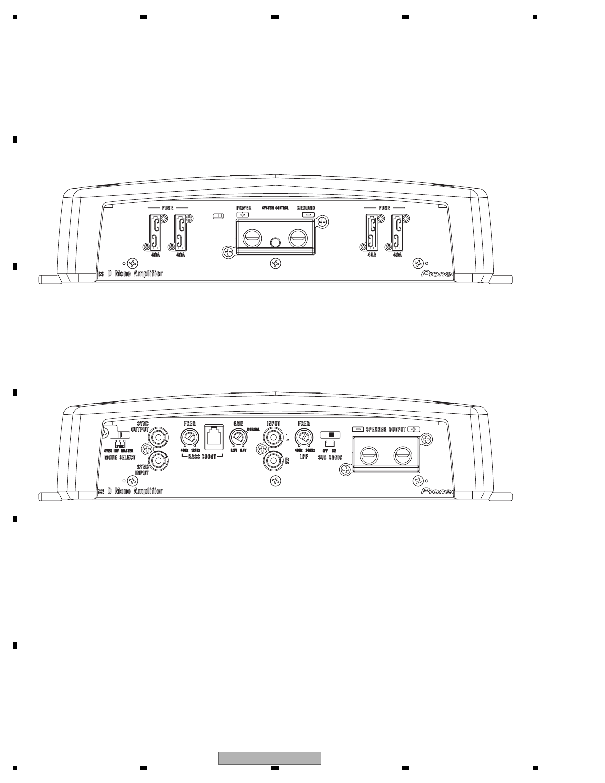
2.2 PANEL FACILITIES
A
B
C
D
E
56
PRS-D1200SPL/XU/UC
F
7
8
7

1234
2.3 CONNECTION DIAGRAM
A
B
C
D
E
F
8
1234
PRS-D1200SPL/XU/UC
5 678
3. BASIC ITEMS FOR SERVICE
3.1 CHECK POINTS AFTER SERVICING
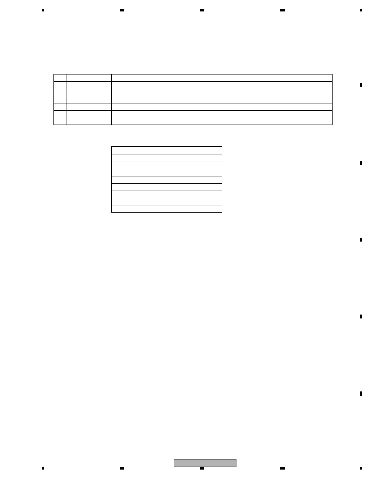
To keep the product quality after servicing, please confirm following check points.
No. Procedures Item to be confirmed
1 Confirm whether the customer complain has
been solved.
2 Check the output sound. Audio and operations must be normal.
3 Appearance check No scratches or dirt on its appearance after
See the table below for the items to be checked regarding video and audio:
Item to be checked regarding audio
Distortion
Noise
Volume too low
Volume too high
Volume fluctuating
Sound interrupted
The customer complain must not be
reappeared.
Audio and operations must be normal.
receiving it for service.
A
B
C
D
E
F
56
PRS-D1200SPL/XU/UC
7
8
9

1234
3.2 JIGS LIST
- Lubricants and Glues list
A
Name
Bond
Bond
(*) You can use GEM1017 even if the color is defferent from the original ones.
B
Jig No.
GEM1017
GYL1006
Remarks
Applying to Chemical Capacitor etc. (*)
Applying to Thermistor
C
D
E
F
10
1234
PRS-D1200SPL/XU/UC

5 678
4. BLOCK DIAGRAM
There is no information to be shown in this chapter.
A
B
C
D
E
56
PRS-D1200SPL/XU/UC
F
7
8
11
1234
5. DIAGNOSIS
5.1 CONNECTOR FUNCTION DESCRIPTION
A
B
C
D
E
F
12
1234
PRS-D1200SPL/XU/UC

5 678
6. SERVICE MODE
There is no information to be shown in this chapter.
A
B
C
D
E
56
PRS-D1200SPL/XU/UC
F
7
8
13
 Loading...