

ORDER NO.
PDP-S40U
RRV3398
SPEAKER SYSTEM
PDP-S40U XTW/UC
This service manual is intended for qualified service technicians; it is not meant for the casual do-ityourselfer. Qualified technicians have the necessary test equipment and tools, and have been trained to
properly and safely repair complex products such as those covered by this manual.
Improperly performed repairs can adversely affect the safety and reliability of the product and may void the
warranty. If you are not qualified to perform the repair of this product properly and safely, you should not risk
trying to do so and refer the repair to a qualified service technician.
WARNING
This product contains lead in solder and certain electrical parts contain chemicals which are known to the state of California to
cause cancer, birth defects or other reproductive harm.
Health & Safety Code Section 25249.6 – Proposition 65
PIONEER CORPORATION 4-1, Meguro 1-chome, Meguro-ku, Tokyo 153-8654, Japan
PIONEER ELECTRONICS (USA) INC. P.O. Box 1760, Long Beach, CA 90801-1760, U.S.A.
PIONEER EUROPE NV Haven 1087, Keetberglaan 1, 9120 Melsele, Belgium
PIONEER ELECTRONICS ASIACENTRE PTE. LTD. 253 Alexandra Road, #04-01, Singapore 159936
PIONEER CORPORATION 2006
T – ZZM MAY 2006 Printed in Japan
1
23
4
1.REASSEMBLY AND DISASSEMBLY PRECAUTIONS
A
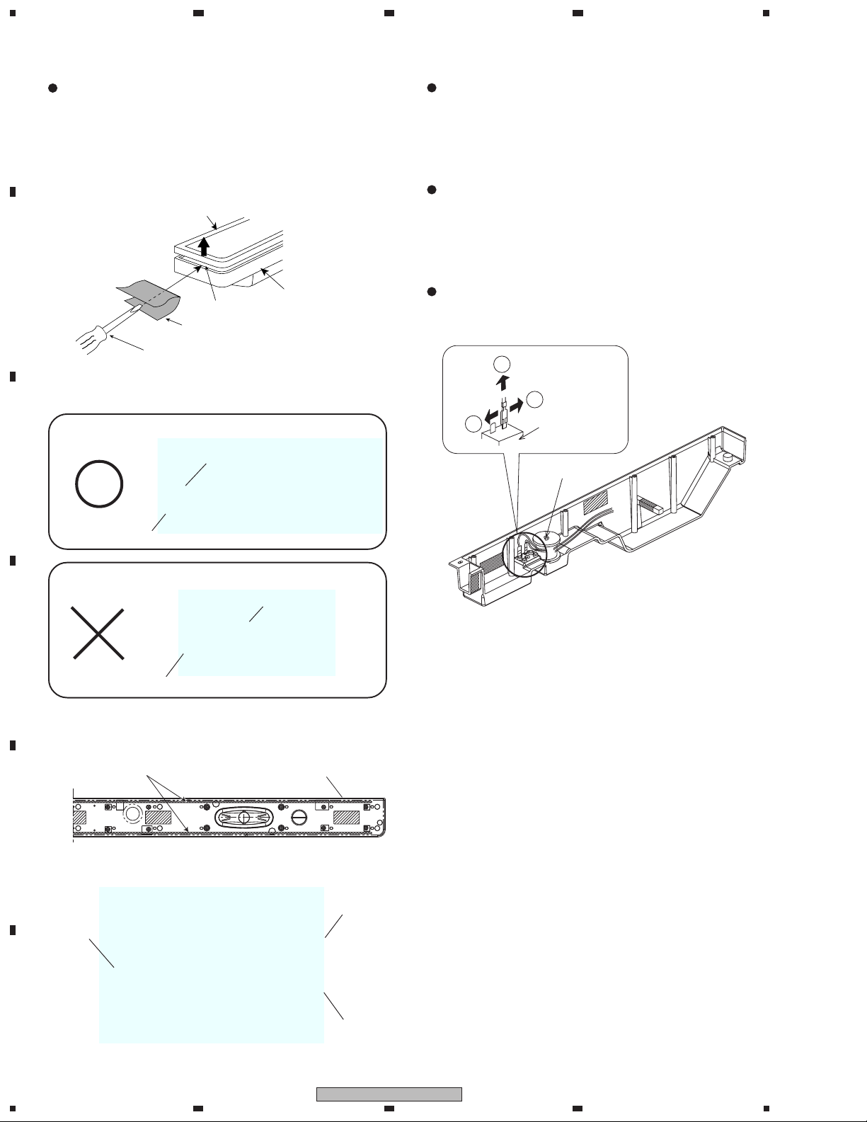
The grille ASSY is attached to the baffle by its bosses and
double-sided self-adhesive tape.
To detach it, first remove the packing on the top of the unit.
Then pry it open little by little by inserting a flat blade screwdriver (covered with a cloth) into the slot between the grille
ASSY and the baffle.
Grille ASSY
B
Slot
Baffle
Cloth
Screwdriver(-)
*Be careful not to damage the grille ASSY by bending too much.
Grille ASSY
C
The woofer is attached to the baffle by 4 internal screws.
To detach it, unfasten the 6 screws on the back of cabinet C.
Then, unfasten the 12 screws on the front of cabinet L. Do the
same for cabinet R.
When attaching, the plus terminal should be facing inward.
The tweeter is attached to the baffle by 2 internal screws.
To detach it, unfasten the 6 screws on the back of cabinet C.
Then, unfasten the 12 screws on the front of cabinet L. Do the
same for cabinet R.
When attaching, the plus terminal should be facing upward.
It is hard-wired between the input terminal and the network
ASSY. When detaching the Network ASSY, swing to pull it
out.
2
1
1
Input terminal
Network ASSY
Baffle
Grille ASSY
D
Baffle
To re-attach it, press it to the baffle using new double-sided
self-adhesive tape.
Tape
SEH1089
E
Baffle
Then, attach new packing on the top of the unit.
Baffle
Packing
F
Grille ASSY
2
1234
PDP-S40U
 Loading...